EP3023943A1 - Steuerung, steuerungsverfahren und computerlesbares aufzeichnungsmedium - Google Patents
Steuerung, steuerungsverfahren und computerlesbares aufzeichnungsmedium Download PDFInfo
- Publication number
- EP3023943A1 EP3023943A1 EP15195210.8A EP15195210A EP3023943A1 EP 3023943 A1 EP3023943 A1 EP 3023943A1 EP 15195210 A EP15195210 A EP 15195210A EP 3023943 A1 EP3023943 A1 EP 3023943A1
- Authority
- EP
- European Patent Office
- Prior art keywords
- opening
- unit
- motion
- closing
- reception
- Prior art date
- Legal status (The legal status is an assumption and is not a legal conclusion. Google has not performed a legal analysis and makes no representation as to the accuracy of the status listed.)
- Granted
Links
- 238000000034 method Methods 0.000 title claims description 17
- 230000033001 locomotion Effects 0.000 claims abstract description 127
- 238000003384 imaging method Methods 0.000 claims abstract description 64
- 230000008859 change Effects 0.000 claims abstract description 60
- 238000001514 detection method Methods 0.000 claims abstract description 34
- 230000002093 peripheral effect Effects 0.000 claims abstract description 30
- 238000004891 communication Methods 0.000 claims description 24
- 230000001939 inductive effect Effects 0.000 claims description 2
- 238000012545 processing Methods 0.000 description 18
- 230000007257 malfunction Effects 0.000 description 5
- 238000010586 diagram Methods 0.000 description 4
- 230000006870 function Effects 0.000 description 4
- 238000013459 approach Methods 0.000 description 3
- 239000003550 marker Substances 0.000 description 3
- 238000004458 analytical method Methods 0.000 description 2
- 230000000694 effects Effects 0.000 description 2
- 238000005259 measurement Methods 0.000 description 2
- 230000005540 biological transmission Effects 0.000 description 1
- 230000000903 blocking effect Effects 0.000 description 1
- 238000010276 construction Methods 0.000 description 1
- 238000005516 engineering process Methods 0.000 description 1
- 238000003703 image analysis method Methods 0.000 description 1
- 238000009434 installation Methods 0.000 description 1
- 238000012986 modification Methods 0.000 description 1
- 230000004048 modification Effects 0.000 description 1
- 230000004044 response Effects 0.000 description 1
- 238000009987 spinning Methods 0.000 description 1
Images


Classifications
-
- B—PERFORMING OPERATIONS; TRANSPORTING
- B60—VEHICLES IN GENERAL
- B60R—VEHICLES, VEHICLE FITTINGS, OR VEHICLE PARTS, NOT OTHERWISE PROVIDED FOR
- B60R25/00—Fittings or systems for preventing or indicating unauthorised use or theft of vehicles
- B60R25/20—Means to switch the anti-theft system on or off
- B60R25/24—Means to switch the anti-theft system on or off using electronic identifiers containing a code not memorised by the user
- B60R25/245—Means to switch the anti-theft system on or off using electronic identifiers containing a code not memorised by the user where the antenna reception area plays a role
-
- E—FIXED CONSTRUCTIONS
- E05—LOCKS; KEYS; WINDOW OR DOOR FITTINGS; SAFES
- E05F—DEVICES FOR MOVING WINGS INTO OPEN OR CLOSED POSITION; CHECKS FOR WINGS; WING FITTINGS NOT OTHERWISE PROVIDED FOR, CONCERNED WITH THE FUNCTIONING OF THE WING
- E05F1/00—Closers or openers for wings, not otherwise provided for in this subclass
- E05F1/002—Closers or openers for wings, not otherwise provided for in this subclass controlled by automatically acting means
-
- E—FIXED CONSTRUCTIONS
- E05—LOCKS; KEYS; WINDOW OR DOOR FITTINGS; SAFES
- E05F—DEVICES FOR MOVING WINGS INTO OPEN OR CLOSED POSITION; CHECKS FOR WINGS; WING FITTINGS NOT OTHERWISE PROVIDED FOR, CONCERNED WITH THE FUNCTIONING OF THE WING
- E05F15/00—Power-operated mechanisms for wings
-
- G—PHYSICS
- G07—CHECKING-DEVICES
- G07C—TIME OR ATTENDANCE REGISTERS; REGISTERING OR INDICATING THE WORKING OF MACHINES; GENERATING RANDOM NUMBERS; VOTING OR LOTTERY APPARATUS; ARRANGEMENTS, SYSTEMS OR APPARATUS FOR CHECKING NOT PROVIDED FOR ELSEWHERE
- G07C9/00—Individual registration on entry or exit
- G07C9/00174—Electronically operated locks; Circuits therefor; Nonmechanical keys therefor, e.g. passive or active electrical keys or other data carriers without mechanical keys
- G07C9/00309—Electronically operated locks; Circuits therefor; Nonmechanical keys therefor, e.g. passive or active electrical keys or other data carriers without mechanical keys operated with bidirectional data transmission between data carrier and locks
-
- E—FIXED CONSTRUCTIONS
- E05—LOCKS; KEYS; WINDOW OR DOOR FITTINGS; SAFES
- E05Y—INDEXING SCHEME RELATING TO HINGES OR OTHER SUSPENSION DEVICES FOR DOORS, WINDOWS OR WINGS AND DEVICES FOR MOVING WINGS INTO OPEN OR CLOSED POSITION, CHECKS FOR WINGS AND WING FITTINGS NOT OTHERWISE PROVIDED FOR, CONCERNED WITH THE FUNCTIONING OF THE WING
- E05Y2900/00—Application of doors, windows, wings or fittings thereof
- E05Y2900/50—Application of doors, windows, wings or fittings thereof for vehicles
- E05Y2900/53—Application of doors, windows, wings or fittings thereof for vehicles characterised by the type of wing
- E05Y2900/531—Doors
-
- G—PHYSICS
- G07—CHECKING-DEVICES
- G07C—TIME OR ATTENDANCE REGISTERS; REGISTERING OR INDICATING THE WORKING OF MACHINES; GENERATING RANDOM NUMBERS; VOTING OR LOTTERY APPARATUS; ARRANGEMENTS, SYSTEMS OR APPARATUS FOR CHECKING NOT PROVIDED FOR ELSEWHERE
- G07C2209/00—Indexing scheme relating to groups G07C9/00 - G07C9/38
- G07C2209/60—Indexing scheme relating to groups G07C9/00174 - G07C9/00944
- G07C2209/63—Comprising locating means for detecting the position of the data carrier, i.e. within the vehicle or within a certain distance from the vehicle
Definitions
- the present invention relates to a controller, a control method, and a computer-readable recording medium.
- Japanese Laid-open Patent Publication No. 2013-117134 discloses a system that photographs a marker set in a vehicle, determines whether or not the marker is included in a photographed image, to execute an opening operation of a rear opening/closing body located near the marker.
- Japanese Laid-open Patent Publication No. 2005-315024 discloses an apparatus that opens a door or a window corresponding to an empty space in the interior of a vehicle when baggage is included in an image of passengers photographed by a vehicle exterior camera.
- a controller that includes an imaging unit that acquires an image of a peripheral area of an opening/closing body provided in a main body part, a reception unit that receives, from a first terminal that transmits a first signal of a predetermined strength, the first signal, a detection unit that detects a motion of a subject included in the image, and an opening/closing control unit that controls an opening operation of the opening/closing body when a change in a reception strength of the first signal received by the reception unit represents a change synchronizing with the detected motion of the subject.
- FIG. 1 is a functional block diagram illustrating an opening/closing control system 1 according to an embodiment.
- the opening/closing control system 1 includes a controller 10, a first terminal 12, a second terminal 14, and an opening/closing body 30.
- the first and second terminals 12 and 14 can perform radio communication with the controller 10.
- a case where the controller 10 is mounted on a vehicle 11 is taken as an example. Further, in the present embodiment, a case where the vehicle 11 is an automobile is taken as an example. Note that the mounting object on which the controller 10 is mounted is not limited to the vehicle 11. Further, the vehicle 11 is not limited to the automobile, but may be a trailer to be towed.
- the first terminal 12 is a mobile terminal that transmits a locking instruction or an unlocking instruction for the opening/closing body 30 such as a door provided in the vehicle 11.
- the first terminal 12 may have a function as a key for controlling operation of the vehicle 11.
- the first terminal 12 transmits a first signal of a predetermined strength.
- the first signal transmitted from the first terminal 12 is a radio signal.
- the strength of the first signal is a strength detectable by a reception unit positioned in an area in which a distance from the first terminal 12 is equal to or less than a predetermined distance (hereinafter, referred to as "first distance") and a strength not detectable by a reception unit positioned in an area in which the distance from the first terminal 12 exceeds the first distance.
- the first distance distance over which the first signal is transmittable
- the first distance may be previously set according to a size, etc., of the opening/closing body 30 of the vehicle 11.
- the first distance may be set according to a movable range of the opening/closing body 30.
- the first distance is, e.g., in a range of 1 m to 2 m.
- the first terminal 12 may transmit the first signal periodically or constantly. When transmitting the first signal periodically, the first terminal 12 repeatedly transmits, every predetermined time, a pattern in which a signal of a predetermined strength continues for a predetermined time length.
- the predetermined time may be equal to or more than a time in which a subject performs a predetermined motion (details of which will be described later).
- FIGS. 2A and 2B are views illustrating an example of a subject 40.
- the subject 40 is a human body, and the subject 40 carries baggage 42 with both hands ( FIG. 2A ) or a case where the subject 40 carries baggage 42 in each hand ( FIG. 2B ).
- the subject 40 holds the first and second terminals 12 and 14 (see FIGS. 2A and 2B ).
- the first terminal 12 may transmit an authentication code (ID) set between the controller 10 and the first terminal 12 in advance, the unlocking instruction, locking instruction, or the like when a switch (not illustrated) provided in the first terminal 12 is operated by a user. That is, the first terminal 12 can be used as an electronic key used in a keyless entry system.
- ID authentication code
- the second terminal 14 is a known mobile terminal.
- the second terminal 14 is, e.g., a smartphone or a mobile tablet.
- the second terminal 14 includes a control unit 14A, a storage unit 14B, and a communication unit 14C.
- the control unit 14A controls the second terminal 14.
- the storage unit 14B stores various data. In the present embodiment, the storage unit 14B stores user identification information of a user operating the second terminal 14.
- the communication unit 14C performs radio communication with the controller 10.
- the communication unit 14C uses a radio communication standard, such as wireless LAN, Bluetooth (Registered trademark), or Wi-Fi to perform radio communication with the controller 10.
- the control unit 14A of the second terminal 14 receives a user identification information acquisition request from the controller 10 through the communication unit 14C. Upon receiving the user identification information acquisition request, the control unit 14A transmits, through the communication unit 14C, the user identification information stored in the storage unit 14B to the controller 10 as a transmission source of the acquisition request.
- the controller 10 includes a control unit 16, a storage unit 18, a reception unit 20, a communication unit 22, a projection unit 24, an imaging unit 26, and a drive unit 28 and controls operation of the opening/closing body 30.
- the storage unit 18, the reception unit 20, the communication unit 22, the projection unit 24, the imaging unit 26, and the drive unit 28 are each connected to the control unit 16 so as to be able to exchange data or signals with the control unit 16.
- the controller 10 may include at least the control unit 16, the reception unit 20, the imaging unit 26, and the drive unit 28. That is, the controller 10 may not include at least one of the communication unit 22 and the projection unit 24. Further, an internal memory in the control unit 16 may be used as the storage unit 18 and, in this case, the storage unit 18 may be omitted.
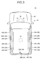
- FIG. 3 is an exemplary view illustrating an example of the vehicle 11 on which the controller 10 is mounted.
- the control unit 16, the storage unit 18, and the communication unit 22 are mounted on a vehicle body 32 (main body part) of the vehicle 11.
- the communication unit 22 performs radio communication with the second terminal 14.
- the communication unit 22 uses a radio communication standard, such as wireless LAN, Bluetooth, or Wi-Fi to perform radio communication with the second terminal 14.
- a plurality of opening/closing bodies 30 are provided in a vehicle body 32 (main body part).
- five opening/closing bodies 30 (30A to 30E) are provided in the vehicle body 32.
- the opening/closing bodies 30A and 30B are each a door disposed at a front side of a side surface of the vehicle 11.
- the opening/closing bodies 30C and 30D are each a door disposed at a rear side of the side surface of the vehicle 11.
- the opening/closing body 30E is a door disposed at a rear side of the vehicle 11 and is a vehicle rear opening/closing door such as a trunk door.
- an opening/closing mode of the opening/closing body 30 is not especially limited as long as at least the opening of the opening/closing body 30 can be achieved by operation of the drive unit 28, and various opening/closing modes, such as a vertical opening/closing mode, an opening/closing mode by a horizontal hinge, and a horizontal sliding opening/closing mode can be adopted.
- the drive unit 28 brings the opening/closing body 30 into an opening or closing motion.
- the drive unit 28 selectively brings at least one of the plurality of opening/closing bodies 30 into an opening or closing motion under control of the control unit 16.
- the imaging unit 26 is a known digital imaging device.
- the imaging unit 26 photographs a peripheral area of the opening/closing body 30 and acquires an image of the peripheral area.
- the image of the peripheral area photographed by the imaging unit 26 may be a moving image obtained by continuously imaging a plurality of frame images. In the present embodiment, it is assumed that the imaging unit 26 photographs the moving image of the peripheral area.
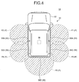
- FIG. 4 is an exemplary view illustrating an imaging range of the imaging unit 26.
- the imaging unit 26 is disposed such that a peripheral area P (peripheral areas P1 to P5 in FIG. 4 ) of the opening/closing body 30 (opening/closing bodies 30A to 30E) provided in the vehicle body 32 is set as the imaging range.
- Each peripheral area P may have a size large enough for the subject 40 positioned in front of each opening/closing body 30 to be photographed.
- the size of each peripheral area P which is the imaging range of the imaging unit 26 may previously be adjusted according to a type of the vehicle body 32.
- controller 10 includes one imaging unit 26.
- the controller 10 may include a plurality of imaging units 26.
- the plurality of imaging units 26 may each be previously adjusted in an installation position and an imaging angle such that the peripheral area P (peripheral areas P1 to P5) of a plurality of the opening/closing bodies 30 (opening/closing bodies 30A to 30E) provided in the vehicle body 32 is set as the imaging range of each of the imaging units 26.
- each of the imaging units 26 is disposed at a position corresponding to the opening/closing body 30 (opening/closing bodies 30A to 30E). Then, the imaging units 26 each photograph the peripheral area P (peripheral areas P1 to P5) of its corresponding opening/closing body 30 (opening/closing bodies 30A to 30E) and acquire a moving image.
- the imaging unit 26 performs imaging using a wide-angle lens so as to acquire the moving image of the peripheral area P.
- the imaging performed by the imaging unit 26 is not limited to imaging using the wide-angle lens.
- the imaging unit 26 since it is only necessary for the imaging unit 26 to be disposed at a position where it can photograph the peripheral area P of the opening/closing body 30, various existing cameras mounted for ensuring safety in the peripheral area of the vehicle 11 may be used as the imaging unit 26.
- various existing cameras mounted for ensuring safety in the peripheral area of the vehicle 11 may be used as the imaging unit 26.
- at least one of on-vehicle cameras e.g., a camera mounted to a side mirror or a fender mirror, a back camera mounted at a rear part of the vehicle 11, a front imaging camera mounted at a front part of the vehicle 11, etc.
- mounted on the vehicle 11 e.g., a camera mounted to a side mirror or a fender mirror, a back camera mounted at a rear part of the vehicle 11, a front imaging camera mounted at a front part of the vehicle 11, etc.
- the reception unit 20 receives the first signal from the first terminal 12.
- the controller 10 includes a plurality of reception units 20 (reception units 20A to 20E).
- the plurality of reception units 20 are provided so as to correspond respectively to the plurality of opening/closing bodies 30 (opening/closing bodies 30A to 30E).
- the plurality of reception units 20 each receive the first signal from the first terminal 12 positioned within a predetermined range from its corresponding opening/closing body 30 (opening/closing bodies 30A to 30E).
- the first signal transmitted from the first terminal 12 is a signal of a strength that can reach the range of the first distance.
- the reception unit 20 becomes ready to receive the first signal from the first terminal 12 when the first terminal 12 is positioned within a range of the first distance from the reception unit 20.
- FIG. 5 is an exemplary view illustrating an arrangement of the reception units 20 and ranges within which the reception units 20 can receive the first signal.
- the reception unit 20A receives the first signal from the first terminal 12 positioned in an area Q1 of a predetermined range from the opening/closing body 30A.
- the reception unit 20A is provided near the opening/closing body 30A (e.g., an upper portion of the opening/closing body 30A of the vehicle body 32) .
- the reception unit 20B receives the first signal from the first terminal 12 positioned in an area Q2 of a predetermined range from the opening/closing body 30B.
- the reception unit 20B is provided near the opening/closing body 30B (e.g., an upper portion of the opening/closing body 30B of the vehicle body 32).
- the reception unit 20C receives the first signal from the first terminal 12 positioned in an area Q3 of a predetermined range from the opening/closing body 30C.
- the reception unit 20C is provided near the opening/closing body 30C (e.g., an upper portion of the opening/closing body 30C of the vehicle body 32).
- the reception unit 20D receives the first signal from the first terminal 12 positioned in an area Q4 of a predetermined range from the opening/closing body 30D.
- the reception unit 20D is provided near the opening/closing body 30D (e.g., an upper portion of the opening/closing body 30D of the vehicle body 32).
- the reception unit 20E receives the first signal from the first terminal 12 positioned in an area Q5 of a predetermined range from the opening/closing body 30E.
- the reception unit 20E is provided near the opening/closing body 30E (e.g., an upper portion of the opening/closing body 30E of the vehicle body 32).
- one of the reception units 20A to 20E that can receive the first signal transmitted from the first terminal 12 receives the first signal from the first terminal 12.
- the area Q (areas Q1 to Q5 each in which the distance from the reception unit 20 is equal to or less than the first distance) within which the first signal can be received by each of the reception units 20A to 20E preferably coincides with the peripheral area P as the imaging range of the imaging unit 26. Further, a size of the area Q within which the first signal can be received by each of the reception units 20A to 20E is preferably smaller than a size of the peripheral area P of the opening/closing body 30 corresponding to each of the reception units 20A to 20E.
- a relative distance between the first terminal 12 and the reception unit 20 that is receiving the first signal from the first terminal 12 changes.
- a reception strength of the first signal at the reception unit 20 changes.
- the strength of the first signal received by each of the reception units 20A to 20E is a strength of a degree that reaches the first distance range and is weaker than a signal transmitted from the second terminal 14.
- the change in the strength of the first signal to be received becomes conspicuous due to the position change of the first terminal 12 within the area Q.
- control unit 16 controls the opening/closing operation of the opening/closing body 30 by using the moving image photographed by the imaging unit 26 and change in the reception strength of the first signal received by the reception unit 20 (details of which will be described later).
- the projection unit 24 projects, to the area Q of a predetermined range from the opening/closing body 30, a guidance image for inducing the subject 40 to perform a predetermined motion.
- the guidance image is, e.g., a linear image or a dot-like image.
- the subject 40 moves his or her body in response to the guidance image and can thereby perform a predetermined motion. Specifically, the subject 40 makes a motion of blocking the linear image or dot-like image as the guidance image or makes a motion along the guidance image and can thereby perform a predetermined motion.
- the projection unit 24 is, e.g., a known projection device such as a projector, a light-emitting device that emits light according to the guidance image, or a light source that emits light according to the guidance image.
- the projection unit 24 projects the projection image to the area Q under control of the control unit 16.
- the storage unit 18 stores various types of information.
- the storage unit 18 is, e.g., an HDD (Hard Disk Drive).
- the storage unit 18 previously stores the first and second information.
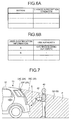
- FIGS. 6A and 6B are views illustrating, as an example, data structures of the first and second information, respectively.
- FIG. 6A is a view illustrating an example of a data structure of the first information.
- the first information is data associating information indicating the motion of the subject 40 with change in the reception strength of the first signal.
- the first information may be provided in the form of a database, but not limited thereto.
- the motion of the subject 40 corresponds to the above-mentioned predetermined motion.
- the motion of the subject 40 is a motion that can be performed even by the subject 40 who has the baggage(s) in both hands (see FIGS. 2A and 2B ).
- Examples of the motion of the subject 40 include, e.g., a motion of the subject 40 moving his or her body upward/downward, a motion of the subject 40 moving his or her body leftward/rightward, a motion of the subject 40 moving his or her body forward/backward (a motion of approaching/separating from the opening/closing body 30 of the vehicle body 32), a motion of the subject 40 moving his or her head, and a motion of the subject 40 moving his or her foot.
- the above-described motions may previously be set on the controller 10. Further, addition or change of the motion may be made by a user operation on an input unit (not illustrated).
- the above-described motions are each preferably a reciprocal motion and, more preferably, a reciprocal motion according to an opening/closing direction of the opening/closing body 30 to be opened/closed.
- the reciprocal motion refers to a repetition of a series of motions in which a motion in a given direction is performed, followed by the same motion in the opposite direction.
- the reciprocal motion is, e.g., a repetition of a series of motions in which the subject 40 spins his or her body to the right, followed by spinning the body to the left.
- the reciprocal motion according to the opening/closing direction of the opening/closing body 30 refers to a reciprocal motion of the subject 40 moving his or her body leftward/rightward when the opening/closing body 30 is a slide type.
- FIG. 7 is an exemplary view illustrating, in an enlarged manner, a rear part of the vehicle body 32.
- the opening/closing body 30 opening/closing body 30E
- the opening/closing body 30E is opened/closed in an arrow X direction of FIG. 7 .
- the reciprocal motion according to the opening/closing direction is, e.g., a motion of the subject 40 in the up/down direction according to the opening/closing direction (arrow X direction) of the opening/closing body 30E.
- the information indicating each motion, stored in the first information is preferably information indicating an analysis result of the moving image of the subject 40 who performs the motion.
- the first information may be information associating identification information of each opening/closing body 30, information indicating the motion of the subject 40, and change in the reception strength.
- the motion corresponding to the identification information of the opening/closing body 30 indicates the motion according to the opening/closing direction of the opening/closing body 30 identified by the identification information.
- the change in the reception strength indicates a change in the reception strength of the first signal transmitted from the first terminal 12 held by the subject 40 at the reception unit 20 occurring when the subject 40 performs the corresponding motion.
- the controller 10 may previously measure the change in the reception strength corresponding to each motion and register a result of the measurement in the first information.
- FIGS. 8A and 8B are graphs illustrating, as an example, a change in a position of the subject 40 and a change in the reception strength, respectively.
- FIG. 8A illustrates an example of the change in the position of the subject 40 and FIG. 8B illustrates an example of the change of the reception strength.
- FIG. 8B is an example of change in the reception strength of the first signal transmitted from the first terminal 12, which has been received by any one reception unit 20 out of the reception units 20A to 20E.
- a detection unit 16C detects a motion of the subject 40 as follows: being positioned in front of the reception unit 20 as viewed from the imaging unit 26 at time t0, being positioned to the right of the reception unit 20 at time t1, being positioned in front of the reception unit 20 once again at time t2, being positioned to the left of the reception unit 20 at time t3, and being positioned in front of the reception unit 20 at time t4.
- a detection method any methods such as an existing object recognition technique and a motion vector analysis can be used.
- the change in the reception strength at the same time is detected as illustrated in FIG. 8B . That is, a high reception strength is detected when the subject 40 is positioned in front of the reception unit 20, and the reception strength becomes lower as the subject 40 moves to the left or right. In short, a positional relationship and a distance between the first terminal 12 held by the subject 40 and the reception unit 20 change with the motion of the subject 40. Thus, the reception strength of the first signal to be received by the reception unit 20 changes in sync with the motion of the subject 40.
- the controller 10 may measure the change in the reception strength of the first signal transmitted from the first terminal 12 held by the subject 40 at the reception unit 20 occurring when the subject 40 performs the corresponding motion in advance and register a result of the measurement in the first information.
- FIG. 6B is a view illustrating an example of a data structure of the second information.
- the second information is data associating user identification information with use authority.
- the second information may be provided in the form of a database, but not limited thereto.
- the user identification information is the same as the user identification information of the second terminal 14 held by the subject 40.
- the use authority is execution authority of various operations of the controller 10, which is given to a user identified by the corresponding user identification information.
- the use authority is, e.g., opening/closing authority for the opening/closing body 30. Note that the use authority is not limited to the opening/closing authority, but may be execution authority of various functions of the vehicle body 32 (main body part) on which the controller 10 is mounted. Further, one or more kinds of use authority may be given for each user identification information.
- control unit 16 is a computer including a CPU (Central Processing Unit) and controls the entire controller 10.
- the control unit 16 may be a circuit other than the CPU.
- the control unit 16 includes an acceptance unit 16A, a projection control unit 16B, a detection unit 16C, an opening/closing control unit 16D, and a main body control unit 16E.
- Some or all of the acceptance unit 16A, the projection control unit 16B, the detection unit 16C, the opening/closing control unit 16D, and the main body control unit 16E may be realized by making a processing unit such as the CPU execute a program, i.e., by software, by hardware such as an IC (Integrated Circuit), or by using software and hardware in combination.
- the control unit 16 may include at least the detection unit 16C and the opening/closing control unit 16D. That is, the control unit 16 may not include at least one of the acceptance unit 16A, the projection control unit 16B and the main body control unit 16E.
- the detection unit 16C detects the motion of the subject 40 included in the moving image acquired by the imaging unit 26.
- the detection unit 16C controls the imaging unit 26 to start imaging when one of the reception units 20 (reception units 20A to 20E) provided in the vehicle body 32 receives the first signal transmitted from the first terminal 12.
- the detection unit 16C activates the imaging unit 26 that covers, as the imaging range, an area Q corresponding to one of the reception units 20 that has received the first signal.
- the imaging unit 26 that covers, as the imaging range, an area Q corresponding to one of the reception units 20 that has the highest reception strength may be activated.
- the detection unit 16C analyzes the moving image acquired by the imaging unit 26 to detect the motion of the subject 40 included in the moving image.
- the detection unit 16C may detect the motion of the subject 40 by using a known image analysis method.
- the opening/closing control unit 16D controls the opening operation of the opening/closing body 30 when the motion of the subject 40 detected by the detection unit 16C and the change of the reception strength of the first signal received by the reception unit 20 change in sync with each other.
- the opening/closing control unit 16D may determine whether or not there is a motion that coincides with the motion of the subject 40 that the detection unit 16C has detected from the moving image among the motions registered in the first information. When there is a motion that coincides with the motion of the subject 40, the opening/closing control unit 16D reads, from the first information, the change in the reception strength corresponding to the motion.
- the opening/closing control unit 16D determines whether or not the change in the reception strength of the first signal received by the reception unit 20 during the motion coincides with the change in the reception strength read from the first information. Note that the opening/closing control unit 16D may determine that the change in the reception strength of the first signal received by the reception unit 20 coincides with the change in the reception strength read from the first information not only when both the changes completely coincide with each other, but also when both the changes have the same regularity in the change in the strength within a predetermined range.
- the opening/closing control unit 16D determines that the change in the reception strength of the first signal received by the reception unit 20 during a predetermined time period in which the subject 40 performs the motion represents a change according to the motion.
- the opening/closing control unit 16D controls the opening operation of the opening/closing body 30.
- the opening/closing control unit 16D controls the opening operation of the opening/closing body 30 when the motion of the subject 40 detected from the moving image of the subject 40 acquired by the imaging unit 26 and change in the reception strength of the first signal received from the first terminal 12 represent the same motion of the subject 40.
- the opening/closing control unit 16D controls the drive unit 28 to bring the opening/closing body 30 to be opened into the opening motion.
- the opening/closing control unit 16D may determine the opening/closing body 30 corresponding to the reception unit 20 that has received the first signal as the opening/closing body 30 to be opened.
- the opening/closing control unit 16D preferably performs control as follows.
- the opening/closing control unit 16D may control the opening operation of the opening/closing body 30 (one of the opening/closing bodies 30A to 30E) that corresponds to the reception unit 20 (one of the reception units 20A to 20E) that has received the first signal. In a case where the plurality of reception units 20 have received the first signal, the opening/closing control unit 16D may determine the opening/closing body 30 corresponding to the reception unit 20 that has the highest reception strength as the opening/closing body 30 to be opened.
- the projection control unit 16B controls, when the first terminal 12 is positioned within a given area Q, the projection unit 24 to project a guidance image to the area Q.
- the projection unit 24 projects the guidance image to the area Q.
- the acceptance unit 16A accepts, when the reception unit 20 receives the first signal, the user identification information from the second terminal 14 through the communication unit 22. When the reception unit 20 has received the first signal, the acceptance unit 16A transmits the user identification acquisition request to the second terminal 14. Upon receiving the acquisition request, the second terminal 14 transmits the user identification information stored in the storage unit 14B to the controller 10. The acceptance unit 16A of the controller 10 accepts the user identification information.
- the opening/closing control unit 16D preferably performs control as follows. That is, the opening/closing control unit 16D determines whether or not the user identification information that has been accepted by the acceptance unit 16A is the user identification information of a user who has the opening/closing authority for the opening/closing body 30. The opening/closing control unit 16D makes this determination by searching the second information (see FIG. 6B ) to determine whether or not the user has the opening/closing authority by determining whether or not the opening/closing authority is included in the use authority corresponding to the accepted user identification information.
- the opening/closing control unit 16D preferably controls the opening operation of the opening/closing body 30.
- the main body control unit 16E controls the main body (in the present embodiment, the vehicle 11) on which the controller 10 is mounted.
- the main body control unit 16E performs known processing of controlling the vehicle 11.
- the main body control unit 16E may be separately provided from the controller 10 in the vehicle 11. In this case, the controller 10 and the main body control unit 16E may be connected to each other so as to be able to exchange data and signals therebetween.
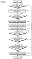
- FIG. 9 is a flowchart illustrating a procedure of control processing executed by the controller 10 according to the present embodiment.
- the detection unit 16C determines whether or not the reception unit 20 has received the first signal (step S100). More in detail, the detection unit 16C determines whether or not one of the plurality of reception units 20 (reception units 20A to 20E) provided in the vehicle body 32 has received the first signal. That is, the detection unit 16C determines whether or not the first terminal 12 is positioned within the area Q within which the reception unit 20 can receive the first signal.
- step S100 When a negative determination is made in step S100 (No in step S100), this routine is ended; on the other hand, when it is determined that the reception unit 20 has received the first signal (Yes in step S100), the procedure proceeds to step S102.
- the acceptance unit 16A accepts the user identification information from the second terminal 14 owned by the subject 40 who holds the first terminal 12 that transmits the first signal that has been received in step S100 (step S102).
- the opening/closing control unit 16D determines whether or not the user identification information accepted in step S102 is the identification information of a user who has the opening/closing authority for the opening/closing body 30 (step S104). When a negative determination is made in step S104 (No in step S104), this routine is ended; on the other hand, when a positive determination is made in step S104 (Yes in step S104), the procedure proceeds to step S106.
- the detection unit 16C controls the imaging unit 26 to start imaging (step S106).
- the detection unit 16C activates the imaging unit 26 that covers, as the imaging range, an area Q corresponding to the reception unit 20 (one of reception units 20A to 20E) that has received the first signal in step S100.
- imaging of the moving image of the peripheral area P of the opening/closing body 30 is started.
- the projection control unit 16B controls the projection unit 24 to project the guidance image to the area Q (step S108).
- the projection control unit 16B controls the projection unit 24 (one of the projection units 24A to 24E) to project the guidance image to the peripheral area P (one of the peripheral areas P1 to P5) of the opening/closing body 30 (one of the opening/closing bodies 30A to 30E) corresponding to the reception unit 20 (one of the reception units 20A to 20E) that has received the first signal in step S100.
- the guidance image is projected to the peripheral area P (one of the peripheral areas P1 to P5) of the opening/closing body 30 (one of the opening/closing bodies 30A to 30E) near the subject 40.
- the subject 40 can easily perform the predetermined motion.
- the detection unit 16C analyzes the moving image acquired by the imaging unit 26 (step S110). Then, the detection unit 16C determines whether or not the motion of the subject 40 has been detected from the moving image (step S112). The detection unit 16C repeatedly makes a negative determination until the motion is detected (No in step S112). When it is determined that the motion has been detected (Yes in step S112), the procedure proceeds to step S114.
- the detection unit 16C determines whether or not information indicating the motion detected in step S112 is the motion that has previously been registered in the first information (step S114).
- the identification information of the opening/closing body 30 information indicating the motion, and change in the reception strength are stored in the first information in association with one other, the following determination is preferably made.
- the detection unit 16C determines whether or not information indicating the motion, which corresponds to the identification information of the opening/closing body 30 (one of the opening/closing bodies 30A to 30E) corresponding to one of the plurality of reception units 20 (any reception units 20A to 20E) that has received the first information in step S100 and information indicating the motion, which is detected in step S112, coincide with each other.
- step S112 When the motion detected in step S112 is not the motion registered in the first information (No in step S114), this routine is ended; on the other hand, when the motion detected in step S112 is the motion registered in the first information (Yes in step S114), the procedure proceeds to step S116.
- step S116 the opening/closing control unit 16D determines whether or not the change in the reception strength of the first signal received by the reception unit 20 (the reception unit 20 that has received the first signal in step S100) during the motion detected in step S112 is the change according to the motion (step S116).
- this routine is ended; on the other hand, when the change in the reception strength of the first signal received by the reception unit 20 is the change according to the motion (Yes in step S116), the procedure proceeds to step S118.
- step S118 the opening/closing control unit 16D controls the opening operation of the opening/closing body 30 (step S118). After that, this routine is ended.
- the opening/closing control unit 16D controls the opening operation of the opening/closing body 30 (one of the opening/closing bodies 30A to 30E) that corresponds to the reception unit 20 (one of the reception units 20A to 20E) that has received the first signal in step S100.
- step S108 and step S114 are omitted in the procedure of the control processing executed by the controller 10 described using FIG. 9 .
- the controller 10 of the present embodiment includes the imaging unit 26, reception unit 20, the detection unit 16C, and the opening/closing control unit 16D.
- the imaging unit 26 acquires the image of the peripheral area P of the opening/closing body 30 provided in the main body part (vehicle body 32).
- the reception unit 20 receives, from the first terminal 12 that transmits the first signal of a predetermined strength, the first signal.
- the detection unit 16C detects the motion of the subject 40 included in the image.
- the opening/closing control unit 16D controls the opening operation of the opening/closing body 30 when the change in the reception strength of the first signal received by the reception unit 20 represents the change synchronizing with the detected motion of the subject 40.
- the controller 10 of the present embodiment detects the motion of the subject 40 from the moving image of the subject 40 positioned within the peripheral area P of the opening/closing body 30 and controls the opening operation of the opening/closing body 30 when the reception strength of the first signal received from the first terminal 12 held by the subject 40 represents the change synchronizing with the detected motion.
- the controller 10 of the present embodiment can prevent occurrence of malfunction of the opening operation of the opening/closing body 30.
- the controller 10 can open the opening/closing body 30 while preventing the malfunction.
- controller 10 preferably includes the projection unit 24 and the projection control unit 16B. With this configuration, it is possible to induce the subject 40 to perform a predetermined motion.
- the controller 10 accepts the user identification information from the second terminal 14 when the reception unit 20 receives the first signal.
- the opening/closing control unit 16D controls the opening operation of the opening/closing body 30 when the accepted user identification information is the user identification information of a user who has the opening/closing authority for the opening/closing body 30, when the predetermined motion of the subject 40 is detected, and when the reception strength of the first signal represents a change according to the motion.
- the controller 10 can prevent the malfunction of the opening operation for the opening/closing body 30 more effectively and can enhance security.
- the predetermined motion is preferably a motion according to the opening/closing direction of the opening/closing body 30 to be opened/closed.
- the controller 10 can enhance convenience of the subject 40 in controlling the opening operation.
- the opening/closing control unit 16D controls the opening operation of the opening/closing body 30 corresponding to the reception unit 20 that has received the first signal when the predetermined motion of the subject 40 is detected, and when the reception strength of the first signal represents a change according to the motion.
- the controller 10 can selectively open one of the plurality of opening/closing bodies 30 (opening/closing bodies 30A to 30E) in front of which the subject 40 is positioned.
- the controller 10 is mounted on the vehicle 11.
- the mounting object on which the controller 10 is mounted is not limited to the vehicle 11, but may be any object having the opening/closing body 30.
- the controller 10 may be provided in a building having the opening/closing body 30, an area having the opening/closing body 30 (e.g., parking area having the opening/closing body 30 at a gateway), or the like.
- FIG. 10 is a block diagram illustrating a hardware configuration example of each of the controller 10, the first terminal 12, and the second terminal 14 according to the above embodiment.
- the controller 10, the first terminal 12, and the second terminal 14 each have a hardware configuration using an ordinary computer, in which a communication I/F 60, a CPU 62, a ROM 64, a RAM 66, and an HDD 68 are connected to one another by a bus 70.
- the CPU 62 is an arithmetic unit that controls the entire processing of each of the controller 10, the first terminal 12, and the second terminal 14 according to the above embodiment.
- the RAM 66 stores data required for the CPU 62 to perform various processing.
- the ROM 64 stores a program for realizing various processing to be performed by the CPU 62.
- the HDD 68 stores data to be stored in the above-mentioned storage unit 18 or storage unit 14B.
- the communication I/F 60 is an interface connected to an external device or an external terminal through a communication line so as to exchange data with the connected external device or external terminal.
- a program for executing the search processing to be executed in each of the controller 10, the first terminal 12, and the second terminal 14 according to the above embodiment may be provided by being previously implemented in the ROM 64.
- the program for executing the above processing to be executed in each of the controller 10, the first terminal 12, and the second terminal 14 according to the above embodiment may be provided by being recorded in an installable form or an executable form in a computer readable storage medium, such as a CD-ROM, a flexible disk (FD), a CD-R, a DVD (Digital Versatile Disk), or the like.
- a computer readable storage medium such as a CD-ROM, a flexible disk (FD), a CD-R, a DVD (Digital Versatile Disk), or the like.
- the program for executing the above processing to be executed in each of the controller 10, the first terminal 12, and the second terminal 14 according to the above embodiment may be provided by being stored in a computer connected to a network such as Internet and downloaded over the network. Further alternatively, the program for executing the above processing to be executed in each of the controller 10, the first terminal 12, and the second terminal 14 according to the above embodiment may be provided or distributed over a network such as Internet.
- the program for executing the above processing to be executed in each of the controller 10, the first terminal 12, and the second terminal 14 according to the above embodiment has a module structure made up of the above-described units.
- the CPU 62 reads the program for executing the above processing from a storage medium such as the ROM 64 and executes the program to load the units on a main memory, thereby generating the above units on the main memory.
Applications Claiming Priority (1)
| Application Number | Priority Date | Filing Date | Title |
|---|---|---|---|
| JP2014234561A JP6281474B2 (ja) | 2014-11-19 | 2014-11-19 | 制御装置、制御方法、および制御プログラム |
Publications (2)
| Publication Number | Publication Date |
|---|---|
| EP3023943A1 true EP3023943A1 (de) | 2016-05-25 |
| EP3023943B1 EP3023943B1 (de) | 2018-07-25 |
Family
ID=54705379
Family Applications (1)
| Application Number | Title | Priority Date | Filing Date |
|---|---|---|---|
| EP15195210.8A Active EP3023943B1 (de) | 2014-11-19 | 2015-11-18 | Steuerung, steuerungsverfahren und computerlesbares aufzeichnungsmedium |
Country Status (4)
| Country | Link |
|---|---|
| US (1) | US10465429B2 (de) |
| EP (1) | EP3023943B1 (de) |
| JP (1) | JP6281474B2 (de) |
| CN (1) | CN105599724B (de) |
Cited By (1)
| Publication number | Priority date | Publication date | Assignee | Title |
|---|---|---|---|---|
| WO2017220774A1 (de) * | 2016-06-24 | 2017-12-28 | Brose Fahrzeugteile Gmbh & Co. Kommanditgesellschaft, Bamberg | Verfahren zu ansteuerung einer motorischen verschlusselementanordnung eines kraftfahrzeuges |
Families Citing this family (6)
| Publication number | Priority date | Publication date | Assignee | Title |
|---|---|---|---|---|
| JP6520800B2 (ja) * | 2015-12-23 | 2019-05-29 | 株式会社Soken | 乗員情報取得システム |
| CN108204187A (zh) * | 2016-12-19 | 2018-06-26 | 大众汽车(中国)投资有限公司 | 用于开启车辆的后备箱的方法和装置 |
| JP6879113B2 (ja) * | 2017-08-04 | 2021-06-02 | トヨタ自動車株式会社 | 端末装置、認証システムおよび認証制御方法 |
| JP2018096202A (ja) * | 2018-01-22 | 2018-06-21 | 株式会社Jvcケンウッド | 制御装置、制御方法、および制御プログラム |
| CN110239485B (zh) * | 2019-06-28 | 2021-11-16 | 无锡睿勤科技有限公司 | 车辆及车载进入方法 |
| JP7411420B2 (ja) * | 2020-01-15 | 2024-01-11 | 本田技研工業株式会社 | 車両制御装置及び開閉体動作方法 |
Citations (8)
| Publication number | Priority date | Publication date | Assignee | Title |
|---|---|---|---|---|
| JP2005315024A (ja) | 2004-04-30 | 2005-11-10 | Fujitsu Ten Ltd | 車両制御装置 |
| DE102006037237A1 (de) * | 2006-08-09 | 2008-02-14 | Siemens Ag | Verfahren zum Steuern einer Tür eines Fahrzeugs |
| DE102008021989A1 (de) * | 2008-05-02 | 2008-12-18 | Daimler Ag | Vorrichtung zum Ver- und Entriegeln einer mittels eines elektronischen Zugangsberechtigungssystems gesicherten Fahrzeugtür für ein Fahrzeug |
| US20110248820A1 (en) * | 2008-10-01 | 2011-10-13 | Valeo Securite Habitacle | Device for automatically unlocking an openable panel of a motor vehicle |
| US20120249291A1 (en) * | 2011-03-29 | 2012-10-04 | Denso Corporation | Systems and methods for vehicle passive entry |
| JP2013117134A (ja) | 2011-12-05 | 2013-06-13 | Suzuki Motor Corp | 後部開閉体の開閉制御システム |
| WO2013082725A1 (en) * | 2011-12-09 | 2013-06-13 | Flextronics Automotive Inc. | Modular automotive camera and image processing system for automated portal entry |
| WO2014041955A1 (ja) * | 2012-09-12 | 2014-03-20 | 日産自動車株式会社 | 車両開閉体の制御装置 |
Family Cites Families (6)
| Publication number | Priority date | Publication date | Assignee | Title |
|---|---|---|---|---|
| FR2880167B1 (fr) * | 2004-12-23 | 2009-05-08 | Celec Conception Electronique | Procede de detection de presence et de mouvement pour des automatismes de porte et automatismes de porte mettant en oeuvre un tel procede |
| US8016148B2 (en) * | 2006-07-12 | 2011-09-13 | Rexam Beverage Can Company | Necked-in can body and method for making same |
| US8287004B2 (en) * | 2009-07-30 | 2012-10-16 | Pitney Bowes Inc. | Reusable windowed envelope |
| JP5643129B2 (ja) * | 2011-02-07 | 2014-12-17 | 株式会社アルファ | 車両の扉体制御装置 |
| DE102011018847A1 (de) * | 2011-04-27 | 2012-10-31 | Brose Fahrzeugteile Gmbh & Co. Kommanditgesellschaft, Hallstadt | Verfahren zur Ansteuerung einer Verschlusselementanordnung eines Kraftfahrzeugs |
| US8994229B2 (en) * | 2011-12-14 | 2015-03-31 | Optex Inc. | Wireless non-contact switch for automatic doors |
-
2014
- 2014-11-19 JP JP2014234561A patent/JP6281474B2/ja active Active
-
2015
- 2015-10-15 CN CN201510666767.2A patent/CN105599724B/zh active Active
- 2015-11-16 US US14/942,545 patent/US10465429B2/en active Active
- 2015-11-18 EP EP15195210.8A patent/EP3023943B1/de active Active
Patent Citations (9)
| Publication number | Priority date | Publication date | Assignee | Title |
|---|---|---|---|---|
| JP2005315024A (ja) | 2004-04-30 | 2005-11-10 | Fujitsu Ten Ltd | 車両制御装置 |
| DE102006037237A1 (de) * | 2006-08-09 | 2008-02-14 | Siemens Ag | Verfahren zum Steuern einer Tür eines Fahrzeugs |
| DE102008021989A1 (de) * | 2008-05-02 | 2008-12-18 | Daimler Ag | Vorrichtung zum Ver- und Entriegeln einer mittels eines elektronischen Zugangsberechtigungssystems gesicherten Fahrzeugtür für ein Fahrzeug |
| US20110248820A1 (en) * | 2008-10-01 | 2011-10-13 | Valeo Securite Habitacle | Device for automatically unlocking an openable panel of a motor vehicle |
| US20120249291A1 (en) * | 2011-03-29 | 2012-10-04 | Denso Corporation | Systems and methods for vehicle passive entry |
| JP2013117134A (ja) | 2011-12-05 | 2013-06-13 | Suzuki Motor Corp | 後部開閉体の開閉制御システム |
| WO2013082725A1 (en) * | 2011-12-09 | 2013-06-13 | Flextronics Automotive Inc. | Modular automotive camera and image processing system for automated portal entry |
| WO2014041955A1 (ja) * | 2012-09-12 | 2014-03-20 | 日産自動車株式会社 | 車両開閉体の制御装置 |
| EP2896770A1 (de) * | 2012-09-12 | 2015-07-22 | Nissan Motor Co., Ltd. | Steuerungsvorrichtung zum öffnen/schliessen von fahrzeugelementen |
Cited By (1)
| Publication number | Priority date | Publication date | Assignee | Title |
|---|---|---|---|---|
| WO2017220774A1 (de) * | 2016-06-24 | 2017-12-28 | Brose Fahrzeugteile Gmbh & Co. Kommanditgesellschaft, Bamberg | Verfahren zu ansteuerung einer motorischen verschlusselementanordnung eines kraftfahrzeuges |
Also Published As
| Publication number | Publication date |
|---|---|
| CN105599724B (zh) | 2020-03-27 |
| EP3023943B1 (de) | 2018-07-25 |
| CN105599724A (zh) | 2016-05-25 |
| US10465429B2 (en) | 2019-11-05 |
| US20160138318A1 (en) | 2016-05-19 |
| JP2016098516A (ja) | 2016-05-30 |
| JP6281474B2 (ja) | 2018-02-21 |
Similar Documents
| Publication | Publication Date | Title |
|---|---|---|
| EP3023943B1 (de) | Steuerung, steuerungsverfahren und computerlesbares aufzeichnungsmedium | |
| EP3109117B1 (de) | Vorrichtung und verfahren zum öffnen des kofferraum eines kraftfahrzeuges und aufzeichnungsmedium zum aufzeichnen des programms zur ausführung des verfahrens | |
| CN106960486B (zh) | 通过手势识别和语音命令进行功能特性激活的系统和方法 | |
| CN109564730B (zh) | 车辆和控制方法 | |
| KR100887688B1 (ko) | 핸드 셰이프에 의한 도어개폐 제어장치 | |
| JP2017043267A5 (de) | ||
| JP6182482B2 (ja) | 制御装置および制御システム | |
| US10311313B2 (en) | In-vehicle passive entry lighting control system | |
| JP6207089B2 (ja) | 車両ドア制御装置 | |
| US20220316260A1 (en) | Trunk Control Method and Apparatus, and Storage Medium | |
| CN113799729A (zh) | 车辆控制系统及车辆控制方法 | |
| JP2013036251A (ja) | 車載カメラと携帯情報端末機による車両開閉体操作装置及びシステム並びにその制御方法 | |
| JP7147259B2 (ja) | 車載装置、車載装置の制御方法、及び予備動作推定システム | |
| US20220089127A1 (en) | Information processing apparatus, program, computer readable recording medium, and information processing method | |
| JP2011172195A (ja) | 車載機、携帯機器、および制御プログラム | |
| JP2020057139A (ja) | 機器制御装置 | |
| US20190098127A1 (en) | Driver device locking | |
| US20210370867A1 (en) | Vehicle control system, server, and vehicle control method | |
| CN113494229B (zh) | 车辆控制装置、车辆控制方法及记录介质 | |
| JP2018096202A (ja) | 制御装置、制御方法、および制御プログラム | |
| CN112937479A (zh) | 车辆控制方法及装置、电子设备和存储介质 | |
| JP2021188295A (ja) | 車両制御システム、及び車両制御方法 | |
| JP2021127575A (ja) | 車両制御装置、車両制御方法、及び車両制御用プログラム | |
| JP2016055789A (ja) | 車両用認証装置 | |
| WO2023210433A1 (ja) | 異常検出システム及び異常検出方法 |
Legal Events
| Date | Code | Title | Description |
|---|---|---|---|
| AK | Designated contracting states |
Kind code of ref document: A1 Designated state(s): AL AT BE BG CH CY CZ DE DK EE ES FI FR GB GR HR HU IE IS IT LI LT LU LV MC MK MT NL NO PL PT RO RS SE SI SK SM TR |
|
| AX | Request for extension of the european patent |
Extension state: BA ME |
|
| PUAI | Public reference made under article 153(3) epc to a published international application that has entered the european phase |
Free format text: ORIGINAL CODE: 0009012 |
|
| 17P | Request for examination filed |
Effective date: 20161125 |
|
| RBV | Designated contracting states (corrected) |
Designated state(s): AL AT BE BG CH CY CZ DE DK EE ES FI FR GB GR HR HU IE IS IT LI LT LU LV MC MK MT NL NO PL PT RO RS SE SI SK SM TR |
|
| 17Q | First examination report despatched |
Effective date: 20170317 |
|
| GRAP | Despatch of communication of intention to grant a patent |
Free format text: ORIGINAL CODE: EPIDOSNIGR1 |
|
| INTG | Intention to grant announced |
Effective date: 20180219 |
|
| GRAS | Grant fee paid |
Free format text: ORIGINAL CODE: EPIDOSNIGR3 |
|
| GRAA | (expected) grant |
Free format text: ORIGINAL CODE: 0009210 |
|
| AK | Designated contracting states |
Kind code of ref document: B1 Designated state(s): AL AT BE BG CH CY CZ DE DK EE ES FI FR GB GR HR HU IE IS IT LI LT LU LV MC MK MT NL NO PL PT RO RS SE SI SK SM TR |
|
| REG | Reference to a national code |
Ref country code: GB Ref legal event code: FG4D |
|
| REG | Reference to a national code |
Ref country code: CH Ref legal event code: EP |
|
| REG | Reference to a national code |
Ref country code: AT Ref legal event code: REF Ref document number: 1022581 Country of ref document: AT Kind code of ref document: T Effective date: 20180815 |
|
| REG | Reference to a national code |
Ref country code: IE Ref legal event code: FG4D |
|
| REG | Reference to a national code |
Ref country code: DE Ref legal event code: R096 Ref document number: 602015013930 Country of ref document: DE |
|
| REG | Reference to a national code |
Ref country code: NL Ref legal event code: MP Effective date: 20180725 |
|
| REG | Reference to a national code |
Ref country code: LT Ref legal event code: MG4D |
|
| PG25 | Lapsed in a contracting state [announced via postgrant information from national office to epo] |
Ref country code: NL Free format text: LAPSE BECAUSE OF FAILURE TO SUBMIT A TRANSLATION OF THE DESCRIPTION OR TO PAY THE FEE WITHIN THE PRESCRIBED TIME-LIMIT Effective date: 20180725 |
|
| REG | Reference to a national code |
Ref country code: AT Ref legal event code: MK05 Ref document number: 1022581 Country of ref document: AT Kind code of ref document: T Effective date: 20180725 |
|
| PG25 | Lapsed in a contracting state [announced via postgrant information from national office to epo] |
Ref country code: LT Free format text: LAPSE BECAUSE OF FAILURE TO SUBMIT A TRANSLATION OF THE DESCRIPTION OR TO PAY THE FEE WITHIN THE PRESCRIBED TIME-LIMIT Effective date: 20180725 Ref country code: BG Free format text: LAPSE BECAUSE OF FAILURE TO SUBMIT A TRANSLATION OF THE DESCRIPTION OR TO PAY THE FEE WITHIN THE PRESCRIBED TIME-LIMIT Effective date: 20181025 Ref country code: RS Free format text: LAPSE BECAUSE OF FAILURE TO SUBMIT A TRANSLATION OF THE DESCRIPTION OR TO PAY THE FEE WITHIN THE PRESCRIBED TIME-LIMIT Effective date: 20180725 Ref country code: IS Free format text: LAPSE BECAUSE OF FAILURE TO SUBMIT A TRANSLATION OF THE DESCRIPTION OR TO PAY THE FEE WITHIN THE PRESCRIBED TIME-LIMIT Effective date: 20181125 Ref country code: SE Free format text: LAPSE BECAUSE OF FAILURE TO SUBMIT A TRANSLATION OF THE DESCRIPTION OR TO PAY THE FEE WITHIN THE PRESCRIBED TIME-LIMIT Effective date: 20180725 Ref country code: NO Free format text: LAPSE BECAUSE OF FAILURE TO SUBMIT A TRANSLATION OF THE DESCRIPTION OR TO PAY THE FEE WITHIN THE PRESCRIBED TIME-LIMIT Effective date: 20181025 Ref country code: AT Free format text: LAPSE BECAUSE OF FAILURE TO SUBMIT A TRANSLATION OF THE DESCRIPTION OR TO PAY THE FEE WITHIN THE PRESCRIBED TIME-LIMIT Effective date: 20180725 Ref country code: PL Free format text: LAPSE BECAUSE OF FAILURE TO SUBMIT A TRANSLATION OF THE DESCRIPTION OR TO PAY THE FEE WITHIN THE PRESCRIBED TIME-LIMIT Effective date: 20180725 Ref country code: FI Free format text: LAPSE BECAUSE OF FAILURE TO SUBMIT A TRANSLATION OF THE DESCRIPTION OR TO PAY THE FEE WITHIN THE PRESCRIBED TIME-LIMIT Effective date: 20180725 Ref country code: GR Free format text: LAPSE BECAUSE OF FAILURE TO SUBMIT A TRANSLATION OF THE DESCRIPTION OR TO PAY THE FEE WITHIN THE PRESCRIBED TIME-LIMIT Effective date: 20181026 |
|
| PG25 | Lapsed in a contracting state [announced via postgrant information from national office to epo] |
Ref country code: AL Free format text: LAPSE BECAUSE OF FAILURE TO SUBMIT A TRANSLATION OF THE DESCRIPTION OR TO PAY THE FEE WITHIN THE PRESCRIBED TIME-LIMIT Effective date: 20180725 Ref country code: HR Free format text: LAPSE BECAUSE OF FAILURE TO SUBMIT A TRANSLATION OF THE DESCRIPTION OR TO PAY THE FEE WITHIN THE PRESCRIBED TIME-LIMIT Effective date: 20180725 Ref country code: LV Free format text: LAPSE BECAUSE OF FAILURE TO SUBMIT A TRANSLATION OF THE DESCRIPTION OR TO PAY THE FEE WITHIN THE PRESCRIBED TIME-LIMIT Effective date: 20180725 |
|
| REG | Reference to a national code |
Ref country code: DE Ref legal event code: R097 Ref document number: 602015013930 Country of ref document: DE |
|
| PG25 | Lapsed in a contracting state [announced via postgrant information from national office to epo] |
Ref country code: EE Free format text: LAPSE BECAUSE OF FAILURE TO SUBMIT A TRANSLATION OF THE DESCRIPTION OR TO PAY THE FEE WITHIN THE PRESCRIBED TIME-LIMIT Effective date: 20180725 Ref country code: IT Free format text: LAPSE BECAUSE OF FAILURE TO SUBMIT A TRANSLATION OF THE DESCRIPTION OR TO PAY THE FEE WITHIN THE PRESCRIBED TIME-LIMIT Effective date: 20180725 Ref country code: RO Free format text: LAPSE BECAUSE OF FAILURE TO SUBMIT A TRANSLATION OF THE DESCRIPTION OR TO PAY THE FEE WITHIN THE PRESCRIBED TIME-LIMIT Effective date: 20180725 Ref country code: CZ Free format text: LAPSE BECAUSE OF FAILURE TO SUBMIT A TRANSLATION OF THE DESCRIPTION OR TO PAY THE FEE WITHIN THE PRESCRIBED TIME-LIMIT Effective date: 20180725 Ref country code: ES Free format text: LAPSE BECAUSE OF FAILURE TO SUBMIT A TRANSLATION OF THE DESCRIPTION OR TO PAY THE FEE WITHIN THE PRESCRIBED TIME-LIMIT Effective date: 20180725 |
|
| PG25 | Lapsed in a contracting state [announced via postgrant information from national office to epo] |
Ref country code: SM Free format text: LAPSE BECAUSE OF FAILURE TO SUBMIT A TRANSLATION OF THE DESCRIPTION OR TO PAY THE FEE WITHIN THE PRESCRIBED TIME-LIMIT Effective date: 20180725 Ref country code: SK Free format text: LAPSE BECAUSE OF FAILURE TO SUBMIT A TRANSLATION OF THE DESCRIPTION OR TO PAY THE FEE WITHIN THE PRESCRIBED TIME-LIMIT Effective date: 20180725 Ref country code: DK Free format text: LAPSE BECAUSE OF FAILURE TO SUBMIT A TRANSLATION OF THE DESCRIPTION OR TO PAY THE FEE WITHIN THE PRESCRIBED TIME-LIMIT Effective date: 20180725 |
|
| PLBE | No opposition filed within time limit |
Free format text: ORIGINAL CODE: 0009261 |
|
| STAA | Information on the status of an ep patent application or granted ep patent |
Free format text: STATUS: NO OPPOSITION FILED WITHIN TIME LIMIT |
|
| REG | Reference to a national code |
Ref country code: CH Ref legal event code: PL |
|
| 26N | No opposition filed |
Effective date: 20190426 |
|
| PG25 | Lapsed in a contracting state [announced via postgrant information from national office to epo] |
Ref country code: LU Free format text: LAPSE BECAUSE OF NON-PAYMENT OF DUE FEES Effective date: 20181118 Ref country code: MC Free format text: LAPSE BECAUSE OF FAILURE TO SUBMIT A TRANSLATION OF THE DESCRIPTION OR TO PAY THE FEE WITHIN THE PRESCRIBED TIME-LIMIT Effective date: 20180725 |
|
| REG | Reference to a national code |
Ref country code: BE Ref legal event code: MM Effective date: 20181130 |
|
| REG | Reference to a national code |
Ref country code: IE Ref legal event code: MM4A |
|
| PG25 | Lapsed in a contracting state [announced via postgrant information from national office to epo] |
Ref country code: SI Free format text: LAPSE BECAUSE OF FAILURE TO SUBMIT A TRANSLATION OF THE DESCRIPTION OR TO PAY THE FEE WITHIN THE PRESCRIBED TIME-LIMIT Effective date: 20180725 Ref country code: LI Free format text: LAPSE BECAUSE OF NON-PAYMENT OF DUE FEES Effective date: 20181130 Ref country code: CH Free format text: LAPSE BECAUSE OF NON-PAYMENT OF DUE FEES Effective date: 20181130 |
|
| PG25 | Lapsed in a contracting state [announced via postgrant information from national office to epo] |
Ref country code: IE Free format text: LAPSE BECAUSE OF NON-PAYMENT OF DUE FEES Effective date: 20181118 Ref country code: FR Free format text: LAPSE BECAUSE OF NON-PAYMENT OF DUE FEES Effective date: 20181130 |
|
| PG25 | Lapsed in a contracting state [announced via postgrant information from national office to epo] |
Ref country code: BE Free format text: LAPSE BECAUSE OF NON-PAYMENT OF DUE FEES Effective date: 20181130 |
|
| PG25 | Lapsed in a contracting state [announced via postgrant information from national office to epo] |
Ref country code: MT Free format text: LAPSE BECAUSE OF NON-PAYMENT OF DUE FEES Effective date: 20181118 |
|
| PG25 | Lapsed in a contracting state [announced via postgrant information from national office to epo] |
Ref country code: TR Free format text: LAPSE BECAUSE OF FAILURE TO SUBMIT A TRANSLATION OF THE DESCRIPTION OR TO PAY THE FEE WITHIN THE PRESCRIBED TIME-LIMIT Effective date: 20180725 |
|
| PG25 | Lapsed in a contracting state [announced via postgrant information from national office to epo] |
Ref country code: PT Free format text: LAPSE BECAUSE OF FAILURE TO SUBMIT A TRANSLATION OF THE DESCRIPTION OR TO PAY THE FEE WITHIN THE PRESCRIBED TIME-LIMIT Effective date: 20180725 |
|
| PG25 | Lapsed in a contracting state [announced via postgrant information from national office to epo] |
Ref country code: HU Free format text: LAPSE BECAUSE OF FAILURE TO SUBMIT A TRANSLATION OF THE DESCRIPTION OR TO PAY THE FEE WITHIN THE PRESCRIBED TIME-LIMIT; INVALID AB INITIO Effective date: 20151118 Ref country code: CY Free format text: LAPSE BECAUSE OF FAILURE TO SUBMIT A TRANSLATION OF THE DESCRIPTION OR TO PAY THE FEE WITHIN THE PRESCRIBED TIME-LIMIT Effective date: 20180725 Ref country code: MK Free format text: LAPSE BECAUSE OF NON-PAYMENT OF DUE FEES Effective date: 20180725 |
|
| GBPC | Gb: european patent ceased through non-payment of renewal fee |
Effective date: 20191118 |
|
| PG25 | Lapsed in a contracting state [announced via postgrant information from national office to epo] |
Ref country code: GB Free format text: LAPSE BECAUSE OF NON-PAYMENT OF DUE FEES Effective date: 20191118 |
|
| PGFP | Annual fee paid to national office [announced via postgrant information from national office to epo] |
Ref country code: DE Payment date: 20230929 Year of fee payment: 9 |