EP3022057B1 - Printing assembly - Google Patents
Printing assembly Download PDFInfo
- Publication number
- EP3022057B1 EP3022057B1 EP14826777.6A EP14826777A EP3022057B1 EP 3022057 B1 EP3022057 B1 EP 3022057B1 EP 14826777 A EP14826777 A EP 14826777A EP 3022057 B1 EP3022057 B1 EP 3022057B1
- Authority
- EP
- European Patent Office
- Prior art keywords
- axial
- oppositely
- cylinder
- axial end
- clamping
- Prior art date
- Legal status (The legal status is an assumption and is not a legal conclusion. Google has not performed a legal analysis and makes no representation as to the accuracy of the status listed.)
- Active
Links
- 230000006835 compression Effects 0.000 claims description 9
- 238000007906 compression Methods 0.000 claims description 9
- 230000007704 transition Effects 0.000 claims description 4
- 230000004323 axial length Effects 0.000 claims 2
- 230000005291 magnetic effect Effects 0.000 description 6
- 230000005294 ferromagnetic effect Effects 0.000 description 3
- 238000009434 installation Methods 0.000 description 3
- 230000000712 assembly Effects 0.000 description 2
- 238000000429 assembly Methods 0.000 description 2
- 238000007789 sealing Methods 0.000 description 2
- 229910000831 Steel Inorganic materials 0.000 description 1
- 238000004026 adhesive bonding Methods 0.000 description 1
- 230000009286 beneficial effect Effects 0.000 description 1
- 230000007812 deficiency Effects 0.000 description 1
- 230000001419 dependent effect Effects 0.000 description 1
- 230000002708 enhancing effect Effects 0.000 description 1
- 238000003780 insertion Methods 0.000 description 1
- 230000037431 insertion Effects 0.000 description 1
- 230000005298 paramagnetic effect Effects 0.000 description 1
- 230000000717 retained effect Effects 0.000 description 1
- 125000006850 spacer group Chemical group 0.000 description 1
- 239000010959 steel Substances 0.000 description 1
Images


Classifications
-
- B—PERFORMING OPERATIONS; TRANSPORTING
- B41—PRINTING; LINING MACHINES; TYPEWRITERS; STAMPS
- B41F—PRINTING MACHINES OR PRESSES
- B41F27/00—Devices for attaching printing elements or formes to supports
- B41F27/02—Magnetic devices
-
- B—PERFORMING OPERATIONS; TRANSPORTING
- B41—PRINTING; LINING MACHINES; TYPEWRITERS; STAMPS
- B41F—PRINTING MACHINES OR PRESSES
- B41F27/00—Devices for attaching printing elements or formes to supports
- B41F27/12—Devices for attaching printing elements or formes to supports for attaching flexible printing formes
-
- B—PERFORMING OPERATIONS; TRANSPORTING
- B41—PRINTING; LINING MACHINES; TYPEWRITERS; STAMPS
- B41F—PRINTING MACHINES OR PRESSES
- B41F13/00—Common details of rotary presses or machines
- B41F13/08—Cylinders
- B41F13/10—Forme cylinders
-
- B—PERFORMING OPERATIONS; TRANSPORTING
- B41—PRINTING; LINING MACHINES; TYPEWRITERS; STAMPS
- B41F—PRINTING MACHINES OR PRESSES
- B41F13/00—Common details of rotary presses or machines
- B41F13/08—Cylinders
- B41F13/20—Supports for bearings or supports for forme, offset, or impression cylinders
-
- B—PERFORMING OPERATIONS; TRANSPORTING
- B41—PRINTING; LINING MACHINES; TYPEWRITERS; STAMPS
- B41F—PRINTING MACHINES OR PRESSES
- B41F27/00—Devices for attaching printing elements or formes to supports
- B41F27/10—Devices for attaching printing elements or formes to supports for attaching non-deformable curved printing formes to forme cylinders
- B41F27/105—Devices for attaching printing elements or formes to supports for attaching non-deformable curved printing formes to forme cylinders for attaching cylindrical printing formes
-
- B—PERFORMING OPERATIONS; TRANSPORTING
- B41—PRINTING; LINING MACHINES; TYPEWRITERS; STAMPS
- B41F—PRINTING MACHINES OR PRESSES
- B41F27/00—Devices for attaching printing elements or formes to supports
- B41F27/14—Devices for attaching printing elements or formes to supports for attaching printing formes to intermediate supports, e.g. adapter members
Definitions
- This invention relates to magnetic print rolls and print cylinder assemblies which include multiplicities of embedded magnets within their outer circumferential surfaces. More particularly, this invention relates to such rolls and cylinders which are adapted for attachment to and detachment from print roll receiving and driving axles.
- Magnetic print rolls or cylinders commonly include configurations of the walls of their interior axle receiving bores which facilitate attachments to and detachments from print roll receiving and driving axles.
- Such interior bore wall structures commonly inefficiently and in a mechanically cumbersome manner facilitate attachments of the cylinder to driving axles and detachments therefrom.
- the instant inventive printing assembly solves or ameliorates such problems and deficiencies by specially configuring the cylinder's axle receiving bore wall for ease in installation upon and deinstallation from a cylinder driving axle and for ease and efficiency in rigidly locking the cylinder thereon, and for unlocking the cylinder therefrom.
- US 1 674 635 A discloses a printing assembly comprising a cylinder having a tiered wall and means for clamping the cylinder to a shaft and for attaching end covers to the cylinder.
- a first structural component of the printing assembly comprises a clamping annulus which has a tiered circumferential end or tiered outer circumferential aspect.
- Such clamping annulus necessarily has axially and oppositely axial ends, each such end having an outside diameter.
- the outside diameter of the clamping annulus's axial end is greater than or exceeds the outside diameter of the clamping annulus's oppositely axial end.
- Such diameter differential advantageously results in stepping or tiering of the clamping annulus, and such dimensional difference advantageously forms and defines a guide sleeve receiving space within and as a part of the axial end of the clamping annulus.
- a further structural component of the printing assembly comprises a cylinder or roll which, like the assembly's clamping annulus, has axial and oppositely axial ends.
- the assembly's cylinder component has a cylindrically configured circumferential outer surface, and the cylinder has a bore which is defined by a tiered inner wall.
- the cylinder's tiered inner wall has axially and oppositely axial ends. The axial end of the cylinder's tiered inner wall circumferentially and radially outwardly overlies the clamping annulus's axial end, and such wall's oppositely axial end correspondingly circumferentially and radially outwardly overlies the clamping annuluses oppositely axial end.
- a further structural component of the print assembly comprises a plurality of magnet receiving recesses, each recess among the plurality of magnet receiving recesses preferably extending radially inwardly into the cylinder from the cylinder's outer circumferential surface.
- Pluralities of permanent magnets and magnetic strengthen enhancing pole pieces are fixedly embedded within the magnet receiving recesses for secure attachment and holding of flexible ferro-magnetic print dies.
- the guide sleeve receiving space which is formed and defined within the clamping annulus and which is radially outwardly bounded by the axial end of the cylinder's tiered inner wall allows for convenient and mechanically efficient operation therein of an annular wedge clamp.
- clamp jaws and sleeve configured wedges may be forcefully moved along and driven between the cylinder's bore wall and a drive axle which extends axially through the cylinder bore.
- Such wedge driving clamping action is advantageously facilitated by the tiered clamping annulus.
- the clamping annulus is further specially configured to present an annular land or radial transition which effectively divides the clamping annulus's axial and oppositely axial ends.
- Closely fitted axial and oppositely axial compression rings are preferably fixedly mounted to the cylinder at axial and oppositely axial ends of the cylinder bore's tiered inner wall.
- such compression rings are mounted thereon at axial and oppositely axial sides of a cross-sectional plane which substantially bisects the cylinder's axial dimension.
- the present invention seeks to include the provision of a printing assembly which incorporates components, as described above, and which arranges such components in relationship to each other in manners described above for the performance of and achievement of beneficial objects, as described above.
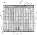
- a preferred embodiment of the instant inventive printing assembly includes a cylinder or roll component which is referred to generally by Reference Arrow 1.
- the cylinder 1 has an outer circumferential surface comprising radially outer aspects of ridges 10 and axial and oppositely axial cylinder surfaces 7 and 8 situated at the cylinder's axial and oppositely axial ends 16 and 18.
- the cylinder ends 7 and 8, and axially extending ridges 10 in combination with outer surfaces 6 of the cylinder's body 3 advantageously form a plurality of magnet and magnetic pole pieces receiving recesses 2,4.
- Multiplicities of magnets 12, and mild paramagnetic steel pole pieces 14 are preferably fixedly embedded via adhesive bonding within the recesses 2,4, so that the radially outer surfaces of the magnets 12 and pole pieces 14 form with the radially outer surfaces of the ridges 10 a substantially continuous outer circumferential surface for, referring further simultaneously to Fig. 4 , secure attachment and mounting of flexible ferro-magnetic printing die 15.
- the poles of the magnets 12 are axially aligned and the magnets 12 are arranged in relation to each other in an "... NN,SS,NN,SS,NN,SS " series order.
- Each magnet 12 of the series preferably abuts a pole piece 14 at each of its poles.
- Such orientation and arrangement of the magnets 12 in relation to the pole pieces 14 advantageously maximizes attractive magnetic die plate holding strength at the cylinder's outer circumferential surface.
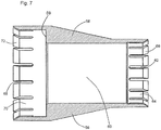
- the printing assembly preferably further comprises a clamping annulus which is referred to and identified by Reference Numerals 20a and 20oa, 20a representing an axial end of such annulus and 20oa representing an oppositely axial end of such annulus.
- An outer circumferential end or limit of the clamping annulus 20a,20oa is associated with Reference Numerals 22 and 26, such circumferential end 22,26 preferably being tiered or stepped so that the diameter of the axial end of the clamping annulus 20a is markedly greater than the diameter of the oppositely axial end of the clamping annulus 20oa.
- Such diameter differential is reflected at a tiered step or transition 24 between the two annulus portions. In a preferred embodiment, such diameter differential is between 2.54 cm and 5.08 cm (1" and 2").
- a radially inner periphery or limit of the clamping annulus 20a,20oa is denoted by Reference Numeral 28.
- the enlarged axial end of the clamping annulus 20a,20oa advantageously forms and defines a toroidal guide sleeve receiving space which may advantageously assist in insertions into and receipts of a clamp jaw supporting guide sleeve which is discussed further below.
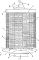
- the cylinder 1 preferably has a hollow bore 5 which is formed and defined by the cylinder's tiered inner wall 30,34.
- the diameter of the axial end of bore 5 defined by inner wall portion 30 is markedly greater than the corresponding oppositely axial diameter defined by inner wall 34, and a preferably 90° annular step or land 32 forms a transition between such inner wall tiers.
- Axial and oppositely axial compression rings 36 and 38 are preferably closely fitted to and are fixedly mounted upon inner wall tiers 30 and 34.
- the compression rings 36 and 38 are preferably mounted at axial and oppositely axial sides of a cross-sectional mid-line or midplane 37.
- Helically threaded mounting plate attachment sockets 40 are preferably presented at the oppositely axial end 18 of the cylinder 1.
- FIG. 5 the clamping annulus component 20a,20oa,22,24,26,28 is represented in the drawings.
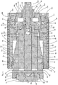
- the axle 74 which extends from a printing machine (not shown within views) may provide cantilevering support for and rotational drive to the cylinder 1.
- the axle 74 preferably includes or incorporates an oppositely axial clamp jaw ring 56, such ring preferably having a radially enlarged oppositely axial end 54 whose axial face 52 is annularly chamfered or beveled.
- the inside diameter of the clamp jaw ring 56 is preferably closely fitted to the outside diameter of an inwardly stepped oppositely axial end of axle 74, and the axial end of ring 56 preferably securely abuts axle step or land 76.
- clamp jaw ring 56 is securely held in place against land 76 by a retainer clip 78.
- a tiered clamping sleeve component of the printing assembly is referred to generally by Reference Arrow 58.
- the axial end of the tiered clamping sleeve 58 preferably presents an inwardly and annularly chamfered face 72, and the oppositely axial end of such sleeve preferably correspondingly presents an annular inwardly chamfered face 66.
- the axial and oppositely axial ends of the tiered clamping sleeve 58 preferably respectively present radially arrayed slots 68 and 62 which divide the chamfered faces 72 and 66 into radially arrayed pluralities of wedge clamping sections 70 and 64.
- the inside diameter of the bore 60 of sleeve 58 is preferably closely fitted for sliding receipt of axle 74, and the oppositely axial end of the bore 60 preferably presents an outward step or tier 59 for guide sleeve receipt and clearance as discussed below.
- chamfered faces 52 and 66 advantageously engage each other to radially outwardly deflect wedge sections 64 within the oppositely axial portion 20oa of the assembly's clamping annulus.
- annular and outwardly chamfered jaw face 42 is preferably provided, such face preferably being positioned for similarly angled engagements with chamfered axial face 72 of sleeve 58.
- an oppositely axial driving force may be translated to faces 52,56 while wedge sections 70 of sleeve 58 are substantially simultaneously radially outwardly deflected within the clamping annulus's axial end 20a.
- a ring configured guide sleeve 44 is preferably fixedly attached to or formed wholly with the axial jaw 42, such guide sleeve 44 preferably being closely fitted for sliding receipt over the axle 74 and within the annulus formed by sleeve step 59 and wedge sections 70.
- the oppositely axial end 46 of the guide sleeve 44 preferably terminates short of any interference with or impingement against sleeve step 59.
- means for oppositely axially driving jaw face 42 against the tiered clamping sleeve 58 in the manner described above are preferably provided, such means preferably comprising a jack screw assembly.
- Such assembly preferably comprises a bolt 100 having helical threads at its axial end.
- the bolt 100 is preferably rotatably supported at the oppositely axial end of the axle 74 by means of a bearing ring 90 whose axial end is fitted for receiving and bridging over axle end components, and fitted for abutting engagement of ring face 94 against the oppositely axial face of clamp jaw ring 56.
- a rotation stopping pin 82 is preferably provided for allowing axial installations and deinstallations of bearing ring 90 over the oppositely axial end of axle 74 while resisting rotation of that ring with respect to the axle 74.
- the axial end 96 of the bore 92 which rotatably receives bolt 100 is preferably enlarged for receipt of a coaxially mounted biasing spring 98 which, in operative engagement with clip 104, axially biases the bolt 100 for easing threaded engagements as discussed below.
- a tie bar 84 which is closely fitted for sliding axial movement within the channel 75 of axle 74 preferably presents an oppositely axially opening helically threaded socket 88.
- tie bar 84 Upon threaded engagement of the bolt 100 with said socket's threads and upon clockwise and right-handed turning of the bolt 100, tie bar 84 is advantageously pulled in the oppositely axial direction with respect to the axle 74.
- a "T” bar 85 preferably extends in the radial direction through a radially extending channel 86 within the axial end of the tie bar 84, and upon such oppositely axial drawing of tie bar 84, "T" bar 85 is simultaneously drawn oppositely axially.
- the assembly's axial jaw 42 preferably includes an annular rearward extension 39, such extension preferably forming and defining a "T" bar receiving channel 48.
- annular rearward extension 39 such extension preferably forming and defining a "T" bar receiving channel 48.
- the above described oppositely axial drawing force applied to the tie bar 84 further simultaneously drives jaw 42 against the axial end of the tiered clamping sleeve 58 for radially outwardly clamping deflections of, referring further simultaneously to Fig. 7 wedge clamping sections 64 and 70.
- a dirt and debris sealing "O" ring 50 is preferably interposed between the axle 74 and the axial extension 39 of clamp jaw 42.
- Fig. 5 the cylinder 1 of Fig. 1 is shown in Fig. 5 as installed over axle 74.
- the above described radially outward clamping deflections of the wedge sections 70 and 64 of the clamping sleeve 58 within the clamping annulus 20a,20oa advantageously drives those wedge sections 70 and 64 radially outwardly against the axial and oppositely axial compression rings 36 and 38.
- Such radially outward deflections of wedge sections 70 and 64 advantageously securely hold and position the cylinder 1 at a specifically desired location and orientation with respect to axle 74, such positioning provides for secure and accurate alignment of a magnetically attached ferro-magnetic printing plate 15.
- a cylinder end cap 104 is preferably fixedly and removably attached to the oppositely axial end of cylinder 1 by means of helically threaded bolts 41 which extend through bolt receiving apertures 103 within end cap 104, and which threadedly engage helically threaded sockets 40.
- a closely fitted spacer ring 106 having flange 108 and retainer clip 107 is interposed between end cap 104 and bearing member 90.
Landscapes
- Rolls And Other Rotary Bodies (AREA)
- Rotary Presses (AREA)
- Printing Plates And Materials Therefor (AREA)
Priority Applications (1)
| Application Number | Priority Date | Filing Date | Title |
|---|---|---|---|
| PL14826777T PL3022057T3 (pl) | 2013-07-18 | 2014-07-18 | Zespół drukujący |
Applications Claiming Priority (2)
| Application Number | Priority Date | Filing Date | Title |
|---|---|---|---|
| US13/945,726 US9162439B2 (en) | 2013-07-18 | 2013-07-18 | Printing assembly |
| PCT/US2014/047184 WO2015010013A2 (en) | 2013-07-18 | 2014-07-18 | Printing assembly |
Publications (3)
| Publication Number | Publication Date |
|---|---|
| EP3022057A2 EP3022057A2 (en) | 2016-05-25 |
| EP3022057A4 EP3022057A4 (en) | 2017-04-26 |
| EP3022057B1 true EP3022057B1 (en) | 2020-04-15 |
Family
ID=50146866
Family Applications (1)
| Application Number | Title | Priority Date | Filing Date |
|---|---|---|---|
| EP14826777.6A Active EP3022057B1 (en) | 2013-07-18 | 2014-07-18 | Printing assembly |
Country Status (4)
| Country | Link |
|---|---|
| US (2) | US9162439B2 (pl) |
| EP (1) | EP3022057B1 (pl) |
| PL (1) | PL3022057T3 (pl) |
| WO (1) | WO2015010013A2 (pl) |
Families Citing this family (2)
| Publication number | Priority date | Publication date | Assignee | Title |
|---|---|---|---|---|
| US10265989B2 (en) * | 2015-04-21 | 2019-04-23 | Think Laboratory Co. Ltd | Functional cylinder body and manufacturing method therefor |
| GB201915458D0 (en) | 2019-10-24 | 2019-12-11 | Sandon Global Engraving Tech Limited | Lightweight interchangeable magnetic sleeve and method of manufacture thereof |
Family Cites Families (13)
| Publication number | Priority date | Publication date | Assignee | Title |
|---|---|---|---|---|
| US1674635A (en) * | 1926-02-08 | 1928-06-26 | Paper & Textile Machinery Co | Expansion mandrel |
| US1958299A (en) * | 1930-10-15 | 1934-05-08 | Standard Process Corp | Intaglio printing methods and apparatus |
| US2987994A (en) * | 1958-08-18 | 1961-06-13 | Thomas K Allison | Mandrel and cylinder for gravure printing |
| US3590452A (en) * | 1969-01-09 | 1971-07-06 | Dayco Corp | Roller applicator device |
| US3739722A (en) * | 1971-08-13 | 1973-06-19 | Gross Instr Co | Print roll and mounting means |
| CH549474A (de) * | 1973-01-29 | 1974-05-31 | Buser Ag Maschf Fritz | Vorrichtung an rotationsfilmdruckmaschine zum loesbaren befestigen einer rundschablone. |
| US3919937A (en) * | 1974-03-15 | 1975-11-18 | Donnelley & Sons Co | Magnetic cylinder for printing presses |
| NL8003073A (nl) | 1980-05-28 | 1982-01-04 | Stork Screens Bv | Drukcilinder voorzien van een uitwendige bekleding, alsmede werkwijze en inrichting voor het bekleden van een cilinderoppervlak. |
| US4503769A (en) * | 1982-06-21 | 1985-03-12 | Armotek Industries, Inc. | Metal coated thin wall plastic printing cylinder for rotogravure printing |
| US6363850B1 (en) * | 1999-11-22 | 2002-04-02 | Mceachern David A. | Mounting printing plate cylinder having tapered bore to untapered rotatable drive shaft |
| DE50111987D1 (de) * | 2000-05-17 | 2007-03-22 | Eastman Kodak Co | Austauschbare Zylinderelemente an elektrographischen Druckeinheiten |
| DE10304117A1 (de) * | 2003-01-31 | 2004-08-05 | Giesecke & Devrient Gmbh | Spannzylinder zum Aufspannen zylindrischer Prägeformen für Prägewalzen |
| EP1555123A1 (de) * | 2004-01-17 | 2005-07-20 | Wilfried Jeurink | Druckvorrichtung |
-
2013
- 2013-07-18 US US13/945,726 patent/US9162439B2/en active Active
-
2014
- 2014-07-18 WO PCT/US2014/047184 patent/WO2015010013A2/en active Application Filing
- 2014-07-18 PL PL14826777T patent/PL3022057T3/pl unknown
- 2014-07-18 EP EP14826777.6A patent/EP3022057B1/en active Active
-
2015
- 2015-09-17 US US14/857,093 patent/US9308717B2/en active Active
Non-Patent Citations (1)
| Title |
|---|
| None * |
Also Published As
| Publication number | Publication date |
|---|---|
| WO2015010013A3 (en) | 2015-06-04 |
| EP3022057A4 (en) | 2017-04-26 |
| US9162439B2 (en) | 2015-10-20 |
| US9308717B2 (en) | 2016-04-12 |
| PL3022057T3 (pl) | 2020-11-02 |
| US20140053747A1 (en) | 2014-02-27 |
| EP3022057A2 (en) | 2016-05-25 |
| US20160001547A1 (en) | 2016-01-07 |
| WO2015010013A2 (en) | 2015-01-22 |
Similar Documents
| Publication | Publication Date | Title |
|---|---|---|
| EP2399673B1 (en) | Roller for high pressure roller grinder, roller grinder and method for assembling a roller for a roller grinder | |
| US10797549B2 (en) | Electric motor | |
| EP3022057B1 (en) | Printing assembly | |
| EP2892724B1 (en) | Assembly for axially aligning a print die | |
| CN103964238B (zh) | 分切机放卷固定装置及高速分切机 | |
| CN203114941U (zh) | 一种离合器及其中心套 | |
| CN104773558B (zh) | 一种布料卷绕筒安装机构 | |
| US8997322B1 (en) | Compact and portable hydraulic extracting and installing apparatus and associated method | |
| CN214945903U (zh) | 一体化多点制动重载电梯曳引机的制动器 | |
| CN205799367U (zh) | 一种拔轮器及其轮盘 | |
| CN210616372U (zh) | 一种多功能型简易式拆卸装置 | |
| CN201180072Y (zh) | 一种外转子式永磁同步无齿轮曳引机 | |
| JP4533905B2 (ja) | マルチパートスライドスリーブを備えた自動車両の摩擦クラッチ用クラッチリリース装置 | |
| CN101387318A (zh) | 轴-轮毂-连接装置的机械元件及该连接装置的制造方法 | |
| CN210770125U (zh) | 一种皮带轮 | |
| CN220770016U (zh) | 一种高强度轻量化制动凸轮轴 | |
| CN209737400U (zh) | 装载机驱动桥差速器固定装置 | |
| CN218743935U (zh) | 一种高效复合功能的滚压机用轧辊 | |
| CN210431169U (zh) | 一种适用于电机轴承免解体拆装的夹紧组件工装 | |
| CN210307620U (zh) | 轴承拆卸工具 | |
| CN202451748U (zh) | 夹紧式小皮带轮 | |
| CN209892639U (zh) | 一种转鼓中心轴 | |
| CN103935939B (zh) | 起重机车轮装配液压装置 | |
| CN206429493U (zh) | 一种快速安装型固定环 | |
| CN115263932A (zh) | 一种汽车轮毂用的圆锥滚子轴承 |
Legal Events
| Date | Code | Title | Description |
|---|---|---|---|
| PUAI | Public reference made under article 153(3) epc to a published international application that has entered the european phase |
Free format text: ORIGINAL CODE: 0009012 |
|
| 17P | Request for examination filed |
Effective date: 20160114 |
|
| AK | Designated contracting states |
Kind code of ref document: A2 Designated state(s): AL AT BE BG CH CY CZ DE DK EE ES FI FR GB GR HR HU IE IS IT LI LT LU LV MC MK MT NL NO PL PT RO RS SE SI SK SM TR |
|
| AX | Request for extension of the european patent |
Extension state: BA ME |
|
| DAX | Request for extension of the european patent (deleted) | ||
| A4 | Supplementary search report drawn up and despatched |
Effective date: 20170324 |
|
| RIC1 | Information provided on ipc code assigned before grant |
Ipc: B41F 27/02 20060101AFI20170320BHEP |
|
| REG | Reference to a national code |
Ref country code: DE Ref legal event code: R079 Ref document number: 602014063879 Country of ref document: DE Free format text: PREVIOUS MAIN CLASS: B41F0013200000 Ipc: B41F0027020000 |
|
| GRAP | Despatch of communication of intention to grant a patent |
Free format text: ORIGINAL CODE: EPIDOSNIGR1 |
|
| STAA | Information on the status of an ep patent application or granted ep patent |
Free format text: STATUS: GRANT OF PATENT IS INTENDED |
|
| RIC1 | Information provided on ipc code assigned before grant |
Ipc: B41F 27/02 20060101AFI20190502BHEP |
|
| INTG | Intention to grant announced |
Effective date: 20190605 |
|
| GRAJ | Information related to disapproval of communication of intention to grant by the applicant or resumption of examination proceedings by the epo deleted |
Free format text: ORIGINAL CODE: EPIDOSDIGR1 |
|
| STAA | Information on the status of an ep patent application or granted ep patent |
Free format text: STATUS: REQUEST FOR EXAMINATION WAS MADE |
|
| GRAP | Despatch of communication of intention to grant a patent |
Free format text: ORIGINAL CODE: EPIDOSNIGR1 |
|
| STAA | Information on the status of an ep patent application or granted ep patent |
Free format text: STATUS: GRANT OF PATENT IS INTENDED |
|
| INTC | Intention to grant announced (deleted) | ||
| INTG | Intention to grant announced |
Effective date: 20191030 |
|
| GRAS | Grant fee paid |
Free format text: ORIGINAL CODE: EPIDOSNIGR3 |
|
| GRAA | (expected) grant |
Free format text: ORIGINAL CODE: 0009210 |
|
| STAA | Information on the status of an ep patent application or granted ep patent |
Free format text: STATUS: THE PATENT HAS BEEN GRANTED |
|
| AK | Designated contracting states |
Kind code of ref document: B1 Designated state(s): AL AT BE BG CH CY CZ DE DK EE ES FI FR GB GR HR HU IE IS IT LI LT LU LV MC MK MT NL NO PL PT RO RS SE SI SK SM TR |
|
| REG | Reference to a national code |
Ref country code: CH Ref legal event code: EP |
|
| REG | Reference to a national code |
Ref country code: DE Ref legal event code: R096 Ref document number: 602014063879 Country of ref document: DE |
|
| REG | Reference to a national code |
Ref country code: IE Ref legal event code: FG4D |
|
| REG | Reference to a national code |
Ref country code: AT Ref legal event code: REF Ref document number: 1256791 Country of ref document: AT Kind code of ref document: T Effective date: 20200515 |
|
| REG | Reference to a national code |
Ref country code: NL Ref legal event code: MP Effective date: 20200415 |
|
| REG | Reference to a national code |
Ref country code: LT Ref legal event code: MG4D |
|
| PG25 | Lapsed in a contracting state [announced via postgrant information from national office to epo] |
Ref country code: SE Free format text: LAPSE BECAUSE OF FAILURE TO SUBMIT A TRANSLATION OF THE DESCRIPTION OR TO PAY THE FEE WITHIN THE PRESCRIBED TIME-LIMIT Effective date: 20200415 Ref country code: IS Free format text: LAPSE BECAUSE OF FAILURE TO SUBMIT A TRANSLATION OF THE DESCRIPTION OR TO PAY THE FEE WITHIN THE PRESCRIBED TIME-LIMIT Effective date: 20200815 Ref country code: NO Free format text: LAPSE BECAUSE OF FAILURE TO SUBMIT A TRANSLATION OF THE DESCRIPTION OR TO PAY THE FEE WITHIN THE PRESCRIBED TIME-LIMIT Effective date: 20200715 Ref country code: FI Free format text: LAPSE BECAUSE OF FAILURE TO SUBMIT A TRANSLATION OF THE DESCRIPTION OR TO PAY THE FEE WITHIN THE PRESCRIBED TIME-LIMIT Effective date: 20200415 Ref country code: GR Free format text: LAPSE BECAUSE OF FAILURE TO SUBMIT A TRANSLATION OF THE DESCRIPTION OR TO PAY THE FEE WITHIN THE PRESCRIBED TIME-LIMIT Effective date: 20200716 Ref country code: LT Free format text: LAPSE BECAUSE OF FAILURE TO SUBMIT A TRANSLATION OF THE DESCRIPTION OR TO PAY THE FEE WITHIN THE PRESCRIBED TIME-LIMIT Effective date: 20200415 Ref country code: NL Free format text: LAPSE BECAUSE OF FAILURE TO SUBMIT A TRANSLATION OF THE DESCRIPTION OR TO PAY THE FEE WITHIN THE PRESCRIBED TIME-LIMIT Effective date: 20200415 Ref country code: PT Free format text: LAPSE BECAUSE OF FAILURE TO SUBMIT A TRANSLATION OF THE DESCRIPTION OR TO PAY THE FEE WITHIN THE PRESCRIBED TIME-LIMIT Effective date: 20200817 |
|
| REG | Reference to a national code |
Ref country code: AT Ref legal event code: MK05 Ref document number: 1256791 Country of ref document: AT Kind code of ref document: T Effective date: 20200415 |
|
| PG25 | Lapsed in a contracting state [announced via postgrant information from national office to epo] |
Ref country code: HR Free format text: LAPSE BECAUSE OF FAILURE TO SUBMIT A TRANSLATION OF THE DESCRIPTION OR TO PAY THE FEE WITHIN THE PRESCRIBED TIME-LIMIT Effective date: 20200415 Ref country code: LV Free format text: LAPSE BECAUSE OF FAILURE TO SUBMIT A TRANSLATION OF THE DESCRIPTION OR TO PAY THE FEE WITHIN THE PRESCRIBED TIME-LIMIT Effective date: 20200415 Ref country code: RS Free format text: LAPSE BECAUSE OF FAILURE TO SUBMIT A TRANSLATION OF THE DESCRIPTION OR TO PAY THE FEE WITHIN THE PRESCRIBED TIME-LIMIT Effective date: 20200415 Ref country code: BG Free format text: LAPSE BECAUSE OF FAILURE TO SUBMIT A TRANSLATION OF THE DESCRIPTION OR TO PAY THE FEE WITHIN THE PRESCRIBED TIME-LIMIT Effective date: 20200715 |
|
| PG25 | Lapsed in a contracting state [announced via postgrant information from national office to epo] |
Ref country code: AL Free format text: LAPSE BECAUSE OF FAILURE TO SUBMIT A TRANSLATION OF THE DESCRIPTION OR TO PAY THE FEE WITHIN THE PRESCRIBED TIME-LIMIT Effective date: 20200415 |
|
| REG | Reference to a national code |
Ref country code: DE Ref legal event code: R097 Ref document number: 602014063879 Country of ref document: DE |
|
| PG25 | Lapsed in a contracting state [announced via postgrant information from national office to epo] |
Ref country code: IT Free format text: LAPSE BECAUSE OF FAILURE TO SUBMIT A TRANSLATION OF THE DESCRIPTION OR TO PAY THE FEE WITHIN THE PRESCRIBED TIME-LIMIT Effective date: 20200415 Ref country code: SM Free format text: LAPSE BECAUSE OF FAILURE TO SUBMIT A TRANSLATION OF THE DESCRIPTION OR TO PAY THE FEE WITHIN THE PRESCRIBED TIME-LIMIT Effective date: 20200415 Ref country code: ES Free format text: LAPSE BECAUSE OF FAILURE TO SUBMIT A TRANSLATION OF THE DESCRIPTION OR TO PAY THE FEE WITHIN THE PRESCRIBED TIME-LIMIT Effective date: 20200415 Ref country code: AT Free format text: LAPSE BECAUSE OF FAILURE TO SUBMIT A TRANSLATION OF THE DESCRIPTION OR TO PAY THE FEE WITHIN THE PRESCRIBED TIME-LIMIT Effective date: 20200415 Ref country code: DK Free format text: LAPSE BECAUSE OF FAILURE TO SUBMIT A TRANSLATION OF THE DESCRIPTION OR TO PAY THE FEE WITHIN THE PRESCRIBED TIME-LIMIT Effective date: 20200415 Ref country code: CZ Free format text: LAPSE BECAUSE OF FAILURE TO SUBMIT A TRANSLATION OF THE DESCRIPTION OR TO PAY THE FEE WITHIN THE PRESCRIBED TIME-LIMIT Effective date: 20200415 Ref country code: EE Free format text: LAPSE BECAUSE OF FAILURE TO SUBMIT A TRANSLATION OF THE DESCRIPTION OR TO PAY THE FEE WITHIN THE PRESCRIBED TIME-LIMIT Effective date: 20200415 Ref country code: RO Free format text: LAPSE BECAUSE OF FAILURE TO SUBMIT A TRANSLATION OF THE DESCRIPTION OR TO PAY THE FEE WITHIN THE PRESCRIBED TIME-LIMIT Effective date: 20200415 |
|
| PLBE | No opposition filed within time limit |
Free format text: ORIGINAL CODE: 0009261 |
|
| STAA | Information on the status of an ep patent application or granted ep patent |
Free format text: STATUS: NO OPPOSITION FILED WITHIN TIME LIMIT |
|
| PG25 | Lapsed in a contracting state [announced via postgrant information from national office to epo] |
Ref country code: SK Free format text: LAPSE BECAUSE OF FAILURE TO SUBMIT A TRANSLATION OF THE DESCRIPTION OR TO PAY THE FEE WITHIN THE PRESCRIBED TIME-LIMIT Effective date: 20200415 Ref country code: MC Free format text: LAPSE BECAUSE OF FAILURE TO SUBMIT A TRANSLATION OF THE DESCRIPTION OR TO PAY THE FEE WITHIN THE PRESCRIBED TIME-LIMIT Effective date: 20200415 |
|
| REG | Reference to a national code |
Ref country code: CH Ref legal event code: PL |
|
| 26N | No opposition filed |
Effective date: 20210118 |
|
| REG | Reference to a national code |
Ref country code: BE Ref legal event code: MM Effective date: 20200731 |
|
| PG25 | Lapsed in a contracting state [announced via postgrant information from national office to epo] |
Ref country code: LU Free format text: LAPSE BECAUSE OF NON-PAYMENT OF DUE FEES Effective date: 20200718 Ref country code: LI Free format text: LAPSE BECAUSE OF NON-PAYMENT OF DUE FEES Effective date: 20200731 Ref country code: CH Free format text: LAPSE BECAUSE OF NON-PAYMENT OF DUE FEES Effective date: 20200731 |
|
| PG25 | Lapsed in a contracting state [announced via postgrant information from national office to epo] |
Ref country code: BE Free format text: LAPSE BECAUSE OF NON-PAYMENT OF DUE FEES Effective date: 20200731 Ref country code: SI Free format text: LAPSE BECAUSE OF FAILURE TO SUBMIT A TRANSLATION OF THE DESCRIPTION OR TO PAY THE FEE WITHIN THE PRESCRIBED TIME-LIMIT Effective date: 20200415 |
|
| PG25 | Lapsed in a contracting state [announced via postgrant information from national office to epo] |
Ref country code: IE Free format text: LAPSE BECAUSE OF NON-PAYMENT OF DUE FEES Effective date: 20200718 |
|
| PG25 | Lapsed in a contracting state [announced via postgrant information from national office to epo] |
Ref country code: TR Free format text: LAPSE BECAUSE OF FAILURE TO SUBMIT A TRANSLATION OF THE DESCRIPTION OR TO PAY THE FEE WITHIN THE PRESCRIBED TIME-LIMIT Effective date: 20200415 Ref country code: MT Free format text: LAPSE BECAUSE OF FAILURE TO SUBMIT A TRANSLATION OF THE DESCRIPTION OR TO PAY THE FEE WITHIN THE PRESCRIBED TIME-LIMIT Effective date: 20200415 Ref country code: CY Free format text: LAPSE BECAUSE OF FAILURE TO SUBMIT A TRANSLATION OF THE DESCRIPTION OR TO PAY THE FEE WITHIN THE PRESCRIBED TIME-LIMIT Effective date: 20200415 |
|
| PG25 | Lapsed in a contracting state [announced via postgrant information from national office to epo] |
Ref country code: MK Free format text: LAPSE BECAUSE OF FAILURE TO SUBMIT A TRANSLATION OF THE DESCRIPTION OR TO PAY THE FEE WITHIN THE PRESCRIBED TIME-LIMIT Effective date: 20200415 |
|
| PGFP | Annual fee paid to national office [announced via postgrant information from national office to epo] |
Ref country code: GB Payment date: 20230713 Year of fee payment: 10 |
|
| PGFP | Annual fee paid to national office [announced via postgrant information from national office to epo] |
Ref country code: PL Payment date: 20230717 Year of fee payment: 10 Ref country code: FR Payment date: 20230724 Year of fee payment: 10 Ref country code: DE Payment date: 20230720 Year of fee payment: 10 |