US4503769A - Metal coated thin wall plastic printing cylinder for rotogravure printing - Google Patents
Metal coated thin wall plastic printing cylinder for rotogravure printing Download PDFInfo
- Publication number
- US4503769A US4503769A US06/390,379 US39037982A US4503769A US 4503769 A US4503769 A US 4503769A US 39037982 A US39037982 A US 39037982A US 4503769 A US4503769 A US 4503769A
- Authority
- US
- United States
- Prior art keywords
- cylinder
- sleeve
- rotogravure printing
- rotogravure
- layer
- Prior art date
- Legal status (The legal status is an assumption and is not a legal conclusion. Google has not performed a legal analysis and makes no representation as to the accuracy of the status listed.)
- Expired - Fee Related
Links
- 239000004033 plastic Substances 0.000 title claims abstract description 58
- 229920003023 plastic Polymers 0.000 title claims abstract description 58
- 229910052751 metal Inorganic materials 0.000 title claims abstract description 24
- 239000002184 metal Substances 0.000 title claims abstract description 24
- RYGMFSIKBFXOCR-UHFFFAOYSA-N Copper Chemical compound [Cu] RYGMFSIKBFXOCR-UHFFFAOYSA-N 0.000 claims abstract description 56
- 229910052802 copper Inorganic materials 0.000 claims abstract description 56
- 239000010949 copper Substances 0.000 claims abstract description 56
- HCHKCACWOHOZIP-UHFFFAOYSA-N Zinc Chemical compound [Zn] HCHKCACWOHOZIP-UHFFFAOYSA-N 0.000 claims description 24
- 229910052725 zinc Inorganic materials 0.000 claims description 24
- 239000011701 zinc Substances 0.000 claims description 24
- 239000011248 coating agent Substances 0.000 claims description 13
- 238000000576 coating method Methods 0.000 claims description 13
- 238000000034 method Methods 0.000 claims description 10
- 239000000835 fiber Substances 0.000 claims description 6
- 230000008569 process Effects 0.000 claims description 6
- 238000009713 electroplating Methods 0.000 claims description 5
- 230000006872 improvement Effects 0.000 claims description 5
- 239000000758 substrate Substances 0.000 claims description 5
- 238000007750 plasma spraying Methods 0.000 claims description 3
- UONOETXJSWQNOL-UHFFFAOYSA-N tungsten carbide Chemical compound [W+]#[C-] UONOETXJSWQNOL-UHFFFAOYSA-N 0.000 claims description 3
- KXGFMDJXCMQABM-UHFFFAOYSA-N 2-methoxy-6-methylphenol Chemical compound [CH]OC1=CC=CC([CH])=C1O KXGFMDJXCMQABM-UHFFFAOYSA-N 0.000 claims description 2
- 239000004698 Polyethylene Substances 0.000 claims description 2
- 229920001568 phenolic resin Polymers 0.000 claims description 2
- 239000005011 phenolic resin Substances 0.000 claims description 2
- -1 polyethylene Polymers 0.000 claims description 2
- 229920000573 polyethylene Polymers 0.000 claims description 2
- 238000010285 flame spraying Methods 0.000 claims 1
- 238000005507 spraying Methods 0.000 claims 1
- 238000004519 manufacturing process Methods 0.000 abstract description 2
- 229910000831 Steel Inorganic materials 0.000 description 7
- 239000010959 steel Substances 0.000 description 7
- 230000008901 benefit Effects 0.000 description 5
- 239000007921 spray Substances 0.000 description 5
- XEEYBQQBJWHFJM-UHFFFAOYSA-N Iron Chemical compound [Fe] XEEYBQQBJWHFJM-UHFFFAOYSA-N 0.000 description 4
- 230000008859 change Effects 0.000 description 3
- 239000002245 particle Substances 0.000 description 3
- 238000003860 storage Methods 0.000 description 3
- VYZAMTAEIAYCRO-UHFFFAOYSA-N Chromium Chemical compound [Cr] VYZAMTAEIAYCRO-UHFFFAOYSA-N 0.000 description 2
- 238000005275 alloying Methods 0.000 description 2
- 230000015572 biosynthetic process Effects 0.000 description 2
- 229910052804 chromium Inorganic materials 0.000 description 2
- 239000011651 chromium Substances 0.000 description 2
- 238000010276 construction Methods 0.000 description 2
- 239000013078 crystal Substances 0.000 description 2
- 238000005530 etching Methods 0.000 description 2
- 229910052742 iron Inorganic materials 0.000 description 2
- 230000002787 reinforcement Effects 0.000 description 2
- 238000000926 separation method Methods 0.000 description 2
- 229910052709 silver Inorganic materials 0.000 description 2
- 239000004332 silver Substances 0.000 description 2
- 229920002430 Fibre-reinforced plastic Polymers 0.000 description 1
- 239000010953 base metal Substances 0.000 description 1
- 230000015556 catabolic process Effects 0.000 description 1
- 238000011109 contamination Methods 0.000 description 1
- 230000008602 contraction Effects 0.000 description 1
- 238000006731 degradation reaction Methods 0.000 description 1
- 230000000593 degrading effect Effects 0.000 description 1
- 230000001419 dependent effect Effects 0.000 description 1
- 238000009792 diffusion process Methods 0.000 description 1
- 238000004070 electrodeposition Methods 0.000 description 1
- 239000004744 fabric Substances 0.000 description 1
- 239000011151 fibre-reinforced plastic Substances 0.000 description 1
- 239000003365 glass fiber Substances 0.000 description 1
- 238000009434 installation Methods 0.000 description 1
- 230000003993 interaction Effects 0.000 description 1
- 239000000463 material Substances 0.000 description 1
- 230000007246 mechanism Effects 0.000 description 1
- 239000005022 packaging material Substances 0.000 description 1
- 238000004806 packaging method and process Methods 0.000 description 1
- 229920000728 polyester Polymers 0.000 description 1
- 238000005488 sandblasting Methods 0.000 description 1
Images


Classifications
-
- B—PERFORMING OPERATIONS; TRANSPORTING
- B41—PRINTING; LINING MACHINES; TYPEWRITERS; STAMPS
- B41F—PRINTING MACHINES OR PRESSES
- B41F27/00—Devices for attaching printing elements or formes to supports
- B41F27/10—Devices for attaching printing elements or formes to supports for attaching non-deformable curved printing formes to forme cylinders
- B41F27/105—Devices for attaching printing elements or formes to supports for attaching non-deformable curved printing formes to forme cylinders for attaching cylindrical printing formes
-
- Y—GENERAL TAGGING OF NEW TECHNOLOGICAL DEVELOPMENTS; GENERAL TAGGING OF CROSS-SECTIONAL TECHNOLOGIES SPANNING OVER SEVERAL SECTIONS OF THE IPC; TECHNICAL SUBJECTS COVERED BY FORMER USPC CROSS-REFERENCE ART COLLECTIONS [XRACs] AND DIGESTS
- Y10—TECHNICAL SUBJECTS COVERED BY FORMER USPC
- Y10T—TECHNICAL SUBJECTS COVERED BY FORMER US CLASSIFICATION
- Y10T428/00—Stock material or miscellaneous articles
- Y10T428/12—All metal or with adjacent metals
- Y10T428/12493—Composite; i.e., plural, adjacent, spatially distinct metal components [e.g., layers, joint, etc.]
- Y10T428/12771—Transition metal-base component
- Y10T428/12861—Group VIII or IB metal-base component
- Y10T428/12903—Cu-base component
- Y10T428/1291—Next to Co-, Cu-, or Ni-base component
Definitions
- the present invention relates to the formation of a metal coated thin wall plastic printing cylinder for flexographic and rotogravure printing.
- copper is the preferred metal for the external surface of the printing plate or roll to receive the printing image.
- the coating of copper onto a base metal is relatively straightforward but the coating of copper onto a non-conductive substrate can be difficult.
- U.S. Pat. No. 3,483,074 discloses a printing plate which is made of a filled polyethylene coated with silver and then copper. However, silver is quite expensive so this method is not commercially feasible.
- the mode of application of copper is often important in determining the ultimate utility of the printing base and particularly for use in rotogravure printing cylinders.
- Rotogravure printing cylinders contain an etched metal (generally copper) surface which is the desired printed image.
- metal coated plastic based printing cylinders One of the difficulties with metal coated plastic based printing cylinders has been the ability to plate copper onto the plastic cylinders. While such a coating has occasionally been done, it has been found that in use, the copper layer tends to separate and/or blister and ultimately separate from the plastic cylinder.
- Rotogravure printing is known to be a high quality process used for the production of wallpaper, packaging materials, floor covering, tag and label and other, more or less continuously printed patterns which can be run in relatively long runs. The rotogravure printing cylinder prints on a complete 360 degree circumference.
- a lightweight plastic based rotogravure printing roll is its ability to be handled and stored as compared to conventional copper plated, steel printing cylinders. It would be particularly useful to have a plastic-based printing cylinder that could be replaced by a similar plastic-based printing cylinder having the same or a different printing image without having to take apart the printing press and particularly without having to take apart at least one of the journal portions of the printing press since, in that fashion, alignment of the new metal coated plastic-based cylinder could be made substantially quicker. In the installation of a conventional copper-coated steel rotogravure cylinder today, alignment can take several hours.
- a rotogravure printing cylinder combination comprising at least one etchable thin walled, plural metal coated hollow plastic cylinder sleeve, means within said hollow plastic cylinder sleeve sufficient to provide support for said cylinder during printing; and journal means disposed at the ends of the cylinder sleeve to provide support for said cylinder in a rotogravure printing machine.
- a rotogravure printing press including at least one rotogravure roll or cylinder and at least one impression roll, the improvement which comprises using the above-described rotogravure printing cylinder as the rotogravure cylinder.
- a rotogravure printing cylinder sleeve comprising a thin walled hollow plastic cylinder having a first zinc layer mechanically interlocked thereon, a first copper layer and a second copper layer of the same or greater hardness than the said first layer, said second copper layer being capable of being etched.
- Also provided is a process for forming a sleeve adapted for use in rotogravure printing which comprises providing a thin wall plastic cylinder, distorting the surface thereof to provide means to interlock a subsequent zinc coating onto the plastic, applying a zinc coating which is mechanically interlocked with the plastic substrate, plasma spraying a thin layer of copper onto the zinc layer and electroplating a further layer of copper onto the sprayed copper layer.
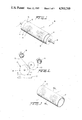
- FIG. 1 is a perspective showing a finished rotogravure roll of the present invention
- FIG. 2 is a representation of a rotogravure printing process
- FIG. 3 is a perspective of a thin-walled metal coated, plastic cylinder
- FIG. 4 is a cross section through FIG. 1 at line A--A;
- FIG. 5 is a view in exploded view of a mandrel upon which the cylinder of FIG. 3 may be used;
- FIG. 6 is a partial cross-sectional view of a portion of a rotogravure printing press useful in the present invention.
- the rotogravure printing cylinder of the present invention is indicated generally as 10 in FIG. 1.
- the cylinder includes a thin-walled metal coated plastic cylindrical sleeve 11 (the details of which are set forth hereinbelow) which contains an etched surface 12 which contains the desired printing image (not shown).
- the outer portions 13 and 14 of the surface 12 are unetched and, as explained below, may be advantageously used to expedite registry of the rotogravure printing cylinders when they are being changed.
- the cylinder 11 is disposed between two end portions 15 and 16. Journal bearings 17 and 18 are provided at the end portions 15 and 16, respectively, to provide for support and driving force of the cylinder within a conventional rotogravure printing press (not shown).
- FIG. 2 shows a general representation of the principle involved. That is, the rotogravure printing cylinder 20 containing the etched printing image is partially immersed in a reservoir 22 of ink which is picked up by the etched areas (not shown). A doctor blade removes excess ink and returns same to the ink reservoir 22. A substrate 23 (paper, cloth or the like) is fed from a supply roll 24 between the rotogravure printing cylinder 20 and impression roller 24 which maintains a fixed pressure on the rotogravure cylinder to properly transfer the desired image. The printed substrate 25 is then wound on a take-up roll 26 or other passed to further handling in a conventional manner.
- a take-up roll 26 or other passed to further handling in a conventional manner.
- the thin-walled, metal coated cylindrical sleeve 11 is shown generally in FIG. 3 and in an expanded partial cross-sectional view in FIG. 4.
- the rotogravure printing cylinder of the present invention includes a number of layers applied in specific manner.
- a hollow cylinder of a phenolic resin or polyester containing fiber reinforcements 29 (e.g., glass fiber) which are added for reinforcement and dimensional stability is molded on a mandrel to provide the thin walled plastic cylinder 30 having a specific, close tolerance internal diameter and a particular thickness which generally will be in the range of about 1/8 of an inch, although the latter can be adjusted for different mandrel sizes to a thickness of from about 1/16 to 1/4 inch).
- the fiber filled plastic core is then treated to texture or distort the surface to produce a "cavernous" surface (indicated generally as 31 in FIG. 4) for a better interlocking of a zinc layer which is thereafter applied. While this can be done by various means, it is preferred that it be done mechanically by sand blasting the plastic surface.
- a thin, e.g., 10-40, generally about 15 to 25, mils thickness (one mil being one-thousandth of an inch) zinc coating 32 is applied to the textured plastic core 30 by conventional flame spray metallizing wire gun at about 300° F. to provide a zinc coat which is mechanically interlocked with the fiber reinforced plastic core by filling in the textured surface previously produced. While the temperature of the flame spray at the gun is about 300° F., the temperature of the deposited zinc particles is believed to be significantly less and particularly to be below the stability temperature limit of the fiber filled plastic base (that is, below about 220° to 240° F.).
- a first copper layer 33 is also sprayed by plasma spray onto the zinc surface 32 to produce a copper layer of approximately 10-40, generally from about 15 to 25, mils thickness. It has been found that the copper particles applied by the plasma spray penetrate the zinc surface providing not only a mechanically interlocking but also some alloying in a diffusion zone 34 adjacent the interface between the copper layer 33 and the zinc layer 32. It is believed that the adherence between the two layers is more dependent on the interlocking (and therefore the velocity of the particle) than on any metallurgical alloying.
- the application of this particular layer by plasma spraying is also advantageous since copper layers are often formed by electrocoating which can cause surface contamination or a particular copper crystalline lattice formation which weakens the surface or causes spots.
- the application of the flame sprayed copper layer 33 onto the zinc coated, fiber-filled plastic core produces a basic gravure core which may be useful in some instances after etching or engraving.
- a further layer 35 of electrolytic copper in the range of 4 to 10, preferably 5 to 6, mils is then electrolytically deposited in a conventional fashion onto this basic gravure core.
- the hardness of the electrolytic copper can be substantially higher, (in the range Vickers hardness of 105 up to 200) than that of the flame sprayed copper (Vickers hardness of 105).
- the prior application of the sprayed zinc and copper layers 32 and 33 facilitates the electroplating application of copper layer 35 since they are present in an amount sufficient to effectively convert the sleeve into a conductive body (as opposed to a non-conductive plastic body).
- This coated core is then polished and engraved in the same manner as a normal rotogravure cylinder.
- Any engraving process can be used.
- the roll can be engraved by mechanical engraving, mechanical-electrical engraving or photo-engraving.
- This engraved sleeve can be used in publication printing but generally not in other areas, (for example packaging, tag and label, wall cover, floor covering).
- a hard surface coating 36 of chromium or tungsten carbide of about 2 to 8 mils thickness can thereafter be applied.
- the tungsten carbide is applied by the process of plasma flame spray as shown in my U.S. Pat. No. 4,262,034.
- the chromium, if used, is normally put on by electroplating.
- the sleeve 11 can be formed so that the etching or engraving leaves an unetched or unengraved portion 13 and 14 at each end of the sleeve 11. In this manner, the printing image will be always placed in the same relative lateral position in the printing press. In this manner, it is relatively easy to change sleeves and/or cylinders and still maintain the proper lateral alignment of the engraved printing image.
- register mark 40 Also shown on the sleeve 11 is a register mark 40.
- a similar register mark 41 appears on the end portion 15 so that the sleeve can also be readily aligned up when replacing sleeves on the supporting structure.
- this also makes the alignment of the rotogravure printing cylinder in the printing press considerably easier and faster than that obtainable when changing an entire conventional printed roll and thus offers significant advantages both in cost and time savings to the ultimate user.
- a small tab 77 (See FIG. 6) can be formed on the end portion 15 with a corresponding groove 78 in the cylinder to facilitate alignment.
- the sleeve 11 as previously described can be used in any printing operation in which it may be supportably aligned in a printing press and used for printing.
- a suitable mechanism to support and hold the sleeve in place and form the cylinder 10 is shown in FIG. 5.
- a rod generally indicated as 50 having a first (or register) end 15 with journal bearing 17 adapted to be placed into a printing press.
- the end portion 15 contains the register mark 41 which corresponds to the register mark 40 on the sleeve 11 (not shown).
- the rod has a first tapered portion 51, an intermediate flat portion 52 and a second tapered portion 53 also tapered in the same direction as tapered portion 51. Beyond the tapered portion 53, the rod has a flat threaded portion 54 and ends in the journal bearing 18.
- a sleeve portion generally indicated as 60.
- This sleeve portion 60 is adapted to receive the cylinder 11 (shown in dotted lines) such that the cylinder 11 abuts the flange of end portion 15.
- the outer diameter of the sleeve 60 is slightly less in the unassembled position (assembly described below) than the inner diameter of the metal coated plastic cylinder 11 and of end portion 16.
- the sleeve portion 60 has an internal taper portion 61, an intermediate flat portion 62 and a second taper portion 63 which correspond to the first taper 51, intermediate flat portion 52 and second taper portion 53 of the rod portion 50.
- the outer portion of the sleeve 60 is formed into segmented fingers 64 and are joined by a split ring 65 to the rotable end portion 16 which is internally threaded to correspond to the threaded shank 54 of the rod portion 50.
- a sleeve 11 such as shown in FIG. 3 is placed about the sleeve portion 60.
- the sleeve 11 and sleeve portion 60 are the same length.
- the sleeve 11-sleeve portion 60 assembly is then placed over the rod portion 50 and tightened by screwing the threaded shank 54 into the hole threaded 66.
- the interaction of the two tapered portion 51 and 53 on the rod with the tapered portions 61 and 63 on the inside of the tube cause a slight expansion of the segmented fingers 64, into tight contact with and along essentially all of the inside diameter of the sleeve 11 thus firmly locking the sleeve in place and forming the rotogravure cylinder 10.
- assembly 10 is designed to be placed within a printing machine with one end (that is, the end having end portion 16) being releasable to permit contraction of the segmented fingers 64 and removal of sleeve 11 without removing the journals and supporting structure from the machine.
- one end that is, the end having end portion 16
- the cylinder 11 with its printing image may be quickly and easily removed from a printing press and a new cylindrical sleeve (with the same or new printing image) quickly and easily assembled thereon.
- this may be accomplished by supporting journal 17 through press bearing 70 (housing therefor not shown but fixed in place) and cylinder drive gear 71 in a cantilever support bearing 72 which is disposed in a support housing 73 attached to the press side frame 74.
- press bearing 70 housing therefor not shown but fixed in place
- cylinder drive gear 71 in a cantilever support bearing 72 which is disposed in a support housing 73 attached to the press side frame 74.
- the cantilever support bearing 72 does not contact the support housing 73.
- the cylinder 10 (the parts of which shown being identified by the same numerals as in the other Figures) is supported at the other journal end 18 by a bearing 75 which is fitted onto journal 18 and remains in place thereon.
- Bearing 75 is supported by retractable bearing housing 76 which is pneumatically or hydraulically operable (not shown) to a running (or normal operating) position shown in solid lines and a retractable position shown in dotted lines.
- Bearing 75 has an outer diameter less than the inner diameter of sleeve 11 and the press side frame 79 in this instance is of a height to expose at least the diameter of the cylinder 10.
- the retractable journal bearing support 75 is retracted to the dotted line position, the assembly is released by unscrewing rotatable end portion 16 to release the expanded finger segments 64 thus releasing the cylinder sleeve 11 which can then be removed from the sleeve portion 60 over the end portion 16 and bearing 74.
- a new cylinder sleeve can be placed on the sleeve in the same fashion and the assembly then tightened by rotating end portion 16.
- the register marks 41 on the end portion and 40 on the cylinder can be aligned (or the tab 77 inserted into groove 78) and the printing distances 13 and 14 will be automatically aligned because the cylinder is always etched or engraved at that distance and each cylinder is always placed in the same position (that is, abutting the end portion 15).
- the rotogravure cylinder of the present invention offers a substantial opportunity for rapid change of rotogravure printing images.
- the particular mode of construction of the present invention is very advantageous in that the initial layer of zinc (which is applied quickly and at a relatively low temperature to avoid degradation of the plastic core) prevents the copper, which is applied at a much higher temperature, from degrading the plastic surface. It has been found that the copper cannot be applied directly onto the plastic without causing potential separation problems.
- the sprayed copper layer has a density which helps to obtain the proper quality of the electroplated copper layer which needs to be of high quality since it is the layer which is photoengraved. In reuse of the cylinders, only the electrolytic copper layer or a portion thereof is generally removed because the engraved image layer is generally only about 3 mils thick and a new electrolytic copper layer may be applied, if necessary.
- the lightweight nature of the rotographic cylinder of the present invention eliminates mechanic time and damage which can often be done during a cylinder change and simplifies storage problems for rotogravure printers who may have as many as 2,000 or more rolls in storage. Since the rolls generally used today are copper coated steel cylinders, it will be apparent that the use of a thin walled, metal coated plastic cylinder of the present invention offers significantly improved advantages.
- the sleeve of the present invention is in and of itself incapable of use in a rotogravure printing machine without an internal support structure because of the possibility of flexing under the pressures used.
- a suitable supporting structure must be provided.
- the sleeves themselves offer significant advantages and may be used with any such suitable support.
- more than one sleeve 11 can be used in any given assembly. That is, two or more can be applied across the length of the rod portion and any one of which may be changed at any given time in accordance with the above procedures.
Abstract
Description
Claims (17)
Priority Applications (1)
| Application Number | Priority Date | Filing Date | Title |
|---|---|---|---|
| US06/390,379 US4503769A (en) | 1982-06-21 | 1982-06-21 | Metal coated thin wall plastic printing cylinder for rotogravure printing |
Applications Claiming Priority (1)
| Application Number | Priority Date | Filing Date | Title |
|---|---|---|---|
| US06/390,379 US4503769A (en) | 1982-06-21 | 1982-06-21 | Metal coated thin wall plastic printing cylinder for rotogravure printing |
Publications (1)
| Publication Number | Publication Date |
|---|---|
| US4503769A true US4503769A (en) | 1985-03-12 |
Family
ID=23542240
Family Applications (1)
| Application Number | Title | Priority Date | Filing Date |
|---|---|---|---|
| US06/390,379 Expired - Fee Related US4503769A (en) | 1982-06-21 | 1982-06-21 | Metal coated thin wall plastic printing cylinder for rotogravure printing |
Country Status (1)
| Country | Link |
|---|---|
| US (1) | US4503769A (en) |
Cited By (53)
| Publication number | Priority date | Publication date | Assignee | Title |
|---|---|---|---|---|
| WO1987003843A1 (en) * | 1985-12-20 | 1987-07-02 | Jens Erik Sattrup | A method of producing a surface sleeve for a plate cylinder for printing purposes |
| US4841857A (en) * | 1986-03-03 | 1989-06-27 | Nissha Printing Co., Ltd. | Thin-film forming apparatus |
| US4860652A (en) * | 1986-05-24 | 1989-08-29 | Kabushikigaisha Tokyo Kikai Seisakusho | Mesh roller for planography |
| US4879791A (en) * | 1987-12-24 | 1989-11-14 | Albert-Frankenthal Ag | Method of producing a pitted roll for an offset litho printing press |
| US4912824A (en) * | 1989-03-14 | 1990-04-03 | Inta-Roto Gravure, Inc. | Engraved micro-ceramic-coated cylinder and coating process therefor |
| EP0366395A2 (en) * | 1988-10-24 | 1990-05-02 | Lavalley Industries Inc | Printing sleeves and methods for mounting and dismounting such printing sleeves |
| US5023985A (en) * | 1989-02-28 | 1991-06-18 | Valmet Paper Machinery Inc. | Coated roll for a paper making machine |
| AU622809B2 (en) * | 1989-02-23 | 1992-04-16 | Erminio Rossini S.P.A. | Method for producing plastics cylinders for printing in general, in particular for rotogravure and flexography, and the cylinder obtained |
| US5216954A (en) * | 1991-10-24 | 1993-06-08 | Thompson William L | Multi-section mountable sleeves and methods for mounting and dismounting same |
| US5356506A (en) * | 1992-06-12 | 1994-10-18 | The Procter & Gamble Company | Modular construction pattern rolls for use in paper converting |
| EP0623466A2 (en) * | 1993-04-19 | 1994-11-09 | Hoechst Aktiengesellschaft | Printing roller with a sleeve of hot, wound fibre-reinforced, thermoplastic material and a plasma-sprayed copper, or copper alloy coating |
| WO1994026534A1 (en) * | 1993-05-12 | 1994-11-24 | Hoechst Aktiengesellschaft | Process for producing print rolls made of a metallic core cylinder and a plasma-sprayed copper or copper alloy coating |
| US5511476A (en) * | 1993-10-26 | 1996-04-30 | R. R. Donnelley & Sons Co. | Magnetic cylinder with surface gripping |
| EP0732201A1 (en) * | 1995-03-14 | 1996-09-18 | Erminio Rossini S.P.A. | Concentric double sleeve for a rotary printing cylinder |
| US5583647A (en) * | 1993-05-05 | 1996-12-10 | Ohio Electronic Engravers, Inc. | Cylinder support apparatus and method for use in an engraver |
| US5735206A (en) * | 1995-03-20 | 1998-04-07 | Erminio Rossini, Spa | Deformable mandrels for rotary printing cylinders |
| US5791245A (en) * | 1995-05-05 | 1998-08-11 | De Pretto-Escher Wyss S.R.L. | Pressure roll |
| US5819657A (en) * | 1996-03-11 | 1998-10-13 | Ermino Rossini, Spa | Air carrier spacer sleeve for a printing cylinder |
| US5840386A (en) * | 1996-02-22 | 1998-11-24 | Praxair S.T. Technology, Inc. | Sleeve for a liquid transfer roll and method for producing it |
| US5925231A (en) * | 1996-11-22 | 1999-07-20 | Metzger; Hubert F. | Method for electroplating rotogravure cylinder using ultrasonic energy |
| US5967046A (en) * | 1996-05-03 | 1999-10-19 | Heidelberger Druckmaschinen Ag | Printing machine cylinder with an anti-corrosion protective layer, and method for producing such a cylinder |
| US6173496B1 (en) | 1996-10-16 | 2001-01-16 | Fort James Corporation | Embossing system including sleeved rolls |
| US6197169B1 (en) | 1996-11-22 | 2001-03-06 | Hubert F. Metzger | Apparatus and method for electroplating rotogravure cylinder using ultrasonic energy |
| US6231728B1 (en) | 1996-11-22 | 2001-05-15 | Hubert F. Metzger | Electroplating apparatus |
| US20020038789A1 (en) * | 1998-01-29 | 2002-04-04 | Grear Philip Joseph | Device for producing material having optically varying effects and method of producing the same |
| US6393249B1 (en) | 2000-10-04 | 2002-05-21 | Nexpress Solutions Llc | Sleeved rollers for use in a fusing station employing an internally heated fuser roller |
| US6393226B1 (en) * | 2000-10-04 | 2002-05-21 | Nexpress Solutions Llc | Intermediate transfer member having a stiffening layer and method of using |
| US20020060518A1 (en) * | 2000-11-17 | 2002-05-23 | Koninklijke Philips Electronics N.V. | Organic electroluminescent device and a method of manufacturing thereof |
| US6541171B1 (en) | 2000-10-04 | 2003-04-01 | Nexpress Solutions Llc | Sleeved photoconductive member and method of making |
| US6547936B1 (en) | 1996-11-22 | 2003-04-15 | Chema Technology, Inc. | Electroplating apparatus having a non-dissolvable anode |
| ES2187236A1 (en) * | 2000-05-22 | 2003-05-16 | Comexi Sa | Improvements in the carrying cliches rollers for graphic expansion machines. |
| US6567641B1 (en) | 2000-10-04 | 2003-05-20 | Nexpress Solutions Llc | Sleeved rollers for use in a fusing station employing an externally heated fuser roller |
| US6684783B2 (en) | 2001-08-17 | 2004-02-03 | Creo Inc. | Method for imaging a media sleeve on a computer-to-plate imaging machine |
| US6703095B2 (en) | 2002-02-19 | 2004-03-09 | Day International, Inc. | Thin-walled reinforced sleeve with integral compressible layer |
| US20050000814A1 (en) * | 1996-11-22 | 2005-01-06 | Metzger Hubert F. | Electroplating apparatus |
| WO2005012589A1 (en) * | 2003-08-01 | 2005-02-10 | Praxair S. T. Technology, Inc. | Method of thermal spraying metal |
| EP1543962A1 (en) * | 2003-12-19 | 2005-06-22 | FISCHER & KRECKE GMBH & CO. | Gravure cylinder |
| US20050150406A1 (en) * | 2004-01-09 | 2005-07-14 | Kanga Rustom S. | Printing sleeve with an intergrated printing surface |
| US6929723B2 (en) | 1996-11-22 | 2005-08-16 | Hubert F. Metzger | Electroplating apparatus using a non-dissolvable anode and ultrasonic energy |
| US20050217522A1 (en) * | 2004-03-24 | 2005-10-06 | Man Roland Druckmaschine Ag | Rolls and cylinders with a steel core for offset presses |
| US20050233880A1 (en) * | 2004-04-15 | 2005-10-20 | Schafer Composites Gmbh | Roll and method for the manufacture of such a roll |
| US20060210928A1 (en) * | 2004-11-12 | 2006-09-21 | Macdermid Printing Solutions, Llc | Method for thermally processing photosensitive printing sleeves |
| US20070089625A1 (en) * | 2005-10-20 | 2007-04-26 | Elbit Vision Systems Ltd. | Method and system for detecting defects during the fabrication of a printing cylinder |
| US20070160934A1 (en) * | 2004-01-30 | 2007-07-12 | Macdermid Printing Solutions, Llc | Photosensitive printing sleeves and method of forming the same |
| US20070182049A1 (en) * | 2002-07-22 | 2007-08-09 | Toyota Motor Sales, U.S.A. Inc. | Vibration apparatus and methods of vibration |
| US20090023567A1 (en) * | 2005-02-24 | 2009-01-22 | Gerhard Johner | Coated Member, Especially Roller, Made of Carbon Fiber-Reinforced Plastic (CFK) for Paper Machines and Printing Presses, and Method for the Production of such a Member |
| US20100170801A1 (en) * | 1999-06-30 | 2010-07-08 | Chema Technology, Inc. | Electroplating apparatus |
| US20140053747A1 (en) * | 2013-07-18 | 2014-02-27 | George Pantchev | Printing Assembly |
| US20170087818A1 (en) * | 2013-01-08 | 2017-03-30 | Paramount International Services Ltd. | Rotogravure cylinders, products and use thereof |
| WO2017089221A1 (en) | 2015-11-26 | 2017-06-01 | Sandon Global Engraving Technology Ltd | A sleeve for a bridge mandrel, and a bridge mandrel and sleeve assembly |
| US20180039207A1 (en) * | 2015-04-24 | 2018-02-08 | Hp Indigo B.V. | Release layer |
| CN112941607A (en) * | 2019-12-11 | 2021-06-11 | Sk纳力世有限公司 | Cathode assembly for electroplating equipment |
| WO2023072896A1 (en) | 2021-11-01 | 2023-05-04 | Sandon Global Engraving Technology Limited | An end ring for a sleeve, a sleeve adapted to receive such an end ring, and a sleeve assembly incorporating such an end ring |
Citations (25)
| Publication number | Priority date | Publication date | Assignee | Title |
|---|---|---|---|---|
| US662852A (en) * | 1899-11-01 | 1900-11-27 | Edward Hett | Method of producing surfaces for printing, &c. |
| US748004A (en) * | 1900-01-27 | 1903-12-29 | American Lithographic Co | Printing-form. |
| US972906A (en) * | 1904-12-03 | 1910-10-18 | American Lithographic Co | Form-support for printing-presses. |
| US1319107A (en) * | 1919-10-21 | Cylindrical printing-plate | ||
| US1674635A (en) * | 1926-02-08 | 1928-06-26 | Paper & Textile Machinery Co | Expansion mandrel |
| US1809466A (en) * | 1927-12-08 | 1931-06-09 | Johannisberg Gmbh Maschf | Intaglio printing machine |
| US1958299A (en) * | 1930-10-15 | 1934-05-08 | Standard Process Corp | Intaglio printing methods and apparatus |
| GB514632A (en) * | 1938-05-11 | 1939-11-14 | Joseph Foster | Improvements in and relating to means for the production of patterns by printing or embossing |
| US2294879A (en) * | 1939-04-24 | 1942-09-08 | Harry F Affelder | Plate mounting |
| US2429752A (en) * | 1946-02-20 | 1947-10-28 | William E Platt | Abrading tool |
| DE748422C (en) * | 1941-01-19 | 1951-08-23 | Antonius Kufferath | Form roller for paper machines |
| US2776256A (en) * | 1953-03-19 | 1957-01-01 | Kurt P A Eulner | Process of making intaglio printing cylinders |
| DE1005978B (en) * | 1954-07-21 | 1957-04-11 | Koenig & Bauer Schnellpressfab | Adjustment device for rotary numbering machines |
| US3282659A (en) * | 1965-08-24 | 1966-11-01 | Westinghouse Electric Corp | Plated zinc base articles and method of making |
| US3305460A (en) * | 1964-01-23 | 1967-02-21 | Gen Electric | Method of electroplating plastic articles |
| US3478684A (en) * | 1965-11-22 | 1969-11-18 | Schafler Armando B | Planographic printing plates |
| US3527579A (en) * | 1967-01-19 | 1970-09-08 | Phillips Petroleum Co | Electroplated preformed polymeric articles of manufacture |
| US3547784A (en) * | 1967-07-25 | 1970-12-15 | Dynamit Nobel Ag | Process for metallizing formed objects made from thermoplastics |
| US3738265A (en) * | 1969-03-29 | 1973-06-12 | Sauressig Kg Geb | Multicolor intaglio printing machine with pivotable gate support for inking units |
| DE2310987A1 (en) * | 1972-03-06 | 1973-09-13 | Albert Blicher Christoffersen | PRESSURE CYLINDER |
| US3857681A (en) * | 1971-08-03 | 1974-12-31 | Yates Industries | Copper foil treatment and products produced therefrom |
| US3885494A (en) * | 1969-03-29 | 1975-05-27 | Saueressig Gmbh | Print machine and method |
| NL7807649A (en) * | 1977-08-03 | 1979-02-06 | Hubert Dahlhaus En Jan Hendrik | Rotary printing form support - has flexible cylinder with layers of nickel copper and chromium from inside outwards |
| GB2031801A (en) * | 1978-09-13 | 1980-04-30 | Drg Uk Ltd | Printing sleeve |
| US4301727A (en) * | 1977-10-27 | 1981-11-24 | Bardin Karl D | Metal plated plastic base intaglio printing cylinders & plates and method of manufacture |
-
1982
- 1982-06-21 US US06/390,379 patent/US4503769A/en not_active Expired - Fee Related
Patent Citations (25)
| Publication number | Priority date | Publication date | Assignee | Title |
|---|---|---|---|---|
| US1319107A (en) * | 1919-10-21 | Cylindrical printing-plate | ||
| US662852A (en) * | 1899-11-01 | 1900-11-27 | Edward Hett | Method of producing surfaces for printing, &c. |
| US748004A (en) * | 1900-01-27 | 1903-12-29 | American Lithographic Co | Printing-form. |
| US972906A (en) * | 1904-12-03 | 1910-10-18 | American Lithographic Co | Form-support for printing-presses. |
| US1674635A (en) * | 1926-02-08 | 1928-06-26 | Paper & Textile Machinery Co | Expansion mandrel |
| US1809466A (en) * | 1927-12-08 | 1931-06-09 | Johannisberg Gmbh Maschf | Intaglio printing machine |
| US1958299A (en) * | 1930-10-15 | 1934-05-08 | Standard Process Corp | Intaglio printing methods and apparatus |
| GB514632A (en) * | 1938-05-11 | 1939-11-14 | Joseph Foster | Improvements in and relating to means for the production of patterns by printing or embossing |
| US2294879A (en) * | 1939-04-24 | 1942-09-08 | Harry F Affelder | Plate mounting |
| DE748422C (en) * | 1941-01-19 | 1951-08-23 | Antonius Kufferath | Form roller for paper machines |
| US2429752A (en) * | 1946-02-20 | 1947-10-28 | William E Platt | Abrading tool |
| US2776256A (en) * | 1953-03-19 | 1957-01-01 | Kurt P A Eulner | Process of making intaglio printing cylinders |
| DE1005978B (en) * | 1954-07-21 | 1957-04-11 | Koenig & Bauer Schnellpressfab | Adjustment device for rotary numbering machines |
| US3305460A (en) * | 1964-01-23 | 1967-02-21 | Gen Electric | Method of electroplating plastic articles |
| US3282659A (en) * | 1965-08-24 | 1966-11-01 | Westinghouse Electric Corp | Plated zinc base articles and method of making |
| US3478684A (en) * | 1965-11-22 | 1969-11-18 | Schafler Armando B | Planographic printing plates |
| US3527579A (en) * | 1967-01-19 | 1970-09-08 | Phillips Petroleum Co | Electroplated preformed polymeric articles of manufacture |
| US3547784A (en) * | 1967-07-25 | 1970-12-15 | Dynamit Nobel Ag | Process for metallizing formed objects made from thermoplastics |
| US3738265A (en) * | 1969-03-29 | 1973-06-12 | Sauressig Kg Geb | Multicolor intaglio printing machine with pivotable gate support for inking units |
| US3885494A (en) * | 1969-03-29 | 1975-05-27 | Saueressig Gmbh | Print machine and method |
| US3857681A (en) * | 1971-08-03 | 1974-12-31 | Yates Industries | Copper foil treatment and products produced therefrom |
| DE2310987A1 (en) * | 1972-03-06 | 1973-09-13 | Albert Blicher Christoffersen | PRESSURE CYLINDER |
| NL7807649A (en) * | 1977-08-03 | 1979-02-06 | Hubert Dahlhaus En Jan Hendrik | Rotary printing form support - has flexible cylinder with layers of nickel copper and chromium from inside outwards |
| US4301727A (en) * | 1977-10-27 | 1981-11-24 | Bardin Karl D | Metal plated plastic base intaglio printing cylinders & plates and method of manufacture |
| GB2031801A (en) * | 1978-09-13 | 1980-04-30 | Drg Uk Ltd | Printing sleeve |
Cited By (81)
| Publication number | Priority date | Publication date | Assignee | Title |
|---|---|---|---|---|
| WO1987003843A1 (en) * | 1985-12-20 | 1987-07-02 | Jens Erik Sattrup | A method of producing a surface sleeve for a plate cylinder for printing purposes |
| US4812219A (en) * | 1985-12-20 | 1989-03-14 | Jens Erik Sattrup | Method of producing a surface sleeve for a plate cylinder for printing purposes |
| US4841857A (en) * | 1986-03-03 | 1989-06-27 | Nissha Printing Co., Ltd. | Thin-film forming apparatus |
| US4860652A (en) * | 1986-05-24 | 1989-08-29 | Kabushikigaisha Tokyo Kikai Seisakusho | Mesh roller for planography |
| US4879791A (en) * | 1987-12-24 | 1989-11-14 | Albert-Frankenthal Ag | Method of producing a pitted roll for an offset litho printing press |
| US5001821A (en) * | 1987-12-24 | 1991-03-26 | Albert-Frankenthal Ag | Pitted roll for an offset litho printing press |
| EP0366395A2 (en) * | 1988-10-24 | 1990-05-02 | Lavalley Industries Inc | Printing sleeves and methods for mounting and dismounting such printing sleeves |
| EP0366395A3 (en) * | 1988-10-24 | 1990-10-17 | Lavalley Industries Inc | Printing sleeves and methods for mounting and dismounting such printing sleeves |
| AU622809B2 (en) * | 1989-02-23 | 1992-04-16 | Erminio Rossini S.P.A. | Method for producing plastics cylinders for printing in general, in particular for rotogravure and flexography, and the cylinder obtained |
| US5023985A (en) * | 1989-02-28 | 1991-06-18 | Valmet Paper Machinery Inc. | Coated roll for a paper making machine |
| US4912824A (en) * | 1989-03-14 | 1990-04-03 | Inta-Roto Gravure, Inc. | Engraved micro-ceramic-coated cylinder and coating process therefor |
| US5216954A (en) * | 1991-10-24 | 1993-06-08 | Thompson William L | Multi-section mountable sleeves and methods for mounting and dismounting same |
| US5356506A (en) * | 1992-06-12 | 1994-10-18 | The Procter & Gamble Company | Modular construction pattern rolls for use in paper converting |
| EP0623466A2 (en) * | 1993-04-19 | 1994-11-09 | Hoechst Aktiengesellschaft | Printing roller with a sleeve of hot, wound fibre-reinforced, thermoplastic material and a plasma-sprayed copper, or copper alloy coating |
| EP0623466A3 (en) * | 1993-04-19 | 1994-11-17 | Hoechst Aktiengesellschaft | Printing roller with a sleeve of hot, wound fibre-reinforced, thermoplastic material and a plasma-sprayed copper, or copper alloy coating |
| US5468568A (en) * | 1993-04-19 | 1995-11-21 | Hoechst Aktiengesellschaft | Printing roller with a sleeve of thermally wound fiber-reinforced thermoplastics and a plasma-sprayed coating of copper or copper alloy |
| US5583647A (en) * | 1993-05-05 | 1996-12-10 | Ohio Electronic Engravers, Inc. | Cylinder support apparatus and method for use in an engraver |
| US5715068A (en) * | 1993-05-05 | 1998-02-03 | Ohio Electronic Engravers, Inc. | System and method for automated loading, unloading and registration of a cylinder in an engraver |
| WO1994026534A1 (en) * | 1993-05-12 | 1994-11-24 | Hoechst Aktiengesellschaft | Process for producing print rolls made of a metallic core cylinder and a plasma-sprayed copper or copper alloy coating |
| US5511476A (en) * | 1993-10-26 | 1996-04-30 | R. R. Donnelley & Sons Co. | Magnetic cylinder with surface gripping |
| EP0732201A1 (en) * | 1995-03-14 | 1996-09-18 | Erminio Rossini S.P.A. | Concentric double sleeve for a rotary printing cylinder |
| US5782181A (en) * | 1995-03-14 | 1998-07-21 | Erminio Rossini S.P.A. | Concentric double sleeve for a rotary printing cylinder |
| US5735206A (en) * | 1995-03-20 | 1998-04-07 | Erminio Rossini, Spa | Deformable mandrels for rotary printing cylinders |
| US5791245A (en) * | 1995-05-05 | 1998-08-11 | De Pretto-Escher Wyss S.R.L. | Pressure roll |
| US5840386A (en) * | 1996-02-22 | 1998-11-24 | Praxair S.T. Technology, Inc. | Sleeve for a liquid transfer roll and method for producing it |
| US5819657A (en) * | 1996-03-11 | 1998-10-13 | Ermino Rossini, Spa | Air carrier spacer sleeve for a printing cylinder |
| US5967046A (en) * | 1996-05-03 | 1999-10-19 | Heidelberger Druckmaschinen Ag | Printing machine cylinder with an anti-corrosion protective layer, and method for producing such a cylinder |
| US6832547B2 (en) | 1996-10-16 | 2004-12-21 | Fort James Corporation | Embossing system including sleeved rolls |
| US6173496B1 (en) | 1996-10-16 | 2001-01-16 | Fort James Corporation | Embossing system including sleeved rolls |
| US6929723B2 (en) | 1996-11-22 | 2005-08-16 | Hubert F. Metzger | Electroplating apparatus using a non-dissolvable anode and ultrasonic energy |
| US6231728B1 (en) | 1996-11-22 | 2001-05-15 | Hubert F. Metzger | Electroplating apparatus |
| US6197169B1 (en) | 1996-11-22 | 2001-03-06 | Hubert F. Metzger | Apparatus and method for electroplating rotogravure cylinder using ultrasonic energy |
| US7556722B2 (en) | 1996-11-22 | 2009-07-07 | Metzger Hubert F | Electroplating apparatus |
| US20090255819A1 (en) * | 1996-11-22 | 2009-10-15 | Metzger Hubert F | Electroplating apparatus |
| US7914658B2 (en) | 1996-11-22 | 2011-03-29 | Chema Technology, Inc. | Electroplating apparatus |
| US20050000814A1 (en) * | 1996-11-22 | 2005-01-06 | Metzger Hubert F. | Electroplating apparatus |
| US6547936B1 (en) | 1996-11-22 | 2003-04-15 | Chema Technology, Inc. | Electroplating apparatus having a non-dissolvable anode |
| US5925231A (en) * | 1996-11-22 | 1999-07-20 | Metzger; Hubert F. | Method for electroplating rotogravure cylinder using ultrasonic energy |
| US20020038789A1 (en) * | 1998-01-29 | 2002-04-04 | Grear Philip Joseph | Device for producing material having optically varying effects and method of producing the same |
| US6760959B2 (en) * | 1998-01-29 | 2004-07-13 | Philip Joseph Grear | Device for producing material having optically varying effects and method of producing the same |
| US8758577B2 (en) | 1999-06-30 | 2014-06-24 | Chema Technology, Inc. | Electroplating apparatus |
| US8298395B2 (en) | 1999-06-30 | 2012-10-30 | Chema Technology, Inc. | Electroplating apparatus |
| US20100170801A1 (en) * | 1999-06-30 | 2010-07-08 | Chema Technology, Inc. | Electroplating apparatus |
| ES2187236A1 (en) * | 2000-05-22 | 2003-05-16 | Comexi Sa | Improvements in the carrying cliches rollers for graphic expansion machines. |
| US6567641B1 (en) | 2000-10-04 | 2003-05-20 | Nexpress Solutions Llc | Sleeved rollers for use in a fusing station employing an externally heated fuser roller |
| US6541171B1 (en) | 2000-10-04 | 2003-04-01 | Nexpress Solutions Llc | Sleeved photoconductive member and method of making |
| US6393226B1 (en) * | 2000-10-04 | 2002-05-21 | Nexpress Solutions Llc | Intermediate transfer member having a stiffening layer and method of using |
| US6393249B1 (en) | 2000-10-04 | 2002-05-21 | Nexpress Solutions Llc | Sleeved rollers for use in a fusing station employing an internally heated fuser roller |
| US20020060518A1 (en) * | 2000-11-17 | 2002-05-23 | Koninklijke Philips Electronics N.V. | Organic electroluminescent device and a method of manufacturing thereof |
| US6684783B2 (en) | 2001-08-17 | 2004-02-03 | Creo Inc. | Method for imaging a media sleeve on a computer-to-plate imaging machine |
| US6703095B2 (en) | 2002-02-19 | 2004-03-09 | Day International, Inc. | Thin-walled reinforced sleeve with integral compressible layer |
| US20040103976A1 (en) * | 2002-02-19 | 2004-06-03 | Mario Busshoff | Thin-walled reinforced sleeve with integral compressible layer |
| US7285177B2 (en) | 2002-02-19 | 2007-10-23 | Day International, Inc. | Thin-walled reinforced sleeve with integral compressible layer |
| US20070182049A1 (en) * | 2002-07-22 | 2007-08-09 | Toyota Motor Sales, U.S.A. Inc. | Vibration apparatus and methods of vibration |
| US7527488B2 (en) * | 2002-07-22 | 2009-05-05 | Toyota Motor Sales Usa, Inc. | Vibration apparatus and methods of vibration |
| WO2005012589A1 (en) * | 2003-08-01 | 2005-02-10 | Praxair S. T. Technology, Inc. | Method of thermal spraying metal |
| US20050132910A1 (en) * | 2003-12-19 | 2005-06-23 | Fischer & Krecke Gmbh & Co. | Gravure printing cylinder |
| EP1543962A1 (en) * | 2003-12-19 | 2005-06-22 | FISCHER & KRECKE GMBH & CO. | Gravure cylinder |
| WO2005070690A1 (en) | 2004-01-09 | 2005-08-04 | Macdermid Printing Solutions, Llc | Printing sleeve with an integrated printing surface |
| US6966259B2 (en) | 2004-01-09 | 2005-11-22 | Kanga Rustom S | Printing sleeve with an integrated printing surface |
| US20050150406A1 (en) * | 2004-01-09 | 2005-07-14 | Kanga Rustom S. | Printing sleeve with an intergrated printing surface |
| US20070160934A1 (en) * | 2004-01-30 | 2007-07-12 | Macdermid Printing Solutions, Llc | Photosensitive printing sleeves and method of forming the same |
| US7861653B2 (en) * | 2004-03-24 | 2011-01-04 | Manroland Ag | Rolls and cylinders with a steel core for offset presses |
| US20050217522A1 (en) * | 2004-03-24 | 2005-10-06 | Man Roland Druckmaschine Ag | Rolls and cylinders with a steel core for offset presses |
| US7669331B2 (en) * | 2004-04-15 | 2010-03-02 | Schafer Composites Gmbh | Roll and method for the manufacture of such a roll |
| US20050233880A1 (en) * | 2004-04-15 | 2005-10-20 | Schafer Composites Gmbh | Roll and method for the manufacture of such a roll |
| US20060210928A1 (en) * | 2004-11-12 | 2006-09-21 | Macdermid Printing Solutions, Llc | Method for thermally processing photosensitive printing sleeves |
| US7232649B2 (en) | 2004-11-12 | 2007-06-19 | Ryan Vest | Method for thermally processing photosensitive printing sleeves |
| US20090023567A1 (en) * | 2005-02-24 | 2009-01-22 | Gerhard Johner | Coated Member, Especially Roller, Made of Carbon Fiber-Reinforced Plastic (CFK) for Paper Machines and Printing Presses, and Method for the Production of such a Member |
| US20070089625A1 (en) * | 2005-10-20 | 2007-04-26 | Elbit Vision Systems Ltd. | Method and system for detecting defects during the fabrication of a printing cylinder |
| US20170087818A1 (en) * | 2013-01-08 | 2017-03-30 | Paramount International Services Ltd. | Rotogravure cylinders, products and use thereof |
| US20140053747A1 (en) * | 2013-07-18 | 2014-02-27 | George Pantchev | Printing Assembly |
| US9162439B2 (en) * | 2013-07-18 | 2015-10-20 | Bunting Magnetics Co. | Printing assembly |
| US9308717B2 (en) | 2013-07-18 | 2016-04-12 | Bunting Magnetics Co. | Printing assembly |
| WO2015010013A3 (en) * | 2013-07-18 | 2015-06-04 | Bunting Magnetics Company | Printing assembly |
| US20180039207A1 (en) * | 2015-04-24 | 2018-02-08 | Hp Indigo B.V. | Release layer |
| WO2017089221A1 (en) | 2015-11-26 | 2017-06-01 | Sandon Global Engraving Technology Ltd | A sleeve for a bridge mandrel, and a bridge mandrel and sleeve assembly |
| US11059284B2 (en) | 2015-11-26 | 2021-07-13 | Sandon Global Engraving Technology Limited | Sleeve for a bridge mandrel, and a bridge mandrel and sleeve assembly |
| CN112941607A (en) * | 2019-12-11 | 2021-06-11 | Sk纳力世有限公司 | Cathode assembly for electroplating equipment |
| JP2021091961A (en) * | 2019-12-11 | 2021-06-17 | エスケー ネクシリス カンパニー リミテッド | Cathode assembly for plating equipment |
| WO2023072896A1 (en) | 2021-11-01 | 2023-05-04 | Sandon Global Engraving Technology Limited | An end ring for a sleeve, a sleeve adapted to receive such an end ring, and a sleeve assembly incorporating such an end ring |
Similar Documents
| Publication | Publication Date | Title |
|---|---|---|
| US4503769A (en) | Metal coated thin wall plastic printing cylinder for rotogravure printing | |
| US5840386A (en) | Sleeve for a liquid transfer roll and method for producing it | |
| US4862799A (en) | Copper coated anodized aluminum ink metering roller | |
| US4879791A (en) | Method of producing a pitted roll for an offset litho printing press | |
| US4601242A (en) | Copper and ceramic composite ink metering roller | |
| US5507228A (en) | Printing cylinder | |
| US5548897A (en) | Method of fabricating lightweight ink transfer roll | |
| US5638751A (en) | Integrated doctor blade and back-up blade | |
| EP0787597A3 (en) | Sleeve for an intaglio printing cylinder, fabrication process therefore and working procedure of the manufacturing machine | |
| JPH04269546A (en) | Method for manufacture of anilox roller | |
| US4301727A (en) | Metal plated plastic base intaglio printing cylinders & plates and method of manufacture | |
| JP3491183B2 (en) | Multicolor printing method for curved objects | |
| US20090044713A1 (en) | Gravure Printing-Form Sleeve and Production Thereof | |
| US20020119269A1 (en) | Cylinders and processes for making cylinders | |
| US4977830A (en) | Hydrophobic and oleophilic microporous inking rollers | |
| US20010013288A1 (en) | Engraved transfer cylinder for a flexographic printing press | |
| US4024045A (en) | Master pattern cylinder | |
| JP2007118594A (en) | Gravure platemaking roll and its manufacturing method | |
| US20210379887A1 (en) | Printing systems including a rigid printing pattern and an inking roll having an elastically deformable surface | |
| US1151317A (en) | Method of reproducing intaglio-printing surfaces. | |
| CN86104485A (en) | Forme is installed in method and apparatus on the cylinder | |
| CA1318182C (en) | Copper coated anodized aluminum ink metering roller | |
| JP2009226876A (en) | Sleeve printing plate and method of manufacturing sleeve printing plate | |
| WO1994027831A1 (en) | Removable matrix, for the cylinders of rotogravure printing machines, for their further use | |
| JP7373627B2 (en) | printing blanket |
Legal Events
| Date | Code | Title | Description |
|---|---|---|---|
| AS | Assignment |
Owner name: ARMOTEK INDUSTRIES, INC. 701 PUBLIC ROAD, PALMYRA, Free format text: ASSIGNMENT OF ASSIGNORS INTEREST.;ASSIGNOR:ANDERSEN, DENNIS;REEL/FRAME:004009/0504 Effective date: 19820614 Owner name: ARMOTEK INDUSTRIES, INC., NEW JERSEY Free format text: ASSIGNMENT OF ASSIGNORS INTEREST;ASSIGNOR:ANDERSEN, DENNIS;REEL/FRAME:004009/0504 Effective date: 19820614 |
|
| FEPP | Fee payment procedure |
Free format text: PAYOR NUMBER ASSIGNED (ORIGINAL EVENT CODE: ASPN); ENTITY STATUS OF PATENT OWNER: LARGE ENTITY |
|
| FPAY | Fee payment |
Year of fee payment: 4 |
|
| REMI | Maintenance fee reminder mailed | ||
| LAPS | Lapse for failure to pay maintenance fees | ||
| FP | Lapsed due to failure to pay maintenance fee |
Effective date: 19930314 |
|
| STCH | Information on status: patent discontinuation |
Free format text: PATENT EXPIRED DUE TO NONPAYMENT OF MAINTENANCE FEES UNDER 37 CFR 1.362 |