EP3021460B1 - Resin composition, member for dynamo-electric machine and dynamo-electric machine - Google Patents
Resin composition, member for dynamo-electric machine and dynamo-electric machine Download PDFInfo
- Publication number
- EP3021460B1 EP3021460B1 EP14822400.9A EP14822400A EP3021460B1 EP 3021460 B1 EP3021460 B1 EP 3021460B1 EP 14822400 A EP14822400 A EP 14822400A EP 3021460 B1 EP3021460 B1 EP 3021460B1
- Authority
- EP
- European Patent Office
- Prior art keywords
- dynamo
- electric machine
- resin composition
- stator
- radical
- Prior art date
- Legal status (The legal status is an assumption and is not a legal conclusion. Google has not performed a legal analysis and makes no representation as to the accuracy of the status listed.)
- Active
Links
Images


Classifications
-
- C—CHEMISTRY; METALLURGY
- C09—DYES; PAINTS; POLISHES; NATURAL RESINS; ADHESIVES; COMPOSITIONS NOT OTHERWISE PROVIDED FOR; APPLICATIONS OF MATERIALS NOT OTHERWISE PROVIDED FOR
- C09D—COATING COMPOSITIONS, e.g. PAINTS, VARNISHES OR LACQUERS; FILLING PASTES; CHEMICAL PAINT OR INK REMOVERS; INKS; CORRECTING FLUIDS; WOODSTAINS; PASTES OR SOLIDS FOR COLOURING OR PRINTING; USE OF MATERIALS THEREFOR
- C09D167/00—Coating compositions based on polyesters obtained by reactions forming a carboxylic ester link in the main chain; Coating compositions based on derivatives of such polymers
- C09D167/06—Unsaturated polyesters having carbon-to-carbon unsaturation
-
- H—ELECTRICITY
- H01—ELECTRIC ELEMENTS
- H01B—CABLES; CONDUCTORS; INSULATORS; SELECTION OF MATERIALS FOR THEIR CONDUCTIVE, INSULATING OR DIELECTRIC PROPERTIES
- H01B3/00—Insulators or insulating bodies characterised by the insulating materials; Selection of materials for their insulating or dielectric properties
- H01B3/18—Insulators or insulating bodies characterised by the insulating materials; Selection of materials for their insulating or dielectric properties mainly consisting of organic substances
- H01B3/30—Insulators or insulating bodies characterised by the insulating materials; Selection of materials for their insulating or dielectric properties mainly consisting of organic substances plastics; resins; waxes
-
- C—CHEMISTRY; METALLURGY
- C09—DYES; PAINTS; POLISHES; NATURAL RESINS; ADHESIVES; COMPOSITIONS NOT OTHERWISE PROVIDED FOR; APPLICATIONS OF MATERIALS NOT OTHERWISE PROVIDED FOR
- C09D—COATING COMPOSITIONS, e.g. PAINTS, VARNISHES OR LACQUERS; FILLING PASTES; CHEMICAL PAINT OR INK REMOVERS; INKS; CORRECTING FLUIDS; WOODSTAINS; PASTES OR SOLIDS FOR COLOURING OR PRINTING; USE OF MATERIALS THEREFOR
- C09D167/00—Coating compositions based on polyesters obtained by reactions forming a carboxylic ester link in the main chain; Coating compositions based on derivatives of such polymers
-
- H—ELECTRICITY
- H01—ELECTRIC ELEMENTS
- H01B—CABLES; CONDUCTORS; INSULATORS; SELECTION OF MATERIALS FOR THEIR CONDUCTIVE, INSULATING OR DIELECTRIC PROPERTIES
- H01B3/00—Insulators or insulating bodies characterised by the insulating materials; Selection of materials for their insulating or dielectric properties
- H01B3/18—Insulators or insulating bodies characterised by the insulating materials; Selection of materials for their insulating or dielectric properties mainly consisting of organic substances
- H01B3/30—Insulators or insulating bodies characterised by the insulating materials; Selection of materials for their insulating or dielectric properties mainly consisting of organic substances plastics; resins; waxes
- H01B3/42—Insulators or insulating bodies characterised by the insulating materials; Selection of materials for their insulating or dielectric properties mainly consisting of organic substances plastics; resins; waxes polyesters; polyethers; polyacetals
-
- H—ELECTRICITY
- H02—GENERATION; CONVERSION OR DISTRIBUTION OF ELECTRIC POWER
- H02K—DYNAMO-ELECTRIC MACHINES
- H02K3/00—Details of windings
- H02K3/30—Windings characterised by the insulating material
-
- H—ELECTRICITY
- H02—GENERATION; CONVERSION OR DISTRIBUTION OF ELECTRIC POWER
- H02K—DYNAMO-ELECTRIC MACHINES
- H02K3/00—Details of windings
- H02K3/32—Windings characterised by the shape, form or construction of the insulation
- H02K3/38—Windings characterised by the shape, form or construction of the insulation around winding heads, equalising connectors, or connections thereto
Definitions
- the present invention relates to a member for a dynamo-electric machine, a dynamo-electric machine, and a resin composition.
- a small dynamo-electric machine having a high output has been demanded.
- a dynamo-electric machine for example, a dynamo-electric machine which has obtained a high output by inserting many conductor segments having a rectangular cross section into a slot, and then joining a pair of ends of the conductor segments to each other and forming a stator coil to thereby improve a space factor and cooling performance, is known.
- stator of a vehicle AC generator obtained by thinly attaching a first resin composition to a first coil end group in which a turn portion is formed and a second coil end group in which a plurality of joining portions obtained by joining ends are disposed, and by thickly attaching a second resin composition only around the joining portions of the second coil end group, in order to improve insulation performance (for example, refer to PTL 1).
- electrical apparatus defining a material of a second resin composition used for a joining portion (for example, refer to PTL 2).
- a composition for fixing wound items comprising: A) 5 to 80 wt % of at least one polyolefin-containing unsaturated polyester resin, B) 0 to 60 wt % of at least one unsaturated polyester resin different from A), C) 5 to 70 wt % of at least one reactive diluent, D) 0.01 to 15 wt % of customary additives, and E) 0.1 to 20 wt % of at least one free radical initiator, the wt % being based on the total weight of the composition.
- US2010151242 A1 discloses the preamble of claim 1.
- a varnish composition comprises a functionalized poly(phenylene ether), an unsaturated polyester, and/or a vinylester resin.
- the varnish composition further comprises a reactive liquid monomer and a block copolymer comprising a poly(olefin) block, or a poly(diolefin) block, and at least one terminal poly(alkenyl aromatic) block comprising repeat units derived from an alkenyl aromatic monomer.
- a member for a dynamo-electric machine includes a coil formed with an insulation coated conductor and that the coil is coated using a resin composition containing a base unsaturated-polyester resin and/or a base vinyl-ester resin, a base radical-polymerizable monomer, a radical-polymerizable monomer having adhesiveness to the insulating film of the insulation coated conductor, and a photo-radical polymerization initiator.
- the present invention it is possible to provide a resin composition used for a member for a dynamo-electric machine, a dynamo-electric machine, or the like, having an excellent insulating property and coil fixing property.
- a resin composition used for a member for a dynamo-electric machine, a dynamo-electric machine, or the like having an excellent insulating property and coil fixing property.
- a member for a dynamo-electric machine and a dynamo-electric machine having an excellent insulating property and coil fixing property Therefore, it is possible to provide a member for a dynamo-electric machine and a dynamo-electric machine having high productivity.
- the resin composition of the present invention contains:
- the (A) and (B) components are basic materials of the resin composition of the present invention.
- the resin composition of the present invention is characterized by the (C) to (E) components. Characteristics of each component will be described in description of each component below. At the end, a method for manufacturing the resin composition of the present invention will be described.
- the base unsaturated-polyester resin is not particularly limited, and for example, can be obtained by a condensation reaction between a dibasic acid and a polyhydric alcohol.
- dibasic acid used as a raw material of the base unsaturated-polyester resin include an ⁇ , ⁇ -unsaturated dibasic acid such as maleic acid, maleic anhydride, fumaric acid, itaconic acid, or itaconic anhydride; and a saturated dibasic acid such as phthalic acid, phthalic anhydride, halogenated phthalic anhydride, isophthalic acid, terephthalic acid, tetrahydro phthalic acid, tetrahydro phthalic anhydride, hexahydro phthalic acid, hexahydro isophthalic acid, hexahydro terephthalic acid, succinic acid, malonic acid, glutaric acid, adipic acid, sebacic acid, 1,10-decane dicarboxylic acid, 2,6-naphthalene dicarboxylic acid, 2,7-naphthalene dicarboxylic acid, 2,3-naphthalene
- polyhydric alcohol used as a raw material of the base unsaturated-polyester resin examples include ethylene glycol, diethylene glycol, triethylene glycol, polyethylene glycol, propylene glycol, dipropylene glycol, polypropylene glycol, 2-methyl-1,3-propanediol, 1,3-butanediol, an adduct of bisphenol A and propylene oxide or ethylene oxide, glycerin, trimethylolpropane, 1,3-propanediol, 1,2-cyclohexane glycol, 1,3-cyclohexane glycol, 1,4-cyclohexane glycol, paraxylene glycol, bicyclohexyl-4,4'-diol, 2,6-decalin glycol, and tris(2-hydroxyethyl)isocyanurate.
- the polyhydric alcohol is not particularly limited.
- an amino alcohol such as ethanolamine may be used. Only one kind selected from these polyhydric alcohols may be used, or two or more kinds thereof may be mixed and used appropriately.
- a dicyclopentadiene compound may be incorporated into a resin skeleton, if necessary.
- the base vinyl-ester resin is not particularly limited, but for example, may be obtained by a reaction between an epoxy compound and an unsaturated monobasic acid using an esterification catalyst.
- the epoxy compound used as a raw material of the base vinyl-ester resin is not particularly limited as long as the epoxy compound has at least two epoxy groups in a molecule thereof.
- Specific examples thereof include an epi-bis type glycidyl ether type epoxy resin obtained by a condensation reaction between a bisphenol such as bisphenol A, bisphenol F, or bisphenol S, and epihalohydrin; a novolak type glycidyl ether type epoxy resin obtained by a condensation reaction between novolak which is a condensate of a phenol such as phenol, cresol, or bisphenol, and formaldehyde, and epihalohydrin; a glycidyl ester type epoxy resin obtained by a condensation reaction between tetrahydrophthalic acid or hexahydrophthalic acid, and epihalohydrin; a glycidyl ether type epoxy resin obtained by a condensation reaction between 4,4'-biphenol, 2, 6-naphthalene diol, hydrogenated bisphenol, or
- the unsaturated monobasic acid used as a raw material of the base vinyl-ester resin is not particularly limited. Specific examples thereof include acrylic acid, methacrylic acid, and crotonic acid. In addition, a half ester of maleic acid, itaconic acid, or the like may be used. Only one kind selected from these unsaturated monobasic acids may be used, or two or more kinds thereof may be mixed and used appropriately.
- Base radical-polymerizable monomer examples include styrene, vinyltoluene, vinylnaphthalene, ⁇ -methyl styrene, vinyl pyrrolidone, acrylamide, acrylonitrile, allyl alcohol, allyl phenyl ether, a (meth) acrylic acid ester, vinyl acetate, vinyl pyrrolidone, (meth)acrylamide, a diester of maleic acid, and a diester of fumaric acid.
- the base radical-polymerizable monomer is not particularly limited.
- Styrene, vinyltoluene, or a (meth)acrylic acid ester (for example, methacrylate or acrylate) is preferably used.
- the (meth)acrylic acid ester include methyl (meth)acrylate, ethyl (meth)acrylate, propyl (meth)acrylate, butyl (meth)acrylate, 2-ethylhexyl (meth)acrylate, isooctyl (meth)acrylate, isodecyl (meth)acrylate, benzyl (meth)acrylate, phenyl (meth)acrylate, cyclohexyl (meth)acrylate, dicyclopentanyl (meth)acrylate, dicyclopentenyl (meth)acrylate, isobornyl (meth)acrylate, methoxylated cyclotriene (meth)acrylate, dicyclopentenyloxyethyl (meth)acrylate, 2-hydroxyethy
- the radical-polymerizable monomer having a thermally latent isocyanate group is used for improving adhesion between a coil surface and a resin composition. Therefore, the radical-polymerizable monomer having a thermally latent isocyanate group is also referred to as an adhesive radical-polymerizable monomer.
- Examples of the radical-polymerizable monomer having a thermally latent isocyanate group include a thermally latent isocyanate derivative such as 2-(0-[1'-'methylpropylidene amino]carboxyamino)ethyl methacrylate or 2-(1'-[2,4-dimethylpyrazonyl] carboxyamino) ethyl methacrylate in which an isocyanate group of 2-methacryloyloxyethyl isocyanate, 2-methacryloyloxy ethoxyethyl isocyanate, 2-acryloyloxyethyl isocyanate, or 1,1-bis(acryloyloxymethyl) ethyl isocyanate is protected with a phenol, oxime, dialkyl malonate, lactam, a triazole derivative, an imidazoline derivative, a pyrazole derivative, or the like.
- the thermal latency indicates that a protecting group is removed by heating at 50
- the photo-radical polymerization initiator is used for insulation coating of a joining portion of a coil end group.
- Examples of the photo-radical polymerization initiator include a benzyl derivative such as diphenylethane dione, di(4-methoxyphenyl)ethanedione, 2,2-dimethoxy-2-phenyl acetophenone, or 2,2-diethoxy-2-phenyl acetophenone; a benzoin derivative such as benzoin, benzoin methyl ether, benzoin ethyl ether, or benzoin isopropyl ether; a benzophenone derivative such as benzophenone, 4,4'-bis(dimethylamino) benzophenone, or 4,4'-dimethoxy benzophenone; a propiophenone derivative such as 2-hydroxy-2-methyl propiophenone or 2-hydroxy-4'-(2-hydroxyethoxy)-2-methyl propiophenone; 2,2-diethoxy acetophenone; anthraquinone; 2-ethyl anthraquinone; 1-hydroxycyclohexyl
- the (E) alkyl borane and/or alkoxy amine derivative are/is used for enhancing heat resistance of the resin composition.
- the alkyl borane is a compound having a structure indicated by the following formula (1).
- -G1, -G2, and-G3 each represent -R or -OR independently. At least one of -G1 to -G3 represents -R.
- -Rs each represent a hydrogen atom, an alkyl group, a cycloalkyl group, an aralkyl group, or an aryl group independently.
- -OR represents a hydroxyl group, an alkyloxy group, a cycloalkyloxy group, aralkyloxy group, or an aryloxy group.
- Examples of the boron compound include borane, triethyl borane, tri-propyl borane, tri-isopropyl borane, tri-n-butylborane, tri-n-amyl boran, tri-n-hexyl borane, tricyclohexyl borane, 9-borabicyclo[3.3.1]nonane, isopinocamphenyl borane, diethyl methyl borane, diethyl propyl borane, diethyl butyl borane, and ethyl propyl butyl borane.
- borane may be complexed by tetrahydrofuran, triethylamine, pyridine, or triphenylphosphine.
- a boron compound oxide in which a part of the boron compound is oxidized include diethyl ethoxy borane, dibutyl butoxy borane, diethylmethoxy borane, ethyldiethoxy borane, and ethyl ethoxymethoxy borane.
- diethylmethoxy borane or triethyl borane is preferable in view of easy handling in the air. Reactions of these boron compounds are performed in the air because oxygen generates a radical.
- the alkoxy amine derivative is a compound having a structure indicated by the following formula (2).
- -R 1 represents a hydrogen atom or an alkyl group.
- -X and -Y each represent an alkyl group, a cycloalkyl group, an aryl group, or an alkoxycarbonyl group.
- -R 2 and -R 3 each represent an alkyl group, a cycloalkyl group, or an alkylene group.
- the alkoxy amine derivative is not particularly limited, and can be synthesized from an N-oxyl compound and ethylenically unsaturated monomer in the presence of a radical generating agent.
- the radical generating agent used for the above-described reaction is not particularly limited. Specific examples thereof include a peroxide such as benzoyl peroxide, lauroyl peroxide, tertiary butyl hydroperoxide, cumene hydroperoxide, or ditertiary butyl peroxide; and an azobis type radical generating agent such as 2,2'-azobis (isobutyronitrile), 1,1'-azobis(cyclohexane carbonitrile), 4,4'-azobis(4-cyano valeric acid), or 2,2'-azobis(2-methylpropionamidine)dihydrochloride.
- a peroxide such as benzoyl peroxide, lauroyl peroxide, tertiary butyl hydroperoxide, cumene hydroperoxide, or ditertiary butyl peroxide
- an azobis type radical generating agent such as 2,2'-azobis (isobutyronitrile), 1,1'-azobis(
- the N-oxyl compound used for the above-described reaction is not particularly limited. Specific examples thereof include 1-oxyl-2,2,6,6,-tetramethylpiperidine, 1-oxyl-2,2,6,6,-tetramethylpiperidine-4-ol, and 4-methoxy-2,2,6,6,-tetramethylpiperidine-1-oxyl.
- the N-oxyl compound is not particularly limited. Only one kind selected from these N-oxyl compounds may be used, or two or more kinds thereof may be mixed and used appropriately.
- An organic peroxide may be added, as another optional component, to the thermosetting resin composition of the present invention, if necessary, in order to accelerate curing.
- the organic peroxide include benzoyl peroxide, lauroyl peroxide, t-butyl peroxy benzoate, t-amyl peroxy benzoate, t-amyl peroxy neodecanoate, t-butyl peroxy neodecanoate, t-amyl peroxy isobutyrate, di(t-butyl) peroxide, dicumyl peroxide, cumene hydroperoxide, 1,1-di(t-butylperoxy) cyclohexane, 2,2-di(t-butylperoxy) butane, t-butyl hydroperoxide, di(s-butyl) peroxy carbonate, and methyl ethyl ketone peroxide.
- the organic peroxide is not particularly limited.
- One kind of these organic peroxides may be used singly, or two or more kinds thereof may be mixed.
- a curing accelerator may be added.
- the curing accelerator include a metal salt of naphthenic acid or octylic acid (a metal salt of cobalt, zinc, zirconium, manganese, calcium, or the like) . Only one kind selected from these curing accelerators may be used, or two or more kinds thereof may be mixed appropriately.
- a polymerization inhibitor may be blended, if necessary.
- Examples of the polymerization inhibitor include a quinone such as hydroquinone, p-tertiary butyl catechol, or pyrogallol. Only one kind selected from these polymerization inhibitors may be used, or two or more kinds thereof may be mixed appropriately.
- the (A) to (D) components and other optional components are stirred and mixed uniformly in the air. Thereafter, the (E) component is added thereto at room temperature to obtain the resin composition of the present invention.
- the resin composition of the present invention can be used for insulating and fixing a stator coil of a dynamo-electric machine.
- the resin composition of the present invention can be used for insulating and fixing the field coil, as in the above-described stator coil.
- the resin composition of the present invention manufactured as described above will be referred to as a resin composition 601, and will be applied to a stator coil of a dynamo-electric machine or the like.
- an "axial direction” indicates a direction along a rotation axis of the dynamo-electric machine.
- a circumferential direction indicates a direction along a rotation direction of the dynamo-electric machine.
- a “radial direction” indicates a direction of a radius vector (radial direction) with the rotation axis of the dynamo-electric machine as the center.
- An “inner circumferential side” indicates a radially inward (inner diameter side).
- An “outer circumferential side” indicates an opposite direction thereto, i.e. a radially outward (outer diameter side).
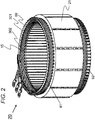
- FIG. 1 is a cross sectional view illustrating the dynamo-electric machine including a stator, according to the present invention.
- a dynamo-electric machine 10 includes a housing 50, a stator 20, a stator core 21, a stator coil 60, and a rotor 11.
- the stator 20 is fixed on an inner circumferential side of the housing 50.
- the rotor 11 is rotatably supported on an inner circumferential side of the stator 20.
- the housing 50 constitutes an envelope of an electric motor, molded into a cylindrical shape by cutting a ferrous material such as carbon steel, or casting or pressing cast steel or an aluminum alloy.
- the housing 50 is also referred to as a frame body or a frame.
- a liquid cooling jacket 130 is fixed on an outer circumferential side of the housing 50.
- An inner circumferential wall of the liquid cooling jacket 130 and an outer circumferential wall of the housing 50 constitute a refrigerant passage 153 of a liquid refrigerant RF such as oil.
- the refrigerant passage 153 is formed so as not to leak liquid.
- the liquid cooling jacket 130 houses bearings 144 and 145, and is also referred to as a bearing bracket.
- the refrigerant RF passes through the refrigerant passage 153, and flows out toward the stator 20 from the refrigerant outlets 154 and 155 to cool the stator 20.
- the refrigerant RF is stored in a refrigerant (oil) storage space 150.
- the stator 20 includes the stator core 21 and the stator coil 60.
- the stator core 21 is manufactured by laminating silicon steel plates.
- the stator coil 60 is wound around many slots 15 provided in an inner circumferential part of the stator core 21. Heat generated in the stator coil 60 is transferred to the liquid cooling jacket 130 through the stator core 21, and is radiated by the refrigerant RF flowing in the liquid cooling jacket 130.
- a join-side coil end 62 which is a coil end of the stator coil 60 is provided at one end of the stator 20 in the axial direction.
- the join-side coil end 62 has a joining portion joined by welding.
- a counter-join-side coil end 61 which is a coil end of the stator coil 60 is provided at the other end of the stator 20 in the axial direction. Details of the join-side coil end 62 and the counter-join-side coil end 61 will be described below.
- the rotor 11 includes a rotor core 12 and a rotation axis 13.
- the rotor core 12 is manufactured by laminating silicon steel plates.
- the rotation axis 13 is fixed in the center of the rotor core 12.
- the rotation axis 13 is rotatably held by the bearings 144 and 145 mounted in the liquid cooling jacket 130, and rotates at a predetermined position in the stator 20 and at a position opposed to the stator 20.
- the rotor 11 is provided with a permanent magnet 18 and an end ring (not illustrated).
- the stator 20 is inserted into the housing 50 and attached to an inner circumferential wall of the housing 50, and then the rotor 11 is inserted into the stator 20. Subsequently, what has been thus obtained is incorporated into the liquid cooling jacket 130 such that the bearings 144 and 145 are fitted to the rotation axis 13.
- the stator 20 includes the stator core 21 and the stator coil 60 wound around the many slots 15 provided in the inner circumferential part of the stator core 21.
- a conductor copper wire in the present Example having a substantially rectangular cross section is used for the stator coil 60. This improves a space factor in the slot and improves an efficiency of the dynamo-electric machine.
- a slot liner 302 is disposed in each slot 15 to secure electrical insulation between the stator core 21 and the stator coil 60.
- the slot liner 302 is formed into a B shape or an S shape so as to wrap the copper wire.
- Insulating paper 301 is disposed annularly for insulating the coils of the stator coil 60 from each other.
- the whole stator coil 60 is coated using the resin composition 601 only. That is, both the join-side coil end 62 and the counter-join-side coil end 61 are coated using one kind of resin composition, i.e., the resin composition 601. This is an excellent point of the present invention, different from the prior art. As described above, by coating the stator coil 60 using the resin composition 601 only, manufacturing using one kind of manufacturing equipment is possible.
- the "region except for the join-side coil end in the stator coil 60" includes the counter-join-side coil end 61 and a region inserted into the slot 15 in the stator coil 60. As described above, when two kinds of resin compositions are used, two kinds of manufacturing equipments are necessary.
- the stator coil 60 of the stator 20 in the dynamo-electric machine 10 of the present invention is coated using the resin composition 601 only, that is, using one kind of resin composition.
- a coating situation of the join-side coil end 62 ( FIG. 6 ) and a coating situation of a region except for the join-side coil end 62 ( FIG. 4 ) are illustrated.
- a coating situation of the counter-join-side coil end 61 ( FIG. 4 ) is illustrated.
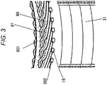
- FIG. 3 is an enlarged view around the counter-join-side coil end 61 of the stator 20 in the dynamo-electric machine 10, seen from an outer circumferential side of the stator 20.
- the stator 20 includes the stator core 21 and the stator coil 60 wound around the many slots 15 provided in the inner circumferential part of the stator core 21.
- the stator coil 60 is formed of a conductor having a substantially rectangular cross section.
- Insulating paper 300 is disposed annularly for insulating the coils from each other.
- the insulating paper 301 is disposed annularly for securing electrical insulation.
- the slot liner 302 is disposed in each slot 15 to secure electrical insulation between the stator core 21 and the stator coil 60.
- FIG. 4 illustrates the coating situation of the counter-join-side coil end 61.
- an insulated coated section 29A coated with an insulating film such as an enameled film is formed in the whole counter-join-side coil end 61.
- the insulated coated section 29A is coated using the resin composition 601 only, and the thickness thereof is almost uniform.
- the coating situation of the counter-join-side coil end 61 is illustrated in the coating situation of the counter-join-side coil end 61 .
- coating situations of the other regions except for the join-side coil end 62 are similar thereto.
- FIG. 5 is an enlarged view around the join-side coil end 62 of the stator 20 in the dynamo-electric machine 10, seen from an inner circumferential side of the stator 20.
- the stator 20 includes the stator core 21 and the stator coil 60 wound around the many slots 15 provided in the inner circumferential part of the stator core 21.
- the stator coil 60 is formed of a conductor having a substantially rectangular cross section.
- the insulating paper 300 is disposed annularly for insulating the coils from each other.
- the insulating paper 301 is disposed annularly for securing electrical insulation.
- a slot liner 302 is disposed in each slot 15 to secure electrical insulation between the stator core 21 and the stator coil 60.
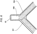
- FIG. 6 illustrates the coating situation of the join-side coil end 62.
- the join-side coil end 62 includes the insulated coated section 29A coated with an insulating film such as an enameled film and a conductor-exposing section 29B in which the insulating film is peeled off and the conductor is exposed for joining.
- the conductor-exposing section 29B is provided at an end of the conductor, and is welded to become a coil end joining portion.
- the insulated coated section 29A and the conductor-exposing section 29B are coated using the resin composition 601 only, and the thicknesses thereof are almost uniform.
- a method for coating a coil portion of the stator 20 using the resin composition 601 for realizing the above-described coating situation will be described.
- a coil as a member for a dynamo-electric machine is impregnated with the resin composition 601 using a dipping method, a drop impregnation method, or the like.
- the impregnation method may be an ordinary method, and is not particularly limited.
- the coil which has been impregnated with the resin is irradiated with an energy ray, and the irradiation part is thereby cured.
- the energy ray is preferably an ultraviolet ray generated by a mercury lamp or the like.
- a wavelength can be selected appropriately according to the photo-radical polymerization initiator as the (D) component.
- the resin composition 601 coated on the stator 20 is cured completely by heating.
- This heating may be performed by an ordinary method such as heating with a warm-air heating furnace or an IH heating furnace, and is not particularly limited. In Examples described below, an example of this coating method will be described.
- an unsaturated-polyester resin is used from viewpoints of cost, an insulation property, permeability, a curing property, and the like.
- a solvent type unsaturated-polyester resin in which the resin is diluted with a solvent or a solvent-free unsaturated-polyester resin in which the resin is not diluted with a solvent can be used.
- the solvent-free unsaturated-polyester resin is more preferable because swelling due to volatilization of a solvent does not occur in curing.
- a non-styrene unsaturated-polyester resin is still more preferable in order to prevent deterioration of characteristics due to volatilization of a component in curing.
- the term “only” does not exclude the presence of an insulating film formed on a conductor in advance, such as an enameled film.
- the term “only” means that an insulating resin provided for imparting an insulating property and a fixing property after the stator coil 60 is molded is the resin composition 601 only and a second resin member in the related art is not used.
- the term “one kind of” used in the "one kind of resin composition” is used to mean the same as “only” described here.
- a winding method of the stator coil 60 in the above embodiment is distributed winding.
- the present invention can be applied also to another winding method such as concentrated winding.
- the dynamo-electric machine in the above embodiment is an inner rotor type dynamo-electric machine.
- the present invention can be similarly applied to an outer rotor type dynamo-electric machine, an axial gap type dynamo-electric machine, and the like.
- the dynamo-electric machine 10 in the above embodiment is a dynamo-electric machine having a permanent magnet type rotor.
- the present invention can be applied to an induction type dynamo-electric machine, a synchronous reluctance type dynamo-electric machine, a dynamo-electric machine having a claw pole type rotor, and the like.
- the joining portion in the present embodiment is joined by welding. However, it is not necessary to limit the joining method to welding.
- the resin composition 601 of the present invention When the present invention is applied to a dynamo-electric machine having a rotor with winding field, it is also possible to use the resin composition 601 of the present invention to the field coil. In this sense, the resin composition 601 of the present invention can be applied to a rotor and a stator which are members for a dynamo-electric machine.
- compositions 1 to 5 were manufactured actually, and were evaluated. Evaluation items were coatability, permeability, adhesiveness, and heat resistance.
- resin compositions in the related art were manufactured as Comparative Examples 1 and 2, and were evaluated similarly. Evaluation results are shown collectively in the table illustrated in FIG. 7 .
- composition examples of the resin composition of the present invention Composition Examples 1 to 5 of the resin composition 601 will be described.
- the Composition Examples 1 to 5 contain:
- composition examples further contain:
- the (C) component is preferably from 1 to 10 parts by weight
- the (D) component is preferably from 0.1 to 5 parts by weight
- the (E) component is preferably from 0.2 to 5 parts by weight, relative to 100 parts by weight of the (A) + (B) component.
- the (C) component less than 1 part by weight does not improve adhesion.
- the (C) component more than 10 parts by weight makes the effect of improving adhesion reach a ceiling, and is not economical.
- the (D) component less than 0.1 parts by weight makes curing insufficient.
- the (D) component more than 5 parts by weight makes the effect of curing reach a ceiling, and is not economical.
- the (E) component less than 0.2 parts by weight makes curing insufficient.
- composition Example 1 an unsaturated-polyester resin composition containing the following (A) to (E) components was used.
- composition Example 2 an unsaturated-polyester resin composition containing the following (A) to (E) components was used.
- composition Example 3 an unsaturated-polyester resin composition containing the following (A) to (E) components was used.
- composition Example 4 an unsaturated-polyester resin composition containing the following (A) to (E) components and other optional components was used.
- composition Example 5 an unsaturated-polyester resin composition containing the following (A) to (D) components and other optional components was used.
- Coatability and permeability The stator 20 was cut into four equal parts to obtain TEST pieces. A resin composition was dropped to the TEST piece from the join-side of the coil 60 at room temperature. Thereafter, the TEST piece was irradiated with an ultraviolet ray using a high pressure mercury lamp for one minute, and then heated with a warm air circulation type thermostat at 120°C. The resulting TEST piece was cut at a position 2 mm apart from an end at the join-side of the coil 60, and a coating thickness was measured as an indicator of coatability.
- a TEST piece in which a resin permeated through the TEST piece to a core end surface at a counter-join-side after decomposition was evaluated as O
- a TEST piece in which a resin did not permeate through the TEST piece to the core end surface at the counter-join-side after decomposition was evaluated as ⁇ .
- Evaluation results are shown in the column (1) in FIG. 7 .
- a resin permeated through the TEST piece to a core end surface at a counter-join-side, and therefore permeability was evaluated as O.
- the coating thicknesses in Composition Example 1, Composition Example 2, Composition Examples 3 and 4, Composition Example 5, and Comparative Examples 1 and 2 were 35 ⁇ m, 30 ⁇ m, 50 ⁇ m, 45 ⁇ m, and 0 ⁇ m, respectively. It is considered that there was a large difference between Composition Examples 1 to 5 and Comparative Examples 1 and 2 because the (D) component for improving coatability was included in Composition Examples 1 to 5.
- Adhesiveness A stracker-like TEST piece was manufactured using an enameled wire (AIW) coated using polyamideimide and having a rectangular cross section of 3 mm ⁇ 2 mm. This TEST piece was impregnated with the resin composition 601, and then heated with a warm air circulation type thermostat at 120°C for two hours. Thereafter, a tensile fracture TEST was performed at 23°C using an autograph DSS-5000 manufactured by Shimadzu Corporation. In the tensile fracture TEST, a distance between fulcrums was 150 mm, a crosshead speed was 5 mm/min, and adhesion was a load when the TEST piece was withdrawn.
- AIW enameled wire
- polyamideimide polyamideimide
- Adhesion in each of Composition Examples 1 and 2 and Comparative Example 1 was 1.0 kN.
- Adhesion in each of Composition Examples 3 to 5 was 1.1 kN.
- Adhesion in Comparative Example 2 was 0.8 kN. It is considered that adhesion only in Comparative Example 2 was small as compared to those in Composition Examples 1 to 5 and Comparative Example 1 because the (C) component for improving adhesiveness was not included only in Comparative Example 2.
- Heat resistanceHeat resistance was determined by an ordinary method using a helical coil TEST method. AIW of ⁇ 1 mm was used for an enameled wire.
- a member for a dynamo-electric machine such as a stator or a rotor, having an excellent insulating property and an excellent cooling property in spite of being small and having a high output.
- the present invention is defined by claim 1 and not limited to Examples described above, but includes various modification examples.
- Examples described above are described in detail in order to describe the present invention so as to be understood easily, and are not necessarily limited to those including all the components described.
- some components in Examples can be deleted or replaced by another component, or another component can be added thereto within the definition of claim 1.
Landscapes
- Chemical & Material Sciences (AREA)
- Engineering & Computer Science (AREA)
- Power Engineering (AREA)
- Physics & Mathematics (AREA)
- Spectroscopy & Molecular Physics (AREA)
- Life Sciences & Earth Sciences (AREA)
- Chemical Kinetics & Catalysis (AREA)
- Materials Engineering (AREA)
- Wood Science & Technology (AREA)
- Organic Chemistry (AREA)
- Insulation, Fastening Of Motor, Generator Windings (AREA)
- Macromonomer-Based Addition Polymer (AREA)
- Organic Insulating Materials (AREA)
Applications Claiming Priority (2)
| Application Number | Priority Date | Filing Date | Title |
|---|---|---|---|
| JP2013143786A JP6057852B2 (ja) | 2013-07-09 | 2013-07-09 | 回転電機用部材、回転電機、および、樹脂組成物 |
| PCT/JP2014/063011 WO2015004987A1 (ja) | 2013-07-09 | 2014-05-16 | 回転電機用部材、回転電機、および、樹脂組成物 |
Publications (3)
| Publication Number | Publication Date |
|---|---|
| EP3021460A1 EP3021460A1 (en) | 2016-05-18 |
| EP3021460A4 EP3021460A4 (en) | 2017-04-19 |
| EP3021460B1 true EP3021460B1 (en) | 2021-11-10 |
Family
ID=52279682
Family Applications (1)
| Application Number | Title | Priority Date | Filing Date |
|---|---|---|---|
| EP14822400.9A Active EP3021460B1 (en) | 2013-07-09 | 2014-05-16 | Resin composition, member for dynamo-electric machine and dynamo-electric machine |
Country Status (5)
| Country | Link |
|---|---|
| US (1) | US9957413B2 (enExample) |
| EP (1) | EP3021460B1 (enExample) |
| JP (1) | JP6057852B2 (enExample) |
| CN (1) | CN105359385B (enExample) |
| WO (1) | WO2015004987A1 (enExample) |
Families Citing this family (3)
| Publication number | Priority date | Publication date | Assignee | Title |
|---|---|---|---|---|
| JP7084126B2 (ja) * | 2017-11-17 | 2022-06-14 | トヨタ自動車株式会社 | ステータの製造方法およびステータ |
| JP2021102748A (ja) * | 2019-12-24 | 2021-07-15 | 昭和電工株式会社 | コイル用ラジカル重合性ワニス |
| WO2025047574A1 (ja) * | 2023-08-29 | 2025-03-06 | 株式会社ダイセル | 硬化性エポキシ組成物 |
Family Cites Families (10)
| Publication number | Priority date | Publication date | Assignee | Title |
|---|---|---|---|---|
| JP3770263B2 (ja) | 1999-07-12 | 2006-04-26 | 株式会社デンソー | 回転電機の製造方法 |
| JP2002050249A (ja) * | 2000-08-01 | 2002-02-15 | Sekisui Chem Co Ltd | 表面被覆線材の製造方法及び表面被覆用組成物 |
| US6740716B2 (en) * | 2001-10-30 | 2004-05-25 | Dow Global Technologies Inc. | Organoborane amine complex polymerization initiators and polymerizable compositions |
| US8025926B2 (en) * | 2008-04-23 | 2011-09-27 | Sabic Innovative Plastics Ip B.V. | Varnish compositions for electrical insulation and method of using the same |
| US8092722B2 (en) * | 2008-09-30 | 2012-01-10 | Sabic Innovative Plastics Ip B.V. | Varnish compositions for electrical insulation and method of using the same |
| US20100151242A1 (en) * | 2008-12-10 | 2010-06-17 | E.I. Du Pont De Nemours And Company | Impregnating compositions |
| EP2432092B1 (en) * | 2009-05-13 | 2016-05-04 | JSR Corporation | Kit for electrical wire water-sealing material, electrical wire water-sealing material, water-sealing member, water-sealed electrical wire, and water-sealing method |
| JP5337762B2 (ja) * | 2010-06-25 | 2013-11-06 | 株式会社日立産機システム | コイル固着用不飽和ポリエステル樹脂組成物 |
| JP5572055B2 (ja) | 2010-10-20 | 2014-08-13 | 株式会社日立産機システム | 接合部絶縁構造を有する電気機器 |
| JP5690759B2 (ja) * | 2012-02-15 | 2015-03-25 | 株式会社日立製作所 | 熱硬化性樹脂組成物、硬化物、導線、電気機器用コイル及び電気機器 |
-
2013
- 2013-07-09 JP JP2013143786A patent/JP6057852B2/ja active Active
-
2014
- 2014-05-16 WO PCT/JP2014/063011 patent/WO2015004987A1/ja not_active Ceased
- 2014-05-16 CN CN201480039028.4A patent/CN105359385B/zh active Active
- 2014-05-16 EP EP14822400.9A patent/EP3021460B1/en active Active
- 2014-05-16 US US14/902,442 patent/US9957413B2/en active Active
Non-Patent Citations (1)
| Title |
|---|
| None * |
Also Published As
| Publication number | Publication date |
|---|---|
| EP3021460A4 (en) | 2017-04-19 |
| JP2015019457A (ja) | 2015-01-29 |
| US9957413B2 (en) | 2018-05-01 |
| JP6057852B2 (ja) | 2017-01-11 |
| CN105359385B (zh) | 2018-12-07 |
| US20160376466A1 (en) | 2016-12-29 |
| EP3021460A1 (en) | 2016-05-18 |
| CN105359385A (zh) | 2016-02-24 |
| WO2015004987A1 (ja) | 2015-01-15 |
Similar Documents
| Publication | Publication Date | Title |
|---|---|---|
| CN108137947B (zh) | 无溶剂型清漆组合物、绝缘线圈及其制造方法、旋转机以及密闭型电动压缩机 | |
| EP3021460B1 (en) | Resin composition, member for dynamo-electric machine and dynamo-electric machine | |
| JP5337762B2 (ja) | コイル固着用不飽和ポリエステル樹脂組成物 | |
| WO2021210241A1 (ja) | コイル用絶縁接着部材および電気機器 | |
| CN110892019B (zh) | 不饱和聚酯树脂组合物及使用其的电气设备 | |
| CN112566968B (zh) | 一种旋转电机的定子的制造方法 | |
| WO2022054381A1 (ja) | 絶縁紙、回転電機用固定子および回転電機 | |
| JP6375224B2 (ja) | 熱硬化性樹脂組成物および該組成物を用いた回転電機 | |
| TW200838938A (en) | Resins of unsaturated polyesters functionalized by unsaturated cycloaliphatic imides, for coatings and moulding compositions | |
| JP2010144109A (ja) | 熱硬化性樹脂組成物 | |
| WO2024100963A1 (ja) | 固定子及び回転電機 | |
| JP7788283B2 (ja) | 回転電機の固定子 | |
| US9972415B2 (en) | Resin compositions comprising sorbic esters | |
| JP2023101093A (ja) | 回転電機の固定子 | |
| JP2016036192A (ja) | 回転電機の固定子、およびこれを備えた回転電機 | |
| JP2012241076A (ja) | 高耐熱性熱硬化性樹脂組成物およびそれを用いた電気機器 | |
| JP5202439B2 (ja) | 熱硬化性樹脂組成物 |
Legal Events
| Date | Code | Title | Description |
|---|---|---|---|
| PUAI | Public reference made under article 153(3) epc to a published international application that has entered the european phase |
Free format text: ORIGINAL CODE: 0009012 |
|
| 17P | Request for examination filed |
Effective date: 20160209 |
|
| AK | Designated contracting states |
Kind code of ref document: A1 Designated state(s): AL AT BE BG CH CY CZ DE DK EE ES FI FR GB GR HR HU IE IS IT LI LT LU LV MC MK MT NL NO PL PT RO RS SE SI SK SM TR |
|
| AX | Request for extension of the european patent |
Extension state: BA ME |
|
| DAX | Request for extension of the european patent (deleted) | ||
| A4 | Supplementary search report drawn up and despatched |
Effective date: 20170317 |
|
| RIC1 | Information provided on ipc code assigned before grant |
Ipc: H01F 5/06 20060101ALI20170313BHEP Ipc: C09D 167/00 20060101ALI20170313BHEP Ipc: H01B 3/42 20060101ALI20170313BHEP Ipc: H02K 3/38 20060101ALN20170313BHEP Ipc: H01B 3/30 20060101ALI20170313BHEP Ipc: H02K 3/30 20060101AFI20170313BHEP |
|
| STAA | Information on the status of an ep patent application or granted ep patent |
Free format text: STATUS: EXAMINATION IS IN PROGRESS |
|
| 17Q | First examination report despatched |
Effective date: 20190425 |
|
| GRAP | Despatch of communication of intention to grant a patent |
Free format text: ORIGINAL CODE: EPIDOSNIGR1 |
|
| STAA | Information on the status of an ep patent application or granted ep patent |
Free format text: STATUS: GRANT OF PATENT IS INTENDED |
|
| RIC1 | Information provided on ipc code assigned before grant |
Ipc: H02K 3/38 20060101ALN20210330BHEP Ipc: C09D 167/00 20060101ALI20210330BHEP Ipc: H01F 5/06 20060101ALI20210330BHEP Ipc: H01B 3/42 20060101ALI20210330BHEP Ipc: H01B 3/30 20060101ALI20210330BHEP Ipc: H02K 3/30 20060101AFI20210330BHEP |
|
| INTG | Intention to grant announced |
Effective date: 20210422 |
|
| GRAS | Grant fee paid |
Free format text: ORIGINAL CODE: EPIDOSNIGR3 |
|
| RAP3 | Party data changed (applicant data changed or rights of an application transferred) |
Owner name: HITACHI ASTEMO, LTD. |
|
| RIN1 | Information on inventor provided before grant (corrected) |
Inventor name: MATSUNOBU YUTAKA Inventor name: HONMA MASAHIKO Inventor name: YAMAMURA SATOSHI Inventor name: MURAKI TAKAHITO |
|
| GRAA | (expected) grant |
Free format text: ORIGINAL CODE: 0009210 |
|
| STAA | Information on the status of an ep patent application or granted ep patent |
Free format text: STATUS: THE PATENT HAS BEEN GRANTED |
|
| AK | Designated contracting states |
Kind code of ref document: B1 Designated state(s): AL AT BE BG CH CY CZ DE DK EE ES FI FR GB GR HR HU IE IS IT LI LT LU LV MC MK MT NL NO PL PT RO RS SE SI SK SM TR |
|
| REG | Reference to a national code |
Ref country code: GB Ref legal event code: FG4D |
|
| REG | Reference to a national code |
Ref country code: AT Ref legal event code: REF Ref document number: 1446982 Country of ref document: AT Kind code of ref document: T Effective date: 20211115 Ref country code: CH Ref legal event code: EP |
|
| REG | Reference to a national code |
Ref country code: DE Ref legal event code: R096 Ref document number: 602014081211 Country of ref document: DE |
|
| REG | Reference to a national code |
Ref country code: IE Ref legal event code: FG4D |
|
| REG | Reference to a national code |
Ref country code: LT Ref legal event code: MG9D |
|
| REG | Reference to a national code |
Ref country code: NL Ref legal event code: MP Effective date: 20211110 |
|
| REG | Reference to a national code |
Ref country code: AT Ref legal event code: MK05 Ref document number: 1446982 Country of ref document: AT Kind code of ref document: T Effective date: 20211110 |
|
| PG25 | Lapsed in a contracting state [announced via postgrant information from national office to epo] |
Ref country code: RS Free format text: LAPSE BECAUSE OF FAILURE TO SUBMIT A TRANSLATION OF THE DESCRIPTION OR TO PAY THE FEE WITHIN THE PRESCRIBED TIME-LIMIT Effective date: 20211110 Ref country code: LT Free format text: LAPSE BECAUSE OF FAILURE TO SUBMIT A TRANSLATION OF THE DESCRIPTION OR TO PAY THE FEE WITHIN THE PRESCRIBED TIME-LIMIT Effective date: 20211110 Ref country code: FI Free format text: LAPSE BECAUSE OF FAILURE TO SUBMIT A TRANSLATION OF THE DESCRIPTION OR TO PAY THE FEE WITHIN THE PRESCRIBED TIME-LIMIT Effective date: 20211110 Ref country code: BG Free format text: LAPSE BECAUSE OF FAILURE TO SUBMIT A TRANSLATION OF THE DESCRIPTION OR TO PAY THE FEE WITHIN THE PRESCRIBED TIME-LIMIT Effective date: 20220210 Ref country code: AT Free format text: LAPSE BECAUSE OF FAILURE TO SUBMIT A TRANSLATION OF THE DESCRIPTION OR TO PAY THE FEE WITHIN THE PRESCRIBED TIME-LIMIT Effective date: 20211110 |
|
| PG25 | Lapsed in a contracting state [announced via postgrant information from national office to epo] |
Ref country code: IS Free format text: LAPSE BECAUSE OF FAILURE TO SUBMIT A TRANSLATION OF THE DESCRIPTION OR TO PAY THE FEE WITHIN THE PRESCRIBED TIME-LIMIT Effective date: 20220310 Ref country code: SE Free format text: LAPSE BECAUSE OF FAILURE TO SUBMIT A TRANSLATION OF THE DESCRIPTION OR TO PAY THE FEE WITHIN THE PRESCRIBED TIME-LIMIT Effective date: 20211110 Ref country code: PT Free format text: LAPSE BECAUSE OF FAILURE TO SUBMIT A TRANSLATION OF THE DESCRIPTION OR TO PAY THE FEE WITHIN THE PRESCRIBED TIME-LIMIT Effective date: 20220310 Ref country code: PL Free format text: LAPSE BECAUSE OF FAILURE TO SUBMIT A TRANSLATION OF THE DESCRIPTION OR TO PAY THE FEE WITHIN THE PRESCRIBED TIME-LIMIT Effective date: 20211110 Ref country code: NO Free format text: LAPSE BECAUSE OF FAILURE TO SUBMIT A TRANSLATION OF THE DESCRIPTION OR TO PAY THE FEE WITHIN THE PRESCRIBED TIME-LIMIT Effective date: 20220210 Ref country code: NL Free format text: LAPSE BECAUSE OF FAILURE TO SUBMIT A TRANSLATION OF THE DESCRIPTION OR TO PAY THE FEE WITHIN THE PRESCRIBED TIME-LIMIT Effective date: 20211110 Ref country code: LV Free format text: LAPSE BECAUSE OF FAILURE TO SUBMIT A TRANSLATION OF THE DESCRIPTION OR TO PAY THE FEE WITHIN THE PRESCRIBED TIME-LIMIT Effective date: 20211110 Ref country code: HR Free format text: LAPSE BECAUSE OF FAILURE TO SUBMIT A TRANSLATION OF THE DESCRIPTION OR TO PAY THE FEE WITHIN THE PRESCRIBED TIME-LIMIT Effective date: 20211110 Ref country code: GR Free format text: LAPSE BECAUSE OF FAILURE TO SUBMIT A TRANSLATION OF THE DESCRIPTION OR TO PAY THE FEE WITHIN THE PRESCRIBED TIME-LIMIT Effective date: 20220211 Ref country code: ES Free format text: LAPSE BECAUSE OF FAILURE TO SUBMIT A TRANSLATION OF THE DESCRIPTION OR TO PAY THE FEE WITHIN THE PRESCRIBED TIME-LIMIT Effective date: 20211110 |
|
| PG25 | Lapsed in a contracting state [announced via postgrant information from national office to epo] |
Ref country code: SM Free format text: LAPSE BECAUSE OF FAILURE TO SUBMIT A TRANSLATION OF THE DESCRIPTION OR TO PAY THE FEE WITHIN THE PRESCRIBED TIME-LIMIT Effective date: 20211110 Ref country code: SK Free format text: LAPSE BECAUSE OF FAILURE TO SUBMIT A TRANSLATION OF THE DESCRIPTION OR TO PAY THE FEE WITHIN THE PRESCRIBED TIME-LIMIT Effective date: 20211110 Ref country code: RO Free format text: LAPSE BECAUSE OF FAILURE TO SUBMIT A TRANSLATION OF THE DESCRIPTION OR TO PAY THE FEE WITHIN THE PRESCRIBED TIME-LIMIT Effective date: 20211110 Ref country code: EE Free format text: LAPSE BECAUSE OF FAILURE TO SUBMIT A TRANSLATION OF THE DESCRIPTION OR TO PAY THE FEE WITHIN THE PRESCRIBED TIME-LIMIT Effective date: 20211110 Ref country code: DK Free format text: LAPSE BECAUSE OF FAILURE TO SUBMIT A TRANSLATION OF THE DESCRIPTION OR TO PAY THE FEE WITHIN THE PRESCRIBED TIME-LIMIT Effective date: 20211110 Ref country code: CZ Free format text: LAPSE BECAUSE OF FAILURE TO SUBMIT A TRANSLATION OF THE DESCRIPTION OR TO PAY THE FEE WITHIN THE PRESCRIBED TIME-LIMIT Effective date: 20211110 |
|
| REG | Reference to a national code |
Ref country code: DE Ref legal event code: R097 Ref document number: 602014081211 Country of ref document: DE |
|
| PLBE | No opposition filed within time limit |
Free format text: ORIGINAL CODE: 0009261 |
|
| STAA | Information on the status of an ep patent application or granted ep patent |
Free format text: STATUS: NO OPPOSITION FILED WITHIN TIME LIMIT |
|
| 26N | No opposition filed |
Effective date: 20220811 |
|
| PG25 | Lapsed in a contracting state [announced via postgrant information from national office to epo] |
Ref country code: AL Free format text: LAPSE BECAUSE OF FAILURE TO SUBMIT A TRANSLATION OF THE DESCRIPTION OR TO PAY THE FEE WITHIN THE PRESCRIBED TIME-LIMIT Effective date: 20211110 |
|
| PG25 | Lapsed in a contracting state [announced via postgrant information from national office to epo] |
Ref country code: SI Free format text: LAPSE BECAUSE OF FAILURE TO SUBMIT A TRANSLATION OF THE DESCRIPTION OR TO PAY THE FEE WITHIN THE PRESCRIBED TIME-LIMIT Effective date: 20211110 |
|
| REG | Reference to a national code |
Ref country code: CH Ref legal event code: PL |
|
| REG | Reference to a national code |
Ref country code: BE Ref legal event code: MM Effective date: 20220531 |
|
| GBPC | Gb: european patent ceased through non-payment of renewal fee |
Effective date: 20220516 |
|
| PG25 | Lapsed in a contracting state [announced via postgrant information from national office to epo] |
Ref country code: MC Free format text: LAPSE BECAUSE OF FAILURE TO SUBMIT A TRANSLATION OF THE DESCRIPTION OR TO PAY THE FEE WITHIN THE PRESCRIBED TIME-LIMIT Effective date: 20211110 Ref country code: LU Free format text: LAPSE BECAUSE OF NON-PAYMENT OF DUE FEES Effective date: 20220516 Ref country code: LI Free format text: LAPSE BECAUSE OF NON-PAYMENT OF DUE FEES Effective date: 20220531 Ref country code: CH Free format text: LAPSE BECAUSE OF NON-PAYMENT OF DUE FEES Effective date: 20220531 |
|
| PG25 | Lapsed in a contracting state [announced via postgrant information from national office to epo] |
Ref country code: IE Free format text: LAPSE BECAUSE OF NON-PAYMENT OF DUE FEES Effective date: 20220516 Ref country code: FR Free format text: LAPSE BECAUSE OF NON-PAYMENT OF DUE FEES Effective date: 20220531 |
|
| PG25 | Lapsed in a contracting state [announced via postgrant information from national office to epo] |
Ref country code: IT Free format text: LAPSE BECAUSE OF FAILURE TO SUBMIT A TRANSLATION OF THE DESCRIPTION OR TO PAY THE FEE WITHIN THE PRESCRIBED TIME-LIMIT Effective date: 20211110 Ref country code: GB Free format text: LAPSE BECAUSE OF NON-PAYMENT OF DUE FEES Effective date: 20220516 Ref country code: BE Free format text: LAPSE BECAUSE OF NON-PAYMENT OF DUE FEES Effective date: 20220531 |
|
| PG25 | Lapsed in a contracting state [announced via postgrant information from national office to epo] |
Ref country code: HU Free format text: LAPSE BECAUSE OF FAILURE TO SUBMIT A TRANSLATION OF THE DESCRIPTION OR TO PAY THE FEE WITHIN THE PRESCRIBED TIME-LIMIT; INVALID AB INITIO Effective date: 20140516 |
|
| PG25 | Lapsed in a contracting state [announced via postgrant information from national office to epo] |
Ref country code: MK Free format text: LAPSE BECAUSE OF FAILURE TO SUBMIT A TRANSLATION OF THE DESCRIPTION OR TO PAY THE FEE WITHIN THE PRESCRIBED TIME-LIMIT Effective date: 20211110 Ref country code: CY Free format text: LAPSE BECAUSE OF FAILURE TO SUBMIT A TRANSLATION OF THE DESCRIPTION OR TO PAY THE FEE WITHIN THE PRESCRIBED TIME-LIMIT Effective date: 20211110 |
|
| PG25 | Lapsed in a contracting state [announced via postgrant information from national office to epo] |
Ref country code: TR Free format text: LAPSE BECAUSE OF FAILURE TO SUBMIT A TRANSLATION OF THE DESCRIPTION OR TO PAY THE FEE WITHIN THE PRESCRIBED TIME-LIMIT Effective date: 20211110 |
|
| PG25 | Lapsed in a contracting state [announced via postgrant information from national office to epo] |
Ref country code: MT Free format text: LAPSE BECAUSE OF FAILURE TO SUBMIT A TRANSLATION OF THE DESCRIPTION OR TO PAY THE FEE WITHIN THE PRESCRIBED TIME-LIMIT Effective date: 20211110 |
|
| PGFP | Annual fee paid to national office [announced via postgrant information from national office to epo] |
Ref country code: DE Payment date: 20250402 Year of fee payment: 12 |