EP3020530B1 - Simulationsvorrichtung, simulationsverfahren und simulationsprogramm - Google Patents
Simulationsvorrichtung, simulationsverfahren und simulationsprogramm Download PDFInfo
- Publication number
- EP3020530B1 EP3020530B1 EP15194031.9A EP15194031A EP3020530B1 EP 3020530 B1 EP3020530 B1 EP 3020530B1 EP 15194031 A EP15194031 A EP 15194031A EP 3020530 B1 EP3020530 B1 EP 3020530B1
- Authority
- EP
- European Patent Office
- Prior art keywords
- fluid
- analysis
- flow analysis
- dimensional
- object area
- Prior art date
- Legal status (The legal status is an assumption and is not a legal conclusion. Google has not performed a legal analysis and makes no representation as to the accuracy of the status listed.)
- Active
Links
Images


Classifications
-
- B—PERFORMING OPERATIONS; TRANSPORTING
- B29—WORKING OF PLASTICS; WORKING OF SUBSTANCES IN A PLASTIC STATE IN GENERAL
- B29B—PREPARATION OR PRETREATMENT OF THE MATERIAL TO BE SHAPED; MAKING GRANULES OR PREFORMS; RECOVERY OF PLASTICS OR OTHER CONSTITUENTS OF WASTE MATERIAL CONTAINING PLASTICS
- B29B7/00—Mixing; Kneading
- B29B7/30—Mixing; Kneading continuous, with mechanical mixing or kneading devices
- B29B7/58—Component parts, details or accessories; Auxiliary operations
- B29B7/72—Measuring, controlling or regulating
- B29B7/726—Measuring properties of mixture, e.g. temperature or density
-
- B—PERFORMING OPERATIONS; TRANSPORTING
- B29—WORKING OF PLASTICS; WORKING OF SUBSTANCES IN A PLASTIC STATE IN GENERAL
- B29B—PREPARATION OR PRETREATMENT OF THE MATERIAL TO BE SHAPED; MAKING GRANULES OR PREFORMS; RECOVERY OF PLASTICS OR OTHER CONSTITUENTS OF WASTE MATERIAL CONTAINING PLASTICS
- B29B7/00—Mixing; Kneading
- B29B7/30—Mixing; Kneading continuous, with mechanical mixing or kneading devices
- B29B7/34—Mixing; Kneading continuous, with mechanical mixing or kneading devices with movable mixing or kneading devices
- B29B7/38—Mixing; Kneading continuous, with mechanical mixing or kneading devices with movable mixing or kneading devices rotary
- B29B7/46—Mixing; Kneading continuous, with mechanical mixing or kneading devices with movable mixing or kneading devices rotary with more than one shaft
- B29B7/48—Mixing; Kneading continuous, with mechanical mixing or kneading devices with movable mixing or kneading devices rotary with more than one shaft with intermeshing devices, e.g. screws
-
- B—PERFORMING OPERATIONS; TRANSPORTING
- B29—WORKING OF PLASTICS; WORKING OF SUBSTANCES IN A PLASTIC STATE IN GENERAL
- B29B—PREPARATION OR PRETREATMENT OF THE MATERIAL TO BE SHAPED; MAKING GRANULES OR PREFORMS; RECOVERY OF PLASTICS OR OTHER CONSTITUENTS OF WASTE MATERIAL CONTAINING PLASTICS
- B29B7/00—Mixing; Kneading
- B29B7/30—Mixing; Kneading continuous, with mechanical mixing or kneading devices
- B29B7/58—Component parts, details or accessories; Auxiliary operations
- B29B7/72—Measuring, controlling or regulating
- B29B7/728—Measuring data of the driving system, e.g. torque, speed, power, vibration
-
- B—PERFORMING OPERATIONS; TRANSPORTING
- B29—WORKING OF PLASTICS; WORKING OF SUBSTANCES IN A PLASTIC STATE IN GENERAL
- B29C—SHAPING OR JOINING OF PLASTICS; SHAPING OF MATERIAL IN A PLASTIC STATE, NOT OTHERWISE PROVIDED FOR; AFTER-TREATMENT OF THE SHAPED PRODUCTS, e.g. REPAIRING
- B29C48/00—Extrusion moulding, i.e. expressing the moulding material through a die or nozzle which imparts the desired form; Apparatus therefor
- B29C48/25—Component parts, details or accessories; Auxiliary operations
- B29C48/251—Design of extruder parts, e.g. by modelling based on mathematical theories or experiments
- B29C48/2511—Design of extruder parts, e.g. by modelling based on mathematical theories or experiments by modelling material flow, e.g. melt interaction with screw and barrel
- B29C48/2513—Design of extruder parts, e.g. by modelling based on mathematical theories or experiments by modelling material flow, e.g. melt interaction with screw and barrel in the plasticising zone
-
- B—PERFORMING OPERATIONS; TRANSPORTING
- B29—WORKING OF PLASTICS; WORKING OF SUBSTANCES IN A PLASTIC STATE IN GENERAL
- B29C—SHAPING OR JOINING OF PLASTICS; SHAPING OF MATERIAL IN A PLASTIC STATE, NOT OTHERWISE PROVIDED FOR; AFTER-TREATMENT OF THE SHAPED PRODUCTS, e.g. REPAIRING
- B29C48/00—Extrusion moulding, i.e. expressing the moulding material through a die or nozzle which imparts the desired form; Apparatus therefor
- B29C48/25—Component parts, details or accessories; Auxiliary operations
- B29C48/251—Design of extruder parts, e.g. by modelling based on mathematical theories or experiments
- B29C48/2517—Design of extruder parts, e.g. by modelling based on mathematical theories or experiments of intermeshing screws
-
- B—PERFORMING OPERATIONS; TRANSPORTING
- B29—WORKING OF PLASTICS; WORKING OF SUBSTANCES IN A PLASTIC STATE IN GENERAL
- B29C—SHAPING OR JOINING OF PLASTICS; SHAPING OF MATERIAL IN A PLASTIC STATE, NOT OTHERWISE PROVIDED FOR; AFTER-TREATMENT OF THE SHAPED PRODUCTS, e.g. REPAIRING
- B29C48/00—Extrusion moulding, i.e. expressing the moulding material through a die or nozzle which imparts the desired form; Apparatus therefor
- B29C48/25—Component parts, details or accessories; Auxiliary operations
- B29C48/256—Exchangeable extruder parts
- B29C48/2561—Mounting or handling of the screw
-
- B—PERFORMING OPERATIONS; TRANSPORTING
- B29—WORKING OF PLASTICS; WORKING OF SUBSTANCES IN A PLASTIC STATE IN GENERAL
- B29C—SHAPING OR JOINING OF PLASTICS; SHAPING OF MATERIAL IN A PLASTIC STATE, NOT OTHERWISE PROVIDED FOR; AFTER-TREATMENT OF THE SHAPED PRODUCTS, e.g. REPAIRING
- B29C48/00—Extrusion moulding, i.e. expressing the moulding material through a die or nozzle which imparts the desired form; Apparatus therefor
- B29C48/25—Component parts, details or accessories; Auxiliary operations
- B29C48/36—Means for plasticising or homogenising the moulding material or forcing it through the nozzle or die
- B29C48/395—Means for plasticising or homogenising the moulding material or forcing it through the nozzle or die using screws surrounded by a cooperating barrel, e.g. single screw extruders
- B29C48/40—Means for plasticising or homogenising the moulding material or forcing it through the nozzle or die using screws surrounded by a cooperating barrel, e.g. single screw extruders using two or more parallel screws or at least two parallel non-intermeshing screws, e.g. twin screw extruders
- B29C48/402—Means for plasticising or homogenising the moulding material or forcing it through the nozzle or die using screws surrounded by a cooperating barrel, e.g. single screw extruders using two or more parallel screws or at least two parallel non-intermeshing screws, e.g. twin screw extruders the screws having intermeshing parts
-
- B—PERFORMING OPERATIONS; TRANSPORTING
- B29—WORKING OF PLASTICS; WORKING OF SUBSTANCES IN A PLASTIC STATE IN GENERAL
- B29C—SHAPING OR JOINING OF PLASTICS; SHAPING OF MATERIAL IN A PLASTIC STATE, NOT OTHERWISE PROVIDED FOR; AFTER-TREATMENT OF THE SHAPED PRODUCTS, e.g. REPAIRING
- B29C48/00—Extrusion moulding, i.e. expressing the moulding material through a die or nozzle which imparts the desired form; Apparatus therefor
- B29C48/25—Component parts, details or accessories; Auxiliary operations
- B29C48/36—Means for plasticising or homogenising the moulding material or forcing it through the nozzle or die
- B29C48/50—Details of extruders
- B29C48/505—Screws
- B29C48/507—Screws characterised by the material or their manufacturing process
-
- B—PERFORMING OPERATIONS; TRANSPORTING
- B29—WORKING OF PLASTICS; WORKING OF SUBSTANCES IN A PLASTIC STATE IN GENERAL
- B29C—SHAPING OR JOINING OF PLASTICS; SHAPING OF MATERIAL IN A PLASTIC STATE, NOT OTHERWISE PROVIDED FOR; AFTER-TREATMENT OF THE SHAPED PRODUCTS, e.g. REPAIRING
- B29C48/00—Extrusion moulding, i.e. expressing the moulding material through a die or nozzle which imparts the desired form; Apparatus therefor
- B29C48/25—Component parts, details or accessories; Auxiliary operations
- B29C48/36—Means for plasticising or homogenising the moulding material or forcing it through the nozzle or die
- B29C48/50—Details of extruders
- B29C48/505—Screws
- B29C48/57—Screws provided with kneading disc-like elements, e.g. with oval-shaped elements
-
- B—PERFORMING OPERATIONS; TRANSPORTING
- B29—WORKING OF PLASTICS; WORKING OF SUBSTANCES IN A PLASTIC STATE IN GENERAL
- B29C—SHAPING OR JOINING OF PLASTICS; SHAPING OF MATERIAL IN A PLASTIC STATE, NOT OTHERWISE PROVIDED FOR; AFTER-TREATMENT OF THE SHAPED PRODUCTS, e.g. REPAIRING
- B29C48/00—Extrusion moulding, i.e. expressing the moulding material through a die or nozzle which imparts the desired form; Apparatus therefor
- B29C48/25—Component parts, details or accessories; Auxiliary operations
- B29C48/92—Measuring, controlling or regulating
-
- B—PERFORMING OPERATIONS; TRANSPORTING
- B29—WORKING OF PLASTICS; WORKING OF SUBSTANCES IN A PLASTIC STATE IN GENERAL
- B29B—PREPARATION OR PRETREATMENT OF THE MATERIAL TO BE SHAPED; MAKING GRANULES OR PREFORMS; RECOVERY OF PLASTICS OR OTHER CONSTITUENTS OF WASTE MATERIAL CONTAINING PLASTICS
- B29B7/00—Mixing; Kneading
- B29B7/30—Mixing; Kneading continuous, with mechanical mixing or kneading devices
- B29B7/34—Mixing; Kneading continuous, with mechanical mixing or kneading devices with movable mixing or kneading devices
- B29B7/38—Mixing; Kneading continuous, with mechanical mixing or kneading devices with movable mixing or kneading devices rotary
- B29B7/40—Mixing; Kneading continuous, with mechanical mixing or kneading devices with movable mixing or kneading devices rotary with single shaft
- B29B7/42—Mixing; Kneading continuous, with mechanical mixing or kneading devices with movable mixing or kneading devices rotary with single shaft with screw or helix
-
- B—PERFORMING OPERATIONS; TRANSPORTING
- B29—WORKING OF PLASTICS; WORKING OF SUBSTANCES IN A PLASTIC STATE IN GENERAL
- B29B—PREPARATION OR PRETREATMENT OF THE MATERIAL TO BE SHAPED; MAKING GRANULES OR PREFORMS; RECOVERY OF PLASTICS OR OTHER CONSTITUENTS OF WASTE MATERIAL CONTAINING PLASTICS
- B29B7/00—Mixing; Kneading
- B29B7/30—Mixing; Kneading continuous, with mechanical mixing or kneading devices
- B29B7/34—Mixing; Kneading continuous, with mechanical mixing or kneading devices with movable mixing or kneading devices
- B29B7/38—Mixing; Kneading continuous, with mechanical mixing or kneading devices with movable mixing or kneading devices rotary
- B29B7/46—Mixing; Kneading continuous, with mechanical mixing or kneading devices with movable mixing or kneading devices rotary with more than one shaft
-
- B—PERFORMING OPERATIONS; TRANSPORTING
- B29—WORKING OF PLASTICS; WORKING OF SUBSTANCES IN A PLASTIC STATE IN GENERAL
- B29C—SHAPING OR JOINING OF PLASTICS; SHAPING OF MATERIAL IN A PLASTIC STATE, NOT OTHERWISE PROVIDED FOR; AFTER-TREATMENT OF THE SHAPED PRODUCTS, e.g. REPAIRING
- B29C2948/00—Indexing scheme relating to extrusion moulding
- B29C2948/92—Measuring, controlling or regulating
- B29C2948/92009—Measured parameter
- B29C2948/92019—Pressure
-
- B—PERFORMING OPERATIONS; TRANSPORTING
- B29—WORKING OF PLASTICS; WORKING OF SUBSTANCES IN A PLASTIC STATE IN GENERAL
- B29C—SHAPING OR JOINING OF PLASTICS; SHAPING OF MATERIAL IN A PLASTIC STATE, NOT OTHERWISE PROVIDED FOR; AFTER-TREATMENT OF THE SHAPED PRODUCTS, e.g. REPAIRING
- B29C2948/00—Indexing scheme relating to extrusion moulding
- B29C2948/92—Measuring, controlling or regulating
- B29C2948/92009—Measured parameter
- B29C2948/92085—Velocity
- B29C2948/92104—Flow or feed rate
-
- B—PERFORMING OPERATIONS; TRANSPORTING
- B29—WORKING OF PLASTICS; WORKING OF SUBSTANCES IN A PLASTIC STATE IN GENERAL
- B29C—SHAPING OR JOINING OF PLASTICS; SHAPING OF MATERIAL IN A PLASTIC STATE, NOT OTHERWISE PROVIDED FOR; AFTER-TREATMENT OF THE SHAPED PRODUCTS, e.g. REPAIRING
- B29C2948/00—Indexing scheme relating to extrusion moulding
- B29C2948/92—Measuring, controlling or regulating
- B29C2948/92009—Measured parameter
- B29C2948/922—Viscosity; Melt flow index [MFI]; Molecular weight
-
- B—PERFORMING OPERATIONS; TRANSPORTING
- B29—WORKING OF PLASTICS; WORKING OF SUBSTANCES IN A PLASTIC STATE IN GENERAL
- B29C—SHAPING OR JOINING OF PLASTICS; SHAPING OF MATERIAL IN A PLASTIC STATE, NOT OTHERWISE PROVIDED FOR; AFTER-TREATMENT OF THE SHAPED PRODUCTS, e.g. REPAIRING
- B29C2948/00—Indexing scheme relating to extrusion moulding
- B29C2948/92—Measuring, controlling or regulating
- B29C2948/92009—Measured parameter
- B29C2948/92209—Temperature
-
- B—PERFORMING OPERATIONS; TRANSPORTING
- B29—WORKING OF PLASTICS; WORKING OF SUBSTANCES IN A PLASTIC STATE IN GENERAL
- B29C—SHAPING OR JOINING OF PLASTICS; SHAPING OF MATERIAL IN A PLASTIC STATE, NOT OTHERWISE PROVIDED FOR; AFTER-TREATMENT OF THE SHAPED PRODUCTS, e.g. REPAIRING
- B29C2948/00—Indexing scheme relating to extrusion moulding
- B29C2948/92—Measuring, controlling or regulating
- B29C2948/92323—Location or phase of measurement
- B29C2948/92361—Extrusion unit
- B29C2948/9238—Feeding, melting, plasticising or pumping zones, e.g. the melt itself
Definitions
- a flow path existing between a screw and a cylinder of the extruder is cut along a circumferential direction of the cylinder and thus modeled into two plates, that is, upper and lower plates respectively corresponding to the cylinder wall surface and the screw surface.
- a fluid flow state is arithmetically operated under a condition that the plate corresponding to the screw surface is translated by a distance corresponding to a rotation speed of the screw.
- a flow path as an analysis object is entirely divide into lattice elements, then nodes within the elements are set as calculation points, then the law of conservation of mass and the law of conservation of momentum is discretely applied to each of all the nodes, and physical quantities of the entire flow path can be calculated by solving a simultaneous equation for each of the calculation points.
- this method is considered as a kind of a lattice element method.
- the lattice element method another method such as an FVM (finite volume method) or an FDM (finite difference method) is applied in place of the FEM, depending on software.
- FVM finite volume method
- FDM finite difference method
- respective analysis software using the FAN method and the FEM as described above is applied to respective characteristic analyses, that is, respective analyses matched to information required by a user.
- an integrated analysis incorporating merits of the both methods cannot be realized by single software.
- firstly parameters are set manually so that the operation conditions become the same between the respective software. Then outputted results from the respective software are classified separately.
- An object of the invention is to provide a simulation apparatus, a simulation method and a simulation program each of which can efficiently realize both a low-dimensional fluid-flow analysis and a high-dimensional fluid-flow analysis under the same operation conditions of an extruder.
- a simulation program for executing a fluid-flow analysis of material, the simulation program causing a computer to function as: a low-dimensional analysis unit which performs a low-dimensional fluid-flow analysis of the material in an arithmetic object field of a kneading device, based on setting information, the setting information including: physical property of the material; and configuration data and an operation condition of the kneading device for kneading the material; a selection receiving unit configured to receive, after or before the low-dimensional fluid-flow analysis, selection of an object area as an object of a high-dimensional fluid-flow analysis in the arithmetic object field; a physical quantity extraction unit configured to extract physical quantities of the material relating to the object area, based on a result of the low-dimensional fluid-flow analysis; and a high-dimensional analysis unit configured to perform a high-dimensional fluid-flow analysis of the material in the object area, based on the extracted physical quantities and
- an extruder simulation apparatus which analyzes a twin-screw extruder as an analysis object.
- the extruder simulation apparatus predicts fluid-flow behavior of resin material which is kneaded and molten-plasticized in a screw kneading field (two screws and a flow path space formed within a cylinder) as an arithmetic object field.
- the analysis object is not limited to the twin-screw type but may be a single-screw type or a multi-screw type such as a triple-screw type.
- the CPU 11 executes various kinds of programs such as OS (Operating System), BIOS (Basic Input/output System), application software programs and a coupled analysis program described later each developed on the storage unit 12, thus controlling the extruder simulation apparatus 10.
- the storage unit 12 is a volatile memory such as a so-called RAM (Random Access Memory) and used as a work area of the programs to be executed.
- the input unit 13 receives an input from a user (analysis executor) using the extruder simulation apparatus 10.
- the input unit is a mouse as a pointing device for designating a particular position on a display or a keyboard where plural keys allotted with characters and particular functions are arranged.
- the display unit 14 is an output device such as a display for displaying a GUI (Graphic User Interface) of the OS or the application programs operated on the OS, a setting screen, a confirmation screen, analysis results, etc. shown in Figs. 4 to 16 described later, in a visually recognizable manner for a user.
- GUI Graphic User Interface
- the coupled analysis program 20 is the application software program developed on the storage unit 12 when selectively started by a user, thus executing the 1D-3D coupled analysis processing.
- the 1D-3D coupled analysis processing is performed by coupling an 1D solution based on an FAN (Flow Analysis Network) method analysis and a 3D solution based on an FEM (Finite Element Method) analysis. That is, the coupled analysis program 20 employs an arithmetic method achieving both an 1D fluid-flow analysis function and a 3D fluid-flow analysis function based on the same software. Specifically, in the 1D-3D coupled analysis processing, after the 1D fluid-flow analysis processing, a partial area of an arithmetic object field is extracted from the analysis results.
- FAN Flow Analysis Network
- FEM Finite Element Method
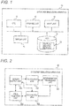
- Fig. 2 is a functional block diagram showing the functional configuration of the extruder simulation apparatus according to the embodiment.
- the extruder simulation apparatus 10 includes, as its functions, a screen output unit 101 which displays various kinds of screens on the display unit 14 and obtains setting parameters inputted therein, an 1D analysis unit 102 which executes the 1D fluid-flow analysis processing described later, a determination processing unit 103 which performs determination processings in various kinds of processings, an area selection unit 104 which receives selection of an object area of the 3D fluid-flow analysis processing described later, and a 3D analysis unit 105 which executes the 3D fluid-flow analysis processing described later.
- the functions are realized by cooperatively operating aforementioned hardware resource such as the CPU 11 and the storage unit 12 based on the coupled analysis program 20.
- Fig. 3 is a flowchart showing the 1D-3D coupled analysis processing according to the embodiment.
- the 1D-3D coupled analysis processing is triggered when the extruder simulation apparatus 10 is started and the coupled analysis program 20 is executed.
- the screen output unit 101 displays a start screen (Tex-Fan window) shown in Fig. 4 on the display unit 14 (S1).
- the screen output unit 101 displays a screw shape data preparation screen (Tex-Geo-[model, scw] window) on the display unit 14 and receives an input of screw configuration data necessary for the 1D fluid-flow analysis (S2).
- the item "New Analysis” is displayed so as to be selectable in a case that a user clicks and selects, for example, an item "File” shown in Fig. 4 .
- the screen output unit 101 displays component pieces 5a shown in Fig. 5 representing various kinds of components configuring a screw so as to be selectable by a click operation using the input unit 13. Then, a user selects the component piece by clicking the displayed component piece and drags and drops the selected component piece to the right side on the screen while maintaining the clicked state, so that various kinds of the component pieces 5a are coupled and the screw shape data 5b is displayed.
- a property window 5c of the respective dropped component piece is displayed to allow input of the configuration data.
- an L/D, a lead, an angle, an outer diameter, a flight position, a marking number, screw material, spear, an end face deviation angle, and so on are inputted as the configuration data.
- a cylinder diameter and a groove depth, etc. may also be inputted depending on the screw shape, that is, the component piece 5a to be selected.
- the technique of preparing the screw shape data is not limited to this technique but an optional known technique capable of preparing a screw shape may be employed. However, in view of a step of selecting an object area of the 3D fluid-flow analysis processing described later, it is preferable to employ a technique which enables a user to prepare visually recognizable and selectable screw shape data.
- the screen output unit 101 displays "Analysis Wizard” as another window.
- the screen output unit displays, in this analysis wizard, for example, a not-shown input screen of viscosity data of resin material, a display screen of a viscosity prediction curve as shown in Fig. 6 , a setting screen of resin physical property data as shown in Fig. 7 , and then receives inputs of various kinds of resin physical property data necessary for the 1D fluid-flow analysis (S3).
- the viscosity data to be inputted is, for example, shear viscosity data at shear rates of at least three kinds or more at each level, that is measured in advance under a temperature condition of at least two levels.
- a cross model is selected as the viscosity model formula. Further, in this embodiment, in the setting screen shown in Fig.
- a solid density, a solid thermal conductivity, a solid specific heat, a melt density, a melt thermal conductivity, a melt specific heat, a melting heat quantity, a melting point, and so on are inputted as the resin physical property data.
- the input screen of viscosity data, the display screen and the setting screen are sequentially shifted in response to selection of a "Next" button provided in the "Analysis Wizard".
- the current window is closed.
- "Return" the display returns to the most-recent various kinds of screens.
- the screen output unit 101 displays a setting screen of operation conditions (analysis conditions) in an "Analysis Wizard” window, and receives inputs of various kinds of operation conditions necessary for the 1D fluid-flow analysis processing (S4).
- operation conditions an extruder type, an extrusion quantity, a screw rotation speed, a screw tip pressure, a raw resin temperature and cylinder temperatures at respective important portions of the screw are inputted. Further, as shown in Fig.
- the screen output unit 101 displays a confirmation screen of the various kinds of setting parameters having been set in the "Analysis Wizard” window, thus urging a user to confirm the parameters (S5).
- the screen output unit 101 closes the "Analysis Wizard” window, and the 1D fluid-flow analysis processing is executed by the 1D analysis unit 102 and the determination processing unit 103 (S6).
- the 1D fluid-flow analysis processing is executed based on the various kinds of setting parameters.
- a display screen (Tex-Fan-[Result, fan]) showing analysis results of the 1D fluid-flow analysis processing is displayed as shown in Fig. 10 .
- Residence Time, Fill Factor, Temp (raw resin temperature), Pressure (resin pressure) are outputted as the results of the 1D fluid-flow analysis processing.
- the screen output unit 101 displays a "Confirmation” window containing "Yes” and “No” buttons as another window, and further displays a presentation screen asking whether or not the processing proceeds to the 3D fluid-flow analysis processing, thus urging a user to select whether or not the 3D fluid-flow analysis processing is to be executed (S7).
- this "Confirmation” window is displayed in a state that the display screen of the analysis results of the 1D fluid-flow analysis processing is displayed.
- scales and display magnifications of the respective graphs can be changed freely.
- the processing proceeds to the configuration data receiving processing of step S2 in order to execute the 1D fluid-flow analysis processing again.
- the "Confirmation" window may be closed while keeping the display of the display screen of the analysis results of the 1D fluid-flow analysis processing.
- the area selection unit 104 enables selection of an object area of the 3D fluid-flow analysis on the screw shape data 5b displayed on the display screen of the analysis results of the 1D fluid-flow analysis processing, and further enables execution of the 3D fluid-flow analysis processing in response to this selection, thus urging a user to perform this selection and the execution (S8).
- the 3D fluid-flow analysis object area is an area representing the arithmetic object field of the 3D fluid-flow analysis processing. This area is shown by a symbol 12a in Fig. 12 .
- the 3D analysis unit 105 executes the 3D fluid-flow analysis processing (S9), thus completing this flowchart.
- the 3D fluid-flow analysis processing is executed based on the various kinds of setting parameters used in the 1D fluid-flow analysis processing and the analysis results of 1D fluid-flow analysis processing.
- a window displaying new analysis results of the 3D fluid-flow analysis processing is displayed.
- This window can display, as 3D shapes, for example, element division data in an entirety of the flow path shown in Fig. 13 , element division data of the screw shape shown in Fig. 14 , pressure distribution data shown on a right lower side in a screen of Fig. 15 , and resin temperature distribution data.
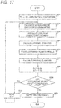
- Fig. 17 is a flowchart showing the 1D fluid-flow analysis processing.
- S603 extrusion characteristic formula
- Fig. 18 is flowchart showing the 3D fluid-flow analysis processing.
- the 3D analysis unit 105 obtains the various kinds of the setting parameters like the 1D fluid-flow analysis processing and sets as analysis condition parameters (S901). Further, the 3D analysis unit extracts and sets boundary condition data from the analysis results of the 1D fluid-flow analysis processing (S902).
- the boundary condition data is a resin material temperature T of a boundary position located at an upstream side end portion of the 3D fluid-flow analysis object area 12a and a resin material pressure P of a boundary position located at a downstream side end portion of this area.
- the analysis results of the 1D fluid-flow analysis processing is outputted as the average values at respective cross-sections.
- the pressure P and the velocity v can be obtained as a solution by solving a simultaneous equation of the four expressions (1) to (4).
- expressions for obtaining the physical quantities are not limited to the expressions but may be optional ones so long as they can obtain physical quantities of the respective calculation points.
- the determination processing unit 103 determines whether or not each of the pressure differences ⁇ P and the temperature differences ⁇ T are lower than respective predetermined convergence values (S908). In a case that the pressure difference ⁇ P and the temperature difference ⁇ T are determined to be lower than the predetermined convergence values, respectively (S908, Yes), the image output unit outputs the analysis results. For example, the image output unit outputs and displays the pressure P, as the physical quantity, in the form of a graph as shown on the upper right side in the screen of Fig. 15 and also in the form of pressure distribution image of 3D format on the lower right side as shown in this screen (S909), thus completing this flowchart.
- the 1D fluid-flow analysis processing and the 3D fluid-flow analysis processing may be executed serially (the 3D fluid-flow analysis processing may be executed automatically after completion of the 1D fluid-flow analysis processing) by setting the 3D fluid-flow analysis object area 12a in advance before executing the 1D fluid-flow analysis processing.
- Fig. 19 is a flowchart showing the second 1D-3D coupled analysis processing in which the 1D fluid-flow analysis processing and the 3D fluid-flow analysis processing is executed serially.
- processings identical to those shown in Fig. 3 are referred to by the common symbols, with explanation thereof being omitted.
- the selection processing of the 3D fluid-flow analysis object area 12a in step S8 is performed after the configuration data input receiving processing of step S2. Thereafter, the resin physical property data input receiving processing of step S3 is executed.
- both the 1D fluid-flow analysis results and the 3D fluid-flow analysis results is outputted (displayed) simultaneously as shown in Fig. 14 .
- the setting item necessary for executing the 3D fluid-flow analysis processing is only the selection and extraction of the 3D fluid-flow analysis object area 12a based on the entire screw configuration of the extruder set before the execution of the 1D fluid-flow analysis processing.
- the analysis condition parameters are shared between the 1D and 3D fluid-flow analysis processing and the boundary condition data necessary for the 3D fluid-flow analysis processing is automatically extracted from the analysis results of the 1D fluid-flow analysis processing.
- a command for making a user select one of the 1D-3D coupled analysis processing shown in Fig. 3 and the second 1D-3D coupled analysis processing shown in Fig. 19 , may be set, for example, on the start screen.
- an arithmetic operation according to an object of the coupled analysis can be selectively executed.
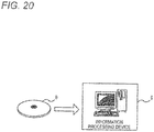
- the coupled analysis program 20 described in the embodiment may be stored in a portable storage medium 8 readable by a computer, as shown in Fig. 20 .
- an information processing device 9 can realize the functions described above by reading the storage medium 8.
- an icon for starting this program is displayed on the display unit 14. Then, if a user selects this icon, the start screen as shown in Fig. 4 is displayed.
- the storage medium 8 may be an optional medium readable by a computer such as an optical disc (CD-ROM, DVD disc or the like), a magnetic disc (hard disc drive or the like), a flash memory, an 1C card, or a medium transmittable via a network.
- a simulation apparatus described in the claims is, for example, the extruder simulation apparatus 10 according the embodiment.
- a simulation method described in the claims is, for example, the 1D-3D coupled analysis processing.
- a simulation program is, for example, the coupled analysis program 20.
- a low-dimensional analysis unit is, for example, the 1D analysis unit 102 and the determination processing unit 103.
- a selection receiving unit is, for example, the area selection unit 104.
- a physical quantity extraction unit is, for example, the 3D analysis unit 105.
- a high-dimensional analysis unit is, for example, the determination processing unit 103 and the 3D analysis unit 105.
- a data display unit and a display device are, for example, the screen output unit 101 and the display unit 14, respectively.
- a slide bar is, for example, the slide bar 15a.
Landscapes
- Engineering & Computer Science (AREA)
- Mechanical Engineering (AREA)
- Mathematical Optimization (AREA)
- Algebra (AREA)
- General Physics & Mathematics (AREA)
- Mathematical Analysis (AREA)
- Physics & Mathematics (AREA)
- Mathematical Physics (AREA)
- Pure & Applied Mathematics (AREA)
- Manufacturing & Machinery (AREA)
- Extrusion Moulding Of Plastics Or The Like (AREA)
- Injection Moulding Of Plastics Or The Like (AREA)
- Management, Administration, Business Operations System, And Electronic Commerce (AREA)
Claims (7)
- Simulationsvorrichtung zur Ausführung einer Fluidströmungsanalyse von Material, mit:einer niedrigdimensionalen Auswerteeinheit, die ausgebildet ist, eine niedrigdimensionale Fluidströmungsauswertung des Materials in einem arithmetischen Objektfeld einer Knetvorrichtung auf der Grundlage einer Einstellungsinformation auszuführen, wobei die Einstellungsinformation beinhaltet:eine physikalische Eigenschaft des Materials; undKonfigurationsdaten und Betriebsbedingungen der Knetvorrichtung für das Kneten des Materials;einer Auswahlempfangseinheit, die ausgebildet ist, nach oder vor der niedrigdimensionalen Fluidströmungsauswertung eine Auswahl eines Objektbereichs als ein Objekt einer hochdimensionalen Fluidströmungsauswertung in dem arithmetischen Objektfeld der Knetvorrichtung zu empfangen;einer Einheit zur Extraktion einer physikalischen Größe, wobei die Einheit ausgebildet ist, physikalische Größen des Materials in Bezug auf den Objektbereich auf der Grundlage eines Ergebnisses der niedrigdimensionalen Fluidströmungsauswertung des Materials in dem arithmetischen Objektfeld der Knetvorrichtung zu extrahieren; undeiner hochdimensionalen Auswerteeinheit, die ausgebildet ist, eine hochdimensionale Fluidströmungsauswertung des Materials in dem Objektbereich in dem arithmetischen Objektfeld der Knetvorrichtung auf der Grundlage der extrahierten physikalischen Größe des Materials bezüglich des Objektbereichs und auf der Grundlage der Einstellinformation auszuführen.
- Simulationsvorrichtung nach Anspruch 1,
wobei die niedrigdimensionale Auswerteeinheit mindestens eine Temperatur und einen Druck des Materials als Auswerteergebnis berechnet, und
wobei die physikalischen Größen des Materials bezüglich des ausgewählten Objektbereichs eine Temperatur des Materials an einer Grenzlage, die auf einem in Strömungsrichtung vorgeordneten Endbereich des Objektbereichs liegt, und ein Druck des Materials an einer Grenzlage, die an einer in Strömungsrichtung nachgeordneten Seite des Endbereichs des Objektbereichs liegt, sind. - Simulationsvorrichtung nach Anspruch 1 oder 2,
wobei die niedrigdimensionale Auswertung eine eindimensionale Auswertung unter Anwendung eines FAN-Verfahrens ist, und
wobei die hochdimensionale Auswertung eine dreidimensionale Auswertung unter Anwendung eines Gitterelementeverfahrens ist. - Simulationsvorrichtung nach einem der Ansprüche 1 bis 3, die ferner aufweist:eine Datenanzeigeeinheit, die ausgebildet ist, auf einer Anzeigeeinrichtung Formdaten anzuzeigen, die eine Schraubenform in Bezug auf das arithmetische Objektfeld zeigen,wobei die Auswahlempfangseinheit einen Bereich, der aus den auf der Anzeigeeinrichtung angezeigten Formdaten ausgewählt ist, als den Objektbereich ermittelt.
- Simulationsvorrichtung nach Anspruch 4,
wobei die Datenanzeigeeinheit auf der Anzeigeeinrichtung eine Balkenanzeige anzeigt, die auf den Formdaten entsprechend der Betätigung eines Benutzers derart verschiebbar ist, dass ein Auswerteergebnis der niedrigdimensionalen Fluidströmungsauswertung eines Querschnitts in dem arithmetischen Objektfeld zugeordnet zu einer Position, an der die Balkenanzeige angeordnet ist, entsprechend dem Auswerteergebnis der hochdimensionalen Fluidströmungsauswertung angezeigt wird. - Simulationsverfahren, das von einer Simulationsvorrichtung zum Ausführen einer Fluidströmungsanalyse von Material ausgeführt wird, wobei das Verfahren umfasst:Ausführen einer niedrigdimensionalen Fluidströmungsauswertung des Materials in einem arithmetischen Objektfeld einer Knetvorrichtung auf der Grundlage einer Einstellungsinformation, wobei die Einstellungsinformation beinhaltet:eine physikalische Eigenschaft des Materials; undKonfigurationsdaten und eine Betriebsbedingung der Knetvorrichtung zum Kneten des Materials;nach oder vor der niedrigdimensionalen Fluidströmungsauswertung, Empfangen einer Auswahl für einen Objektbereich als ein Objekt einer hochdimensionalen Fluidströmungsauswertung in dem arithmetischen Objektfeld der Knetvorrichtung;Extrahieren von physikalischen Größen des Materials bezüglich des Objektbereichs auf der Grundlage eines Ergebnisses der niedrigdimensionalen Fluidströmungsauswertung des Materials in dem arithmetischen Objektfeld der Knetvorrichtung; undAusführen einer hochdimensionalen Fluidströmungsauswertung des Materials in dem Objektbereich in dem arithmetischen Objektfeld der Knetvorrichtung auf der Grundlage der extrahierten physikalischen Größen des Materials bezüglich des Objektbereichs und auf der Grundlage der Einstellungsinformation.
- Simulationsprogramm zum Ausführen einer Fluidströmungsanalyse von Material, wobei das Simulationsprogramm bewirkt, dass ein Computer agiert als:eine niedrigdimensionale Auswerteeinheit, die ausgebildet ist, eine niedrigdimensionale Fluidströmungsauswertung des Materials in einem arithmetischen Objektfeld einer Knetvorrichtung auf der Grundlage einer Einstellungsinformation auszuführen, wobei die Einstellungsinformation beinhaltet:eine physikalische Eigenschaft des Materials; undKonfigurationsdaten und Betriebsbedingungen der Knetvorrichtung für das Kneten des Materials;eine Auswahlempfangseinheit, die ausgebildet ist, nach oder vor der niedrigdimensionalen Fluidströmungsauswertung eine Auswahl eines Objektbereichs als ein Objekt einer hochdimensionalen Fluidströmungsauswertung in dem arithmetischen Objektfeld der Knetvorrichtung zu empfangen;eine Einheit zur Extraktion einer physikalischen Größe, wobei die Einheit ausgebildet ist,physikalische Größen des Materials in Bezug auf den Objektbereich auf der Grundlage eines Ergebnisses der niedrigdimensionalen Fluidströmungsauswertung des Materials in dem arithmetischen Objektfeld der Knetvorrichtung zu extrahieren; undeine hochdimensionale Auswerteeinheit, die ausgebildet ist, eine hochdimensionale Fluidströmungsauswertung des Materials in dem Objektbereich in dem arithmetischen Objektfeld der Knetvorrichtung auf der Grundlage der extrahierten physikalischen Größe des Materials bezüglich des Objektbereichs und auf der Grundlage der Einstellinformation auszuführen.
Applications Claiming Priority (1)
| Application Number | Priority Date | Filing Date | Title |
|---|---|---|---|
| JP2014229018A JP6047136B2 (ja) | 2014-11-11 | 2014-11-11 | シミュレーション装置、そのシミュレーション方法及びシミュレーションプログラム |
Publications (2)
| Publication Number | Publication Date |
|---|---|
| EP3020530A1 EP3020530A1 (de) | 2016-05-18 |
| EP3020530B1 true EP3020530B1 (de) | 2021-08-11 |
Family
ID=55027223
Family Applications (1)
| Application Number | Title | Priority Date | Filing Date |
|---|---|---|---|
| EP15194031.9A Active EP3020530B1 (de) | 2014-11-11 | 2015-11-11 | Simulationsvorrichtung, simulationsverfahren und simulationsprogramm |
Country Status (3)
| Country | Link |
|---|---|
| US (1) | US10549453B2 (de) |
| EP (1) | EP3020530B1 (de) |
| JP (1) | JP6047136B2 (de) |
Families Citing this family (8)
| Publication number | Priority date | Publication date | Assignee | Title |
|---|---|---|---|---|
| EP3640002B1 (de) * | 2017-06-13 | 2024-08-07 | The Japan Steel Works, Ltd. | Schraubenformschätzvorrichtung, schraubenformschätzverfahren und schraubformschätzprogramm |
| JP6869621B2 (ja) * | 2017-08-30 | 2021-05-12 | 住友重機械工業株式会社 | シミュレーション方法及びシミュレーション装置 |
| JP7171318B2 (ja) * | 2018-08-31 | 2022-11-15 | キヤノン株式会社 | 情報処理装置、情報処理方法及びプログラム |
| EP4066144A1 (de) * | 2019-11-26 | 2022-10-05 | Basf Se | Optimierung der geometrie von formkörpern und fertigungswerkzeugen |
| CN114829106A (zh) | 2019-11-28 | 2022-07-29 | 巴斯夫欧洲公司 | 用于控制聚合物粘度质量的方法与控制系统 |
| TWI837464B (zh) * | 2020-03-31 | 2024-04-01 | 日商旭化成股份有限公司 | 支援樹脂成形之裝置、方法及程式 |
| WO2024095323A1 (ja) * | 2022-10-31 | 2024-05-10 | ファナック株式会社 | 成形条件入力システム及び成形条件入力システムの制御方法 |
| JP7594056B1 (ja) * | 2023-07-20 | 2024-12-03 | 日鉄エンジニアリング株式会社 | 表示制御装置 |
Family Cites Families (14)
| Publication number | Priority date | Publication date | Assignee | Title |
|---|---|---|---|---|
| JPH03288620A (ja) | 1990-04-05 | 1991-12-18 | Sekisui Chem Co Ltd | 2軸押出機内樹脂流路の熱流動解析方法 |
| JPH04364921A (ja) * | 1991-06-13 | 1992-12-17 | Sekisui Chem Co Ltd | 押出機内樹脂流路の熱流動解析方法 |
| TW305798B (de) * | 1994-08-01 | 1997-05-21 | Toray Industries | |
| JP3712762B2 (ja) * | 1995-07-20 | 2005-11-02 | 旭化成ケミカルズ株式会社 | 押出機運転シミュレーションシステム |
| JP2001001386A (ja) * | 1999-06-17 | 2001-01-09 | Kuraray Co Ltd | 2軸押出機における樹脂の流動解析方法およびスクリュー設計方法 |
| JP2002214107A (ja) | 2001-01-18 | 2002-07-31 | Kobe Steel Ltd | 二軸混練押出機に関する情報提供システム |
| US6810333B2 (en) * | 2002-02-12 | 2004-10-26 | General Electric Company | Method, system, storage medium, and data signal for supplying a multi-component composition |
| JP3679392B2 (ja) | 2002-10-31 | 2005-08-03 | 株式会社日本製鋼所 | スクリュ式押出機のシミュレーション装置、そのシミュレーション方法及びシミュレーションプログラム |
| JP2006103316A (ja) * | 2004-09-10 | 2006-04-20 | Toyo Seiki Seisakusho:Kk | 成形加工性評価システム及びその方法 |
| JP2006164219A (ja) | 2004-11-09 | 2006-06-22 | Phifit Kk | 有限要素解析用インターフェース、有限要素解析用インターフェースのプログラムを記録したコンピュータ読み取り可能な記録媒体、高付加価値通信網を利用した有限要素解析方法、有限要素解析用並列処理計算機および有限要素解析用計算機 |
| US7731495B2 (en) * | 2005-12-20 | 2010-06-08 | 3M Innovative Properties Company | User interface having cross section control tool for digital orthodontics |
| JP4414408B2 (ja) | 2006-03-28 | 2010-02-10 | 株式会社日本製鋼所 | スクリュ式押出機の脱揮シミュレーション装置、およびスクリュ式押出機の脱揮シミュレーションプログラム |
| US8539005B2 (en) * | 2009-09-18 | 2013-09-17 | Steer Information Technologies Pvt. Ltd. | Method and system for configuring and visualizing an extruder |
| US9098106B2 (en) * | 2012-08-10 | 2015-08-04 | Comsol Ab | Systems and methods for creating application interfaces for forming and solving problems in a modeling system |
-
2014
- 2014-11-11 JP JP2014229018A patent/JP6047136B2/ja active Active
-
2015
- 2015-11-10 US US14/937,217 patent/US10549453B2/en active Active
- 2015-11-11 EP EP15194031.9A patent/EP3020530B1/de active Active
Non-Patent Citations (1)
| Title |
|---|
| ADAM DREIBLATT: "Computer Modeling of Twin-Screw Compounding Using One-Dimensional Process Simulation", 31 December 2012 (2012-12-31), pages 1 - 56, XP055326804, Retrieved from the Internet <URL:http://www.b4uextrude.com/images/SPE_Minitec_Presentation.pdf> [retrieved on 20161207] * |
Also Published As
| Publication number | Publication date |
|---|---|
| JP2016088056A (ja) | 2016-05-23 |
| US20160132621A1 (en) | 2016-05-12 |
| JP6047136B2 (ja) | 2016-12-21 |
| US10549453B2 (en) | 2020-02-04 |
| EP3020530A1 (de) | 2016-05-18 |
Similar Documents
| Publication | Publication Date | Title |
|---|---|---|
| EP3020530B1 (de) | Simulationsvorrichtung, simulationsverfahren und simulationsprogramm | |
| JP6913166B2 (ja) | スクリュ形状推定装置、スクリュ形状推定方法、スクリュ形状推定プログラム | |
| EP4065336B1 (de) | Verfahren und steuerungssystem zur steuerung der polymerviskositätsqualität | |
| Hao et al. | Material characterisation and process development for chocolate additive layer manufacturing | |
| Wilczyński et al. | Multipurpose computer model for screw processing of plastics | |
| Serdeczny et al. | Viscoelastic simulation and optimisation of the polymer flow through the hot-end during filament-based material extrusion additive manufacturing | |
| JP4820318B2 (ja) | 樹脂成形品の設計支援装置、支援方法及び支援プログラム | |
| WO2021249897A1 (en) | Method for determining a coefficient in a thermoplastic polymer viscosity calculation | |
| JP2015123668A (ja) | 可塑化シミュレーション装置、その可塑化シミュレーション方法および可塑化シミュレーションプログラム | |
| Wang et al. | Instantaneous simulation of fluids and particles in complex microfluidic devices | |
| de Miranda et al. | Evaluation of the predictive capacity of viscosity models in polymer melt filling simulations | |
| JP6185515B2 (ja) | 可塑化シミュレーション装置、その可塑化シミュレーション方法および可塑化シミュレーションプログラム | |
| Düphans et al. | Experimental and numerical characterization of screw elements used in twin-screw extrusion | |
| JP6550347B2 (ja) | 可塑化シミュレーション装置、その可塑化シミュレーション方法および可塑化シミュレーションプログラム | |
| JP6092832B2 (ja) | 流動挙動予測装置、その流動挙動予測方法および流動挙動予測プログラム | |
| JP2005241443A (ja) | 熱的非平衡状態における高分子材料の流動物性予測方法 | |
| JP4643373B2 (ja) | 押出スクリュの均一溶融シミュレーション方法およびその方法を実行するコンピュータプログラムおよび押出スクリュの均一溶融シミュレーション装置 | |
| JP7537191B2 (ja) | 情報処理装置及び情報処理プログラム | |
| Fan et al. | An analytical non-Newtonian and nonisothermal viscous flow simulation | |
| US20200384674A1 (en) | System and method for setting molding conditions of injection -molding equipment | |
| Meng et al. | Two-relaxation-time lattice Boltzmann model of the velocity profiles and volumetric flow rate of generalized Newtonian fluids in a single-screw extruder | |
| Nabialek et al. | The influence of input data on the results of injection molding process simulation | |
| JP6029559B2 (ja) | コンピュータ支援による金型設計装置 | |
| Pourhosseinian et al. | Starve Feeding in Screw Extruders: A Review | |
| JP2014104696A (ja) | 演算プログラム及び演算方法 |
Legal Events
| Date | Code | Title | Description |
|---|---|---|---|
| PUAI | Public reference made under article 153(3) epc to a published international application that has entered the european phase |
Free format text: ORIGINAL CODE: 0009012 |
|
| AK | Designated contracting states |
Kind code of ref document: A1 Designated state(s): AL AT BE BG CH CY CZ DE DK EE ES FI FR GB GR HR HU IE IS IT LI LT LU LV MC MK MT NL NO PL PT RO RS SE SI SK SM TR |
|
| AX | Request for extension of the european patent |
Extension state: BA ME |
|
| STAA | Information on the status of an ep patent application or granted ep patent |
Free format text: STATUS: REQUEST FOR EXAMINATION WAS MADE |
|
| 17P | Request for examination filed |
Effective date: 20161118 |
|
| RBV | Designated contracting states (corrected) |
Designated state(s): AL AT BE BG CH CY CZ DE DK EE ES FI FR GB GR HR HU IE IS IT LI LT LU LV MC MK MT NL NO PL PT RO RS SE SI SK SM TR |
|
| STAA | Information on the status of an ep patent application or granted ep patent |
Free format text: STATUS: EXAMINATION IS IN PROGRESS |
|
| 17Q | First examination report despatched |
Effective date: 20191106 |
|
| REG | Reference to a national code |
Ref country code: DE Ref legal event code: R079 Ref document number: 602015072137 Country of ref document: DE Free format text: PREVIOUS MAIN CLASS: B29C0047080000 Ipc: B29C0048920000 |
|
| GRAP | Despatch of communication of intention to grant a patent |
Free format text: ORIGINAL CODE: EPIDOSNIGR1 |
|
| STAA | Information on the status of an ep patent application or granted ep patent |
Free format text: STATUS: GRANT OF PATENT IS INTENDED |
|
| RIC1 | Information provided on ipc code assigned before grant |
Ipc: G06F 9/44 20180101ALN20210217BHEP Ipc: B29C 48/92 20190101AFI20210217BHEP Ipc: B29C 48/40 20190101ALI20210217BHEP Ipc: B29C 48/25 20190101ALI20210217BHEP Ipc: G01N 11/04 20060101ALN20210217BHEP Ipc: B29B 7/48 20060101ALN20210217BHEP |
|
| INTG | Intention to grant announced |
Effective date: 20210309 |
|
| GRAS | Grant fee paid |
Free format text: ORIGINAL CODE: EPIDOSNIGR3 |
|
| GRAA | (expected) grant |
Free format text: ORIGINAL CODE: 0009210 |
|
| STAA | Information on the status of an ep patent application or granted ep patent |
Free format text: STATUS: THE PATENT HAS BEEN GRANTED |
|
| AK | Designated contracting states |
Kind code of ref document: B1 Designated state(s): AL AT BE BG CH CY CZ DE DK EE ES FI FR GB GR HR HU IE IS IT LI LT LU LV MC MK MT NL NO PL PT RO RS SE SI SK SM TR |
|
| REG | Reference to a national code |
Ref country code: CH Ref legal event code: EP |
|
| REG | Reference to a national code |
Ref country code: DE Ref legal event code: R096 Ref document number: 602015072137 Country of ref document: DE |
|
| REG | Reference to a national code |
Ref country code: IE Ref legal event code: FG4D Ref country code: AT Ref legal event code: REF Ref document number: 1418929 Country of ref document: AT Kind code of ref document: T Effective date: 20210915 |
|
| REG | Reference to a national code |
Ref country code: LT Ref legal event code: MG9D |
|
| REG | Reference to a national code |
Ref country code: NL Ref legal event code: MP Effective date: 20210811 |
|
| REG | Reference to a national code |
Ref country code: AT Ref legal event code: MK05 Ref document number: 1418929 Country of ref document: AT Kind code of ref document: T Effective date: 20210811 |
|
| PG25 | Lapsed in a contracting state [announced via postgrant information from national office to epo] |
Ref country code: SE Free format text: LAPSE BECAUSE OF FAILURE TO SUBMIT A TRANSLATION OF THE DESCRIPTION OR TO PAY THE FEE WITHIN THE PRESCRIBED TIME-LIMIT Effective date: 20210811 Ref country code: RS Free format text: LAPSE BECAUSE OF FAILURE TO SUBMIT A TRANSLATION OF THE DESCRIPTION OR TO PAY THE FEE WITHIN THE PRESCRIBED TIME-LIMIT Effective date: 20210811 Ref country code: HR Free format text: LAPSE BECAUSE OF FAILURE TO SUBMIT A TRANSLATION OF THE DESCRIPTION OR TO PAY THE FEE WITHIN THE PRESCRIBED TIME-LIMIT Effective date: 20210811 Ref country code: LT Free format text: LAPSE BECAUSE OF FAILURE TO SUBMIT A TRANSLATION OF THE DESCRIPTION OR TO PAY THE FEE WITHIN THE PRESCRIBED TIME-LIMIT Effective date: 20210811 Ref country code: AT Free format text: LAPSE BECAUSE OF FAILURE TO SUBMIT A TRANSLATION OF THE DESCRIPTION OR TO PAY THE FEE WITHIN THE PRESCRIBED TIME-LIMIT Effective date: 20210811 Ref country code: BG Free format text: LAPSE BECAUSE OF FAILURE TO SUBMIT A TRANSLATION OF THE DESCRIPTION OR TO PAY THE FEE WITHIN THE PRESCRIBED TIME-LIMIT Effective date: 20211111 Ref country code: ES Free format text: LAPSE BECAUSE OF FAILURE TO SUBMIT A TRANSLATION OF THE DESCRIPTION OR TO PAY THE FEE WITHIN THE PRESCRIBED TIME-LIMIT Effective date: 20210811 Ref country code: FI Free format text: LAPSE BECAUSE OF FAILURE TO SUBMIT A TRANSLATION OF THE DESCRIPTION OR TO PAY THE FEE WITHIN THE PRESCRIBED TIME-LIMIT Effective date: 20210811 Ref country code: NO Free format text: LAPSE BECAUSE OF FAILURE TO SUBMIT A TRANSLATION OF THE DESCRIPTION OR TO PAY THE FEE WITHIN THE PRESCRIBED TIME-LIMIT Effective date: 20211111 Ref country code: PT Free format text: LAPSE BECAUSE OF FAILURE TO SUBMIT A TRANSLATION OF THE DESCRIPTION OR TO PAY THE FEE WITHIN THE PRESCRIBED TIME-LIMIT Effective date: 20211213 |
|
| PG25 | Lapsed in a contracting state [announced via postgrant information from national office to epo] |
Ref country code: PL Free format text: LAPSE BECAUSE OF FAILURE TO SUBMIT A TRANSLATION OF THE DESCRIPTION OR TO PAY THE FEE WITHIN THE PRESCRIBED TIME-LIMIT Effective date: 20210811 Ref country code: LV Free format text: LAPSE BECAUSE OF FAILURE TO SUBMIT A TRANSLATION OF THE DESCRIPTION OR TO PAY THE FEE WITHIN THE PRESCRIBED TIME-LIMIT Effective date: 20210811 Ref country code: GR Free format text: LAPSE BECAUSE OF FAILURE TO SUBMIT A TRANSLATION OF THE DESCRIPTION OR TO PAY THE FEE WITHIN THE PRESCRIBED TIME-LIMIT Effective date: 20211112 |
|
| PG25 | Lapsed in a contracting state [announced via postgrant information from national office to epo] |
Ref country code: NL Free format text: LAPSE BECAUSE OF FAILURE TO SUBMIT A TRANSLATION OF THE DESCRIPTION OR TO PAY THE FEE WITHIN THE PRESCRIBED TIME-LIMIT Effective date: 20210811 |
|
| PG25 | Lapsed in a contracting state [announced via postgrant information from national office to epo] |
Ref country code: DK Free format text: LAPSE BECAUSE OF FAILURE TO SUBMIT A TRANSLATION OF THE DESCRIPTION OR TO PAY THE FEE WITHIN THE PRESCRIBED TIME-LIMIT Effective date: 20210811 |
|
| REG | Reference to a national code |
Ref country code: DE Ref legal event code: R097 Ref document number: 602015072137 Country of ref document: DE |
|
| PG25 | Lapsed in a contracting state [announced via postgrant information from national office to epo] |
Ref country code: SM Free format text: LAPSE BECAUSE OF FAILURE TO SUBMIT A TRANSLATION OF THE DESCRIPTION OR TO PAY THE FEE WITHIN THE PRESCRIBED TIME-LIMIT Effective date: 20210811 Ref country code: SK Free format text: LAPSE BECAUSE OF FAILURE TO SUBMIT A TRANSLATION OF THE DESCRIPTION OR TO PAY THE FEE WITHIN THE PRESCRIBED TIME-LIMIT Effective date: 20210811 Ref country code: RO Free format text: LAPSE BECAUSE OF FAILURE TO SUBMIT A TRANSLATION OF THE DESCRIPTION OR TO PAY THE FEE WITHIN THE PRESCRIBED TIME-LIMIT Effective date: 20210811 Ref country code: EE Free format text: LAPSE BECAUSE OF FAILURE TO SUBMIT A TRANSLATION OF THE DESCRIPTION OR TO PAY THE FEE WITHIN THE PRESCRIBED TIME-LIMIT Effective date: 20210811 Ref country code: CZ Free format text: LAPSE BECAUSE OF FAILURE TO SUBMIT A TRANSLATION OF THE DESCRIPTION OR TO PAY THE FEE WITHIN THE PRESCRIBED TIME-LIMIT Effective date: 20210811 Ref country code: AL Free format text: LAPSE BECAUSE OF FAILURE TO SUBMIT A TRANSLATION OF THE DESCRIPTION OR TO PAY THE FEE WITHIN THE PRESCRIBED TIME-LIMIT Effective date: 20210811 |
|
| PLBE | No opposition filed within time limit |
Free format text: ORIGINAL CODE: 0009261 |
|
| STAA | Information on the status of an ep patent application or granted ep patent |
Free format text: STATUS: NO OPPOSITION FILED WITHIN TIME LIMIT |
|
| PG25 | Lapsed in a contracting state [announced via postgrant information from national office to epo] |
Ref country code: MC Free format text: LAPSE BECAUSE OF FAILURE TO SUBMIT A TRANSLATION OF THE DESCRIPTION OR TO PAY THE FEE WITHIN THE PRESCRIBED TIME-LIMIT Effective date: 20210811 |
|
| REG | Reference to a national code |
Ref country code: CH Ref legal event code: PL |
|
| 26N | No opposition filed |
Effective date: 20220512 |
|
| GBPC | Gb: european patent ceased through non-payment of renewal fee |
Effective date: 20211111 |
|
| PG25 | Lapsed in a contracting state [announced via postgrant information from national office to epo] |
Ref country code: LU Free format text: LAPSE BECAUSE OF NON-PAYMENT OF DUE FEES Effective date: 20211111 Ref country code: BE Free format text: LAPSE BECAUSE OF NON-PAYMENT OF DUE FEES Effective date: 20211130 |
|
| REG | Reference to a national code |
Ref country code: BE Ref legal event code: MM Effective date: 20211130 |
|
| PG25 | Lapsed in a contracting state [announced via postgrant information from national office to epo] |
Ref country code: SI Free format text: LAPSE BECAUSE OF FAILURE TO SUBMIT A TRANSLATION OF THE DESCRIPTION OR TO PAY THE FEE WITHIN THE PRESCRIBED TIME-LIMIT Effective date: 20210811 |
|
| PG25 | Lapsed in a contracting state [announced via postgrant information from national office to epo] |
Ref country code: IE Free format text: LAPSE BECAUSE OF NON-PAYMENT OF DUE FEES Effective date: 20211111 Ref country code: GB Free format text: LAPSE BECAUSE OF NON-PAYMENT OF DUE FEES Effective date: 20211111 |
|
| PG25 | Lapsed in a contracting state [announced via postgrant information from national office to epo] |
Ref country code: HU Free format text: LAPSE BECAUSE OF FAILURE TO SUBMIT A TRANSLATION OF THE DESCRIPTION OR TO PAY THE FEE WITHIN THE PRESCRIBED TIME-LIMIT; INVALID AB INITIO Effective date: 20151111 |
|
| P01 | Opt-out of the competence of the unified patent court (upc) registered |
Effective date: 20230515 |
|
| PG25 | Lapsed in a contracting state [announced via postgrant information from national office to epo] |
Ref country code: CY Free format text: LAPSE BECAUSE OF FAILURE TO SUBMIT A TRANSLATION OF THE DESCRIPTION OR TO PAY THE FEE WITHIN THE PRESCRIBED TIME-LIMIT Effective date: 20210811 |
|
| PG25 | Lapsed in a contracting state [announced via postgrant information from national office to epo] |
Ref country code: LI Free format text: LAPSE BECAUSE OF NON-PAYMENT OF DUE FEES Effective date: 20220701 Ref country code: CH Free format text: LAPSE BECAUSE OF NON-PAYMENT OF DUE FEES Effective date: 20220701 |
|
| PG25 | Lapsed in a contracting state [announced via postgrant information from national office to epo] |
Ref country code: MK Free format text: LAPSE BECAUSE OF FAILURE TO SUBMIT A TRANSLATION OF THE DESCRIPTION OR TO PAY THE FEE WITHIN THE PRESCRIBED TIME-LIMIT Effective date: 20210811 |
|
| PG25 | Lapsed in a contracting state [announced via postgrant information from national office to epo] |
Ref country code: MT Free format text: LAPSE BECAUSE OF FAILURE TO SUBMIT A TRANSLATION OF THE DESCRIPTION OR TO PAY THE FEE WITHIN THE PRESCRIBED TIME-LIMIT Effective date: 20210811 |
|
| PGFP | Annual fee paid to national office [announced via postgrant information from national office to epo] |
Ref country code: FR Payment date: 20250930 Year of fee payment: 11 |
|
| PG25 | Lapsed in a contracting state [announced via postgrant information from national office to epo] |
Ref country code: TR Free format text: LAPSE BECAUSE OF FAILURE TO SUBMIT A TRANSLATION OF THE DESCRIPTION OR TO PAY THE FEE WITHIN THE PRESCRIBED TIME-LIMIT Effective date: 20210811 |
|
| PGFP | Annual fee paid to national office [announced via postgrant information from national office to epo] |
Ref country code: DE Payment date: 20250930 Year of fee payment: 11 |
|
| PGFP | Annual fee paid to national office [announced via postgrant information from national office to epo] |
Ref country code: IT Payment date: 20251022 Year of fee payment: 11 |