EP3020526B1 - Concrete roller head - Google Patents
Concrete roller head Download PDFInfo
- Publication number
- EP3020526B1 EP3020526B1 EP15200837.1A EP15200837A EP3020526B1 EP 3020526 B1 EP3020526 B1 EP 3020526B1 EP 15200837 A EP15200837 A EP 15200837A EP 3020526 B1 EP3020526 B1 EP 3020526B1
- Authority
- EP
- European Patent Office
- Prior art keywords
- rollers
- concrete
- extruder head
- head assembly
- troweling
- Prior art date
- Legal status (The legal status is an assumption and is not a legal conclusion. Google has not performed a legal analysis and makes no representation as to the accuracy of the status listed.)
- Active
Links
Images
Classifications
-
- B—PERFORMING OPERATIONS; TRANSPORTING
- B28—WORKING CEMENT, CLAY, OR STONE
- B28B—SHAPING CLAY OR OTHER CERAMIC COMPOSITIONS; SHAPING SLAG; SHAPING MIXTURES CONTAINING CEMENTITIOUS MATERIAL, e.g. PLASTER
- B28B11/00—Apparatus or processes for treating or working the shaped or preshaped articles
- B28B11/08—Apparatus or processes for treating or working the shaped or preshaped articles for reshaping the surface, e.g. smoothing, roughening, corrugating, making screw-threads
- B28B11/0845—Apparatus or processes for treating or working the shaped or preshaped articles for reshaping the surface, e.g. smoothing, roughening, corrugating, making screw-threads for smoothing
-
- B—PERFORMING OPERATIONS; TRANSPORTING
- B28—WORKING CEMENT, CLAY, OR STONE
- B28B—SHAPING CLAY OR OTHER CERAMIC COMPOSITIONS; SHAPING SLAG; SHAPING MIXTURES CONTAINING CEMENTITIOUS MATERIAL, e.g. PLASTER
- B28B21/00—Methods or machines specially adapted for the production of tubular articles
- B28B21/02—Methods or machines specially adapted for the production of tubular articles by casting into moulds
- B28B21/10—Methods or machines specially adapted for the production of tubular articles by casting into moulds using compacting means
- B28B21/22—Methods or machines specially adapted for the production of tubular articles by casting into moulds using compacting means using rotatable mould or core parts
- B28B21/24—Methods or machines specially adapted for the production of tubular articles by casting into moulds using compacting means using rotatable mould or core parts using compacting heads, rollers, or the like
- B28B21/247—Methods or machines specially adapted for the production of tubular articles by casting into moulds using compacting means using rotatable mould or core parts using compacting heads, rollers, or the like the rollers of the compaction head being driven, e.g. to overcome or modify the tangential force
-
- B—PERFORMING OPERATIONS; TRANSPORTING
- B28—WORKING CEMENT, CLAY, OR STONE
- B28B—SHAPING CLAY OR OTHER CERAMIC COMPOSITIONS; SHAPING SLAG; SHAPING MIXTURES CONTAINING CEMENTITIOUS MATERIAL, e.g. PLASTER
- B28B21/00—Methods or machines specially adapted for the production of tubular articles
- B28B21/02—Methods or machines specially adapted for the production of tubular articles by casting into moulds
- B28B21/10—Methods or machines specially adapted for the production of tubular articles by casting into moulds using compacting means
- B28B21/22—Methods or machines specially adapted for the production of tubular articles by casting into moulds using compacting means using rotatable mould or core parts
- B28B21/24—Methods or machines specially adapted for the production of tubular articles by casting into moulds using compacting means using rotatable mould or core parts using compacting heads, rollers, or the like
- B28B21/26—Methods or machines specially adapted for the production of tubular articles by casting into moulds using compacting means using rotatable mould or core parts using compacting heads, rollers, or the like with a packer head serving as a sliding mould or provided with guiding means for feeding the material
-
- B—PERFORMING OPERATIONS; TRANSPORTING
- B28—WORKING CEMENT, CLAY, OR STONE
- B28B—SHAPING CLAY OR OTHER CERAMIC COMPOSITIONS; SHAPING SLAG; SHAPING MIXTURES CONTAINING CEMENTITIOUS MATERIAL, e.g. PLASTER
- B28B21/00—Methods or machines specially adapted for the production of tubular articles
- B28B21/92—Methods or apparatus for treating or reshaping
- B28B21/96—Methods or apparatus for treating or reshaping for smoothing, roughening, corrugating or for removing burr
Definitions
- This invention relates generally to the field of concrete pipe manufacturing machinery, and more specifically to the packerhead system of manufacturing concrete pipe.
- Extruder head assemblies for a concrete pipe manufacturing machines are for example known from US 4 407 648 A and from US 5 080 571 A . It is conventional practice in dry casting of concrete pipe products to dispose a mold on the base of a concrete pipe machine that is provided with a vertically movable crosshead having a vertically driven shaft on the lower end of which a packer head is attached.
- the packer head typically includes a troweling cylinder that is rotated in one direction by the driven shaft, and a plurality of distributing rollers that are frictionally driven by engagement with the concrete in a direction opposite to that of the driven shaft on the troweling cylinder.
- the invention provides an extruder head assembly for a concrete pipe manufacturing machine in accordance with claim 1, wherein the troweling cylinder comprises a plurality of removable sections. Each section is composed of a plurality of removable and replaceable tile segments. When a tile segment breaks, the section containing the broken tile segment can be removed so that the broken tile segment can be replaced.
- a pipe manufacturing apparatus includes a turntable adapted to support a pallet and a cylindrical jacket or mold having a cylindrical reinforcing cage used in the formation of a tubular concrete pipe.
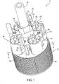
- An upper portion of the pipe manufacturing apparatus supports a downwardly directed drive shaft 24 to which the extruder head assembly 12 is mounted for simultaneous movement therewith vertically inside the mold.
- Drive shaft 24 is conventionally driven by a motor drive system mounted on the upper portion of the pipe manufacturing apparatus to provide rotational movement as well as vertical movement to the drive shaft 24 and the extruder head assembly 12.
- a pipe making apparatus has a top table with a funneling mouth located above the upper end of the jacket for receiving a stream or flow of concrete as delivered from a feeding device such as a conveyor, which directs the concrete through the funneling mouth and into the jacket above the extruder head assembly 12.
- the extruder head assembly 12 has a troweling cylinder assembly 34 and a plurality of roller assemblies 36.
- Troweling cylinder assembly 34 includes a circular head plate 38. Connected centrally to the head plate 38 is an upstanding cylindrical hub 48 having a lower circular flange 50, which is secured by bolts 52 to a mating second circular flange 54 joined to the bottom end of drive shaft 24.
- the hub 48 and flanges 50, 54 are suitably dimensioned to allow the extruder head assembly 12 to adequately handle the rotational and vertical forces applied through the drive shaft 24.
- Roller assemblies 36 include a plurality of elliptical or non-round rollers 56 for rotation relative to the head plate 38 of troweling cylinder assembly 34.
- rollers 56 are rotated by frictional contact with the wet concrete mixture in a direction counter to the direction of rotation of drive shaft 24 and troweling cylinder assembly 34 connected thereto.
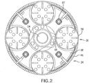
- a set of four rollers 56 are spaced about the periphery of head plate 38 to compact the concrete mixture delivered into the jacket.
- the outermost surface of rollers 56 is preferably in intermittent vertical alignment with an outer troweling surface 44 of the troweling cylinder, as seen in Fig. 2 .
- One skilled in the art would recognize any number of rollers 56 could be used, but an even number of rollers 56 evenly spaced around the periphery balances the weight and equalizes the lateral forces on the drive shaft to minimize vibration.
- Fig. 2 shows a cross-section of extruder head assembly 12 looking down on roller assemblies 36.
- each roller 56 is oblong or somewhat oval in configuration.
- the non-round rollers 56 rotate against the inside surface of the wet concrete mixture to compact the concrete mixture in the jacket.
- the rotation of non-round rollers 56 causes an oscillating impacting force against the inside surface of the concrete pipe to increase compaction of the concrete similar to a repeated paddling by rollers 56 against the wet concrete mixture.
- Compaction of the concrete mixture expels entrapped air and packs the aggregate particles together to increase the density of the concrete mixture and decrease its permeability. Compaction also greatly increases the ultimate strength and general durability of the concrete pipe that is produced.
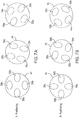
- Figs. 7A and 7B show alternative orientations of rollers 56.
- Fig. 7A shows rollers 56 in three positions with rollers 56 oriented in the same direction throughout their rotation. At the first position, rollers 56a have their outermost edge in vertical alignment with outer troweling surface 44 of the troweling cylinder and rollers 56b are spaced apart from outer troweling surface 44. As rollers 56 rotate, shown in the second position, the outermost edges of rollers 56a rotate away from the outer troweling surface 44. In the third position, rollers 56b have their outermost edge in vertical alignment with the outer troweling surface 44 of troweling cylinder sidewall 42 and rollers 56a are spaced apart from outer troweling surface 44.
- Fig. 7B shows rollers 56 in three positions with opposing rollers 56a and opposing rollers 56b ninety degrees out of phase with respect to each other throughout their rotation.
- rollers 56a and 56b At the first position, rollers 56a and 56b have their outermost edge in vertical alignment with the outer troweling surface 44 of troweling cylinder sidewall 42.
- the outermost edges of rollers 56a and 56b rotate away from the outer troweling surface 44.
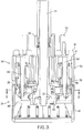
- FIG. 3 shows each roller 56 with a downwardly extending support shaft 64 that is rotatably mounted in a bore formed in a cylindrical bearing unit 68 fixed to and depending from the head plate 38.
- the bearing unit 68 has an annular collar 70 that is received in head plate 38.
- Each collar 70 has a height which will keep the bottom of roller 56 slightly spaced from the top of the head plate 38 so that there is adequate clearance for the rollers 56 to rotate.
- Also included in the bearing unit 68 is a set of conventional ball bearings, which surround the support shaft 64 and allow each roller 56 to freely rotate relative to the head plate 38.
- a transmission arrangement interconnects each roller 56 in a manner that will synchronize the rotation and speed of the rollers 56 and equalize frictional forces should any of the friction driven rollers 56 become stuck or jammed because of concrete or other particles becoming lodged between the bottom of the roller 56 and the top of the head plate 38.
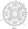
- Fig. 4 shows four tooth-engaging drive sprockets 82, each keyed to the bottom end of each support shaft 64, such that rotation of the drive sprocket 82 will turn the support shaft 64 and the roller 56 relative to its bearing unit 68.
- Drive sprockets 82 are positioned on support shafts 64 such that they all lie in the same horizontal plane.
- Four spaced idler sprockets 84 having depending cylindrical sleeves 85 are rotatably supported on shafts 86 that are fixed to and extend downwardly from the bottom of head plate 38. Each idler sprocket 84 lies in the same horizontal plane as the drive sprockets 82.
- a linkage arrangement 90 interconnects each drive sprocket 82 along an outer peripheral portion and idler sprockets 84 along an inner peripheral portion and over a winding path.
- the linkage arrangement 90 takes the form of a chain, although it should be understood that a belt, gears or another suitable transmission arrangement could likewise be employed.
- Drive sprockets 82, idler sprockets 84, and linkage arrangement 90 define a synchronous friction drive for collectively driving the rollers 56 without sticking.
- FIG. 3 shows troweling cylinder assembly 34, which is mounted underneath circular plate 38 and connected to drive shaft 24 by a collar 72.
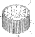
- FIG. 5 shows troweling cylinder assembly 34 removed from extruder head assembly 12.
- Collar 72 is connected to an inner circular flange 80 by several bolts 81, so that rotation of drive shaft 24 causes rotation of troweling cylinder assembly 34 in the same direction.
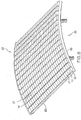
- the outer troweling surface 44 of the troweling cylinder assembly 34 has a segmented smooth outer surface comprised of a plurality of tiles 87 combined to segments of a steel plate 88 and positioned in grooves 89 in plate 88, as shown in Fig. 6 .
- the troweling cylinder assembly 34 is composed of a plurality of individual sections 83, each of which is contoured, when assembled, to form a circular outer periphery.
- Tiles 87 are made from an alumina, such as AL2O3, a tungsten carbide, or a similar ceramic or carbide material. Tiles 87 are less expensive that using a steel outer surface and they can be easily replaced once they begin to show signs of wear. Tiles 87 have may be brittle, so they are held in place with an elastic polymer, which provides elasticity for tiles 87 to prevent cracking. Grooves 89 in steel plate 88 provide a high strength structure that can absorb the shearing force on tiles 87 as trowel 34 is rotated against the concrete, which also prevents tiles 87 from cracking. If, however, tiles 87 crack, an entire outer section 83 can be removed and placed in a kiln to melt the polymer so the broken tiles 87 can be removed and replaced.
- alumina such as AL2O3, a tungsten carbide, or a similar ceramic or carbide material.
- extruder head assembly 12 is first positioned in the bottom of the jacket adjacent to the pallet. Concrete 30 is then moved by a conveyor into the funneling mouth on the top table and dropped onto extruder head assembly 12. Drive shaft 24 is then operated to rotate head plate 38 and troweling cylinder assembly 34 in one direction. As troweling cylinder assembly 34 rotates, the friction driven rollers 56 are rotated in an opposite direction by engagement with the concrete to form the concrete pipe as the extruder head assembly 12 moves up the mold. Concrete that is deposited on top of extruder head assembly 12 is slung by vanes 92 and 93 to the outside walls of the jacket. Thereafter, the concrete is acted upon by rollers 56 in an oscillatory motion to compact the concrete. As the extruder head assembly 12 is further rotated and lifted, the concrete is engaged by the smooth outer surface 44 formed from all of the individually spaced tiles 82 of the troweling cylinder assembly to provide a smooth finish to the inside surface of the finished concrete pipe.
- roller assemblies 36 include a plurality of round rollers eccentric from an axis defined by downwardly extending support shaft 64.
- round rollers spinning about eccentric axes have a similar affect as use of non-round rollers. The rotation causes an oscillating impacting force against the inside surface of the concrete pipe to increase compaction of the concrete similar to a repeated paddling by the rollers against the wet concrete mixture.
Landscapes
- Engineering & Computer Science (AREA)
- Chemical & Material Sciences (AREA)
- Ceramic Engineering (AREA)
- Mechanical Engineering (AREA)
- Manufacturing & Machinery (AREA)
- Structural Engineering (AREA)
- Devices For Post-Treatments, Processing, Supply, Discharge, And Other Processes (AREA)
- Manufacturing Of Tubular Articles Or Embedded Moulded Articles (AREA)
Applications Claiming Priority (3)
| Application Number | Priority Date | Filing Date | Title |
|---|---|---|---|
| US201261646592P | 2012-05-14 | 2012-05-14 | |
| EP13720680.1A EP2849922B1 (en) | 2012-05-14 | 2013-04-23 | Concrete roller head |
| PCT/US2013/037704 WO2013173030A1 (en) | 2012-05-14 | 2013-04-23 | Concrete roller head |
Related Parent Applications (2)
| Application Number | Title | Priority Date | Filing Date |
|---|---|---|---|
| EP13720680.1A Division-Into EP2849922B1 (en) | 2012-05-14 | 2013-04-23 | Concrete roller head |
| EP13720680.1A Division EP2849922B1 (en) | 2012-05-14 | 2013-04-23 | Concrete roller head |
Publications (2)
| Publication Number | Publication Date |
|---|---|
| EP3020526A1 EP3020526A1 (en) | 2016-05-18 |
| EP3020526B1 true EP3020526B1 (en) | 2019-06-26 |
Family
ID=48289662
Family Applications (2)
| Application Number | Title | Priority Date | Filing Date |
|---|---|---|---|
| EP15200837.1A Active EP3020526B1 (en) | 2012-05-14 | 2013-04-23 | Concrete roller head |
| EP13720680.1A Active EP2849922B1 (en) | 2012-05-14 | 2013-04-23 | Concrete roller head |
Family Applications After (1)
| Application Number | Title | Priority Date | Filing Date |
|---|---|---|---|
| EP13720680.1A Active EP2849922B1 (en) | 2012-05-14 | 2013-04-23 | Concrete roller head |
Country Status (6)
| Country | Link |
|---|---|
| US (1) | US8979520B2 (enExample) |
| EP (2) | EP3020526B1 (enExample) |
| AU (1) | AU2013263323B2 (enExample) |
| BR (1) | BR112014028285B1 (enExample) |
| IN (1) | IN2014DN09598A (enExample) |
| WO (1) | WO2013173030A1 (enExample) |
Cited By (1)
| Publication number | Priority date | Publication date | Assignee | Title |
|---|---|---|---|---|
| CN111456464A (zh) * | 2020-04-30 | 2020-07-28 | 梁利生 | 一种建筑施工孔洞处理装置 |
Families Citing this family (2)
| Publication number | Priority date | Publication date | Assignee | Title |
|---|---|---|---|---|
| CN107188611B (zh) * | 2017-07-06 | 2023-01-20 | 吴泉兴 | 一种混凝土智能养护设备以及养护方法 |
| CN115351889B (zh) * | 2022-09-13 | 2024-06-21 | 阳城县华冠陶瓷有限公司 | 一种用于瓷砖打蜡装置的大转盘及瓷砖打蜡装置 |
Family Cites Families (13)
| Publication number | Priority date | Publication date | Assignee | Title |
|---|---|---|---|---|
| US3276091A (en) * | 1964-04-20 | 1966-10-04 | Charles B Pausch | Roller head for cement pipe forming |
| US3733163A (en) * | 1970-09-01 | 1973-05-15 | Concrete Pipe Mach Co | Wear surface for concrete pipe machine long bottoms |
| SU903125A1 (ru) * | 1980-03-14 | 1982-02-07 | Киевский Филиал Конструкторско-Технологического Бюро "Стройиндустрия" | Головка станка дл радиального уплотнени трубчатых изделий из бетонных смесей |
| US4407648A (en) | 1980-09-18 | 1983-10-04 | Hydrotile Machinery Company | Counter rotating packerhead assembly |
| FI73170C (fi) * | 1984-04-24 | 1990-02-16 | Partek Ab | Foerfarande och anordning foer gjutning av betongprodukter. |
| SU1202892A1 (ru) * | 1984-07-24 | 1986-01-07 | Всесоюзный научно-исследовательский институт транспортного строительства | Устройство дл радиального прессовани трубчатых изделий |
| DE3807511A1 (de) | 1988-03-08 | 1989-09-21 | Gregor Kern | Verfahren zur herstellung von betonrohren und rohrpresse zur durchfuehrung des verfahrens |
| SU1671461A1 (ru) * | 1988-06-30 | 1991-08-23 | Предприятие П/Я Р-6719 | Головка к трубоформочному станку радиального прессовани |
| US5080571A (en) * | 1990-02-28 | 1992-01-14 | International Pipe Machinery Corporation | Packerhead assembly |
| RU1794029C (ru) | 1991-06-17 | 1993-02-07 | Нижегородский архитектурно-строительный институт | Головка дл радиального прессовани трубчатых изделий |
| US6017208A (en) * | 1997-05-28 | 2000-01-25 | Concrete Technology Integrators, Inc. | Chain driven roller system for use in concrete pipe manufacturing |
| DE10253209A1 (de) * | 2002-11-15 | 2004-05-27 | ETEC Gesellschaft für technische Keramik mbH | Montagesystem für allseitig kantengeschützte Verschleißschutzkassetten, insbesondere aus Keramik |
| US7125239B2 (en) | 2003-04-07 | 2006-10-24 | International Pipe Machinery Corporation | Concrete pipe manufacturing machinery and methods |
-
2013
- 2013-04-23 US US13/868,271 patent/US8979520B2/en active Active
- 2013-04-23 WO PCT/US2013/037704 patent/WO2013173030A1/en not_active Ceased
- 2013-04-23 EP EP15200837.1A patent/EP3020526B1/en active Active
- 2013-04-23 AU AU2013263323A patent/AU2013263323B2/en active Active
- 2013-04-23 EP EP13720680.1A patent/EP2849922B1/en active Active
- 2013-04-23 BR BR112014028285-4A patent/BR112014028285B1/pt not_active IP Right Cessation
- 2013-04-23 IN IN9598DEN2014 patent/IN2014DN09598A/en unknown
Non-Patent Citations (1)
| Title |
|---|
| None * |
Cited By (1)
| Publication number | Priority date | Publication date | Assignee | Title |
|---|---|---|---|---|
| CN111456464A (zh) * | 2020-04-30 | 2020-07-28 | 梁利生 | 一种建筑施工孔洞处理装置 |
Also Published As
| Publication number | Publication date |
|---|---|
| US8979520B2 (en) | 2015-03-17 |
| AU2013263323B2 (en) | 2017-06-15 |
| EP2849922A1 (en) | 2015-03-25 |
| EP2849922B1 (en) | 2018-11-14 |
| US20130302462A1 (en) | 2013-11-14 |
| BR112014028285A2 (pt) | 2017-07-18 |
| EP3020526A1 (en) | 2016-05-18 |
| BR112014028285B1 (pt) | 2021-09-21 |
| AU2013263323A1 (en) | 2014-11-27 |
| IN2014DN09598A (enExample) | 2015-07-31 |
| WO2013173030A1 (en) | 2013-11-21 |
Similar Documents
| Publication | Publication Date | Title |
|---|---|---|
| EP3020526B1 (en) | Concrete roller head | |
| CN109624042B (zh) | 一种预应力管桩生产系统 | |
| CN106827220A (zh) | 一种建筑材料成型生产线 | |
| CN106827229A (zh) | 一种建筑材料成型装置 | |
| CN116079882A (zh) | 一种混凝土预制件翻转脱模装置 | |
| CN120922567A (zh) | 一种含油轴承自动输送装置 | |
| US6017208A (en) | Chain driven roller system for use in concrete pipe manufacturing | |
| CN107348037B (zh) | 一种茶叶加工装置 | |
| CN112722490B (zh) | 一种包装机送料装置 | |
| CN115110381B (zh) | 一种公路基层稳定土的铺设装置 | |
| CN211190927U (zh) | 一种隔离圈与料柄自动分离的震动装置 | |
| KR100473689B1 (ko) | 원심 성형장치 | |
| US20160236374A1 (en) | Packerhead machine | |
| US20030190384A1 (en) | Concrete rollerhead assembly | |
| CN108858685A (zh) | 一种免托板出砖装置及静压砌块成型机 | |
| KR20140005725A (ko) | 자동차 시동장치의 피니언기어유닛에 대한 자동 연마장치 | |
| CN201399914Y (zh) | 杂物无阻碍直通式环模成型机 | |
| JP2018030666A (ja) | 絡み部品分離装置 | |
| CN217494667U (zh) | 一种带角度的离心布料设备 | |
| CN110694893B (zh) | 一种隔离圈与料柄自动分离的震动装置 | |
| CN216931732U (zh) | 一种棉花糖机的送棒结构 | |
| CN118373178A (zh) | 一种钢球自动化填装系统及其填装方法 | |
| KR100473690B1 (ko) | 경계석 제조형틀 | |
| JP3059914U (ja) | 生コンクリート投入装置 | |
| CN113263618B (zh) | 机制砂混凝土生产装置 |
Legal Events
| Date | Code | Title | Description |
|---|---|---|---|
| PUAI | Public reference made under article 153(3) epc to a published international application that has entered the european phase |
Free format text: ORIGINAL CODE: 0009012 |
|
| AC | Divisional application: reference to earlier application |
Ref document number: 2849922 Country of ref document: EP Kind code of ref document: P |
|
| AK | Designated contracting states |
Kind code of ref document: A1 Designated state(s): AL AT BE BG CH CY CZ DE DK EE ES FI FR GB GR HR HU IE IS IT LI LT LU LV MC MK MT NL NO PL PT RO RS SE SI SK SM TR |
|
| 17P | Request for examination filed |
Effective date: 20160919 |
|
| RBV | Designated contracting states (corrected) |
Designated state(s): AL AT BE BG CH CY CZ DE DK EE ES FI FR GB GR HR HU IE IS IT LI LT LU LV MC MK MT NL NO PL PT RO RS SE SI SK SM TR |
|
| RAP1 | Party data changed (applicant data changed or rights of an application transferred) |
Owner name: HAWKEYEPEDERSHAAB CONCRETE TECHNOLOGIES, INC. |
|
| STAA | Information on the status of an ep patent application or granted ep patent |
Free format text: STATUS: EXAMINATION IS IN PROGRESS |
|
| 17Q | First examination report despatched |
Effective date: 20180912 |
|
| GRAP | Despatch of communication of intention to grant a patent |
Free format text: ORIGINAL CODE: EPIDOSNIGR1 |
|
| STAA | Information on the status of an ep patent application or granted ep patent |
Free format text: STATUS: GRANT OF PATENT IS INTENDED |
|
| INTG | Intention to grant announced |
Effective date: 20190404 |
|
| RIN1 | Information on inventor provided before grant (corrected) |
Inventor name: SUBACCHI, CLAUDIO |
|
| GRAS | Grant fee paid |
Free format text: ORIGINAL CODE: EPIDOSNIGR3 |
|
| RAP1 | Party data changed (applicant data changed or rights of an application transferred) |
Owner name: HAWKEYEPEDERSHAAB CONCRETE TECHNOLOGIES, INC. |
|
| GRAA | (expected) grant |
Free format text: ORIGINAL CODE: 0009210 |
|
| STAA | Information on the status of an ep patent application or granted ep patent |
Free format text: STATUS: THE PATENT HAS BEEN GRANTED |
|
| AC | Divisional application: reference to earlier application |
Ref document number: 2849922 Country of ref document: EP Kind code of ref document: P |
|
| AK | Designated contracting states |
Kind code of ref document: B1 Designated state(s): AL AT BE BG CH CY CZ DE DK EE ES FI FR GB GR HR HU IE IS IT LI LT LU LV MC MK MT NL NO PL PT RO RS SE SI SK SM TR |
|
| REG | Reference to a national code |
Ref country code: GB Ref legal event code: FG4D |
|
| REG | Reference to a national code |
Ref country code: CH Ref legal event code: EP |
|
| REG | Reference to a national code |
Ref country code: AT Ref legal event code: REF Ref document number: 1147779 Country of ref document: AT Kind code of ref document: T Effective date: 20190715 |
|
| REG | Reference to a national code |
Ref country code: DE Ref legal event code: R096 Ref document number: 602013057276 Country of ref document: DE |
|
| REG | Reference to a national code |
Ref country code: IE Ref legal event code: FG4D |
|
| REG | Reference to a national code |
Ref country code: NL Ref legal event code: MP Effective date: 20190626 |
|
| PG25 | Lapsed in a contracting state [announced via postgrant information from national office to epo] |
Ref country code: AL Free format text: LAPSE BECAUSE OF FAILURE TO SUBMIT A TRANSLATION OF THE DESCRIPTION OR TO PAY THE FEE WITHIN THE PRESCRIBED TIME-LIMIT Effective date: 20190626 Ref country code: SE Free format text: LAPSE BECAUSE OF FAILURE TO SUBMIT A TRANSLATION OF THE DESCRIPTION OR TO PAY THE FEE WITHIN THE PRESCRIBED TIME-LIMIT Effective date: 20190626 Ref country code: HR Free format text: LAPSE BECAUSE OF FAILURE TO SUBMIT A TRANSLATION OF THE DESCRIPTION OR TO PAY THE FEE WITHIN THE PRESCRIBED TIME-LIMIT Effective date: 20190626 Ref country code: NO Free format text: LAPSE BECAUSE OF FAILURE TO SUBMIT A TRANSLATION OF THE DESCRIPTION OR TO PAY THE FEE WITHIN THE PRESCRIBED TIME-LIMIT Effective date: 20190926 Ref country code: FI Free format text: LAPSE BECAUSE OF FAILURE TO SUBMIT A TRANSLATION OF THE DESCRIPTION OR TO PAY THE FEE WITHIN THE PRESCRIBED TIME-LIMIT Effective date: 20190626 Ref country code: LT Free format text: LAPSE BECAUSE OF FAILURE TO SUBMIT A TRANSLATION OF THE DESCRIPTION OR TO PAY THE FEE WITHIN THE PRESCRIBED TIME-LIMIT Effective date: 20190626 |
|
| REG | Reference to a national code |
Ref country code: LT Ref legal event code: MG4D |
|
| PG25 | Lapsed in a contracting state [announced via postgrant information from national office to epo] |
Ref country code: RS Free format text: LAPSE BECAUSE OF FAILURE TO SUBMIT A TRANSLATION OF THE DESCRIPTION OR TO PAY THE FEE WITHIN THE PRESCRIBED TIME-LIMIT Effective date: 20190626 Ref country code: LV Free format text: LAPSE BECAUSE OF FAILURE TO SUBMIT A TRANSLATION OF THE DESCRIPTION OR TO PAY THE FEE WITHIN THE PRESCRIBED TIME-LIMIT Effective date: 20190626 Ref country code: GR Free format text: LAPSE BECAUSE OF FAILURE TO SUBMIT A TRANSLATION OF THE DESCRIPTION OR TO PAY THE FEE WITHIN THE PRESCRIBED TIME-LIMIT Effective date: 20190927 Ref country code: BG Free format text: LAPSE BECAUSE OF FAILURE TO SUBMIT A TRANSLATION OF THE DESCRIPTION OR TO PAY THE FEE WITHIN THE PRESCRIBED TIME-LIMIT Effective date: 20190926 |
|
| PG25 | Lapsed in a contracting state [announced via postgrant information from national office to epo] |
Ref country code: PT Free format text: LAPSE BECAUSE OF FAILURE TO SUBMIT A TRANSLATION OF THE DESCRIPTION OR TO PAY THE FEE WITHIN THE PRESCRIBED TIME-LIMIT Effective date: 20191028 Ref country code: SK Free format text: LAPSE BECAUSE OF FAILURE TO SUBMIT A TRANSLATION OF THE DESCRIPTION OR TO PAY THE FEE WITHIN THE PRESCRIBED TIME-LIMIT Effective date: 20190626 Ref country code: EE Free format text: LAPSE BECAUSE OF FAILURE TO SUBMIT A TRANSLATION OF THE DESCRIPTION OR TO PAY THE FEE WITHIN THE PRESCRIBED TIME-LIMIT Effective date: 20190626 Ref country code: RO Free format text: LAPSE BECAUSE OF FAILURE TO SUBMIT A TRANSLATION OF THE DESCRIPTION OR TO PAY THE FEE WITHIN THE PRESCRIBED TIME-LIMIT Effective date: 20190626 Ref country code: CZ Free format text: LAPSE BECAUSE OF FAILURE TO SUBMIT A TRANSLATION OF THE DESCRIPTION OR TO PAY THE FEE WITHIN THE PRESCRIBED TIME-LIMIT Effective date: 20190626 Ref country code: NL Free format text: LAPSE BECAUSE OF FAILURE TO SUBMIT A TRANSLATION OF THE DESCRIPTION OR TO PAY THE FEE WITHIN THE PRESCRIBED TIME-LIMIT Effective date: 20190626 |
|
| PG25 | Lapsed in a contracting state [announced via postgrant information from national office to epo] |
Ref country code: ES Free format text: LAPSE BECAUSE OF FAILURE TO SUBMIT A TRANSLATION OF THE DESCRIPTION OR TO PAY THE FEE WITHIN THE PRESCRIBED TIME-LIMIT Effective date: 20190626 Ref country code: IS Free format text: LAPSE BECAUSE OF FAILURE TO SUBMIT A TRANSLATION OF THE DESCRIPTION OR TO PAY THE FEE WITHIN THE PRESCRIBED TIME-LIMIT Effective date: 20191026 Ref country code: SM Free format text: LAPSE BECAUSE OF FAILURE TO SUBMIT A TRANSLATION OF THE DESCRIPTION OR TO PAY THE FEE WITHIN THE PRESCRIBED TIME-LIMIT Effective date: 20190626 |
|
| PG25 | Lapsed in a contracting state [announced via postgrant information from national office to epo] |
Ref country code: TR Free format text: LAPSE BECAUSE OF FAILURE TO SUBMIT A TRANSLATION OF THE DESCRIPTION OR TO PAY THE FEE WITHIN THE PRESCRIBED TIME-LIMIT Effective date: 20190626 |
|
| PG25 | Lapsed in a contracting state [announced via postgrant information from national office to epo] |
Ref country code: PL Free format text: LAPSE BECAUSE OF FAILURE TO SUBMIT A TRANSLATION OF THE DESCRIPTION OR TO PAY THE FEE WITHIN THE PRESCRIBED TIME-LIMIT Effective date: 20190626 Ref country code: DK Free format text: LAPSE BECAUSE OF FAILURE TO SUBMIT A TRANSLATION OF THE DESCRIPTION OR TO PAY THE FEE WITHIN THE PRESCRIBED TIME-LIMIT Effective date: 20190626 |
|
| PG25 | Lapsed in a contracting state [announced via postgrant information from national office to epo] |
Ref country code: IS Free format text: LAPSE BECAUSE OF FAILURE TO SUBMIT A TRANSLATION OF THE DESCRIPTION OR TO PAY THE FEE WITHIN THE PRESCRIBED TIME-LIMIT Effective date: 20200224 |
|
| REG | Reference to a national code |
Ref country code: DE Ref legal event code: R097 Ref document number: 602013057276 Country of ref document: DE |
|
| PLBE | No opposition filed within time limit |
Free format text: ORIGINAL CODE: 0009261 |
|
| STAA | Information on the status of an ep patent application or granted ep patent |
Free format text: STATUS: NO OPPOSITION FILED WITHIN TIME LIMIT |
|
| PG2D | Information on lapse in contracting state deleted |
Ref country code: IS |
|
| 26N | No opposition filed |
Effective date: 20200603 |
|
| PG25 | Lapsed in a contracting state [announced via postgrant information from national office to epo] |
Ref country code: SI Free format text: LAPSE BECAUSE OF FAILURE TO SUBMIT A TRANSLATION OF THE DESCRIPTION OR TO PAY THE FEE WITHIN THE PRESCRIBED TIME-LIMIT Effective date: 20190626 |
|
| PG25 | Lapsed in a contracting state [announced via postgrant information from national office to epo] |
Ref country code: MC Free format text: LAPSE BECAUSE OF FAILURE TO SUBMIT A TRANSLATION OF THE DESCRIPTION OR TO PAY THE FEE WITHIN THE PRESCRIBED TIME-LIMIT Effective date: 20190626 |
|
| REG | Reference to a national code |
Ref country code: CH Ref legal event code: PL |
|
| REG | Reference to a national code |
Ref country code: AT Ref legal event code: UEP Ref document number: 1147779 Country of ref document: AT Kind code of ref document: T Effective date: 20190626 |
|
| PG25 | Lapsed in a contracting state [announced via postgrant information from national office to epo] |
Ref country code: CH Free format text: LAPSE BECAUSE OF NON-PAYMENT OF DUE FEES Effective date: 20200430 Ref country code: FR Free format text: LAPSE BECAUSE OF NON-PAYMENT OF DUE FEES Effective date: 20200430 Ref country code: LI Free format text: LAPSE BECAUSE OF NON-PAYMENT OF DUE FEES Effective date: 20200430 Ref country code: LU Free format text: LAPSE BECAUSE OF NON-PAYMENT OF DUE FEES Effective date: 20200423 |
|
| REG | Reference to a national code |
Ref country code: BE Ref legal event code: MM Effective date: 20200430 |
|
| PG25 | Lapsed in a contracting state [announced via postgrant information from national office to epo] |
Ref country code: BE Free format text: LAPSE BECAUSE OF NON-PAYMENT OF DUE FEES Effective date: 20200430 |
|
| GBPC | Gb: european patent ceased through non-payment of renewal fee |
Effective date: 20200423 |
|
| PG25 | Lapsed in a contracting state [announced via postgrant information from national office to epo] |
Ref country code: GB Free format text: LAPSE BECAUSE OF NON-PAYMENT OF DUE FEES Effective date: 20200423 Ref country code: IE Free format text: LAPSE BECAUSE OF NON-PAYMENT OF DUE FEES Effective date: 20200423 |
|
| PG25 | Lapsed in a contracting state [announced via postgrant information from national office to epo] |
Ref country code: MT Free format text: LAPSE BECAUSE OF FAILURE TO SUBMIT A TRANSLATION OF THE DESCRIPTION OR TO PAY THE FEE WITHIN THE PRESCRIBED TIME-LIMIT Effective date: 20190626 Ref country code: CY Free format text: LAPSE BECAUSE OF FAILURE TO SUBMIT A TRANSLATION OF THE DESCRIPTION OR TO PAY THE FEE WITHIN THE PRESCRIBED TIME-LIMIT Effective date: 20190626 |
|
| PG25 | Lapsed in a contracting state [announced via postgrant information from national office to epo] |
Ref country code: MK Free format text: LAPSE BECAUSE OF FAILURE TO SUBMIT A TRANSLATION OF THE DESCRIPTION OR TO PAY THE FEE WITHIN THE PRESCRIBED TIME-LIMIT Effective date: 20190626 |
|
| PGFP | Annual fee paid to national office [announced via postgrant information from national office to epo] |
Ref country code: DE Payment date: 20230427 Year of fee payment: 11 |
|
| PGFP | Annual fee paid to national office [announced via postgrant information from national office to epo] |
Ref country code: AT Payment date: 20240417 Year of fee payment: 12 |
|
| PGFP | Annual fee paid to national office [announced via postgrant information from national office to epo] |
Ref country code: IT Payment date: 20240430 Year of fee payment: 12 |
|
| REG | Reference to a national code |
Ref country code: DE Ref legal event code: R119 Ref document number: 602013057276 Country of ref document: DE |
|
| REG | Reference to a national code |
Ref country code: AT Ref legal event code: MM01 Ref document number: 1147779 Country of ref document: AT Kind code of ref document: T Effective date: 20250423 |