EP3020061B1 - Rotating anode mount adaptive to thermal expansion - Google Patents
Rotating anode mount adaptive to thermal expansion Download PDFInfo
- Publication number
- EP3020061B1 EP3020061B1 EP14738419.2A EP14738419A EP3020061B1 EP 3020061 B1 EP3020061 B1 EP 3020061B1 EP 14738419 A EP14738419 A EP 14738419A EP 3020061 B1 EP3020061 B1 EP 3020061B1
- Authority
- EP
- European Patent Office
- Prior art keywords
- support
- axial
- anode
- rotating shaft
- anode disk
- Prior art date
- Legal status (The legal status is an assumption and is not a legal conclusion. Google has not performed a legal analysis and makes no representation as to the accuracy of the status listed.)
- Active
Links
Images


Classifications
-
- H—ELECTRICITY
- H01—ELECTRIC ELEMENTS
- H01J—ELECTRIC DISCHARGE TUBES OR DISCHARGE LAMPS
- H01J35/00—X-ray tubes
- H01J35/02—Details
- H01J35/04—Electrodes ; Mutual position thereof; Constructional adaptations therefor
- H01J35/08—Anodes; Anti cathodes
- H01J35/10—Rotary anodes; Arrangements for rotating anodes; Cooling rotary anodes
- H01J35/101—Arrangements for rotating anodes, e.g. supporting means, means for greasing, means for sealing the axle or means for shielding or protecting the driving
- H01J35/1017—Bearings for rotating anodes
-
- H—ELECTRICITY
- H01—ELECTRIC ELEMENTS
- H01J—ELECTRIC DISCHARGE TUBES OR DISCHARGE LAMPS
- H01J9/00—Apparatus or processes specially adapted for the manufacture, installation, removal, maintenance of electric discharge tubes, discharge lamps, or parts thereof; Recovery of material from discharge tubes or lamps
- H01J9/02—Manufacture of electrodes or electrode systems
- H01J9/14—Manufacture of electrodes or electrode systems of non-emitting electrodes
- H01J9/148—Manufacture of electrodes or electrode systems of non-emitting electrodes of electron emission flat panels, e.g. gate electrodes, focusing electrodes or anode electrodes
-
- H—ELECTRICITY
- H01—ELECTRIC ELEMENTS
- H01J—ELECTRIC DISCHARGE TUBES OR DISCHARGE LAMPS
- H01J2235/00—X-ray tubes
- H01J2235/10—Drive means for anode (target) substrate
- H01J2235/1006—Supports or shafts for target or substrate
-
- H—ELECTRICITY
- H01—ELECTRIC ELEMENTS
- H01J—ELECTRIC DISCHARGE TUBES OR DISCHARGE LAMPS
- H01J2235/00—X-ray tubes
- H01J2235/10—Drive means for anode (target) substrate
- H01J2235/1006—Supports or shafts for target or substrate
- H01J2235/1013—Fixing to the target or substrate
-
- H—ELECTRICITY
- H01—ELECTRIC ELEMENTS
- H01J—ELECTRIC DISCHARGE TUBES OR DISCHARGE LAMPS
- H01J2235/00—X-ray tubes
- H01J2235/10—Drive means for anode (target) substrate
- H01J2235/1046—Bearings and bearing contact surfaces
Definitions
- the present invention relates to mounting of an anode disk, and relates in particular to a rotating anode assembly, to an X-ray tube, to an X-ray imaging system, to a method for mounting a rotating anode disk, and to a use of a support in an X-ray tube for mounting an anode disk to a rotating shaft.
- thermal expansion results in parts of the anode disk may experience deformation in radial direction due to the thermal gradients and different expansion coefficient of the used materials.
- an off-centre positioning of the anode disk may occur during operation.
- this results in an imbalance, and together with the rotation velocity, this may cause unwanted vibration and noise.
- thermal expansion related issues of the mounting of the anode disk also increase.
- JP2011/238549A discloses a rotating anode assembly including an anode disk support.
- JP55-3181A discloses a rotary anode structure for an x-ray tube.
- US2004/234033A1 discloses a rotary anode type X-ray tube using dynamic pressure type sliding bearings.
- a rotating anode assembly comprising an anode disk having a bore, a rotating shaft, and an anode disk support.
- the anode disk is concentrically mounted to a rotating axis of the rotating shaft via the anode disk support.
- the anode disk support comprises a first support with a first circular axial support surface that is provided at the rotating shaft in a concentric manner with the rotating axis.
- the anode disk support comprises a second support with a second axial support surface that is at least temporarily attached to the rotating shaft for urging the anode disk against the first support surface in an axial clamping direction.
- the first support is provided as a radially flexible support.
- the radially flexible support bends radially such that the first axial support surface at least partly follows the thermal expansion in a radial direction.
- the first support has a larger resistance to forces in the axial direction than in the radial direction.
- the first support is provided protruding in an axial direction from a shoulder on the rotating shaft and at least a circumferential radial gap to a shaft-end extending through the bore of the anode disk is provided.
- the first support is provided with a radial width and an axial height and the axial height is at least the double amount of the radial width.
- the anode disk is securely supported even though a certain deformation caused by thermal expansion may occur.
- the contact portions where the clamping of the anode disk occurs remain stable. In other words, friction between two contacting surfaces of the anode attached to the rotating shaft is avoided, or at least reduced to a minimum.
- the first support has a larger resistance to forces in the axial direction than in the radial direction.
- this can be achieved by different geometric relations and proportions as described below, or with different metarial characteristics.
- the first axial support surface compensates for thermal expansion of the anode disk such that, during the thermal expansion, a first contact area of the first support surface and a second contact area of the anode disk commonly move in relation to the rotating axis such that the contact is maintained.
- the shoulder is formed by a stepweise recess of the outer diameter of the rotating shaft.
- the recess is forming a sort of end face of the part of the diamater of the shaft that has a larger diameter.
- the shoulder is provided by a cantilevering dircumferational protrusion, extending beyond the outer diameter of the adjacant shaft surface.
- the first support comprises an axial circular collar protruding from a shoulder on the rotating shaft in an axial direction with a clearance groove between the collar and the rotating shaft.
- the first support comprises a plurality of radially flexible support elements that provide a plurality of first axial support surface portions.
- a heat transfer element is provided between the radially flexible support and the rotating shaft for heat conduction via the rotating shaft.
- the heat transfer element provides a further thermal pathway, while not influencing any supporting forces and other aspects of the support.
- the bending of the radially flexible support is restricted to an elastic deformation.
- the second support is provided with a second circular axial support surface.
- the second support is also provided as a radially flexible support. Upon heating up of the anode disk during X-ray generation, and a thermal expansion of the anode disk, the radially flexible support of the second support bends radially such that the second axial support surface at least partly follows the thermal expansion in a radial direction.
- an X-ray tube comprising an X-ray vacuum housing, an anode, a cathode, and a bearing arrangement for supporting the anode.
- the anode and the cathode are arranged inside the X-ray vacuum housing.
- the anode is provided as a rotating anode assembly according to one of the above-mentioned examples.
- the bearing arrangement is arranged inside the X-ray vacuum housing supporting the rotating shaft.
- the bearing arrangement comprises at least one spiral groove bearing.
- an improved fixation of the anode disk is provided, meaning an improved positioning of the center of the anode disk aligned with the rotation axis.
- This is in particular suitable in combination with spiral groove bearings that go along with an increased demand for accuracy in terms of imbalance causing vibrations.
- the rotating shaft is provided hollow with a bore and a fixed shaft is provided inside the bore, supporting the rotating shaft.
- the rotating shaft is supported by the fixed shaft with a spiral groove bearing arrangement.
- an X-ray imaging system comprising an X-ray acquisition device with an X-ray source and an X-ray detector, as well as an object support.
- the object support is arranged between the X-ray source and the X-ray detector for radiating the object with X-rays provided by the X-ray source.
- the X-ray source comprises an X-ray tube according to the above-mentioned examples.
- a support in an X-ray tube for mounting an anode disk to a rotating shaft comprises a first support with a first axial support surface that is provided at a rotating shaft in a concentric manner around a rotating axis.
- a second support with a second axial support surface is provided.
- the second support is at least temporarily attached to the rotating shaft for urging an anode disk against the first support in an axial clamping direction.
- the first support is provided as a radially flexible support. Upon heating up of the anode disk during X-ray generation, the radially flexible support bends radially such that the first axial support surface at least partly follows a thermal expansion of the anode disk in a radial direction.
- the first support has a larger resistance to forces in the axial direction than in the radial direction.
- the first support is provided protruding in an axial direction from a shoulder on the rotating shaft and at least a circumferential radial gap to a shaft-end extending through the bore (34) of the anode disk is provided.
- an axial height of the first supoort is at least the double amount of the radial width of the first support.
- a rotating disk is mounted to a rotating shaft in a way that at least on one side of the anode disk, when the disk is clamped in the mounted state, the contacting surfaces remain stable to each other such that no friction occurs and no imbalance is caused.
- the adaption for considering the thermal expansion, i.e. the so-to-speak movement (even though very small) of the support surface portions on the rotating shaft are provided on flexible support elements.
- amending of the support itself is provided for adapting the support to the thermal expansion that occurs during X-ray generation to different degrees, depending on the respective situation.
- a fixed and centric mount of the anode disk is provided, while still allowing the concentric thermal expansion of the anode disk.
- Fig. 1A shows a rotating anode assembly 10, comprising an anode disk 12, a rotating shaft 14, and an anode disk support 16. Further, a rotational axis 18 of the rotating shaft 14 is indicated.
- the anode disk 12 is concentrically mounted to the rotational axis 18 of the rotating shaft 14 via the anode disk support 16.
- the anode disk support 16 comprises a support 20 with a first circular axial support surface 22 that is provided at the rotating shaft 14 in a concentric manner with the rotating axis 18.
- the first support 20 and the first circular axial support surface 22 are further described below.
- the anode disk support 16 also comprises a second support 24 with a second axial support surface 26 that is at least temporarily attached to the rotating shaft 14 for urging the anode disk 12 against the first support surface 22 in an axial clamping direction.
- the first support 20 is provided as a radially flexible support 28, as also shown in Fig. 1B .
- Fig. 1B shows a state where the anode disk 12 is heated up, for example caused by X-ray generation, and a thermal expansion of the anode disk has taken place, as indicated with thermal expansion arrows 30.
- the radially flexible support 28 bends, as indicated with bending arrows 32. The bending takes place radially such that the first axial support surface 22 at least partly follows the thermal expansion in a radial direction, i.e. perpendicular to the rotational axis 18.
- the “anode disk” relates to an anode that has a circular form with a flat shape in the radial direction.
- the anode disk is mounted to the rotating shaft such that the radial direction of the disk is perpendicular to the rotating axis of the shaft.
- the "first circular axial support surface” relates to an abutment surface for the mounting of the anode disk, wherein the abutment takes place in an axial direction, i.e. in a direction of the rotating axis.
- the “second axial support surface” relates to an abutment surface for the mounting of the anode disk, wherein the abutment takes place in an axial direction, i.e. in a direction of the rotating axis.
- the first axial support surface and the second axial support surface are arranged on opposite sides of the anode disk, clamping the rotating disk between. In other words, the first and second axial support surfaces are abutting the rotating disk from two different sides.
- the first circular support surface is also referred to as first interface, and the second circular support surface as second interface.
- the anode disk is provided with a central bore 34.
- the second support is a nut threaded onto an end 36 of the shaft extending through the central bore 34.
- the second support 24 is a bushing.
- the second support is provided by a clamping element that is welded or brazed to the end of the rotating shaft 14.
- the first support surface is integrally formed on the rotating shaft, i.e. as a single workpiece or component.
- Fig. 1B the bending movement illustrated in Fig. 1B is shown in a rather extreme manner for illustrational purposes only. In reality, according to the present invention, the deformation is in a range of, for example, up to 0.5 mm, e.g. up to 0.3 mm or 0.2 mm.
- the bending of the radially flexible support is restricted to an elastic deformation.
- the first support surface 22 is shown in Fig. 1A and Fig. 1B provided on the rotating shaft 14.
- the first axial support surface 22 compensates for thermal expansion of the anode disk 12 such that, during the thermal expansion, a first contact area 38 of the first support surface and a second contact area 40 of the anode disk 12 commonly move in relation to the rotating shaft 14, and also in relation to the rotating axis 18, such that the contact is maintained. In other words, the contact is maintained and a frictional relative movement between the first and the second contact area is prevented, or at least reduced to a minimum.
- the first support 20 is provided with a radial width 42 and an axial height 44, wherein the radial width 42 is smaller than the axial height 44.
- the axial height 44 is at least the double amount of the radial width 42.
- the first support is connected to the rotating shaft by a support base, wherein the support base is provided with a base height in the axial direction.
- the first support 20 is provided protruding in an axial direction from a shoulder 46 on the rotating shaft, wherein, as an option, the shoulder is formed by a stepweise recess of the outer diameter of the rotating shaft.
- At least a circumferential gap 48 to a shaft-end 50 extending through the bore of the anode disk 12 is provided.
- the first support 20 is provided with a distance 52 to the shaft-end 50 extending through the bore of the anode disk 12, wherein the distance 52 is larger than the axial height 44.
- the distance is at least the double amount of the axial height 44.
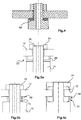
- Fig. 2A shows a further example of the rotating anode assembly 10, where the first support 20 comprises a plurality of radially flexible support elements 54, which are shown in a horizontal cross-section in Fig. 2B .
- the radially flexible support elements provide a plurality of first axial support surface portions 56.
- the radially flexible support elements 54 are provided with a gap 58 to each other.
- the gap is reduced to a minimum such that the adjacent support elements are abutting each other on the side faces in the non-bended state.
- the radially flexible support elements 54 are provided in a castellated manner, which is also referred to as battlement design.
- the radially flexible support elements are provided as thermally dependent radially flexible support elements.
- the support elements are provided with a flexibility that is sufficient enough to allow a bending caused by the thermal expansion of the anode via friction force between the first circular axial support surface and the counterpart on the anode disk surface.
- the friction force is caused by a nut's clamping force.
- the support elements are rigid enough to allow a proper mounting.
- the flexibility is at least twice as large as the friction force, e.g. five times the friction force.
- the radially flexible support elements which are also referred to as pinnacles, are dimensioned such that the friction force at the contact area is sufficient enough to cause an elastic bending of the pinnacles.
- This force is provided by tightening the nut, for example.
- Fig. 3A shows a further example of the first support 20 provided comprising an axial circular collar 60 protruding from a shoulder portion 62 on the rotating shaft 14 in an axial direction with a clearance groove 64 between the collar 60 and the rotating shaft 14.
- the shoulder 62 is provided by a recess of the diameter of the shaft in the radial direction.
- the recess is provided as a step in the diameter of the rotational axis.
- the collar 60 is shown in Fig. 3B in a horizontal cross-section or top view, wherein the collar 60 provides a circular support surface 66. It is noted that the collar 60 is shown in a similar dimension as the flexible support elements 54 for the sake of simplicity. In an example, the collar is provided with a thinner dimension for allowing a similar bending movement as the plurality of the flexible support elements 54.
- a different number of segments for example three segments of the collar of Fig. 3B , are provided.
- a heat transfer element 68 is provided between the radially flexible support and the rotating shaft for heat conduction via the rotating shaft.
- the heat transfer element comprises a heat conduction liquid, for example in a flexible envelope in case of flexible support elements. In case of a continuous collar, the liquid may be provided without an envelope.
- Fig. 5A shows a construction that is not according to the present invention, where the first support 20 is provided as a separate component, for example as a disk 20' having an L-shaped cross-section 69 on either side of the middle portion, having a bore through which the extending part of the rotating shaft extends.
- the separate component is fixedly attached to the rotating shaft, for example by an accurately fitting bore enclosing the rotating shaft.
- the first support is provided as a bushing with a U-shaped cross-section providing a collar that provides the first circular axial support surface.
- care must be taken that a base-point of the axial support surface is fixedly provided in radial direction to the rotational axis.
- Fig. 5B shows a further example, where the radially flexible support 28 is provided with a small gap 70 to the adjacent part of the rotating shaft 14.
- Fig. 5C shows a further example, where, in addition to the radially flexible support 28 of the first support 20, also the second support 24 is provided with a second circular axial support surface 72, provided as a radially flexible support.
- the radially flexible support of the first support 20 as well as the radially flexible support of the second support 24 bends radially such (not further shown) that the first axial support surface and the second axial support surface at least partly follow the thermal expansion in a radial direction.
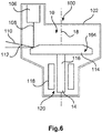
- Fig. 6 shows an X-ray tube 100 comprising an X-ray vacuum housing 102, an anode 104, and a cathode 106.
- An electron beam 108 is schematically shown, generating X-ray radiation 110 emanating through an X-ray transparent window 112 in the X-ray vacuum housing 102.
- the anode 104 and the cathode 106 are arranged inside the X-ray vacuum housing 102.
- the anode 104 is shown with an anode disk 114 mounted to an anode shaft 116.
- a driving mechanism 118 is shown schematically for driving the rotating anode 114 rotating around the rotation axis 18. Further components are provided, but not shown. Still further, not shown in detail, a bearing arrangement for supporting the anode is provided, the bearing arrangement indicated with reference numeral 120.
- the anode 104 is provided as a rotating anode assembly 10 according to one of the above-mentioned examples.
- the bearing arrangement 120 is arranged inside the X-ray vacuum housing 102 supporting the rotating shaft 14, 116.
- the bearing arrangement comprises at least one spiral groove bearing, not further shown.
- the rotating shaft 14 is provided hollow with a bore 74, and a fixed shaft 76 is provided inside the bore 74 supporting with a spiral groove bearing arrangement 78.
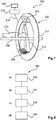
- Fig. 7 shows an example of an X-ray imaging system 200, comprising an X-ray acquisition device 202 with an X-ray source 204 and an X-ray detector 206. Further, an object support 208 is provided. The object support 208 is arranged between the X-ray source 204 and the X-ray detector 206 for radiating the object, for example a patient 210, with X-rays, indicated with fan-shaped structure 212, provided by the X-ray source 204.
- the X-ray source 204 comprises an X-ray tube 100 according to the above-mentioned examples.
- the X-ray imaging system 200 is shown as a CT arrangement with a gantry 214 schematically indicated. Further, a processing unit 216 is data-connected 218, also in combination with a display unit 220.
- CT computed tomography
- other X-ray imaging systems for example a C-arm system or X-ray imaging systems with fixed arrangement of the X-ray source in relation to the object support.
- Fig. 8 shows a method 300 for mounting a rotating anode disk as in the above examples, comprising the following steps:
- the first step 302 is also referred to as step a), the second step 304 as step b), the third step 306 as step c), and the fourth step 308 as step d).
Landscapes
- Engineering & Computer Science (AREA)
- Manufacturing & Machinery (AREA)
- X-Ray Techniques (AREA)
- Apparatus For Radiation Diagnosis (AREA)
Priority Applications (1)
| Application Number | Priority Date | Filing Date | Title |
|---|---|---|---|
| EP14738419.2A EP3020061B1 (en) | 2013-07-11 | 2014-06-20 | Rotating anode mount adaptive to thermal expansion |
Applications Claiming Priority (3)
| Application Number | Priority Date | Filing Date | Title |
|---|---|---|---|
| EP13176026 | 2013-07-11 | ||
| EP14738419.2A EP3020061B1 (en) | 2013-07-11 | 2014-06-20 | Rotating anode mount adaptive to thermal expansion |
| PCT/EP2014/063013 WO2015003886A1 (en) | 2013-07-11 | 2014-06-20 | Rotating anode mount adaptive to thermal expansion |
Publications (2)
| Publication Number | Publication Date |
|---|---|
| EP3020061A1 EP3020061A1 (en) | 2016-05-18 |
| EP3020061B1 true EP3020061B1 (en) | 2020-03-11 |
Family
ID=48748059
Family Applications (1)
| Application Number | Title | Priority Date | Filing Date |
|---|---|---|---|
| EP14738419.2A Active EP3020061B1 (en) | 2013-07-11 | 2014-06-20 | Rotating anode mount adaptive to thermal expansion |
Country Status (5)
| Country | Link |
|---|---|
| US (2) | US9934931B2 (enExample) |
| EP (1) | EP3020061B1 (enExample) |
| JP (1) | JP6318245B2 (enExample) |
| CN (1) | CN105378890B (enExample) |
| WO (1) | WO2015003886A1 (enExample) |
Families Citing this family (2)
| Publication number | Priority date | Publication date | Assignee | Title |
|---|---|---|---|---|
| CN104810229B (zh) * | 2015-04-16 | 2017-01-18 | 赛诺威盛科技(北京)有限公司 | 使用压电陶瓷补偿阳极移动的x射线管及其补偿方法 |
| CN119210001B (zh) * | 2024-11-29 | 2025-03-04 | 东莞市美途电机科技有限公司 | 一种无人机用无刷马达 |
Citations (1)
| Publication number | Priority date | Publication date | Assignee | Title |
|---|---|---|---|---|
| JPH0645245U (ja) * | 1992-11-30 | 1994-06-14 | 株式会社島津製作所 | 回転陽極x線管 |
Family Cites Families (12)
| Publication number | Priority date | Publication date | Assignee | Title |
|---|---|---|---|---|
| JPS553181A (en) * | 1978-06-23 | 1980-01-10 | Toshiba Corp | Rotary anode structure for x-ray tube |
| CS232586B1 (en) | 1983-03-31 | 1985-02-14 | Frantisek Starek | Seating of rotating parts of a x-ray tube's anode |
| JPS61198537A (ja) | 1985-02-27 | 1986-09-02 | Hitachi Medical Corp | 回転陽極x線管装置 |
| US4736400A (en) * | 1986-01-09 | 1988-04-05 | The Machlett Laboratories, Inc. | Diffusion bonded x-ray target |
| EP1432005A4 (en) | 2001-08-29 | 2006-06-21 | Toshiba Kk | ROTARY X-RAY TUBE WITH POSITIVE POLE |
| WO2003069650A1 (en) | 2002-02-11 | 2003-08-21 | Koninklijke Philips Electronics N.V. | A device for generating x-rays |
| FR2846784B1 (fr) | 2002-10-30 | 2005-02-11 | Ge Med Sys Global Tech Co Llc | Ensemble de palier pour le montage a rotation d'une anode rotative d'un dispositif d'emission de rayons x et dispositif d'emission de rayon x equipe d'un tel ensemble. |
| US7184520B1 (en) * | 2003-01-29 | 2007-02-27 | Varian Medical Systems Technologies, Inc. | Component mounting system with stress compensation |
| JP4828941B2 (ja) * | 2003-10-17 | 2011-11-30 | 株式会社東芝 | X線装置 |
| WO2009051697A1 (en) * | 2007-10-12 | 2009-04-23 | Varian Medical Systems, Inc. | Charged particle accelerators, radiation sources, systems, and methods |
| WO2010061323A1 (en) | 2008-11-26 | 2010-06-03 | Philips Intellectual Property & Standards Gmbh | Rotatable anode and x-ray tube comprising a liquid heat link |
| JP5646876B2 (ja) * | 2010-05-13 | 2014-12-24 | 株式会社日立メディコ | 回転陽極x線管およびそれを備えたx線管装置 |
-
2014
- 2014-06-20 EP EP14738419.2A patent/EP3020061B1/en active Active
- 2014-06-20 CN CN201480039451.4A patent/CN105378890B/zh active Active
- 2014-06-20 US US14/903,805 patent/US9934931B2/en active Active
- 2014-06-20 JP JP2016524721A patent/JP6318245B2/ja active Active
- 2014-06-20 WO PCT/EP2014/063013 patent/WO2015003886A1/en not_active Ceased
-
2018
- 2018-02-22 US US15/902,416 patent/US20180182591A1/en not_active Abandoned
Patent Citations (1)
| Publication number | Priority date | Publication date | Assignee | Title |
|---|---|---|---|---|
| JPH0645245U (ja) * | 1992-11-30 | 1994-06-14 | 株式会社島津製作所 | 回転陽極x線管 |
Also Published As
| Publication number | Publication date |
|---|---|
| CN105378890A (zh) | 2016-03-02 |
| WO2015003886A1 (en) | 2015-01-15 |
| US20180182591A1 (en) | 2018-06-28 |
| US20160163498A1 (en) | 2016-06-09 |
| EP3020061A1 (en) | 2016-05-18 |
| US9934931B2 (en) | 2018-04-03 |
| JP2016526775A (ja) | 2016-09-05 |
| CN105378890B (zh) | 2018-07-10 |
| JP6318245B2 (ja) | 2018-04-25 |
Similar Documents
| Publication | Publication Date | Title |
|---|---|---|
| US8553844B2 (en) | Hybrid design of an anode disk structure for high prower X-ray tube configurations of the rotary-anode type | |
| EP2211720B1 (en) | High speed rotating gantry | |
| EP3020061B1 (en) | Rotating anode mount adaptive to thermal expansion | |
| JP7214336B2 (ja) | X線管内の相対的なベアリングシャフトの撓みを減少させるためのシステムおよび方法 | |
| CN106691479A (zh) | X射线管装置及x射线ct装置 | |
| US6888923B2 (en) | Assembly for mounting a radiation emitting device, radiation emitting device having such an assembly, and a radiological apparatus having such an assembly and emitting device | |
| EP2793701B1 (en) | Imaging system gantry | |
| WO2018020895A1 (ja) | X線管装置及びx線ct装置 | |
| JP5959866B2 (ja) | X線管装置及びx線ct装置 | |
| JP7493416B2 (ja) | X線管装置及びx線撮像装置 | |
| JP6169576B2 (ja) | 回転陽極型x線管装置及びx線撮影装置 | |
| EP3853488B1 (en) | Self-lubricated sliding bearing | |
| EP2789003B1 (en) | Balancing of a rotating anode | |
| JP2016526775A5 (enExample) | ||
| CN212853494U (zh) | X射线ct装置 | |
| JP6798941B2 (ja) | X線管装置及びx線ct装置 | |
| WO2017002515A1 (ja) | X線管装置及びx線ct装置 | |
| JP2023003899A (ja) | X線管装置及びx線ct装置 | |
| WO2014097084A1 (en) | X-ray tube adjustment |
Legal Events
| Date | Code | Title | Description |
|---|---|---|---|
| PUAI | Public reference made under article 153(3) epc to a published international application that has entered the european phase |
Free format text: ORIGINAL CODE: 0009012 |
|
| 17P | Request for examination filed |
Effective date: 20160211 |
|
| AK | Designated contracting states |
Kind code of ref document: A1 Designated state(s): AL AT BE BG CH CY CZ DE DK EE ES FI FR GB GR HR HU IE IS IT LI LT LU LV MC MK MT NL NO PL PT RO RS SE SI SK SM TR |
|
| AX | Request for extension of the european patent |
Extension state: BA ME |
|
| DAX | Request for extension of the european patent (deleted) | ||
| STAA | Information on the status of an ep patent application or granted ep patent |
Free format text: STATUS: EXAMINATION IS IN PROGRESS |
|
| 17Q | First examination report despatched |
Effective date: 20171013 |
|
| GRAP | Despatch of communication of intention to grant a patent |
Free format text: ORIGINAL CODE: EPIDOSNIGR1 |
|
| STAA | Information on the status of an ep patent application or granted ep patent |
Free format text: STATUS: GRANT OF PATENT IS INTENDED |
|
| INTG | Intention to grant announced |
Effective date: 20190927 |
|
| GRAS | Grant fee paid |
Free format text: ORIGINAL CODE: EPIDOSNIGR3 |
|
| GRAA | (expected) grant |
Free format text: ORIGINAL CODE: 0009210 |
|
| STAA | Information on the status of an ep patent application or granted ep patent |
Free format text: STATUS: THE PATENT HAS BEEN GRANTED |
|
| AK | Designated contracting states |
Kind code of ref document: B1 Designated state(s): AL AT BE BG CH CY CZ DE DK EE ES FI FR GB GR HR HU IE IS IT LI LT LU LV MC MK MT NL NO PL PT RO RS SE SI SK SM TR |
|
| REG | Reference to a national code |
Ref country code: GB Ref legal event code: FG4D |
|
| REG | Reference to a national code |
Ref country code: CH Ref legal event code: EP |
|
| REG | Reference to a national code |
Ref country code: AT Ref legal event code: REF Ref document number: 1244173 Country of ref document: AT Kind code of ref document: T Effective date: 20200315 |
|
| RAP2 | Party data changed (patent owner data changed or rights of a patent transferred) |
Owner name: KONINKLIJKE PHILIPS N.V. |
|
| REG | Reference to a national code |
Ref country code: IE Ref legal event code: FG4D |
|
| REG | Reference to a national code |
Ref country code: DE Ref legal event code: R096 Ref document number: 602014062167 Country of ref document: DE |
|
| PG25 | Lapsed in a contracting state [announced via postgrant information from national office to epo] |
Ref country code: NO Free format text: LAPSE BECAUSE OF FAILURE TO SUBMIT A TRANSLATION OF THE DESCRIPTION OR TO PAY THE FEE WITHIN THE PRESCRIBED TIME-LIMIT Effective date: 20200611 Ref country code: RS Free format text: LAPSE BECAUSE OF FAILURE TO SUBMIT A TRANSLATION OF THE DESCRIPTION OR TO PAY THE FEE WITHIN THE PRESCRIBED TIME-LIMIT Effective date: 20200311 Ref country code: FI Free format text: LAPSE BECAUSE OF FAILURE TO SUBMIT A TRANSLATION OF THE DESCRIPTION OR TO PAY THE FEE WITHIN THE PRESCRIBED TIME-LIMIT Effective date: 20200311 |
|
| REG | Reference to a national code |
Ref country code: NL Ref legal event code: MP Effective date: 20200311 |
|
| PG25 | Lapsed in a contracting state [announced via postgrant information from national office to epo] |
Ref country code: BG Free format text: LAPSE BECAUSE OF FAILURE TO SUBMIT A TRANSLATION OF THE DESCRIPTION OR TO PAY THE FEE WITHIN THE PRESCRIBED TIME-LIMIT Effective date: 20200611 Ref country code: HR Free format text: LAPSE BECAUSE OF FAILURE TO SUBMIT A TRANSLATION OF THE DESCRIPTION OR TO PAY THE FEE WITHIN THE PRESCRIBED TIME-LIMIT Effective date: 20200311 Ref country code: GR Free format text: LAPSE BECAUSE OF FAILURE TO SUBMIT A TRANSLATION OF THE DESCRIPTION OR TO PAY THE FEE WITHIN THE PRESCRIBED TIME-LIMIT Effective date: 20200612 Ref country code: LV Free format text: LAPSE BECAUSE OF FAILURE TO SUBMIT A TRANSLATION OF THE DESCRIPTION OR TO PAY THE FEE WITHIN THE PRESCRIBED TIME-LIMIT Effective date: 20200311 Ref country code: SE Free format text: LAPSE BECAUSE OF FAILURE TO SUBMIT A TRANSLATION OF THE DESCRIPTION OR TO PAY THE FEE WITHIN THE PRESCRIBED TIME-LIMIT Effective date: 20200311 |
|
| REG | Reference to a national code |
Ref country code: LT Ref legal event code: MG4D |
|
| PG25 | Lapsed in a contracting state [announced via postgrant information from national office to epo] |
Ref country code: NL Free format text: LAPSE BECAUSE OF FAILURE TO SUBMIT A TRANSLATION OF THE DESCRIPTION OR TO PAY THE FEE WITHIN THE PRESCRIBED TIME-LIMIT Effective date: 20200311 |
|
| PG25 | Lapsed in a contracting state [announced via postgrant information from national office to epo] |
Ref country code: CZ Free format text: LAPSE BECAUSE OF FAILURE TO SUBMIT A TRANSLATION OF THE DESCRIPTION OR TO PAY THE FEE WITHIN THE PRESCRIBED TIME-LIMIT Effective date: 20200311 Ref country code: RO Free format text: LAPSE BECAUSE OF FAILURE TO SUBMIT A TRANSLATION OF THE DESCRIPTION OR TO PAY THE FEE WITHIN THE PRESCRIBED TIME-LIMIT Effective date: 20200311 Ref country code: EE Free format text: LAPSE BECAUSE OF FAILURE TO SUBMIT A TRANSLATION OF THE DESCRIPTION OR TO PAY THE FEE WITHIN THE PRESCRIBED TIME-LIMIT Effective date: 20200311 Ref country code: SM Free format text: LAPSE BECAUSE OF FAILURE TO SUBMIT A TRANSLATION OF THE DESCRIPTION OR TO PAY THE FEE WITHIN THE PRESCRIBED TIME-LIMIT Effective date: 20200311 Ref country code: LT Free format text: LAPSE BECAUSE OF FAILURE TO SUBMIT A TRANSLATION OF THE DESCRIPTION OR TO PAY THE FEE WITHIN THE PRESCRIBED TIME-LIMIT Effective date: 20200311 Ref country code: IS Free format text: LAPSE BECAUSE OF FAILURE TO SUBMIT A TRANSLATION OF THE DESCRIPTION OR TO PAY THE FEE WITHIN THE PRESCRIBED TIME-LIMIT Effective date: 20200711 Ref country code: SK Free format text: LAPSE BECAUSE OF FAILURE TO SUBMIT A TRANSLATION OF THE DESCRIPTION OR TO PAY THE FEE WITHIN THE PRESCRIBED TIME-LIMIT Effective date: 20200311 Ref country code: PT Free format text: LAPSE BECAUSE OF FAILURE TO SUBMIT A TRANSLATION OF THE DESCRIPTION OR TO PAY THE FEE WITHIN THE PRESCRIBED TIME-LIMIT Effective date: 20200805 |
|
| REG | Reference to a national code |
Ref country code: AT Ref legal event code: MK05 Ref document number: 1244173 Country of ref document: AT Kind code of ref document: T Effective date: 20200311 |
|
| REG | Reference to a national code |
Ref country code: DE Ref legal event code: R097 Ref document number: 602014062167 Country of ref document: DE |
|
| PLBE | No opposition filed within time limit |
Free format text: ORIGINAL CODE: 0009261 |
|
| STAA | Information on the status of an ep patent application or granted ep patent |
Free format text: STATUS: NO OPPOSITION FILED WITHIN TIME LIMIT |
|
| PG25 | Lapsed in a contracting state [announced via postgrant information from national office to epo] |
Ref country code: DK Free format text: LAPSE BECAUSE OF FAILURE TO SUBMIT A TRANSLATION OF THE DESCRIPTION OR TO PAY THE FEE WITHIN THE PRESCRIBED TIME-LIMIT Effective date: 20200311 Ref country code: IT Free format text: LAPSE BECAUSE OF FAILURE TO SUBMIT A TRANSLATION OF THE DESCRIPTION OR TO PAY THE FEE WITHIN THE PRESCRIBED TIME-LIMIT Effective date: 20200311 Ref country code: AT Free format text: LAPSE BECAUSE OF FAILURE TO SUBMIT A TRANSLATION OF THE DESCRIPTION OR TO PAY THE FEE WITHIN THE PRESCRIBED TIME-LIMIT Effective date: 20200311 Ref country code: ES Free format text: LAPSE BECAUSE OF FAILURE TO SUBMIT A TRANSLATION OF THE DESCRIPTION OR TO PAY THE FEE WITHIN THE PRESCRIBED TIME-LIMIT Effective date: 20200311 Ref country code: MC Free format text: LAPSE BECAUSE OF FAILURE TO SUBMIT A TRANSLATION OF THE DESCRIPTION OR TO PAY THE FEE WITHIN THE PRESCRIBED TIME-LIMIT Effective date: 20200311 |
|
| REG | Reference to a national code |
Ref country code: CH Ref legal event code: PL |
|
| 26N | No opposition filed |
Effective date: 20201214 |
|
| PG25 | Lapsed in a contracting state [announced via postgrant information from national office to epo] |
Ref country code: PL Free format text: LAPSE BECAUSE OF FAILURE TO SUBMIT A TRANSLATION OF THE DESCRIPTION OR TO PAY THE FEE WITHIN THE PRESCRIBED TIME-LIMIT Effective date: 20200311 Ref country code: SI Free format text: LAPSE BECAUSE OF FAILURE TO SUBMIT A TRANSLATION OF THE DESCRIPTION OR TO PAY THE FEE WITHIN THE PRESCRIBED TIME-LIMIT Effective date: 20200311 |
|
| GBPC | Gb: european patent ceased through non-payment of renewal fee |
Effective date: 20200620 |
|
| PG25 | Lapsed in a contracting state [announced via postgrant information from national office to epo] |
Ref country code: LU Free format text: LAPSE BECAUSE OF NON-PAYMENT OF DUE FEES Effective date: 20200620 |
|
| REG | Reference to a national code |
Ref country code: BE Ref legal event code: MM Effective date: 20200630 |
|
| PG25 | Lapsed in a contracting state [announced via postgrant information from national office to epo] |
Ref country code: CH Free format text: LAPSE BECAUSE OF NON-PAYMENT OF DUE FEES Effective date: 20200630 Ref country code: LI Free format text: LAPSE BECAUSE OF NON-PAYMENT OF DUE FEES Effective date: 20200630 Ref country code: IE Free format text: LAPSE BECAUSE OF NON-PAYMENT OF DUE FEES Effective date: 20200620 Ref country code: GB Free format text: LAPSE BECAUSE OF NON-PAYMENT OF DUE FEES Effective date: 20200620 |
|
| PG25 | Lapsed in a contracting state [announced via postgrant information from national office to epo] |
Ref country code: BE Free format text: LAPSE BECAUSE OF NON-PAYMENT OF DUE FEES Effective date: 20200630 |
|
| PG25 | Lapsed in a contracting state [announced via postgrant information from national office to epo] |
Ref country code: TR Free format text: LAPSE BECAUSE OF FAILURE TO SUBMIT A TRANSLATION OF THE DESCRIPTION OR TO PAY THE FEE WITHIN THE PRESCRIBED TIME-LIMIT Effective date: 20200311 Ref country code: MT Free format text: LAPSE BECAUSE OF FAILURE TO SUBMIT A TRANSLATION OF THE DESCRIPTION OR TO PAY THE FEE WITHIN THE PRESCRIBED TIME-LIMIT Effective date: 20200311 Ref country code: CY Free format text: LAPSE BECAUSE OF FAILURE TO SUBMIT A TRANSLATION OF THE DESCRIPTION OR TO PAY THE FEE WITHIN THE PRESCRIBED TIME-LIMIT Effective date: 20200311 |
|
| PG25 | Lapsed in a contracting state [announced via postgrant information from national office to epo] |
Ref country code: MK Free format text: LAPSE BECAUSE OF FAILURE TO SUBMIT A TRANSLATION OF THE DESCRIPTION OR TO PAY THE FEE WITHIN THE PRESCRIBED TIME-LIMIT Effective date: 20200311 Ref country code: AL Free format text: LAPSE BECAUSE OF FAILURE TO SUBMIT A TRANSLATION OF THE DESCRIPTION OR TO PAY THE FEE WITHIN THE PRESCRIBED TIME-LIMIT Effective date: 20200311 |
|
| REG | Reference to a national code |
Ref country code: DE Ref legal event code: R084 Ref document number: 602014062167 Country of ref document: DE |
|
| PGFP | Annual fee paid to national office [announced via postgrant information from national office to epo] |
Ref country code: DE Payment date: 20250626 Year of fee payment: 12 |
|
| PGFP | Annual fee paid to national office [announced via postgrant information from national office to epo] |
Ref country code: FR Payment date: 20250624 Year of fee payment: 12 |