EP3014038B1 - Diebstahlsichere vorrichtung zur anbringung an einem ladenverkaufsgegenstand - Google Patents
Diebstahlsichere vorrichtung zur anbringung an einem ladenverkaufsgegenstand Download PDFInfo
- Publication number
- EP3014038B1 EP3014038B1 EP14738569.4A EP14738569A EP3014038B1 EP 3014038 B1 EP3014038 B1 EP 3014038B1 EP 14738569 A EP14738569 A EP 14738569A EP 3014038 B1 EP3014038 B1 EP 3014038B1
- Authority
- EP
- European Patent Office
- Prior art keywords
- theft device
- portions
- needle
- cage
- housing
- Prior art date
- Legal status (The legal status is an assumption and is not a legal conclusion. Google has not performed a legal analysis and makes no representation as to the accuracy of the status listed.)
- Active
Links
- 230000000295 complement effect Effects 0.000 claims description 12
- 230000009471 action Effects 0.000 claims description 6
- 239000000523 sample Substances 0.000 claims description 6
- 239000000126 substance Substances 0.000 claims description 5
- 239000002775 capsule Substances 0.000 claims description 4
- 230000003993 interaction Effects 0.000 claims description 4
- 230000000903 blocking effect Effects 0.000 claims description 3
- 230000002708 enhancing effect Effects 0.000 claims description 2
- 239000000725 suspension Substances 0.000 claims 2
- 238000004873 anchoring Methods 0.000 claims 1
- 230000000284 resting effect Effects 0.000 claims 1
- 239000004744 fabric Substances 0.000 description 5
- 239000004020 conductor Substances 0.000 description 4
- 238000001514 detection method Methods 0.000 description 4
- 238000006073 displacement reaction Methods 0.000 description 4
- 230000000694 effects Effects 0.000 description 4
- 235000012431 wafers Nutrition 0.000 description 4
- 210000000941 bile Anatomy 0.000 description 2
- 230000009849 deactivation Effects 0.000 description 2
- 230000001681 protective effect Effects 0.000 description 2
- 230000035939 shock Effects 0.000 description 2
- 239000004753 textile Substances 0.000 description 2
- 229910000831 Steel Inorganic materials 0.000 description 1
- 230000003213 activating effect Effects 0.000 description 1
- 230000004913 activation Effects 0.000 description 1
- 230000008859 change Effects 0.000 description 1
- 239000003086 colorant Substances 0.000 description 1
- 239000011796 hollow space material Substances 0.000 description 1
- 238000003780 insertion Methods 0.000 description 1
- 230000037431 insertion Effects 0.000 description 1
- 238000002372 labelling Methods 0.000 description 1
- 239000010985 leather Substances 0.000 description 1
- 239000007788 liquid Substances 0.000 description 1
- 238000012423 maintenance Methods 0.000 description 1
- 230000000873 masking effect Effects 0.000 description 1
- 239000000463 material Substances 0.000 description 1
- 230000004048 modification Effects 0.000 description 1
- 238000012986 modification Methods 0.000 description 1
- 238000004806 packaging method and process Methods 0.000 description 1
- 239000008188 pellet Substances 0.000 description 1
- 230000035515 penetration Effects 0.000 description 1
- 230000003014 reinforcing effect Effects 0.000 description 1
- 238000010079 rubber tapping Methods 0.000 description 1
- 238000007789 sealing Methods 0.000 description 1
- 238000000926 separation method Methods 0.000 description 1
- 239000010959 steel Substances 0.000 description 1
Images


Classifications
-
- E—FIXED CONSTRUCTIONS
- E05—LOCKS; KEYS; WINDOW OR DOOR FITTINGS; SAFES
- E05B—LOCKS; ACCESSORIES THEREFOR; HANDCUFFS
- E05B73/00—Devices for locking portable objects against unauthorised removal; Miscellaneous locking devices
- E05B73/0017—Anti-theft devices, e.g. tags or monitors, fixed to articles, e.g. clothes, and to be removed at the check-out of shops
-
- E—FIXED CONSTRUCTIONS
- E05—LOCKS; KEYS; WINDOW OR DOOR FITTINGS; SAFES
- E05B—LOCKS; ACCESSORIES THEREFOR; HANDCUFFS
- E05B37/00—Permutation or combination locks; Puzzle locks
-
- E—FIXED CONSTRUCTIONS
- E05—LOCKS; KEYS; WINDOW OR DOOR FITTINGS; SAFES
- E05B—LOCKS; ACCESSORIES THEREFOR; HANDCUFFS
- E05B39/00—Locks giving indication of authorised or unauthorised unlocking
- E05B39/002—Locks giving indication of authorised or unauthorised unlocking by releasing a liquid, e.g. ill-smelling or dye
-
- E—FIXED CONSTRUCTIONS
- E05—LOCKS; KEYS; WINDOW OR DOOR FITTINGS; SAFES
- E05B—LOCKS; ACCESSORIES THEREFOR; HANDCUFFS
- E05B41/00—Locks with visible indication as to whether the lock is locked or unlocked
-
- E—FIXED CONSTRUCTIONS
- E05—LOCKS; KEYS; WINDOW OR DOOR FITTINGS; SAFES
- E05B—LOCKS; ACCESSORIES THEREFOR; HANDCUFFS
- E05B45/00—Alarm locks
-
- E—FIXED CONSTRUCTIONS
- E05—LOCKS; KEYS; WINDOW OR DOOR FITTINGS; SAFES
- E05B—LOCKS; ACCESSORIES THEREFOR; HANDCUFFS
- E05B51/00—Operating or controlling locks or other fastening devices by other non-mechanical means
-
- E—FIXED CONSTRUCTIONS
- E05—LOCKS; KEYS; WINDOW OR DOOR FITTINGS; SAFES
- E05B—LOCKS; ACCESSORIES THEREFOR; HANDCUFFS
- E05B73/00—Devices for locking portable objects against unauthorised removal; Miscellaneous locking devices
- E05B73/0017—Anti-theft devices, e.g. tags or monitors, fixed to articles, e.g. clothes, and to be removed at the check-out of shops
- E05B73/0023—Containers, boxes, cases or the like, e.g. for compact discs or video-cassettes, specially adapted therefor
-
- E—FIXED CONSTRUCTIONS
- E05—LOCKS; KEYS; WINDOW OR DOOR FITTINGS; SAFES
- E05B—LOCKS; ACCESSORIES THEREFOR; HANDCUFFS
- E05B73/00—Devices for locking portable objects against unauthorised removal; Miscellaneous locking devices
- E05B73/0017—Anti-theft devices, e.g. tags or monitors, fixed to articles, e.g. clothes, and to be removed at the check-out of shops
- E05B73/0041—Anti-theft devices, e.g. tags or monitors, fixed to articles, e.g. clothes, and to be removed at the check-out of shops for essentially round objects, e.g. bottles or racket handles
-
- G—PHYSICS
- G08—SIGNALLING
- G08B—SIGNALLING OR CALLING SYSTEMS; ORDER TELEGRAPHS; ALARM SYSTEMS
- G08B13/00—Burglar, theft or intruder alarms
- G08B13/22—Electrical actuation
- G08B13/24—Electrical actuation by interference with electromagnetic field distribution
- G08B13/2402—Electronic Article Surveillance [EAS], i.e. systems using tags for detecting removal of a tagged item from a secure area, e.g. tags for detecting shoplifting
- G08B13/2428—Tag details
- G08B13/2434—Tag housing and attachment details
-
- E—FIXED CONSTRUCTIONS
- E05—LOCKS; KEYS; WINDOW OR DOOR FITTINGS; SAFES
- E05B—LOCKS; ACCESSORIES THEREFOR; HANDCUFFS
- E05B45/00—Alarm locks
- E05B45/06—Electric alarm locks
- E05B2045/065—Switch or sensor type used in alarm locks
-
- E—FIXED CONSTRUCTIONS
- E05—LOCKS; KEYS; WINDOW OR DOOR FITTINGS; SAFES
- E05B—LOCKS; ACCESSORIES THEREFOR; HANDCUFFS
- E05B63/00—Locks or fastenings with special structural characteristics
- E05B2063/0026—Elongated, e.g. stud-like, striker entering into an opening in which movable detent means engage the elongated striker
Definitions
- the present invention relates to the field of antitheft devices for securing articles in free distribution.
- the most common solution for protecting items is undoubtedly the electronic gantry system with associated labeling.
- These labels use devices equipped with a means interacting with a gantry equipping the exit areas outside the crates, and triggering an alarm when a barge tries to leave the place of sale without having paid the article to which the anti-theft device is fixed.
- the cashier has an unlocker to remove the device of the article during the checkout.
- the anti-theft devices are configured according to the geometry and nature of the article to be protected.
- the present invention relates more particularly to anti-theft devices for protecting clothing articles such as shoes, leather goods, fabrics, fashion accessories, undergarments, etc. without this list being exhaustive.
- a lock consisting of two parts.
- One of the parts has a tip that can pass through a hole in the article, or perforate a tissue.
- This tip is housed in a cavity provided on the complementary part which ensures locking. In this case, locking the tip prevents the opening of the lock.
- This cavity has a locking system that firmly holds the tip, when engaged in the second part. Its release is only possible with a specific unlocker.
- US2006070410 describing an antitheft device consisting of two articulated elements which are releasably joined together around a tubular article to be protected.
- One of the elements is extended at its end by a needle, the other of the elements being provided with a housing having locking means of the end of the needle, when the two elements are in the closed position.
- WO0129354 discloses a rivet for security label, constituted by a hollow housing having a head extended by a movable needle between a retracted position inside the housing and an extended position, this assembly being separable from the security label.
- the patent is still known WO2006 / 106536 describing an antitheft security tag comprising a first closure member provided with a nail, and a second closure member provided with means for gripping said nail.
- the label has a housing for receiving the nail, consisting of a cylindrical seat. A sealing ring protects the end of the nail in the retracted position.
- the patent application WO2012020105 discloses an anti-theft device of the type with a spindle and a spindle retaining plate, comprising a head which supports an axis.
- the head and the plate are adapted to enclose in a manner similar to a sandwich between them a portion of an article of clothing which is traversed by the pin.
- the head has a hood for protecting the spindle, which can be reversibly expanded by resilient means from a spindle engagement configuration, with the shroud substantially retracted into the head, in a configuration for disengaging the spindle, pin, with the protective cover extending from the head so as to surround the pin until the end of its tip.
- EP00702040 describing a protection detector against theft of articles, comprising an alarm circuit electrically connected to an end of at least one conductor and at the other end of the conductor by mechanically contacting a female element and a male element crossing the article to be protected.
- the male element is an electrically conductive and conical needle along its entire length and said female element is constituted by a housing whose lid comprises a hole and in which an electrically insulating plate has a hole in the same axis as the hole and a diameter slightly greater than the largest diameter of the needle.
- the end of the conductor being connected to a point of contact of the wafer.
- the other end of the conductor is connected to a second point of contact of the wafer by the needle and two electrically conductive wires fixed tangentially on the wafer so as to be brought into mechanical and electrical contact with the needle when it enters the wafers. holes.
- An anti-theft device of the document is also known US2006 / 0070410 A1 consisting of two semi-tubular half hulls hinged to allow insertion or removal of an element cylindrical housing in the two semi-tubular cavities.
- One of the shells has a pushing system for moving a needle between a position where it slightly protrudes from the surface, and a position where it no longer protrudes, to engage in a complementary ball system laterally extending the other half-hull.
- the first disadvantage is that the tip intended to cross the article to be protected is invasive and can injure the user when setting up or removing the device on an article, especially in the case where the tip is flush with the surface of the device in the open position.
- a fourth drawback is the vulnerability of the device of the prior art in the event of a sudden shock on the device.
- the locking means to unintentionally release the needle, which allows a thief to remove the device and thus counter the alarm devices provided in the magazine.
- the present invention relates, according to its most general meaning, to an antitheft device intended to be attached to an article sold over the counter, formed by two parts, one of which includes means for remote interaction with a device. detection terminal of the passage of such a device, said parts being articulated by a hinge to allow a movement between a protective position in which it interacts with a portion of the article to be protected to prevent the separation of the antitheft device and the article, and a release position in which it allows the withdrawal of the article, one of the parties having at the opposite end to said moving needle hinge in a direction perpendicular to the median plane of the device, the other part having a housing for receiving said needle, the housing having locking means configured to allow the release of said needle to using an unlocker, characterized in that said first portion having three nested cages for moving said needle between a retracted position where the tip of said needle does not exceed the inner surface of the first part , and an output position where said needle is engaged in the complementary housing when the device is in
- the outer cage has an inner hollow volume corresponding to the external volume of the intermediate cage, said intermediate cage having an inner hollow space corresponding to the outer volume of the inner cage, the height of the intermediate cage being configured not to exceed the surface upper end of the outer cage, the height of the inner cage being configured not to exceed the upper end surface of the outer and middle cage in the locking position.
- the locking means is constituted by at least one ball driven by a spring towards the bottom of the housing intended to receive the needle, said housing having a frustoconical shape intended to cause jamming of the ball against the needle, said bile being able to interact with an unlocking means to oppose the action of said spring.
- the locking means further comprises lateral locking means of said frustoconical shaped housing, said lateral locking means being adapted to interact with an unlocking means to release the axial displacement of said housing.
- the locking means is constituted by at least one ball driven by a spring towards the bottom of the housing for receiving the needle, said housing having a conical shape intended to cause jamming of the ball against the needle.
- said bile being able to interact with an unlocking means to oppose the action of said spring.
- the locking means is constituted by a blade configured to prevent movement of the needle at rest and interact with an unlocking means to release said needle.
- said first and second parts are configured to delimit a transverse window.
- the ends of said first and second parts are configured to form a retaining surface of the article to be protected.
- said second portion is extended in the axis of the needle by a damper.
- said damper is constituted by an elastically deformable piece.
- said damper is constituted by a movable part axially and damped by a spring.
- the invention also relates to means for enhancing the effectiveness of the protection.
- one of said parts contains a capsule filled with a marking substance.
- one of said parts has at least one transparent zone.
- At least one of said parts has on its inner surface a surface state reinforcing the mechanical interaction with the article to be protected.
- said parts have on their inner surfaces complementary surface elements to enhance cooperation with a thin and deformable article to protect.
- said portions have an arcuate shape to surround a cylindrical zone of an article to be protected.
- the antitheft device according to the invention is one of the elements of a series of antitheft devices distinguished from each other by a color code.
- the invention also relates to a system formed by a plurality of such antitheft devices, comprising a locking system common to a range of products, and a plurality of components forming first and second variable geometry parts, each of said locking devices consisting of by a first assembly comprising the nestable cages (12 to 14) and the nail (4), and a second assembly constituted by the locking system of the nail by balls.
- the Figures 1 and 2 represent views of the device respectively in the open position and in the closed position.
- the first arm (1) is extended perpendicularly by a needle (4).
- the other arm (2) is provided with a perpendicular extension (5).
- the end (7) of the first arm (1) forms a plate coming into contact with a complementary plate (8) provided at the end of the second arm (2) when the device is in closed position.
- FIGS 3 and 4 represent sectional views of the closed device respectively in the unlocked position and in the locked position.
- the needle (4) In the unlocked position, the needle (4) is pushed into the retracted position by a spring (10) which abuts against an annular shoulder (11) provided at the head of the needle (4).
- This spring is supported on the opposite side on the flange (7) forming the end of the first arm (1).
- the needle (4) is smooth, to avoid damaging the protected article as it passes through a fabric. It can also have grooves to improve the maintenance by the locking balls.
- the needle is actuated by a set of three cages (12, 13, 14) retractable and nested.
- the first cage (12) is fixed.
- the intermediate cage (13) is movable in axial translation with respect to the first cage (12).
- the inner cage (14) is movable in axial translation relative to the intermediate cage (14).
- the first cage (12) has a cylindrical shape. It has the largest section. It is fixed and integral with the flange (7). It has a tubular inner surface, guiding the second cage (13), movable in axial translation relative to the first cage (12).
- the upper end of the first cage has an annular inner shoulder (15) reducing the section and delimiting a passage for the second cylindrical cage (13).
- This second cylindrical cage (13) also having a tubular inner surface, guiding the inner cage (14).
- the intermediate cage (13) has at its lower part an annular outer shoulder (16) of an outer section complementary to the inner section of the cage (12), to provide movement and guidance.
- This shoulder (16) abuts against the inner annular shoulder (15) of the outer cage (12) and prevents removal of the second cage relative to the first cage (12).
- the second cage (13) also has at its upper part an annular inner shoulder (17) reducing the section and delimiting a passage for a third frustoconical cage (14) having at its lower part an outer annular shoulder (18) limiting the moving and preventing removal of the third cage from the second cage (13).
- the bottom of the third cage (14) is closed by a bottom (20) constituting an inner abutment against which the head of the needle (4) abuts, and whose outer surface forms a bearing zone allowing the user pushing the needle into its receptacle (5).
- the strokes of the two intermediate and inner cages (13, 14) are substantially useful, so that the amount of displacement of the tip of the needle (14) is about two times greater than the variation in height of the locking knob , between the open position and the locked position. This reduces the size of the device, while preserving a useful stroke for effective locking.
- the invention could also provide a higher number of mobile cages.
- the three cages are engaged in each other, which reduces their height and allows the needle to pass the surface of the frontal zone ( 7) of the first arm to engage the receptacle (5) provided at the end of the second arm (2).
- This receptacle has a frustoconical housing (21) containing three balls (22, 23) distributed with an offset of 120 ° around the central axis.
- the balls (22, 23) are metallic and possibly magnetic.
- an unlocker has a strong magnet or an electromagnet is brought near the bottom of the receptacle (5), the magnetic force opposes the effect of the spring (25), which reduces the jamming effect of the needle (4) and allows to release the needle, and thus to unlock and open the device.
- the first is to orient the longitudinal axis defined by the needle (4) and the receptacle (5) at an angle relative to the transverse plane of the device, for example an angle of 10 to 35 degrees relative to the perpendicular, so that a frontal impact does not intervene in the axis of movement of the balls (22, 23).
- the bottom of the receptacle (5) is extended by a damped area. This is, in the example illustrated by the figure 5 of an elastically deformable additional piece, for example a rubber half-sphere (30).
- FIG. 6 An alternative illustrated by the figure 6 consists in providing in the bottom of the receptacle (5) a closed cage (31) in which the spring (25) abuts.
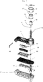
- FIGS. 7 to 10 are an exploded view, cross-sectional and longitudinal sectional views and a top view of an antitheft device according to an alternative embodiment wherein one of the arms contains a cartridge (50) filled with a marking substance.
- This substance may be an indelible ink, possibly under pressure.
- the cartridge (50) breaks and releases its content on the protected article, thereby removing its value permanently, but also on the hands of the thief.
- the ink capsule (50) is transparent to allow visibility of the ink.
- the cartridge (50) may also contain an odorous substance, for example a foul-smelling liquid, facilitating the identification of the thief and the provision of a presumption of attempted theft.
- an odorous substance for example a foul-smelling liquid
- the cartridge (50) is transparent to sensitize people tempted to commit fraud of the consequences of their act. It is protected by a transparent blade (51) and rests on a cradle (52).
- the second arm (2) incorporates an electromagnetic element (52) interacting with the antenna of the detection gantries placed at the entrances and exits of the magazine.
- the two arms (1, 2) are articulated by an axis (54).
- the figure 11 represents another variant embodiment of an antitheft device for fabrics or clothing.
- the inner surfaces of the arms (1, 2) have complementary surface elements (55, 56) to enhance the holding of an article having a thin, deformable area such as a fabric or garment.
- These surface elements have protuberances (55) of geometry complementary to the geometry of the recesses (56) provided on the inner surface of the opposite arm.
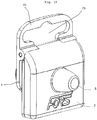
- FIGS 12 and 13 represent top views of a lock with a window (57) transparent and this lock protecting an article.
- the body of the lock can be either totally transparent or colored in the mass, with a window (57) passing through one of the arms (1) to allow the reading of information printed on the packaging (58) of the article to protect.
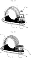
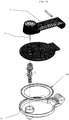
- FIGS. 14 and 15 represent top views of a lock for the protection of bottles.
- One of the arms (1) has an arcuate shape with a semicircular section, a radius corresponding to the outer radius of a bottle neck for example.
- the other arm (2) has a cradle (59) of a complementary profile. When the lock is closed, it determines a tubular space (60) can enclose a cylindrical portion of an article to protect.
- the various anti-theft devices can be grouped to form a set of locks, distinguished by a color code, for example by the color of the plastic or a colored pellet.
- FIGS. 16 to 18 represent views of another variant of implementation of the invention respectively from the front, in the open position, and from the rear, for securing against theft of articles presented under plastic shells with a top portion having a slot for hanging on the rods of a display.
- the device consists of two parts (1, 2) of rectangular shape, connected by an axis (53).
- One of the parts (1) is provided with the retractable elements (12 to 14) for the displacement of the needle (4) between the retracted position, where its end is set back with respect to the inner surface of the part ( 1), and a locking position where it passes through the blister of the article and enters the locking member (5) through a hole (72) provided in the second part (2).
- the inner surfaces of the rectangular portions (1, 2) have complementary zones (71) for blocking the fastening slot of the blisters.
- the upper part of the device has an area (70) provided with a slot (73) having the general shape of the attachment cutout provided with the blisters.
- the blister is introduced when the two parts (1, 2) are open and the needle (4) retracted.
- the clipping slit of the blister is then positioned in the complementary zone (71), and the two parts (1, 2) are closed.
- the needle (4) is then pressed by pressing on the retractable parts (12 to 14) until the end of the needle is inserted into the ball lock system (5).
- FIGS. 19 to 22 represent views of another variant embodiment of the invention, with an indexed coding.
- This variant makes it possible to highlight an encoding related to the value of the secure object. Indeed thieves replace the barcode label on the bottle by a barcode label of a bottle of a lower price. This flight tip is very difficult to track in the box, a secure marking bottle by a barcode label of a bottle of a lower price. This trick flight is very difficult to detect in cash, a secure marking on the lock associating a number (s) or letter (s) in relation to the value of the object (example: coding 1 -> price between 1 and 10 EUROS / coding 2 - price between 10 and 20 EUROS etc ...) allows the cashier to have an immediate relationship between the actual value of the bottle and the price related to the barcode. If the bottle goes to 9 euros and the coding is 4 (price between 30 and 40 euro).
- the upper movable body must be necessarily transparent.
- the knob and the coding ring being free to rotate, we have the possibility when the device is unlocked to be able to freely manipulate (in rotation) the coding ring. Depending on the desired coding, turn the ring until the marking is vertical to the coding window.
- This example relates to an anti-theft device for bottles, but the proposed solution is not limited to this application, but more generally applies to any application of a needle lock operable by retractable cages.
- the portion (1) is transparent to avoid the masking of the capsule surrounding the neck of the bottle.
- This variant relates to the fact that the tubular wall of the outer cage (12) has a cutout (90) extending in the example described over an angular width of about 40 degrees.
- the intermediate cage (13) carries markings distributed on the outer surface of the tubular wall, in the example describes a series of numbers, characters, signs or colors.
- the marking made on this ring can in particular give an indication of the size of a garment by combining the lettering S / M / L / X / XL / XXL, or tariff range, or promotion.
- the intermediate cage When the device is in the open position, the intermediate cage can be moved angularly to match one of the markings of the intermediate cage with the cutout (90) of the outer cage.
- the lower front surface (91) of the intermediate cage (14), and more precisely of its annular edge, has one or more indexing teeth (92). These indexing teeth (92) cooperate with a notched surface (93) provided on an annular zone of the floor of the portion (1).
- the outer cage (12) has a slotted tubular skirt, forming tabs (94 to 96) whose lower end is provided with hooks (97 to 99).
- This part (1) has a housing whose tubular skirt has ribs (101) whose bottom has slots (100). The outer cage (12) is thus clipped into the part (1).
- the figure 23 another variant of an anti-theft device an indexing wheel.
- the operator moves the wheel (110) by turning it to reach the requested size.
- This wheel is an integral part of the upper mobile subassembly (1), having a window (112) cut to allow reading of one of the marks affixed to the wheel (110).
- a system of serrations (111) between the rotatable part and its housing prevents the wheel from turning unexpectedly.
- the figure 24 is an exploded view of another alternative embodiment of a lock for the protection of hanging articles, packaged in the form of "blister" (trade name).
- This variant has two parts (1, 2), one of which is provided with a tilting hook (120) in order to be able to exit the spindle more easily and without risk of breaking the hook.
- the articulation of the hook (120) also prevents it from producing a lever effect that can weaken the device.
- This hook (120) is hinged relative to the portion (1) with two pivots (121, 122) also ensuring the articulation between the first and the second portion (1, 2).
- the device has on the inner surface of one of the parts (2), two retractable pins (123, 124) mounted on springs (125, 126). These pins (123, 124) make it possible to set up blisters having hook holes of different shapes and thicknesses and to adapt the size of the cavity formed between the two parts to the configuration of the article to be protected. without unnecessary game.
- the shape of the standard hook allowed the passage of three pawns, which is not the case for other forms of hooked (round hole or triangular).
- the retractable side pegs (123, 124) allow positioning of a wide variety of hook shapes.
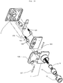
- FIGS. 25 to 28 represent views of another alternative embodiment of the invention, for the protection of articles such as shoes, lingerie articles, articles having a closed tube, etc.
- one of the parts (2) has a housing (131) receiving the end of a loop (130) made of a material resistant to cutting, including a steel buckle.
- the opposite end of this loop (130) has a bore (132) which can be traversed by the needle (4).
- This device uses the same locking base as the other variants, and allows you to adapt the lock with a minimum of technical changes to the protection of a wide range of items.
- the loop may have a "U" shape as shown in the Figures 25 and 26 , or even more elaborate forms, as represented in figure 27 and 28 , for example a shape with a loop (133) of reduced width extended by a bridge (134).
- FIGS. 29 to 30 represent views of another variant of implementation of the invention with enhanced security, respectively represented in the locked position and in the unlocked position.
- the vertical subassembly consisting of the main feeder (135), the ball cage (136) and the balls ( 137, 138) can not descend under the action of the lower magnet (139). The descent of this subassembly releases the pressure exerted on the nail by the balls (137, 138).
- the number of lateral weights can be set between 1 and N, and a regular distribution or not to enhance security.
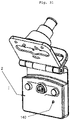
- the figure 31 represents a view of an alternative embodiment of a lock with an alarm.
- One of the parts (2) contains an electronic circuit integrated in the body, with a power supply and a sound generator.
- a probe (140) detects the closure of the device and the support of a protected article between the two parts (1, 2). The activation of the alarm is done when the device is closed. In the open position, it is in standby, until a first closing, activating the alarm. In case of forcing of the opening, the probe (140) is released and triggers the alarm.
- the deactivation under the control of the hostess is carried out by the detection of a magnetic field or a remote deactivation means.
- This circuit would be equipped with a probe allowing that during the introduction of the blister, the pressure exerted by the closure of the moving part and the blister activates the alarm via the probe. During the attempted break-in either by tearing off the blister or attempting to tear off the nail the probe is released and triggers the alarm
- the figure 31 shows a view of another alternative embodiment of a lock with an annular coil (150).
- One of the parts (2) has a disc shape, to receive a large annular coil (150), to increase the efficiency of the detection.
- the invention also relates to an anti-theft system constituted by a plurality of devices according to claim 1 and comprising a locking system common to a range of products, and a plurality of components forming variable first and second parts of geometry.
- the locking system is constituted by a first assembly comprising the nestable cages (12 to 14) and the nail (4), and a second assembly constituted by the locking system of the nail by balls.
- the first set may consist of a clipping component on one of the parts.
- the second set may also consist of a clip-on component on the opposite side.
- This solution reduces tooling costs to provide a wide range of anti-theft products.
Landscapes
- Physics & Mathematics (AREA)
- Engineering & Computer Science (AREA)
- Automation & Control Theory (AREA)
- Computer Security & Cryptography (AREA)
- Electromagnetism (AREA)
- General Physics & Mathematics (AREA)
- Multimedia (AREA)
- Burglar Alarm Systems (AREA)
Claims (21)
- Diebstahlsicherung, die dazu bestimmt ist, an einem freiverkäuflichen Artikel befestigt zu werden, und aus zwei Teilen (1, 2) besteht, von denen einer ein Mittel zum wechselseitigen Zusammenwirken mit einer Säule zur Detektion des Durchgangs einer solchen Sicherung umfasst, wobei besagte Teile (1,2) durch ein Scharnier (3) gelenkig verbunden sind, um das Schwingen zwischen einer gesicherten Position, in welcher sie mit einem Teil des zu sichernden Artikels zusammenwirken, um das Lösen der Diebstahlssicherung vom Artikel zu verhindern, und einer Freigabeposition, in welcher sie die Abnahme vom Artikel zulassen, zu ermöglichen, wobei einer der beiden Teile (1) am entgegengesetzten Ende des besagten beweglichen Gelenks (3) eine Nadel (4) aufweist, die in einer Richtung senkrecht zur Mittelebene der Sicherung beweglich ist, und der andere Teil (2) eine Aufnahme (5) umfasst, um besagte Nadel (4) aufzunehmen, wobei die Aufnahme (5) Verriegelungsmittel umfasst, die so gestaltet sind, dass besagte Nadel (4) mithilfe einer Entriegelungsvorrichtung freigegeben werden kann, dadurch gekennzeichnet, dass besagter erster Teil (1) drei einfahrbare Hülsen, genannt äußere Hülse, mittlere Hülse und innere Hülse (12, 13, 14,), aufweist, die die Bewegung der besagten Nadel (4) zwischen einer eingefahrenen Position, in der die Spitze der besagten Nadel (4) nicht über die Innenfläche des ersten Teils hinausragt, und einer ausgefahrenen Position, in welcher die besagte Nadel (4) bei geschlossener Sicherung in der zusätzlichen Aufnahme (5) aufliegt, ermöglichen.
- Diebstahlssicherung nach dem vorhergehenden Anspruch, dadurch gekennzeichnet, dass die äußere Hülse (12) einen Innenhohlraum aufweist, welcher dem äußeren Volumen der mittleren Hülse (13) entspricht, wobei besagte mittlere Hülse (13) einen Innenhohlraum aufweist, der dem äußeren Volumen der inneren Hülse (14) entspricht, wobei die Höhe der mittleren Hülse (13) so gestaltet ist, dass sie nicht über die obere Stirnfläche der äußeren Hülse (12) hinausragt, wobei die Höhe der mittleren Hülse (14) so gestaltet ist, dass sie in verriegelter Position nicht über die obere Stirnhöhe der äußeren Hülse (12) und der mittleren Hülse (13) hinausragt.
- Diebstahlsicherung nach mindestens einem der vorhergehenden Ansprüche, dadurch gekennzeichnet, dass das Verriegelungsmittel aus mindestens einer Kugel (22, 23) besteht, die durch eine Feder (25) auf den Boden der Aufnahme (21), welche die Nadel (4) aufnehmen soll, zurückgedrückt wird, wobei besagte Aufnahme (21) eine Konusform aufweist, die bewirken soll, dass sich die Kugel an der Nadel verkeilt, wobei besagte Kugel mit einem Entriegelungsmittel zusammenwirken kann, um sich der Wirkung der besagten Feder entgegen zu setzen.
- Diebstahlsicherung nach mindestens einem der vorhergehenden Ansprüche, dadurch gekennzeichnet, dass das Verriegelungsmittel des Weiteren ein Mittel zur seitlichen Blockierung der besagten konusförmigen Aufnahme (21) enthält, wobei besagtes seitliches Blockierungsmittel mit einem Entriegelungsmittel zusammenwirken kann, um die axiale Verschiebung der besagten Aufnahme (21) freizugeben.
- Diebstahlsicherung nach mindestens einem der vorhergehenden Ansprüche, dadurch gekennzeichnet, dass einer der besagten Teile (1, 2) eine Kapsel enthält, die mit einer markierenden Substanz gefüllt ist.
- Diebstahlsicherung nach mindestens einem der vorhergehenden Ansprüche, dadurch gekennzeichnet, dass einer der besagten Teile (1, 2) mindestens einen transparenten Bereich aufweist.
- Diebstahlsicherung nach mindestens einem der vorhergehenden Ansprüche, dadurch gekennzeichnet, dass mindestens einer der besagten Teile (1, 2) an seiner Innenfläche einen Oberflächenzustand aufweist, der das mechanische Zusammenwirken mit dem zu sichernden Artikel verstärkt.
- Diebstahlsicherung nach mindestens einem der vorhergehenden Ansprüche, dadurch gekennzeichnet, dass besagte Teile (1, 2) an ihren Innenflächen zusätzliche Oberflächenelemente zur Verstärkung des Zusammenwirkens mit einem zu sichernden dünnen und verformbaren Artikel aufweisen.
- Diebstahlsicherung nach mindestens einem der vorhergehenden Ansprüche, dadurch gekennzeichnet, dass besagte Teile (1, 2) eine gebogene Form aufweisen, um einen zylindrischen Bereich eines zu sichernden Artikels zu umgeben.
- Diebstahlsicherung nach Anspruch 1, dadurch gekennzeichnet, dass sie aus zwei Teilen (1, 2) in rechteckiger Form besteht, die durch eine Achse (53) miteinander verbunden sind, wobei einer der Teile (1) durch einen Befestigungsbereich (73) verlängert wird, wobei einer der Teile (1) mit einfahrbaren Elementen (12 bis 14) zum Verschieben der Nadel (4) zwischen der eingefahrenen Position, in welcher ihr Ende in Bezug auf die Innenfläche des Teils (1) versenkt ist, und einer Verriegelungsposition, in welcher sie durch den Befestigungsausschnitt des Blisters des Artikels in das Verriegelungselement (5) durch ein im zweiten Teil (2) vorgesehenes Loch (72) geführt wird, versehen ist.
- Diebstahlsicherung nach mindestens einem der vorhergehenden Ansprüche, dadurch gekennzeichnet, dass sie eines der Elemente einer Reihe von Diebstahlsicherungen bildet, die sich durch einen Farbcode voneinander unterscheiden.
- Diebstahlsicherung nach mindestens einem der vorhergehenden Ansprüche, dadurch gekennzeichnet, dass die untere Stirnfläche (91) der mittleren Hülse (14) einen oder mehrere Zähne (92) zur Indexierung aufweist, die mit einer gezahnten Oberfläche (93) auf einem ringförmigen Bereich der Bodenfläche von Teil (1) zusammenwirken können.
- Diebstahlsicherung nach mindestens einem der vorhergehenden Ansprüche, dadurch gekennzeichnet, dass die rohrförmige Wandung der äußeren Hülse (12) einen Ausschnitt (90) aufweist, und dadurch, dass die mittlere Hülse (13) Kennzeichnungen aufweist, die auf der äußeren Fläche der rohrförmigen Wandung verteilt sind.
- Diebstahlsicherung nach mindesten einem der vorhergehenden Ansprüche, dadurch gekennzeichnet, dass die äußere Hülse (12) einen rohrförmigen geschlitzten Rand aufweist, welcher Ansätze (94 bis 96) bildet, deren inneres Ende mit Haken (97 bis 99) versehen ist, die die Befestigung der äußeren Hülse (12) an dem Teil (1) mit den Aufnahmen gewährleistet, deren röhrenförmiger Rand Rippen (101) aufweist, die mit Schlitzen (100) zum Anklippen der äußeren Hülse (12) versehen sind.
- Diebstahlsicherung nach mindestens einem der vorhergehenden Ansprüche, dadurch gekennzeichnet, dass sie ein Rädchen (110) umfasst, das in einem der Teile (1) aufgenommen ist, welcher ein ausgeschnittenes Fenster (112) aufweist, um das Lesen einer der auf dem Rädchen (110) aufgebrachten Markierungen zu ermöglichen.
- Diebstahlsicherung nach mindestens einem der vorhergehenden Ansprüche, dadurch gekennzeichnet, dass einer der Teile (1) auf seiner Innenfläche mindestens einen einziehbaren Zapfen (123, 124) aufweist, der auf Federn (125, 126) montiert ist.
- Diebstahlsicherung nach mindestens einem der vorhergehenden Ansprüche, dadurch gekennzeichnet, dass einer der Teile (2) eine Aufnahme (131) aufweist, welche das Ende einer Schlaufe (130) aufnimmt, wobei das entgegengesetzte Ende dieser Schlaufe (130) eine Bohrung (132) aufweist, durch welche die Nadel (4) geführt werden kann.
- Diebstahlsicherung nach mindestens einen der vorhergehenden Ansprüche, dadurch gekennzeichnet, dass das Verriegelungsmittel mindestens ein seitliches Gewicht (130, 131) umfasst, das von dem seitlichen Magneten (133, 134) angezogen werden kann, und in Ruhestellung die Verschiebung der senkrechten Teilgruppe bestehend aus dem Hauptgewicht (135) blockiert.
- Diebstahlsicherung nach mindestens einem der vorhergehenden Ansprüche, dadurch gekennzeichnet, dass einer der Teile (2) einen in den Körper eingebauten elektronischen Kreis enthält mit einer Stromversorgung und einem Tongenerator. Ein Taster (140) erkennt das Schließen der Vorrichtung und das Aufliegen eines gesicherten Artikels zwischen den beiden Teilen (1, 2).
- Diebstahlsicherung nach mindestens einem der vorhergehenden Ansprüche, dadurch gekennzeichnet, dass einer der Teile (2) scheibenförmig ist, um eine ringförmige Spule (150) mit großen Abmessungen aufzunehmen.
- Diebstahlsicherungssystem bestehend aus einer Vielzahl an Vorrichtungen gemäß Anspruch 1, dadurch gekennzeichnet, dass es ein Verriegelungssystem aufweist, das einer Produktreihe gemeinsam ist, und eine Vielzahl an Komponenten, welche die ersten und die zweiten Teile veränderlicher Geometrie bilden, wobei jede der besagten Verriegelungsvorrichtungen aus einer ersten Baugruppe besteht, welche die ineinander steckenden Hülsen (12 bis 14) und die Nadel (4) umfassen, und einer zweiten Baugruppe, die aus dem Blockiersystem besteht, bei welchem die Nadel durch die Kugeln blockiert wird.
Priority Applications (1)
| Application Number | Priority Date | Filing Date | Title |
|---|---|---|---|
| PL14738569T PL3014038T3 (pl) | 2013-06-28 | 2014-06-20 | Urządzenie zapobiegające kradzieży przeznaczone do zamocowania na towarze w wolnej sprzedaży |
Applications Claiming Priority (3)
| Application Number | Priority Date | Filing Date | Title |
|---|---|---|---|
| FR1356327A FR3007783B1 (fr) | 2013-06-28 | 2013-06-28 | Dispositif antivol destine a etre attache a un article en vente libre |
| FR1451287A FR3007784B1 (fr) | 2013-06-28 | 2014-02-18 | Dispositif antivol destine a etre attache a un article en vente libre |
| PCT/FR2014/051552 WO2014207356A1 (fr) | 2013-06-28 | 2014-06-20 | Dispositif antivol destiné a être attaché a un article en vente libre |
Publications (2)
| Publication Number | Publication Date |
|---|---|
| EP3014038A1 EP3014038A1 (de) | 2016-05-04 |
| EP3014038B1 true EP3014038B1 (de) | 2018-12-26 |
Family
ID=48980192
Family Applications (1)
| Application Number | Title | Priority Date | Filing Date |
|---|---|---|---|
| EP14738569.4A Active EP3014038B1 (de) | 2013-06-28 | 2014-06-20 | Diebstahlsichere vorrichtung zur anbringung an einem ladenverkaufsgegenstand |
Country Status (7)
| Country | Link |
|---|---|
| US (1) | US9790715B2 (de) |
| EP (1) | EP3014038B1 (de) |
| CN (1) | CN205259744U (de) |
| ES (1) | ES2711698T3 (de) |
| FR (2) | FR3007783B1 (de) |
| PL (1) | PL3014038T3 (de) |
| WO (1) | WO2014207356A1 (de) |
Cited By (2)
| Publication number | Priority date | Publication date | Assignee | Title |
|---|---|---|---|---|
| FR3112803A1 (fr) | 2020-07-24 | 2022-01-28 | Fors France | Dispositif antivol destiné à être attaché à un article en vente libre |
| FR3140004A1 (fr) | 2022-09-27 | 2024-03-29 | Fors France | Dispositif antivol pour outils munis d’une queue a emmanchement |
Families Citing this family (22)
| Publication number | Priority date | Publication date | Assignee | Title |
|---|---|---|---|---|
| US9637951B2 (en) * | 2014-10-10 | 2017-05-02 | Tyco Fire & Security Gmbh | Security tag |
| EP3256673B1 (de) * | 2015-02-13 | 2020-09-30 | Necchi, Piero | Diebstahlsichere vorrichtung mit schutz vor verletzungen |
| US10121342B2 (en) * | 2016-12-07 | 2018-11-06 | Tyco Fire & Security Gmbh | Security tag with stain prevention pads |
| US10301852B2 (en) * | 2017-04-06 | 2019-05-28 | Checkpoint Systems, Inc. | Product security device with engagement pin |
| US11913257B2 (en) | 2017-04-06 | 2024-02-27 | Checkpoint Systems, Inc. | Product security device with engagement pin |
| US10676968B2 (en) * | 2017-05-18 | 2020-06-09 | Sensormatic Electronics, LLC | Systems and methods for providing a security tag with a telescoping actuator and/or adjustable range of insert space sizes |
| CN107452176B (zh) * | 2017-10-10 | 2022-11-18 | 徐州龙安电子科技有限公司 | 一种防盗标签 |
| FR3078092A1 (fr) | 2018-02-22 | 2019-08-23 | Fors France | Systeme antivol destine a la protection d'un article conditionne sous emballage-coque |
| FR3086684B1 (fr) | 2018-10-02 | 2022-04-29 | Fors France | Dispositif antivol |
| USD876265S1 (en) * | 2018-10-09 | 2020-02-25 | Fors France | Anti-theft locking device |
| HUP1800372A1 (hu) * | 2018-11-05 | 2020-05-28 | Shopguard Kft | Termékre rögzíthetõ áruvédelmi címke |
| WO2020146653A1 (en) | 2019-01-11 | 2020-07-16 | Sensormatic Electronics, LLC | Systems and methods for operating a security tag |
| DE102019204779A1 (de) * | 2019-04-03 | 2020-10-08 | Rapitag Gmbh | Warendiebstahlsicherung, insbesondere für Textilprodukte |
| US11725425B2 (en) * | 2019-07-08 | 2023-08-15 | Sensormatic Electronics, LLC | Security tag with 3-ball clutch and rotation-driven release |
| CN110363948B (zh) * | 2019-08-22 | 2024-05-17 | 江苏傲讯达电子科技有限公司 | 一种防盗磁扣装置 |
| USD962806S1 (en) | 2020-08-26 | 2022-09-06 | Sensormatic Electronics, LLC | Security tag |
| GB2604105B (en) * | 2021-02-18 | 2023-03-29 | Sekura Global Ip Llp | Security tag |
| FR3120465B1 (fr) * | 2021-03-03 | 2023-10-13 | Thoonsen Trading | Dispositif antivol electronique ameliore |
| WO2022226136A1 (en) * | 2021-04-23 | 2022-10-27 | Checkpoint Systems, Inc. | Dual stage security tag |
| USD1002415S1 (en) * | 2021-07-29 | 2023-10-24 | Prosegur EAS USA, LLC | Electronic surveillance tag for clothing, textiles, fabric articles and the like |
| GB2619329A (en) * | 2022-06-01 | 2023-12-06 | Sekura Global Ip Llp | Retail security assembly |
| US20230407673A1 (en) * | 2022-06-20 | 2023-12-21 | Yondr, Inc. | Lock with Integrated Engagement Indicator |
Family Cites Families (19)
| Publication number | Priority date | Publication date | Assignee | Title |
|---|---|---|---|---|
| US4221025A (en) * | 1978-12-20 | 1980-09-09 | I. D. Engineering, Inc. | Anti-theft locking device |
| FR2509494A1 (fr) * | 1981-07-10 | 1983-01-14 | Gresset Rene | Detecteur de protection contre le vol d'articles |
| US4670950A (en) * | 1985-05-13 | 1987-06-09 | Monarch Marking Systems, Inc. | Theft-deterrent tag |
| NL8900461A (nl) * | 1989-02-24 | 1990-09-17 | Nedap Nv | Wafer met bevestigingsbeugel. |
| US5019801A (en) * | 1989-07-24 | 1991-05-28 | Identitech | Article surveillance system having target removal sensor |
| US5022244A (en) * | 1990-05-29 | 1991-06-11 | Security Tag Systems, Inc. | Pin-clutch mechanism for theft-deterrent device |
| US5054172A (en) * | 1990-10-24 | 1991-10-08 | Security Tag Systems, Inc. | Expulsion of detrimental substance from theft-deterrent device |
| DE4432644A1 (de) | 1994-09-14 | 1996-03-21 | Hoechst Ag | Ungesättigte Polyesterurethanacrylate als Bindemittel für Pulverlacke |
| US6255950B1 (en) * | 1999-10-19 | 2001-07-03 | Sensormatic Electronics Corporation | Tack assembly for electronic article surveillance tags |
| US6449991B1 (en) * | 2000-04-12 | 2002-09-17 | Sensormatic Electronics Corporation | One part theft deterrent device |
| US7190272B2 (en) * | 2003-05-06 | 2007-03-13 | Xiao Hui Yang | EAS tag with ball clutch |
| US20060070410A1 (en) * | 2003-08-29 | 2006-04-06 | Arthur Fuss | Product anti-theft device |
| US7342495B2 (en) * | 2004-06-02 | 2008-03-11 | Sayegh Adel O | Integrated theft deterrent device |
| EP1869275B1 (de) * | 2005-04-05 | 2008-10-15 | Pietro Necchi | Diebstahlsicherungsanhänger |
| US20070152836A1 (en) * | 2005-12-29 | 2007-07-05 | Alpha Security Products, Inc. | Theft deterrent device with onboard alarm |
| JP4134205B2 (ja) * | 2006-05-19 | 2008-08-20 | 株式会社和真 | 保持具 |
| FR2947086B1 (fr) * | 2009-06-18 | 2012-05-11 | Exaqtworld | Dispositif de marquage d'un article en vue de son identification |
| FR2951570B1 (fr) * | 2009-10-19 | 2012-06-29 | Thoonsen Trading | Dispositif antivol pour articles de vente |
| IT1401570B1 (it) * | 2010-08-12 | 2013-07-26 | Technology Tags S R L | Dispositivo antitaccheggio del tipo a chiodo e placca ferma chiodo |
-
2013
- 2013-06-28 FR FR1356327A patent/FR3007783B1/fr active Active
-
2014
- 2014-02-18 FR FR1451287A patent/FR3007784B1/fr active Active
- 2014-06-20 WO PCT/FR2014/051552 patent/WO2014207356A1/fr active Application Filing
- 2014-06-20 ES ES14738569T patent/ES2711698T3/es active Active
- 2014-06-20 PL PL14738569T patent/PL3014038T3/pl unknown
- 2014-06-20 US US14/900,201 patent/US9790715B2/en active Active
- 2014-06-20 CN CN201490000231.6U patent/CN205259744U/zh not_active Expired - Lifetime
- 2014-06-20 EP EP14738569.4A patent/EP3014038B1/de active Active
Non-Patent Citations (1)
| Title |
|---|
| None * |
Cited By (3)
| Publication number | Priority date | Publication date | Assignee | Title |
|---|---|---|---|---|
| FR3112803A1 (fr) | 2020-07-24 | 2022-01-28 | Fors France | Dispositif antivol destiné à être attaché à un article en vente libre |
| FR3140004A1 (fr) | 2022-09-27 | 2024-03-29 | Fors France | Dispositif antivol pour outils munis d’une queue a emmanchement |
| WO2024068175A1 (fr) | 2022-09-27 | 2024-04-04 | Fors France | Dispositif antivol pour outils munis d'une queue a emmanchement |
Also Published As
| Publication number | Publication date |
|---|---|
| US20160258192A1 (en) | 2016-09-08 |
| FR3007783B1 (fr) | 2015-07-10 |
| FR3007783A1 (fr) | 2015-01-02 |
| EP3014038A1 (de) | 2016-05-04 |
| US9790715B2 (en) | 2017-10-17 |
| FR3007784A1 (fr) | 2015-01-02 |
| CN205259744U (zh) | 2016-05-25 |
| FR3007784B1 (fr) | 2015-12-04 |
| ES2711698T3 (es) | 2019-05-06 |
| PL3014038T3 (pl) | 2019-07-31 |
| WO2014207356A1 (fr) | 2014-12-31 |
Similar Documents
| Publication | Publication Date | Title |
|---|---|---|
| EP3014038B1 (de) | Diebstahlsichere vorrichtung zur anbringung an einem ladenverkaufsgegenstand | |
| FR2944307A1 (fr) | Dispositif antivol pour articles de vente | |
| FR2702353A1 (fr) | Dispositif antivol pour lunettes. | |
| EP3025323B1 (de) | Kennzeichnungsvorrichtung mit einem haken für einen handelsartikel | |
| EP2491212B1 (de) | Diebstahlsicherungsvorrichtung für handelsartikel | |
| EP3469174B1 (de) | Diebstahlsicherung für dosen, konserven oder flaschen | |
| EP2526533B1 (de) | Diebstahlschutzeinheit für einen verkaufsartikel | |
| EP3102760B1 (de) | Diebstahlsichere vorrichtung zur befestigung an einem artikel zum verkauf | |
| WO2019162588A1 (fr) | Systeme antivol destine a la protection d'un article conditionne sous emballage-coque | |
| EP2734695B1 (de) | Anordnung zum schutz eines temporär zusammensetzbaren handelsartikels gegen diebstahl | |
| EP0278811B1 (de) | Kleiderbügel für das Ausstellen von Textilwaren | |
| EP3861187B1 (de) | Antidiebstahlvorrichtung | |
| EP2489818B1 (de) | Diebstahlsicherungsvorrichtung mit verbesserter Sicherheitsklemmbacke | |
| WO2002031299A1 (fr) | Equipment antivol | |
| WO2008056058A2 (fr) | Dispositif de securite pour detecter une manipulation frauduleuse sur un article à protéger | |
| WO2010052391A1 (fr) | Systeme de protection anti-vol comprenant un boîtier longiligne et un dispositif de fermeture | |
| WO2004013436A2 (fr) | Dispositif et procede antivol pour articles comportant au moins une extremite ou une section de forme sensiblement cylindrique | |
| FR2843154A1 (fr) | Dispositif et procede antivol pour articles comportant au moins une extremite ou une section de forme sensiblement cylindrique | |
| FR2733784A3 (fr) | Boitier antivol pour proteger contre le risque de vol des articles exposes a la vente |
Legal Events
| Date | Code | Title | Description |
|---|---|---|---|
| PUAI | Public reference made under article 153(3) epc to a published international application that has entered the european phase |
Free format text: ORIGINAL CODE: 0009012 |
|
| 17P | Request for examination filed |
Effective date: 20151221 |
|
| AK | Designated contracting states |
Kind code of ref document: A1 Designated state(s): AL AT BE BG CH CY CZ DE DK EE ES FI FR GB GR HR HU IE IS IT LI LT LU LV MC MK MT NL NO PL PT RO RS SE SI SK SM TR |
|
| AX | Request for extension of the european patent |
Extension state: BA ME |
|
| DAX | Request for extension of the european patent (deleted) | ||
| STAA | Information on the status of an ep patent application or granted ep patent |
Free format text: STATUS: EXAMINATION IS IN PROGRESS |
|
| 17Q | First examination report despatched |
Effective date: 20180531 |
|
| GRAP | Despatch of communication of intention to grant a patent |
Free format text: ORIGINAL CODE: EPIDOSNIGR1 |
|
| STAA | Information on the status of an ep patent application or granted ep patent |
Free format text: STATUS: GRANT OF PATENT IS INTENDED |
|
| INTG | Intention to grant announced |
Effective date: 20181004 |
|
| GRAS | Grant fee paid |
Free format text: ORIGINAL CODE: EPIDOSNIGR3 |
|
| GRAA | (expected) grant |
Free format text: ORIGINAL CODE: 0009210 |
|
| STAA | Information on the status of an ep patent application or granted ep patent |
Free format text: STATUS: THE PATENT HAS BEEN GRANTED |
|
| AK | Designated contracting states |
Kind code of ref document: B1 Designated state(s): AL AT BE BG CH CY CZ DE DK EE ES FI FR GB GR HR HU IE IS IT LI LT LU LV MC MK MT NL NO PL PT RO RS SE SI SK SM TR |
|
| REG | Reference to a national code |
Ref country code: GB Ref legal event code: FG4D Free format text: NOT ENGLISH |
|
| REG | Reference to a national code |
Ref country code: CH Ref legal event code: EP |
|
| REG | Reference to a national code |
Ref country code: AT Ref legal event code: REF Ref document number: 1081634 Country of ref document: AT Kind code of ref document: T Effective date: 20190115 |
|
| REG | Reference to a national code |
Ref country code: DE Ref legal event code: R096 Ref document number: 602014038617 Country of ref document: DE |
|
| REG | Reference to a national code |
Ref country code: IE Ref legal event code: FG4D Free format text: LANGUAGE OF EP DOCUMENT: FRENCH |
|
| REG | Reference to a national code |
Ref country code: NL Ref legal event code: FP |
|
| PG25 | Lapsed in a contracting state [announced via postgrant information from national office to epo] |
Ref country code: FI Free format text: LAPSE BECAUSE OF FAILURE TO SUBMIT A TRANSLATION OF THE DESCRIPTION OR TO PAY THE FEE WITHIN THE PRESCRIBED TIME-LIMIT Effective date: 20181226 Ref country code: BG Free format text: LAPSE BECAUSE OF FAILURE TO SUBMIT A TRANSLATION OF THE DESCRIPTION OR TO PAY THE FEE WITHIN THE PRESCRIBED TIME-LIMIT Effective date: 20190326 Ref country code: HR Free format text: LAPSE BECAUSE OF FAILURE TO SUBMIT A TRANSLATION OF THE DESCRIPTION OR TO PAY THE FEE WITHIN THE PRESCRIBED TIME-LIMIT Effective date: 20181226 Ref country code: LV Free format text: LAPSE BECAUSE OF FAILURE TO SUBMIT A TRANSLATION OF THE DESCRIPTION OR TO PAY THE FEE WITHIN THE PRESCRIBED TIME-LIMIT Effective date: 20181226 Ref country code: LT Free format text: LAPSE BECAUSE OF FAILURE TO SUBMIT A TRANSLATION OF THE DESCRIPTION OR TO PAY THE FEE WITHIN THE PRESCRIBED TIME-LIMIT Effective date: 20181226 Ref country code: NO Free format text: LAPSE BECAUSE OF FAILURE TO SUBMIT A TRANSLATION OF THE DESCRIPTION OR TO PAY THE FEE WITHIN THE PRESCRIBED TIME-LIMIT Effective date: 20190326 |
|
| REG | Reference to a national code |
Ref country code: ES Ref legal event code: FG2A Ref document number: 2711698 Country of ref document: ES Kind code of ref document: T3 Effective date: 20190506 |
|
| REG | Reference to a national code |
Ref country code: LT Ref legal event code: MG4D |
|
| PG25 | Lapsed in a contracting state [announced via postgrant information from national office to epo] |
Ref country code: RS Free format text: LAPSE BECAUSE OF FAILURE TO SUBMIT A TRANSLATION OF THE DESCRIPTION OR TO PAY THE FEE WITHIN THE PRESCRIBED TIME-LIMIT Effective date: 20181226 Ref country code: GR Free format text: LAPSE BECAUSE OF FAILURE TO SUBMIT A TRANSLATION OF THE DESCRIPTION OR TO PAY THE FEE WITHIN THE PRESCRIBED TIME-LIMIT Effective date: 20190327 Ref country code: AL Free format text: LAPSE BECAUSE OF FAILURE TO SUBMIT A TRANSLATION OF THE DESCRIPTION OR TO PAY THE FEE WITHIN THE PRESCRIBED TIME-LIMIT Effective date: 20181226 Ref country code: SE Free format text: LAPSE BECAUSE OF FAILURE TO SUBMIT A TRANSLATION OF THE DESCRIPTION OR TO PAY THE FEE WITHIN THE PRESCRIBED TIME-LIMIT Effective date: 20181226 |
|
| REG | Reference to a national code |
Ref country code: AT Ref legal event code: MK05 Ref document number: 1081634 Country of ref document: AT Kind code of ref document: T Effective date: 20181226 |
|
| PG25 | Lapsed in a contracting state [announced via postgrant information from national office to epo] |
Ref country code: PT Free format text: LAPSE BECAUSE OF FAILURE TO SUBMIT A TRANSLATION OF THE DESCRIPTION OR TO PAY THE FEE WITHIN THE PRESCRIBED TIME-LIMIT Effective date: 20190426 Ref country code: CZ Free format text: LAPSE BECAUSE OF FAILURE TO SUBMIT A TRANSLATION OF THE DESCRIPTION OR TO PAY THE FEE WITHIN THE PRESCRIBED TIME-LIMIT Effective date: 20181226 |
|
| PG25 | Lapsed in a contracting state [announced via postgrant information from national office to epo] |
Ref country code: EE Free format text: LAPSE BECAUSE OF FAILURE TO SUBMIT A TRANSLATION OF THE DESCRIPTION OR TO PAY THE FEE WITHIN THE PRESCRIBED TIME-LIMIT Effective date: 20181226 Ref country code: SM Free format text: LAPSE BECAUSE OF FAILURE TO SUBMIT A TRANSLATION OF THE DESCRIPTION OR TO PAY THE FEE WITHIN THE PRESCRIBED TIME-LIMIT Effective date: 20181226 Ref country code: SK Free format text: LAPSE BECAUSE OF FAILURE TO SUBMIT A TRANSLATION OF THE DESCRIPTION OR TO PAY THE FEE WITHIN THE PRESCRIBED TIME-LIMIT Effective date: 20181226 Ref country code: IS Free format text: LAPSE BECAUSE OF FAILURE TO SUBMIT A TRANSLATION OF THE DESCRIPTION OR TO PAY THE FEE WITHIN THE PRESCRIBED TIME-LIMIT Effective date: 20190426 Ref country code: RO Free format text: LAPSE BECAUSE OF FAILURE TO SUBMIT A TRANSLATION OF THE DESCRIPTION OR TO PAY THE FEE WITHIN THE PRESCRIBED TIME-LIMIT Effective date: 20181226 |
|
| REG | Reference to a national code |
Ref country code: DE Ref legal event code: R097 Ref document number: 602014038617 Country of ref document: DE |
|
| PG25 | Lapsed in a contracting state [announced via postgrant information from national office to epo] |
Ref country code: AT Free format text: LAPSE BECAUSE OF FAILURE TO SUBMIT A TRANSLATION OF THE DESCRIPTION OR TO PAY THE FEE WITHIN THE PRESCRIBED TIME-LIMIT Effective date: 20181226 Ref country code: DK Free format text: LAPSE BECAUSE OF FAILURE TO SUBMIT A TRANSLATION OF THE DESCRIPTION OR TO PAY THE FEE WITHIN THE PRESCRIBED TIME-LIMIT Effective date: 20181226 |
|
| PLBE | No opposition filed within time limit |
Free format text: ORIGINAL CODE: 0009261 |
|
| STAA | Information on the status of an ep patent application or granted ep patent |
Free format text: STATUS: NO OPPOSITION FILED WITHIN TIME LIMIT |
|
| 26N | No opposition filed |
Effective date: 20190927 |
|
| PG25 | Lapsed in a contracting state [announced via postgrant information from national office to epo] |
Ref country code: MC Free format text: LAPSE BECAUSE OF FAILURE TO SUBMIT A TRANSLATION OF THE DESCRIPTION OR TO PAY THE FEE WITHIN THE PRESCRIBED TIME-LIMIT Effective date: 20181226 |
|
| REG | Reference to a national code |
Ref country code: CH Ref legal event code: PL |
|
| PG25 | Lapsed in a contracting state [announced via postgrant information from national office to epo] |
Ref country code: SI Free format text: LAPSE BECAUSE OF FAILURE TO SUBMIT A TRANSLATION OF THE DESCRIPTION OR TO PAY THE FEE WITHIN THE PRESCRIBED TIME-LIMIT Effective date: 20181226 |
|
| REG | Reference to a national code |
Ref country code: BE Ref legal event code: MM Effective date: 20190630 |
|
| PG25 | Lapsed in a contracting state [announced via postgrant information from national office to epo] |
Ref country code: TR Free format text: LAPSE BECAUSE OF FAILURE TO SUBMIT A TRANSLATION OF THE DESCRIPTION OR TO PAY THE FEE WITHIN THE PRESCRIBED TIME-LIMIT Effective date: 20181226 |
|
| PG25 | Lapsed in a contracting state [announced via postgrant information from national office to epo] |
Ref country code: IE Free format text: LAPSE BECAUSE OF NON-PAYMENT OF DUE FEES Effective date: 20190620 |
|
| PG25 | Lapsed in a contracting state [announced via postgrant information from national office to epo] |
Ref country code: LU Free format text: LAPSE BECAUSE OF NON-PAYMENT OF DUE FEES Effective date: 20190620 Ref country code: BE Free format text: LAPSE BECAUSE OF NON-PAYMENT OF DUE FEES Effective date: 20190630 Ref country code: LI Free format text: LAPSE BECAUSE OF NON-PAYMENT OF DUE FEES Effective date: 20190630 Ref country code: CH Free format text: LAPSE BECAUSE OF NON-PAYMENT OF DUE FEES Effective date: 20190630 |
|
| PG25 | Lapsed in a contracting state [announced via postgrant information from national office to epo] |
Ref country code: CY Free format text: LAPSE BECAUSE OF FAILURE TO SUBMIT A TRANSLATION OF THE DESCRIPTION OR TO PAY THE FEE WITHIN THE PRESCRIBED TIME-LIMIT Effective date: 20181226 |
|
| PG25 | Lapsed in a contracting state [announced via postgrant information from national office to epo] |
Ref country code: MT Free format text: LAPSE BECAUSE OF FAILURE TO SUBMIT A TRANSLATION OF THE DESCRIPTION OR TO PAY THE FEE WITHIN THE PRESCRIBED TIME-LIMIT Effective date: 20181226 Ref country code: HU Free format text: LAPSE BECAUSE OF FAILURE TO SUBMIT A TRANSLATION OF THE DESCRIPTION OR TO PAY THE FEE WITHIN THE PRESCRIBED TIME-LIMIT; INVALID AB INITIO Effective date: 20140620 |
|
| PG25 | Lapsed in a contracting state [announced via postgrant information from national office to epo] |
Ref country code: MK Free format text: LAPSE BECAUSE OF FAILURE TO SUBMIT A TRANSLATION OF THE DESCRIPTION OR TO PAY THE FEE WITHIN THE PRESCRIBED TIME-LIMIT Effective date: 20181226 |
|
| PGFP | Annual fee paid to national office [announced via postgrant information from national office to epo] |
Ref country code: ES Payment date: 20230703 Year of fee payment: 10 |
|
| PGFP | Annual fee paid to national office [announced via postgrant information from national office to epo] |
Ref country code: NL Payment date: 20240521 Year of fee payment: 11 |
|
| PGFP | Annual fee paid to national office [announced via postgrant information from national office to epo] |
Ref country code: GB Payment date: 20240521 Year of fee payment: 11 |
|
| PGFP | Annual fee paid to national office [announced via postgrant information from national office to epo] |
Ref country code: DE Payment date: 20240521 Year of fee payment: 11 |
|
| PGFP | Annual fee paid to national office [announced via postgrant information from national office to epo] |
Ref country code: IT Payment date: 20240522 Year of fee payment: 11 Ref country code: FR Payment date: 20240521 Year of fee payment: 11 |
|
| PGFP | Annual fee paid to national office [announced via postgrant information from national office to epo] |
Ref country code: PL Payment date: 20240610 Year of fee payment: 11 |