EP3013394B1 - Einstellvorrichtung für einen durchflussregler - Google Patents
Einstellvorrichtung für einen durchflussregler Download PDFInfo
- Publication number
- EP3013394B1 EP3013394B1 EP14734093.9A EP14734093A EP3013394B1 EP 3013394 B1 EP3013394 B1 EP 3013394B1 EP 14734093 A EP14734093 A EP 14734093A EP 3013394 B1 EP3013394 B1 EP 3013394B1
- Authority
- EP
- European Patent Office
- Prior art keywords
- adjusting device
- setting disc
- setting
- adjusting
- disc
- Prior art date
- Legal status (The legal status is an assumption and is not a legal conclusion. Google has not performed a legal analysis and makes no representation as to the accuracy of the status listed.)
- Active
Links
Images

Classifications
-
- A—HUMAN NECESSITIES
- A61—MEDICAL OR VETERINARY SCIENCE; HYGIENE
- A61M—DEVICES FOR INTRODUCING MEDIA INTO, OR ONTO, THE BODY; DEVICES FOR TRANSDUCING BODY MEDIA OR FOR TAKING MEDIA FROM THE BODY; DEVICES FOR PRODUCING OR ENDING SLEEP OR STUPOR
- A61M5/00—Devices for bringing media into the body in a subcutaneous, intra-vascular or intramuscular way; Accessories therefor, e.g. filling or cleaning devices, arm-rests
- A61M5/14—Infusion devices, e.g. infusing by gravity; Blood infusion; Accessories therefor
- A61M5/168—Means for controlling media flow to the body or for metering media to the body, e.g. drip meters, counters ; Monitoring media flow to the body
- A61M5/16877—Adjusting flow; Devices for setting a flow rate
- A61M5/16881—Regulating valves
-
- A—HUMAN NECESSITIES
- A61—MEDICAL OR VETERINARY SCIENCE; HYGIENE
- A61M—DEVICES FOR INTRODUCING MEDIA INTO, OR ONTO, THE BODY; DEVICES FOR TRANSDUCING BODY MEDIA OR FOR TAKING MEDIA FROM THE BODY; DEVICES FOR PRODUCING OR ENDING SLEEP OR STUPOR
- A61M39/00—Tubes, tube connectors, tube couplings, valves, access sites or the like, specially adapted for medical use
- A61M39/22—Valves or arrangement of valves
- A61M39/28—Clamping means for squeezing flexible tubes, e.g. roller clamps
- A61M39/286—Wedge clamps, e.g. roller clamps with inclined guides
-
- A—HUMAN NECESSITIES
- A61—MEDICAL OR VETERINARY SCIENCE; HYGIENE
- A61M—DEVICES FOR INTRODUCING MEDIA INTO, OR ONTO, THE BODY; DEVICES FOR TRANSDUCING BODY MEDIA OR FOR TAKING MEDIA FROM THE BODY; DEVICES FOR PRODUCING OR ENDING SLEEP OR STUPOR
- A61M5/00—Devices for bringing media into the body in a subcutaneous, intra-vascular or intramuscular way; Accessories therefor, e.g. filling or cleaning devices, arm-rests
- A61M5/14—Infusion devices, e.g. infusing by gravity; Blood infusion; Accessories therefor
- A61M5/168—Means for controlling media flow to the body or for metering media to the body, e.g. drip meters, counters ; Monitoring media flow to the body
- A61M5/16877—Adjusting flow; Devices for setting a flow rate
-
- A—HUMAN NECESSITIES
- A61—MEDICAL OR VETERINARY SCIENCE; HYGIENE
- A61M—DEVICES FOR INTRODUCING MEDIA INTO, OR ONTO, THE BODY; DEVICES FOR TRANSDUCING BODY MEDIA OR FOR TAKING MEDIA FROM THE BODY; DEVICES FOR PRODUCING OR ENDING SLEEP OR STUPOR
- A61M5/00—Devices for bringing media into the body in a subcutaneous, intra-vascular or intramuscular way; Accessories therefor, e.g. filling or cleaning devices, arm-rests
- A61M5/178—Syringes
- A61M5/31—Details
- A61M5/315—Pistons; Piston-rods; Guiding, blocking or restricting the movement of the rod or piston; Appliances on the rod for facilitating dosing ; Dosing mechanisms
- A61M5/31533—Dosing mechanisms, i.e. setting a dose
- A61M5/31545—Setting modes for dosing
- A61M5/31548—Mechanically operated dose setting member
- A61M5/3155—Mechanically operated dose setting member by rotational movement of dose setting member, e.g. during setting or filling of a syringe
-
- A—HUMAN NECESSITIES
- A61—MEDICAL OR VETERINARY SCIENCE; HYGIENE
- A61M—DEVICES FOR INTRODUCING MEDIA INTO, OR ONTO, THE BODY; DEVICES FOR TRANSDUCING BODY MEDIA OR FOR TAKING MEDIA FROM THE BODY; DEVICES FOR PRODUCING OR ENDING SLEEP OR STUPOR
- A61M5/00—Devices for bringing media into the body in a subcutaneous, intra-vascular or intramuscular way; Accessories therefor, e.g. filling or cleaning devices, arm-rests
- A61M5/178—Syringes
- A61M5/31—Details
- A61M5/315—Pistons; Piston-rods; Guiding, blocking or restricting the movement of the rod or piston; Appliances on the rod for facilitating dosing ; Dosing mechanisms
- A61M5/31533—Dosing mechanisms, i.e. setting a dose
- A61M5/31545—Setting modes for dosing
- A61M5/31548—Mechanically operated dose setting member
- A61M5/3156—Mechanically operated dose setting member using volume steps only adjustable in discrete intervals, i.e. individually distinct intervals
-
- F—MECHANICAL ENGINEERING; LIGHTING; HEATING; WEAPONS; BLASTING
- F16—ENGINEERING ELEMENTS AND UNITS; GENERAL MEASURES FOR PRODUCING AND MAINTAINING EFFECTIVE FUNCTIONING OF MACHINES OR INSTALLATIONS; THERMAL INSULATION IN GENERAL
- F16K—VALVES; TAPS; COCKS; ACTUATING-FLOATS; DEVICES FOR VENTING OR AERATING
- F16K31/00—Actuating devices; Operating means; Releasing devices
- F16K31/44—Mechanical actuating means
- F16K31/60—Handles
-
- F—MECHANICAL ENGINEERING; LIGHTING; HEATING; WEAPONS; BLASTING
- F16—ENGINEERING ELEMENTS AND UNITS; GENERAL MEASURES FOR PRODUCING AND MAINTAINING EFFECTIVE FUNCTIONING OF MACHINES OR INSTALLATIONS; THERMAL INSULATION IN GENERAL
- F16K—VALVES; TAPS; COCKS; ACTUATING-FLOATS; DEVICES FOR VENTING OR AERATING
- F16K35/00—Means to prevent accidental or unauthorised actuation
- F16K35/04—Means to prevent accidental or unauthorised actuation yieldingly resisting the actuation
-
- A—HUMAN NECESSITIES
- A61—MEDICAL OR VETERINARY SCIENCE; HYGIENE
- A61M—DEVICES FOR INTRODUCING MEDIA INTO, OR ONTO, THE BODY; DEVICES FOR TRANSDUCING BODY MEDIA OR FOR TAKING MEDIA FROM THE BODY; DEVICES FOR PRODUCING OR ENDING SLEEP OR STUPOR
- A61M2205/00—General characteristics of the apparatus
- A61M2205/33—Controlling, regulating or measuring
- A61M2205/3331—Pressure; Flow
- A61M2205/3334—Measuring or controlling the flow rate
Definitions
- the invention relates to an adjustment device for adjusting the flow rate of a medical fluid delivery system.
- a medical fluid delivery system can, for example, be an infusion device for infusion therapy or for infusing a painkiller into a patient.
- Such fluid delivery systems require selecting and adjusting one of several possible flow rates for the fluid delivery.
- the flow rate at which the fluid is delivered must be adjusted with high precision and reliability. Incorrect adjustment, especially with infusion devices, can lead to over- or underdosing, which can have critical consequences for a patient.
- a dial is used to select one of several possible flow rates.
- a setting disc for setting the selected flow rate is permanently connected to the dial.
- a catch engages the radially outer edge of the setting disc. The engagement between the catch and the setting disc is such that the catch locks the setting disc and thus also the dial in the rotational position required to set the desired flow rate.
- the invention is based on the object of providing an improved adjustment device for adjusting the flow rate of a medical fluid delivery system.
- the adjusting device according to the invention is defined by the features of patent claim 1.
- the adjusting disc is therefore star-shaped.
- the star shape results in a rotationally symmetrical shape of the adjusting disc with a radially outer edge that has several areas with a maximum radius and several areas with a minimum radius.
- the areas of the radially outer Edges with maximum radius can be referred to as peaks and the areas with minimum radius as valleys.
- the star shape of the adjusting disc means that a valley and a peak alternate with one another.
- the interaction of the catch nose with the star shape of the adjusting disc leads to stable positions of the adjusting disc when the catch nose engages with a valley and to unstable positions when the catch nose engages with a peak.
- a peak does not have a constant radius, but rather a maximum radius that decreases towards the adjacent valley.
- the engagement of the catch nose with a peak leads to an unstable rotational position of the adjusting disc.
- the valleys serve as the rotational positions for setting a respective flow rate
- the peaks in between correspond to the rotational positions between adjacent rotational positions of adjustable flow rates. Inadvertently setting a rotational position between adjacent flow rates therefore leads to an unstable rotational position of the adjusting disc.
- a catch lug which is mounted against the force of a spring and pressed by the spring against the radially outer edge of the adjusting disc, will, when it rests against the radially outer edge between adjacent valleys, cause the spring force to rotate the adjusting disc from its unstable position, moving the catch lug into a valley and thus into a stable position.
- the catch lug is designed as a projection on a spiral spring, namely as a triangular projection with a tip.
- the star shape of the adjusting disc results in a zigzag shape of the radially outer edge, wherein adjacent lines of this zigzag shape are arranged inclined to one another at an angle between 10° and 155°, preferably between 90° and 135°.
- Fig. 1 shows a view of the adjustment device 10, in which the surface of the dial 12 is shown from the direction of its rotational axis. Along the radially outer edge of the dial 12, the numbers 0-7 are shown at equal intervals to mark the rotational positions corresponding to these numbers. Each of the numbers 0-7 corresponds to a possible adjustable flow rate, with 0 corresponding to no flow and 7 to maximum flow.
- the zigzag lines 18, 20 of the radially outer edge of the adjusting disc 14 are straight lines and arranged at shallow angles to one another in a range between approximately 110° and 130°. Adjacent zigzag lines 18, 20 form valleys 22 and peaks 24 at their points of contact. Each peak 24, as a radially outward-pointing vertex, forms a point with a maximum radius. Correspondingly, each valley 22, as a radially inward-pointing vertex, forms a point with a minimum radius. The radii of all valleys 22 are equal, and the radii of all peaks 24 are equal.
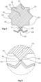
- a catch 26 engages with the zigzag lines 18, 20 of the star-shaped radial outer edge of the adjusting disc 14, which, as shown in the Figs. 3 - 5 is shown, is designed as a triangular tip of a spiral spring 28.
- the spiral spring 28 is a bent leaf spring. The spiral spring 28 is arranged with respect to the adjusting disc 14 in such a way that the spring force moves the catch nose 26 in the direction of the arrow 30 into the Fig. 3 and 4 radially inwards against the adjusting disc 14.
- Fig. 3 shows the stable position of the adjusting disc 14, in which the spring 28 presses the catch 26 into a valley 22 of the star shape.
- a force must be applied that counteracts the force that the spiral spring 28 exerts on the outer edge of the adjusting disc 14 via the catch 26.
- the adjusting disc 14 is always in an unstable position.
- Such an intermediate position is shown in the Figs. 4 and 5
- the star-shaped locking lug 26 presses diagonally against the edge of the adjusting disc 14 with the force of the spiral spring 28, causing the adjusting disc 14 to rotate until the locking lug comes to rest in one of the valleys 22. This prevents the setting of an intermediate position between adjacent valleys.
Landscapes
- Health & Medical Sciences (AREA)
- Engineering & Computer Science (AREA)
- Heart & Thoracic Surgery (AREA)
- Public Health (AREA)
- Anesthesiology (AREA)
- Hematology (AREA)
- Life Sciences & Earth Sciences (AREA)
- Animal Behavior & Ethology (AREA)
- General Health & Medical Sciences (AREA)
- Veterinary Medicine (AREA)
- Biomedical Technology (AREA)
- General Engineering & Computer Science (AREA)
- Vascular Medicine (AREA)
- Mechanical Engineering (AREA)
- Fluid Mechanics (AREA)
- Physics & Mathematics (AREA)
- Pulmonology (AREA)
- Infusion, Injection, And Reservoir Apparatuses (AREA)
- Transplanting Machines (AREA)
- Braking Arrangements (AREA)
Description
- Die Erfindung betrifft eine Einstellvorrichtung zum Einstellen der Flussrate eines medizinischen Fluidfördersystems.
- Ein medizinisches Fluidfördersystem kann beispielsweise ein Infusionsgerät zur Infusionstherapie oder zur Infusion eines Schmerzmittels in einen Patienten sein. Bei solchen Fluidfördersystemen ist es erforderlich, eine von mehreren möglichen Flussraten für die Fluidförderung auszuwählen und einzustellen. Die Einstellung der Flussrate, mit der das Fluid gefördert wird, muss mit hoher Genauigkeit und Sicherheit erfolgen. Eine Fehleinstellung kann vor allem bei Infusionsgeräten zu einer Über- oder Unterdosierung führen, die für einen Patienten kritische Auswirkungen haben kann.
- Es ist bekannt, die Einstellung der Flussrate mit Hilfe eines Drehreglers vorzunehmen. Dabei dient ein Wählrad zum Wählen einer von mehreren möglichen Flussraten. Mit dem Wählrad ist eine Stellscheibe zum Einstellen der gewählten Flussrate rotatorisch fest verbunden. Mit dem radial äußeren Rand der Stellscheibe wirkt dabei eine Fangnase zusammen. Der Eingriff zwischen der Fangnase und der Stellscheibe ist dabei derart, dass die Fangnase die Stellscheibe und somit auch das Wählrad in derjenigen Drehstellung arretiert, die zur Einstellung der gewünschten Flussrate erforderlich ist.
- Bei den bekannten Einstellvorrichtungen besteht eine Schwierigkeit darin, dass Zwischenstellungen zwischen benachbarten Drehstellungen entsprechender Flussraten eingestellt werden können, bei der weder die eine noch die andere Flussrate ausgewählt ist. Die versehentlich eingestellte Zwischenposition bleibt dabei eingestellt. Je nach Regulierungsmechanismus kann dies zu einer maximalen Förderung oder zu einer ausbleibenden Förderung des Fluids führen. Vor allem in der Infusionsmedizin kann dies kritische Folgen für einen Patienten haben.
- Aus der
EP 0 730 876 A ist eine Einstellvorrichtung mit den oberbegrifflichen Merkmalen des Anspruchs 1 bekannt. Bei der bekannten Einstellvorrichtung ist die Fangnase als flache dreieckige Spitze gestaltet, wobei der Spitzenwinkel der dreieckigen Spitze größer ist als der Winkel der Zickzacklinien der Stellscheibe. - Der Erfindung liegt die Aufgabe zugrunde, eine verbesserte Einstellvorrichtung zum Einstellen der Flussrate eines medizinischen Fluidfördersystems zu schaffen.
- Die erfindungsgemäße Einstellvorrichtung ist definiert durch die Merkmale von Patentanspruch 1. Die Stellscheibe ist demnach sternförmig ausgebildet. Die Sternform führt zu einer rotationssymetrischen Form der Stellscheibe mit einem radial äußeren Rand, der mehrere Bereiche mit maximalem Radius und mehrere Bereiche mit minimalem Radius aufweist. Die Bereiche des radial äußeren Randes mit maximalem Radius können als Gipfel und die Bereiche mit minimalem Radius als Täler bezeichnet werden. Die Sternform der Stellscheibe führt dazu, dass ein Tal und ein Gipfel einander abwechseln. Das Zusammenwirken der Fangnase mit der Sternform der Stellscheibe führt zu stabilen Lagen der Stellscheibe, wenn die Fangnase mit einem Tal zusammengreift und zu instabilen Lagen, wenn die Fangnase mit einem Gipfel zusammengreift. Dabei ist entscheidend, dass ein Gipfel keinen konstanten Radius aufweist, sondern einen maximalen Radius, der zum benachbarten Tal hin abnimmt. Dadurch führt das Angreifen der Fangnase an einem Gipfel zu einer instabilen Drehstellung der Stellscheibe. Während die Täler den Drehstellungen zur Einstellung einer jeweiligen Flussrate dienen, entsprechen die dazwischen liegenden Gipfel den Drehstellungen zwischen benachbarten Drehpositionen einstellbarer Flussraten. Ein versehentliches Einstellen einer Drehposition zwischen benachbarten Flussraten führt somit zu einer instabilen Drehposition der Stellscheibe.
- Eine Fangnase, die entgegen der Kraft einer Feder gelagert ist und von der Feder gegen den radial äußeren Rand der Stellscheibe gedrückt wird, wird bei Anliegen an dem radial äußeren Rand zwischen benachbarten Tälern dazu führen, dass die Federkraft die Stellscheibe aus ihrer instabilen Lage heraus in eine Drehung versetzt, um die Fangnase in ein Tal und somit in eine stabile Position zu bewegen. Erfindungsgemäß ist die Fangnase als Vorsprung an einer Biegefeder ausgebildet, nämlich als dreieckförmiger Vorsprung mit einer Spitze.
- Die Sternform der Stellscheibe ergibt gemäß der Erfindung eine Zickzackform des radial äußeren Randes, wobei benachbarte Linien dieser Zickzackform in einem Winkel zwischen 10° und 155°, vorzugsweise zwischen 90° und 135°, zueinander geneigt angeordnet sind.
- Im Folgenden wird anhand der Figuren ein Ausführungsbeispiel der Erfindung näher erläutert. Es zeigen:
- Fig. 1
- eine Ansicht der Einstellvorrichtung aus Richtung der Rotationsachse,
- Fig. 2
- eine Ansicht aus Richtung des Pfeils II in
Fig. 1 , - Fig. 3
- einen Schnitt entlang der Linie III-III in
Fig. 2 in einer ersten Drehposition, - Fig. 4
- den Schnitt nach
Fig. 3 in einer zweiten Drehposition und - Fig. 5
- das detailgemäß V in
Fig. 4 . -
Fig. 1 zeigt eine Ansicht der Einstellvorrichtung 10, bei der die Oberfläche des Wählrades 12 aus Blickrichtung dessen Rotationsachse dargestellt ist. Entlang des radial äußeren Randes des Wählrades 12 sind die Ziffern 0-7 in gleichmäßigen Abständen zueinander dargestellt, um die diesen Ziffern entsprechenden Drehstellungen zu markieren. Jede der Ziffern 0-7 entspricht dabei einer möglichen einstellbaren Flussrate, wobei 0 keinem Fluss und 7 maximalem Fluss entspricht. - Das Wählrad 12 ist kreisrund in der Ansicht nach
Fig. 1 ausgebildet und um eine Rotationsachse 16 rotierbar gelagert. Das Wählrad 12 ist mit einer rotationssymetrischen Stellscheibe 14 fest verbunden, sodass die Stellscheibe 14 um dieselbe Rotationsachse 16 rotieren kann. Das Wählrad 12 und die Stellscheibe 14 sind rotatorisch fest miteinander gekoppelt. InFig. 1 ist die Stellscheibe 14 durch gestrichelte Linien als verdecktes Element hinter dem Wählrad 12 dargestellt. - Die Stellscheibe 14 ist durch Zickzacklinien 18, 20 entlang ihres äußeren Umfanges sternförmig ausgebildet. Die Sternform ist aus Blickrichtung der Rotationsachse 16, wie in den
Fign. 3 und4 dargestellt, ersichtlich. - Die Zickzacklinien 18,20 des radial äußeren Randes der Stellscheibe 14 sind Geraden und zueinander in flachen Winkeln in einem Bereich zwischen ca. 110° und 130° angeordnet. Benachbarte Zickzacklinien 18, 20 bilden an ihren Berührungspunkten Täler 22 und Gipfel 24. Jeder Gipfel 24 bildet dabei als radial nach außen weisende Spitze einen Punkt mit maximalem Radius. In entsprechender Weise bildet jedes Tal 22 als radial nach innen weisende Spitze einen Punkt mit minimalem Radius. Die Radien aller Täler 22 sind jeweils gleich und die Radien aller Gipfel 24 sind jeweils gleich.
- Mit den Zickzacklinien 18, 20 des sternförmigen radial äußeren Randes der Stellscheibe 14 greift eine Fangnase 26 zusammen, die wie in den
Fign. 3 - 5 dargestellt ist, als dreieckige Spitze einer Biegefeder 28 ausgebildet ist. In dem Ausführungsbeispiel handelt es sich bei der Biegefeder 28 um eine geknickte Blattfeder. Dabei ist die Biegefeder 28 in Bezug auf die Stellscheibe 14 derart angeordnet, dass die Federkraft die Fangnase 26 in Richtung des Pfeiles 30 in denFign. 3 und4 radial nach innen gegen die Stellscheibe 14 drückt. -
Fig. 3 zeigt die stabile Lage der Stellscheibe 14, in der die Feder 28 die Fangnase 26 in ein Tal 22 der Sternform presst. Bei Rotation der Stellscheibe 14 durch Verdrehen des Wählrades 12 ist eine Kraft aufzubringen, die der derjenigen Kraft entgegen wirkt, die die Biegefeder 28 über die Fangnase 26 auf den äußeren Rand der Stellscheibe 14 ausübt. Bei versehentlichem Einstellten einer Zwischenposition zwischen benachbarten Tälern befindet sich die Stellscheibe 14 immer in einer instabilen Lage. Eine solche Zwischenposition ist in denFign. 4 und 5 dargestellt. Dabei drückt die Fangnase 26 mit der Kraft der Biegefeder 28 aufgrund der Sternform schräg gegen den Rand der Stellscheibe 14, wodurch die Stellscheibe 14 in Rotation versetzt wird, bis die Fangnase in einem der Täler 22 zu liegen kommt. Das Einstellen einer Zwischenposition zwischen benachbarten Tälern ist dadurch verhindert.
Claims (4)
- Einstellvorrichtung (10) zum Einstellen der Flussrate eines medizinischen Fluidfördersystems, mit einem Wählrad (12) zum Wählen einer von mehreren möglichen Flussraten, einer mit dem Wählrad (12) verbundenen Stellscheibe (14) zum Einstellen der gewählten Flussrate und einer mit dem äußeren Rand der Stellscheibe (14) zusammen wirkenden Fangnase (26), wobei die Stellscheibe (14) durch Zickzacklinien (18, 20) entlang ihres äußeren Randes sternförmig ausgebildet ist, wobei die Zickzacklinien (18, 20) Geraden und zueinander in einem Winkel zwischen 10° und 155° angeordnet sind, wobei benachbarte Zickzacklinien (18, 20) einander abwechselnde Gipfel (24) und Täler (22) bilden, wobei die Stellscheibe (14) rotatorisch fest mit dem Wählrad (12) gekoppelt ist, wobei die Fangnase (26) derart entgegen der Kraft einer Biegefeder (28) gelagert ist, dass ein Eingriff der Fangnase (26) in ein Tal (22) eine stabile und ein Eingriff der Fangnase (26) mit dem Gipfel (24) eine instabile Lage der Stellscheibe (14) bewirkt, und wobei die Fangnase (26) als dreieckige Spitze der Biegefeder (28) ausgebildet ist, dadurch gekennzeichnet, dass ein Spitzenwinkel der dreieckigen Spitze kleiner ist als der Winkel der Zickzacklinien (18, 20).
- Einstellvorrichtung (10) nach Anspruch 1, dadurch gekennzeichnet, dass jedem Tal (22) die zur Einstellung einer Flussrate erforderliche Drehstellung des Wählrades (12) und der Stellscheibe (14) entspricht.
- Einstellvorrichtung (10) nach Anspruch 1 oder 2, dadurch gekennzeichnet, dass jedem Gipfel (24) die Drehstellung des Wählrades (12) und der Stellscheibe (14) genau zwischen zwei benachbarten Drehstellungen entsprechender Flussraten entspricht.
- Einstellvorrichtung (10) nach einem der vorhergehenden Ansprüche, dadurch gekennzeichnet, dass die Gipfel (24) und/oder die Täler (22) jeweils abgerundet sind.
Applications Claiming Priority (2)
| Application Number | Priority Date | Filing Date | Title |
|---|---|---|---|
| DE102013212325.6A DE102013212325A1 (de) | 2013-06-26 | 2013-06-26 | Einstellvorrichtung für einen Durchflussregler |
| PCT/EP2014/063312 WO2014206998A1 (de) | 2013-06-26 | 2014-06-24 | Einstellvorrichtung für einen durchflussregler |
Publications (2)
| Publication Number | Publication Date |
|---|---|
| EP3013394A1 EP3013394A1 (de) | 2016-05-04 |
| EP3013394B1 true EP3013394B1 (de) | 2025-03-26 |
Family
ID=51033189
Family Applications (1)
| Application Number | Title | Priority Date | Filing Date |
|---|---|---|---|
| EP14734093.9A Active EP3013394B1 (de) | 2013-06-26 | 2014-06-24 | Einstellvorrichtung für einen durchflussregler |
Country Status (8)
| Country | Link |
|---|---|
| US (1) | US10646647B2 (de) |
| EP (1) | EP3013394B1 (de) |
| JP (1) | JP6542762B2 (de) |
| KR (1) | KR102276277B1 (de) |
| CN (1) | CN105358197B (de) |
| DE (1) | DE102013212325A1 (de) |
| DK (1) | DK3013394T3 (de) |
| WO (1) | WO2014206998A1 (de) |
Families Citing this family (3)
| Publication number | Priority date | Publication date | Assignee | Title |
|---|---|---|---|---|
| CN104841042B (zh) * | 2015-06-23 | 2017-12-22 | 管喜峰 | 趣味输液管调速器 |
| KR101817149B1 (ko) * | 2015-11-26 | 2018-01-11 | 이현우 | 수액세트용 유량 조절장치 |
| FR3072297B1 (fr) * | 2017-10-17 | 2023-05-12 | Edix Sa | Dispositif d'injection manuelle |
Family Cites Families (28)
| Publication number | Priority date | Publication date | Assignee | Title |
|---|---|---|---|---|
| GB462057A (en) * | 1935-09-19 | 1937-03-02 | David Johnson Evans | Improvements in cocks |
| US3399676A (en) * | 1965-02-12 | 1968-09-03 | Jack E. Mclaughlin | Liquid dispensing apparatus for use in body treatment |
| US3499127A (en) * | 1968-12-26 | 1970-03-03 | Cherry Electrical Prod | Thumbwheel type switch |
| US3772485A (en) * | 1972-08-24 | 1973-11-13 | Information Appliances Corp | Multi-position thumbwheel switch assembly cylindrically arranged fixed contact rods |
| US4163879A (en) * | 1977-12-01 | 1979-08-07 | Amerace Corporation | Selector switch |
| DE7811534U1 (de) * | 1978-04-18 | 1979-02-01 | Westdeutsche Elektrogeraetebau Gmbh, 4770 Soest | Codierschalter |
| US4292969A (en) * | 1979-12-19 | 1981-10-06 | Raible Donald A | Fluid regulating device with torsional control |
| US5113904A (en) * | 1984-07-13 | 1992-05-19 | Aslanian Jerry L | Flow control device for administration of intravenous fluids |
| IE56756B1 (en) | 1984-07-13 | 1991-12-04 | Master Medical Corp | Flow control device for administration of intravenous fluids |
| GB8713810D0 (en) | 1987-06-12 | 1987-07-15 | Hypoguard Uk Ltd | Measured dose dispensing device |
| US5014750A (en) * | 1988-03-14 | 1991-05-14 | Baxter International Inc. | Systems having fixed and variable flow rate control mechanisms |
| JP3568959B2 (ja) * | 1995-03-07 | 2004-09-22 | イーライ・リリー・アンド・カンパニー | 再利用可能な投薬装置 |
| US6183441B1 (en) * | 1996-12-18 | 2001-02-06 | Science Incorporated | Variable rate infusion apparatus with indicator and adjustable rate control |
| WO2001056633A2 (en) * | 2000-02-03 | 2001-08-09 | Medtronic, Inc. | Single-use therapeutic substance delivery device with infusion rate control |
| US7361165B2 (en) * | 2002-01-16 | 2008-04-22 | Simon Michael G | Pressure compensating IV flow control regulator |
| DE10240166A1 (de) * | 2002-08-30 | 2004-03-18 | Disetronic Licensing Ag | Vorrichtung zur kontrollierten Ausschüttung einer injizierbaren Flüssigkeit |
| DE10250391B4 (de) * | 2002-10-29 | 2006-05-24 | Smiths Medical Deutschland Gmbh | Regelventil zum Einstellen des Volumenstromes bei einem Infusions- oder Transfusionsvorgang |
| MXPA06004155A (es) * | 2003-10-16 | 2006-06-28 | Lilly Co Eli | Dispositivo dipensador de medicacion de dosis fija. |
| US7220245B2 (en) * | 2004-05-26 | 2007-05-22 | Kriesel Marshall S | Infusion apparatus |
| US7448594B2 (en) * | 2004-10-21 | 2008-11-11 | Ameriflo, Inc. | Fluid regulator |
| JP2010512941A (ja) | 2006-12-22 | 2010-04-30 | モンディエール テクノロジーズ リミテッド | 流量制御器 |
| JP2008206572A (ja) | 2007-02-23 | 2008-09-11 | Yatabe:Kk | 可撓性チューブ用クランプ装置 |
| DE102007045438B4 (de) * | 2007-09-22 | 2016-09-01 | Boehringer Ingelheim International Gmbh | Inhalier-Gerät |
| CA2717754C (en) * | 2008-03-04 | 2017-06-06 | Infusion Innovations, Inc. | Devices, assemblies, and methods for controlling fluid flow |
| JP4613217B2 (ja) * | 2008-03-11 | 2011-01-12 | ホシデン株式会社 | 押しボタンスイッチ |
| WO2010072005A1 (en) * | 2008-12-24 | 2010-07-01 | Calasso, Irio, Giuseppe | System and methods for medicament infusion |
| US8480634B2 (en) * | 2009-02-03 | 2013-07-09 | Michael G. Simon | Pressure compensating device |
| US20130158468A1 (en) * | 2011-12-19 | 2013-06-20 | Seventh Sense Biosystems, Inc. | Delivering and/or receiving material with respect to a subject surface |
-
2013
- 2013-06-26 DE DE102013212325.6A patent/DE102013212325A1/de active Pending
-
2014
- 2014-06-24 WO PCT/EP2014/063312 patent/WO2014206998A1/de not_active Ceased
- 2014-06-24 US US14/899,372 patent/US10646647B2/en active Active
- 2014-06-24 EP EP14734093.9A patent/EP3013394B1/de active Active
- 2014-06-24 CN CN201480034701.5A patent/CN105358197B/zh active Active
- 2014-06-24 KR KR1020167002258A patent/KR102276277B1/ko active Active
- 2014-06-24 JP JP2016522450A patent/JP6542762B2/ja active Active
- 2014-06-24 DK DK14734093.9T patent/DK3013394T3/da active
Also Published As
| Publication number | Publication date |
|---|---|
| KR20160025003A (ko) | 2016-03-07 |
| DK3013394T3 (da) | 2025-06-30 |
| US20160144112A1 (en) | 2016-05-26 |
| KR102276277B1 (ko) | 2021-07-13 |
| DE102013212325A1 (de) | 2014-12-31 |
| CN105358197A (zh) | 2016-02-24 |
| JP6542762B2 (ja) | 2019-07-10 |
| US10646647B2 (en) | 2020-05-12 |
| EP3013394A1 (de) | 2016-05-04 |
| WO2014206998A1 (de) | 2014-12-31 |
| JP2016523153A (ja) | 2016-08-08 |
| CN105358197B (zh) | 2018-12-25 |
Similar Documents
| Publication | Publication Date | Title |
|---|---|---|
| DE102007002040B4 (de) | Orthodontische Dehnschraube | |
| DE102010062414B4 (de) | Taumelgelenkbeschlag für eine Verstellvorrichtung eines Kraftfahrzeugsitzes, insbesondere für einen Rückenlehnengelenkbeschlag | |
| EP4295876A2 (de) | Injektionsgerät zur verabreichung oder förderung von fluidem produkt | |
| EP3003645B1 (de) | Schraubenantrieb | |
| EP2629917A1 (de) | Zahnfräser und verfahren zum fräsen der zähne von zahngetriebeelementen | |
| EP3355965B1 (de) | Autoinjektor mit dosiervorrichtung | |
| EP3004664B1 (de) | Schraube mit einem einen antrieb aufweisenden schraubenkopf | |
| DE4022299C2 (de) | ||
| EP2923241B1 (de) | Minutenzähler einer uhr, insbesondere eines chronographen | |
| DE202014001135U1 (de) | Injektionsgerät | |
| WO2014206998A1 (de) | Einstellvorrichtung für einen durchflussregler | |
| DE102012008776A1 (de) | Zentriervorrichtung zum Ausrichten vonrunden Werkstücken auf Messmaschinen | |
| DE102007061535A1 (de) | Messerschärfvorrichtung | |
| EP3143261B1 (de) | Vorrichtung zum ausrichten eines leitschaufelträgers zu einem gehäuse einer turbine | |
| EP3176484B1 (de) | Wasserbehandlungsvorrichtung | |
| DE1953369B2 (de) | Schlauchpumpe für Flüssigkeiten | |
| DE102014116449B4 (de) | Pumpe mit einem Lagerträger, einer Zwischenlaterne und einer Verstelleinrichtung | |
| EP3290068B1 (de) | Kartuschenförmiger behälter mit einer siebartigen filtereinrichtung | |
| DE725353C (de) | Einstellvorrichtung fuer Theodolite | |
| DE2261981C2 (de) | Uhr mit digitaler Zeitanzeige | |
| DE202005017383U1 (de) | Einsatz für Gefäße von Zentrifugenrotoren | |
| EP0126197A1 (de) | Dosiervorrichtung zur Einstellung einer konstanten Durchflussmenge für Blut, Blutersatzlösungen und ähnliche Flüssigkeiten | |
| DE579259C (de) | Muenzkanal | |
| DE902181C (de) | Vorrichtung zur Aufbewahrung von Plaenen, Zeichnungen, Landkarten u. dgl. | |
| DE2634553A1 (de) | Einstellbare schlauchklemme |
Legal Events
| Date | Code | Title | Description |
|---|---|---|---|
| PUAI | Public reference made under article 153(3) epc to a published international application that has entered the european phase |
Free format text: ORIGINAL CODE: 0009012 |
|
| 17P | Request for examination filed |
Effective date: 20151229 |
|
| AK | Designated contracting states |
Kind code of ref document: A1 Designated state(s): AL AT BE BG CH CY CZ DE DK EE ES FI FR GB GR HR HU IE IS IT LI LT LU LV MC MK MT NL NO PL PT RO RS SE SI SK SM TR |
|
| AX | Request for extension of the european patent |
Extension state: BA ME |
|
| RIN1 | Information on inventor provided before grant (corrected) |
Inventor name: HASLBECK, KARSTEN |
|
| DAX | Request for extension of the european patent (deleted) | ||
| STAA | Information on the status of an ep patent application or granted ep patent |
Free format text: STATUS: EXAMINATION IS IN PROGRESS |
|
| 17Q | First examination report despatched |
Effective date: 20171121 |
|
| GRAP | Despatch of communication of intention to grant a patent |
Free format text: ORIGINAL CODE: EPIDOSNIGR1 |
|
| STAA | Information on the status of an ep patent application or granted ep patent |
Free format text: STATUS: GRANT OF PATENT IS INTENDED |
|
| INTG | Intention to grant announced |
Effective date: 20241209 |
|
| GRAS | Grant fee paid |
Free format text: ORIGINAL CODE: EPIDOSNIGR3 |
|
| GRAA | (expected) grant |
Free format text: ORIGINAL CODE: 0009210 |
|
| STAA | Information on the status of an ep patent application or granted ep patent |
Free format text: STATUS: THE PATENT HAS BEEN GRANTED |
|
| AK | Designated contracting states |
Kind code of ref document: B1 Designated state(s): AL AT BE BG CH CY CZ DE DK EE ES FI FR GB GR HR HU IE IS IT LI LT LU LV MC MK MT NL NO PL PT RO RS SE SI SK SM TR |
|
| REG | Reference to a national code |
Ref country code: GB Ref legal event code: FG4D Free format text: NOT ENGLISH |
|
| REG | Reference to a national code |
Ref country code: CH Ref legal event code: EP |
|
| REG | Reference to a national code |
Ref country code: DE Ref legal event code: R096 Ref document number: 502014016918 Country of ref document: DE |
|
| REG | Reference to a national code |
Ref country code: IE Ref legal event code: FG4D Free format text: LANGUAGE OF EP DOCUMENT: GERMAN |
|
| P01 | Opt-out of the competence of the unified patent court (upc) registered |
Free format text: CASE NUMBER: APP_23455/2025 Effective date: 20250516 |
|
| REG | Reference to a national code |
Ref country code: DK Ref legal event code: T3 Effective date: 20250626 |
|
| PG25 | Lapsed in a contracting state [announced via postgrant information from national office to epo] |
Ref country code: RS Free format text: LAPSE BECAUSE OF FAILURE TO SUBMIT A TRANSLATION OF THE DESCRIPTION OR TO PAY THE FEE WITHIN THE PRESCRIBED TIME-LIMIT Effective date: 20250626 |
|
| PG25 | Lapsed in a contracting state [announced via postgrant information from national office to epo] |
Ref country code: FI Free format text: LAPSE BECAUSE OF FAILURE TO SUBMIT A TRANSLATION OF THE DESCRIPTION OR TO PAY THE FEE WITHIN THE PRESCRIBED TIME-LIMIT Effective date: 20250326 |
|
| PGFP | Annual fee paid to national office [announced via postgrant information from national office to epo] |
Ref country code: DE Payment date: 20250618 Year of fee payment: 12 |
|
| REG | Reference to a national code |
Ref country code: LT Ref legal event code: MG9D |
|
| PG25 | Lapsed in a contracting state [announced via postgrant information from national office to epo] |
Ref country code: NO Free format text: LAPSE BECAUSE OF FAILURE TO SUBMIT A TRANSLATION OF THE DESCRIPTION OR TO PAY THE FEE WITHIN THE PRESCRIBED TIME-LIMIT Effective date: 20250626 |
|
| PG25 | Lapsed in a contracting state [announced via postgrant information from national office to epo] |
Ref country code: HR Free format text: LAPSE BECAUSE OF FAILURE TO SUBMIT A TRANSLATION OF THE DESCRIPTION OR TO PAY THE FEE WITHIN THE PRESCRIBED TIME-LIMIT Effective date: 20250326 |
|
| PG25 | Lapsed in a contracting state [announced via postgrant information from national office to epo] |
Ref country code: LV Free format text: LAPSE BECAUSE OF FAILURE TO SUBMIT A TRANSLATION OF THE DESCRIPTION OR TO PAY THE FEE WITHIN THE PRESCRIBED TIME-LIMIT Effective date: 20250326 |
|
| PGFP | Annual fee paid to national office [announced via postgrant information from national office to epo] |
Ref country code: FR Payment date: 20250627 Year of fee payment: 12 |
|
| PG25 | Lapsed in a contracting state [announced via postgrant information from national office to epo] |
Ref country code: BG Free format text: LAPSE BECAUSE OF FAILURE TO SUBMIT A TRANSLATION OF THE DESCRIPTION OR TO PAY THE FEE WITHIN THE PRESCRIBED TIME-LIMIT Effective date: 20250326 Ref country code: GR Free format text: LAPSE BECAUSE OF FAILURE TO SUBMIT A TRANSLATION OF THE DESCRIPTION OR TO PAY THE FEE WITHIN THE PRESCRIBED TIME-LIMIT Effective date: 20250627 |
|
| REG | Reference to a national code |
Ref country code: NL Ref legal event code: MP Effective date: 20250326 |
|
| PG25 | Lapsed in a contracting state [announced via postgrant information from national office to epo] |
Ref country code: NL Free format text: LAPSE BECAUSE OF FAILURE TO SUBMIT A TRANSLATION OF THE DESCRIPTION OR TO PAY THE FEE WITHIN THE PRESCRIBED TIME-LIMIT Effective date: 20250326 |
|
| PG25 | Lapsed in a contracting state [announced via postgrant information from national office to epo] |
Ref country code: SE Free format text: LAPSE BECAUSE OF FAILURE TO SUBMIT A TRANSLATION OF THE DESCRIPTION OR TO PAY THE FEE WITHIN THE PRESCRIBED TIME-LIMIT Effective date: 20250326 |
|
| PG25 | Lapsed in a contracting state [announced via postgrant information from national office to epo] |
Ref country code: SM Free format text: LAPSE BECAUSE OF FAILURE TO SUBMIT A TRANSLATION OF THE DESCRIPTION OR TO PAY THE FEE WITHIN THE PRESCRIBED TIME-LIMIT Effective date: 20250326 |
|
| PG25 | Lapsed in a contracting state [announced via postgrant information from national office to epo] |
Ref country code: PT Free format text: LAPSE BECAUSE OF FAILURE TO SUBMIT A TRANSLATION OF THE DESCRIPTION OR TO PAY THE FEE WITHIN THE PRESCRIBED TIME-LIMIT Effective date: 20250728 Ref country code: ES Free format text: LAPSE BECAUSE OF FAILURE TO SUBMIT A TRANSLATION OF THE DESCRIPTION OR TO PAY THE FEE WITHIN THE PRESCRIBED TIME-LIMIT Effective date: 20250326 |
|
| PGFP | Annual fee paid to national office [announced via postgrant information from national office to epo] |
Ref country code: DK Payment date: 20250714 Year of fee payment: 12 |
|
| PG25 | Lapsed in a contracting state [announced via postgrant information from national office to epo] |
Ref country code: PL Free format text: LAPSE BECAUSE OF FAILURE TO SUBMIT A TRANSLATION OF THE DESCRIPTION OR TO PAY THE FEE WITHIN THE PRESCRIBED TIME-LIMIT Effective date: 20250326 |
|
| PGFP | Annual fee paid to national office [announced via postgrant information from national office to epo] |
Ref country code: IT Payment date: 20250702 Year of fee payment: 12 |
|
| PG25 | Lapsed in a contracting state [announced via postgrant information from national office to epo] |
Ref country code: EE Free format text: LAPSE BECAUSE OF FAILURE TO SUBMIT A TRANSLATION OF THE DESCRIPTION OR TO PAY THE FEE WITHIN THE PRESCRIBED TIME-LIMIT Effective date: 20250326 |
|
| PG25 | Lapsed in a contracting state [announced via postgrant information from national office to epo] |
Ref country code: RO Free format text: LAPSE BECAUSE OF FAILURE TO SUBMIT A TRANSLATION OF THE DESCRIPTION OR TO PAY THE FEE WITHIN THE PRESCRIBED TIME-LIMIT Effective date: 20250326 |
|
| PG25 | Lapsed in a contracting state [announced via postgrant information from national office to epo] |
Ref country code: SK Free format text: LAPSE BECAUSE OF FAILURE TO SUBMIT A TRANSLATION OF THE DESCRIPTION OR TO PAY THE FEE WITHIN THE PRESCRIBED TIME-LIMIT Effective date: 20250326 |
|
| PG25 | Lapsed in a contracting state [announced via postgrant information from national office to epo] |
Ref country code: IS Free format text: LAPSE BECAUSE OF FAILURE TO SUBMIT A TRANSLATION OF THE DESCRIPTION OR TO PAY THE FEE WITHIN THE PRESCRIBED TIME-LIMIT Effective date: 20250726 |
|
| REG | Reference to a national code |
Ref country code: DE Ref legal event code: R097 Ref document number: 502014016918 Country of ref document: DE |
|
| PG25 | Lapsed in a contracting state [announced via postgrant information from national office to epo] |
Ref country code: CZ Free format text: LAPSE BECAUSE OF FAILURE TO SUBMIT A TRANSLATION OF THE DESCRIPTION OR TO PAY THE FEE WITHIN THE PRESCRIBED TIME-LIMIT Effective date: 20250326 |
|
| REG | Reference to a national code |
Ref country code: CH Ref legal event code: H13 Free format text: ST27 STATUS EVENT CODE: U-0-0-H10-H13 (AS PROVIDED BY THE NATIONAL OFFICE) Effective date: 20260127 |
|
| PG25 | Lapsed in a contracting state [announced via postgrant information from national office to epo] |
Ref country code: MC Free format text: LAPSE BECAUSE OF FAILURE TO SUBMIT A TRANSLATION OF THE DESCRIPTION OR TO PAY THE FEE WITHIN THE PRESCRIBED TIME-LIMIT Effective date: 20250326 |
|
| PLBE | No opposition filed within time limit |
Free format text: ORIGINAL CODE: 0009261 |
|
| STAA | Information on the status of an ep patent application or granted ep patent |
Free format text: STATUS: NO OPPOSITION FILED WITHIN TIME LIMIT |
|
| REG | Reference to a national code |
Ref country code: CH Ref legal event code: L10 Free format text: ST27 STATUS EVENT CODE: U-0-0-L10-L00 (AS PROVIDED BY THE NATIONAL OFFICE) Effective date: 20260211 |
|
| PG25 | Lapsed in a contracting state [announced via postgrant information from national office to epo] |
Ref country code: LU Free format text: LAPSE BECAUSE OF NON-PAYMENT OF DUE FEES Effective date: 20250624 |
|
| GBPC | Gb: european patent ceased through non-payment of renewal fee |
Effective date: 20250626 |
|
| REG | Reference to a national code |
Ref country code: BE Ref legal event code: MM Effective date: 20250630 |
|
| 26N | No opposition filed |
Effective date: 20260105 |
|
| PG25 | Lapsed in a contracting state [announced via postgrant information from national office to epo] |
Ref country code: GB Free format text: LAPSE BECAUSE OF NON-PAYMENT OF DUE FEES Effective date: 20250626 |
|
| PG25 | Lapsed in a contracting state [announced via postgrant information from national office to epo] |
Ref country code: IE Free format text: LAPSE BECAUSE OF NON-PAYMENT OF DUE FEES Effective date: 20250624 |
|
| PG25 | Lapsed in a contracting state [announced via postgrant information from national office to epo] |
Ref country code: BE Free format text: LAPSE BECAUSE OF NON-PAYMENT OF DUE FEES Effective date: 20250630 |
|
| PG25 | Lapsed in a contracting state [announced via postgrant information from national office to epo] |
Ref country code: CH Free format text: LAPSE BECAUSE OF NON-PAYMENT OF DUE FEES Effective date: 20250630 |