EP3009706B2 - Hybride luftfederkolbenanordnung - Google Patents
Hybride luftfederkolbenanordnung Download PDFInfo
- Publication number
- EP3009706B2 EP3009706B2 EP15187821.2A EP15187821A EP3009706B2 EP 3009706 B2 EP3009706 B2 EP 3009706B2 EP 15187821 A EP15187821 A EP 15187821A EP 3009706 B2 EP3009706 B2 EP 3009706B2
- Authority
- EP
- European Patent Office
- Prior art keywords
- piston
- piston member
- air spring
- damper
- bellow
- Prior art date
- Legal status (The legal status is an assumption and is not a legal conclusion. Google has not performed a legal analysis and makes no representation as to the accuracy of the status listed.)
- Active
Links
- 229910052751 metal Inorganic materials 0.000 claims description 6
- 239000002184 metal Substances 0.000 claims description 6
- 238000005096 rolling process Methods 0.000 description 14
- 229910052782 aluminium Inorganic materials 0.000 description 7
- XAGFODPZIPBFFR-UHFFFAOYSA-N aluminium Chemical compound [Al] XAGFODPZIPBFFR-UHFFFAOYSA-N 0.000 description 7
- 238000004519 manufacturing process Methods 0.000 description 5
- 230000006835 compression Effects 0.000 description 3
- 238000007906 compression Methods 0.000 description 3
- 229910000831 Steel Inorganic materials 0.000 description 2
- 239000000463 material Substances 0.000 description 2
- 238000000034 method Methods 0.000 description 2
- 239000010959 steel Substances 0.000 description 2
- 229920001971 elastomer Polymers 0.000 description 1
- 239000000806 elastomer Substances 0.000 description 1
- 238000012986 modification Methods 0.000 description 1
- 230000004048 modification Effects 0.000 description 1
Images
Classifications
-
- F—MECHANICAL ENGINEERING; LIGHTING; HEATING; WEAPONS; BLASTING
- F16—ENGINEERING ELEMENTS AND UNITS; GENERAL MEASURES FOR PRODUCING AND MAINTAINING EFFECTIVE FUNCTIONING OF MACHINES OR INSTALLATIONS; THERMAL INSULATION IN GENERAL
- F16F—SPRINGS; SHOCK-ABSORBERS; MEANS FOR DAMPING VIBRATION
- F16F9/00—Springs, vibration-dampers, shock-absorbers, or similarly-constructed movement-dampers using a fluid or the equivalent as damping medium
- F16F9/02—Springs, vibration-dampers, shock-absorbers, or similarly-constructed movement-dampers using a fluid or the equivalent as damping medium using gas only or vacuum
- F16F9/04—Springs, vibration-dampers, shock-absorbers, or similarly-constructed movement-dampers using a fluid or the equivalent as damping medium using gas only or vacuum in a chamber with a flexible wall
- F16F9/05—Springs, vibration-dampers, shock-absorbers, or similarly-constructed movement-dampers using a fluid or the equivalent as damping medium using gas only or vacuum in a chamber with a flexible wall the flexible wall being of the rolling diaphragm type
- F16F9/057—Springs, vibration-dampers, shock-absorbers, or similarly-constructed movement-dampers using a fluid or the equivalent as damping medium using gas only or vacuum in a chamber with a flexible wall the flexible wall being of the rolling diaphragm type characterised by the piston
-
- B—PERFORMING OPERATIONS; TRANSPORTING
- B60—VEHICLES IN GENERAL
- B60G—VEHICLE SUSPENSION ARRANGEMENTS
- B60G11/00—Resilient suspensions characterised by arrangement, location or kind of springs
- B60G11/26—Resilient suspensions characterised by arrangement, location or kind of springs having fluid springs only, e.g. hydropneumatic springs
- B60G11/27—Resilient suspensions characterised by arrangement, location or kind of springs having fluid springs only, e.g. hydropneumatic springs wherein the fluid is a gas
-
- B—PERFORMING OPERATIONS; TRANSPORTING
- B60—VEHICLES IN GENERAL
- B60G—VEHICLE SUSPENSION ARRANGEMENTS
- B60G15/00—Resilient suspensions characterised by arrangement, location or type of combined spring and vibration damper, e.g. telescopic type
- B60G15/08—Resilient suspensions characterised by arrangement, location or type of combined spring and vibration damper, e.g. telescopic type having fluid spring
- B60G15/12—Resilient suspensions characterised by arrangement, location or type of combined spring and vibration damper, e.g. telescopic type having fluid spring and fluid damper
- B60G15/14—Resilient suspensions characterised by arrangement, location or type of combined spring and vibration damper, e.g. telescopic type having fluid spring and fluid damper the damper being connected to the stub axle and the spring being arranged around the damper
-
- F—MECHANICAL ENGINEERING; LIGHTING; HEATING; WEAPONS; BLASTING
- F16—ENGINEERING ELEMENTS AND UNITS; GENERAL MEASURES FOR PRODUCING AND MAINTAINING EFFECTIVE FUNCTIONING OF MACHINES OR INSTALLATIONS; THERMAL INSULATION IN GENERAL
- F16F—SPRINGS; SHOCK-ABSORBERS; MEANS FOR DAMPING VIBRATION
- F16F9/00—Springs, vibration-dampers, shock-absorbers, or similarly-constructed movement-dampers using a fluid or the equivalent as damping medium
- F16F9/06—Springs, vibration-dampers, shock-absorbers, or similarly-constructed movement-dampers using a fluid or the equivalent as damping medium using both gas and liquid
- F16F9/08—Springs, vibration-dampers, shock-absorbers, or similarly-constructed movement-dampers using a fluid or the equivalent as damping medium using both gas and liquid where gas is in a chamber with a flexible wall
- F16F9/084—Springs, vibration-dampers, shock-absorbers, or similarly-constructed movement-dampers using a fluid or the equivalent as damping medium using both gas and liquid where gas is in a chamber with a flexible wall comprising a gas spring contained within a flexible wall, the wall not being in contact with the damping fluid, i.e. mounted externally on the damper cylinder
-
- B—PERFORMING OPERATIONS; TRANSPORTING
- B60—VEHICLES IN GENERAL
- B60G—VEHICLE SUSPENSION ARRANGEMENTS
- B60G2202/00—Indexing codes relating to the type of spring, damper or actuator
- B60G2202/10—Type of spring
- B60G2202/15—Fluid spring
- B60G2202/152—Pneumatic spring
-
- B—PERFORMING OPERATIONS; TRANSPORTING
- B60—VEHICLES IN GENERAL
- B60G—VEHICLE SUSPENSION ARRANGEMENTS
- B60G2202/00—Indexing codes relating to the type of spring, damper or actuator
- B60G2202/30—Spring/Damper and/or actuator Units
- B60G2202/31—Spring/Damper and/or actuator Units with the spring arranged around the damper, e.g. MacPherson strut
- B60G2202/314—The spring being a pneumatic spring
-
- B—PERFORMING OPERATIONS; TRANSPORTING
- B60—VEHICLES IN GENERAL
- B60G—VEHICLE SUSPENSION ARRANGEMENTS
- B60G2204/00—Indexing codes related to suspensions per se or to auxiliary parts
- B60G2204/10—Mounting of suspension elements
- B60G2204/12—Mounting of springs or dampers
- B60G2204/126—Mounting of pneumatic springs
- B60G2204/1262—Mounting of pneumatic springs on a damper
-
- B—PERFORMING OPERATIONS; TRANSPORTING
- B60—VEHICLES IN GENERAL
- B60G—VEHICLE SUSPENSION ARRANGEMENTS
- B60G2204/00—Indexing codes related to suspensions per se or to auxiliary parts
- B60G2204/40—Auxiliary suspension parts; Adjustment of suspensions
- B60G2204/45—Stops limiting travel
- B60G2204/4502—Stops limiting travel using resilient buffer
- B60G2204/45021—Stops limiting travel using resilient buffer for limiting upper mount movement of a McPherson strut
-
- B—PERFORMING OPERATIONS; TRANSPORTING
- B60—VEHICLES IN GENERAL
- B60G—VEHICLE SUSPENSION ARRANGEMENTS
- B60G2206/00—Indexing codes related to the manufacturing of suspensions: constructional features, the materials used, procedures or tools
- B60G2206/01—Constructional features of suspension elements, e.g. arms, dampers, springs
- B60G2206/80—Manufacturing procedures
- B60G2206/82—Joining
-
- F—MECHANICAL ENGINEERING; LIGHTING; HEATING; WEAPONS; BLASTING
- F16—ENGINEERING ELEMENTS AND UNITS; GENERAL MEASURES FOR PRODUCING AND MAINTAINING EFFECTIVE FUNCTIONING OF MACHINES OR INSTALLATIONS; THERMAL INSULATION IN GENERAL
- F16F—SPRINGS; SHOCK-ABSORBERS; MEANS FOR DAMPING VIBRATION
- F16F2224/00—Materials; Material properties
- F16F2224/02—Materials; Material properties solids
Definitions
- the present invention relates to a pneumatic spring or air spring for a vehicle, in particular, to a two-part piston assembly of an air spring.
- a conventional air spring is a device that is arranged between a vehicle body and chassis.
- the typical air spring has at least one working space that is filled with compressed air, wherein at least one working space is, in each case, delimited at least partially by movable walls in the form of roll-type or fold-type bellow.
- the working spaces are connected to one another via flow ducts, and the flow ducts have throttle valves.
- US 8,474,798 B2 discloses a portion of a conventional air spring, for a motor vehicle.
- the air spring has a working chamber filled with compressed air that is at least partially delimited by rolling bellow, which forms a rolled fold.
- rolling bellow rolls both on a rotationally symmetrical contour of a roll-off piston and on the inner surface of a guide tube.
- the rolling bellow is fastened to the connecting parts by clamping rings.
- the air spring has a centrally arranged hydraulic damper including a piston rod connected via and by the air spring cover to the bodywork.
- the piston rod is connected to a damper cylinder that is connected, via a connecting flange to a wheel support of the chassis in the conventional manner.
- the piston is a one-piece standing piston that stands on a support ring, which is supported by a damper snap ring. These lower cost parts are typically made of plastic material and the piston does not provide a large volume for the air spring. The piston is also difficult to package.
- Another type of air spring piston is a hanging piston. This type of piston is pressed onto the damper and is typically made of roll formed aluminum. This piston offers larger packages for volume, but is very expensive.
- a combination of a standing and a hanging piston is shown in DE 197 53 637 A1 and EP 1 327 539 A2 , wherein an upper member of the piston assembly is pressed on top of the damper and the main piston part, which serves as a rolling surface for the rolling bellow, stands on a support ring of the damper.
- the upper member and the main part are connected together such that the joint region extends inwardly into the working space of the air spring, which reduces the volume of the working space.
- the rolling bellow is connected to the main piston part near to the joint region, wherein the rolling bellow rolls on the outer contour of this piston member.
- An objective of the invention is to provide an air spring which fulfills the need referred to above as well as a standing piston for an air spring that allows for large volume for an air spring at low cost.
- an air spring that includes a damper, a support ring associated with a portion of the damper, and a piston assembly.
- the piston assembly includes a first piston member press-fitted to the damper, and a second piston member fitted with the first piston member.
- the first piston member includes metal cap that is press-fitted with an end of the damper.
- the second piston member is supported by the support ring.
- the first piston member and the second piston member are each composed of plastic.
- the cap is over-molded by the first piston member.
- the air spring further includes a bellow, which at least partially delimiting at least one working chamber that is constructed and arranged to be filled with compressed air, and a guide tube surrounding at least a portion of the bellow, wherein the bellow is constructed and arranged to roll with respect to an outer surface of the first piston member and an inner surface of the guide tube.
- the first piston member is generally cylindrical having an interior that receives a portion of a generally cylindrical periphery of the second piston member.
- an O-ring is providing a seal between the first piston member and the second piston member.
- the air spring further includes a damper snap ring, which is coupled to a periphery of the damper, wherein the damper snap ring is supporting the support ring.
- the piston assembly uses two retaining features, a press-fit connection over the damper at the upper piston member and the lower piston member stands on the support, so that both the upper piston member and the lower piston member are held by the damper.
- the piston assembly advantageously allows for larger package for volume as compared to the conventional single piston, with such volume package being comparable to the conventional aluminum hanging piston, without the additional cost of the aluminum hanging piston and the manufacturing costs associated therewith.
- the piston assembly can replace existing hanging pistons in current production applications by simply adding a support ring.
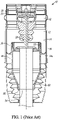
- FIG. 1 shows a portion of a conventional air spring, generally indicated at 10, for a motor vehicle.
- the air spring 10 has a working chamber 12 filled with compressed air that is at least partially delimited by rolling bellow 14, which forms a rolled fold 14a.
- rolling bellow 14 rolls both on a rotationally symmetrical contour of a roll-off piston 16 and on the inner surface of a guide tube 18.
- the rolling bellow 14 is fastened to the connecting parts by clamping rings 24, 26.
- the air spring 10 has a centrally arranged hydraulic damper including a piston rod 28 connected via and by the air spring cover (not shown) to the bodywork.
- the piston rod 28 is connected to a damper 30 that is connected, via a connecting flange (not shown) to a wheel support of the chassis in the conventional manner.
- the piston 16 is a one-piece standing piston that stands on a support ring 32, which is supported by a damper snap ring 34. These lower cost parts are typically made of plastic material and the piston does not provide a large volume for the air spring. The piston 16 is also difficult to package.
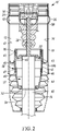
- an exemplary air spring is shown, generally indicated at 10', for a motor vehicle.
- the air spring 10' can be of the type shown in Fig. 1 , the content of which is hereby incorporated by reference into this specification.
- the air spring 10' has at least one working chamber 12 filled with compressed air, which is at least partially delimited by an elastomer rolling bellow 14 that forms a rolled fold 14a.
- the rolling bellow 14 rolls both on a rotationally symmetrical outer surface 15 of a roll-off piston assembly, generally indicated at 16', and on an inner surface 17 of a metal guide tube 18.
- the guide tube 18 surrounds a portion of the rolling bellow 14.
- the rolling bellow 14 is fastened to the connecting parts by clamping rings 24, 26.
- the air spring 10' has a centrally arranged hydraulic damper structure, generally indicated at 27, including a piston rod 28 preferably connected via an air spring cover (not shown) to the bodywork.
- the piston rod 28 is connected to a damper 30 that is connected, via a connecting flange (not shown) to a wheel support of the chassis in the conventional manner.
- the conventional cardanic fold 36 of the bellow 14 is adjacent to an end 38 of the guide tube 18.
- the piston assembly 16' comprises an upper or first piston member 40 that includes a striker cap 42 that has a press-fit connection 43 with an end 45 of the damper 30.
- the first piston member 40 is preferably plastic and thus over-molds the metal striker cap 42.
- the upper piston 40 can be composed of metal such as aluminum or steel or a combination thereof.
- the piston assembly 16' also includes a plastic lower or second member 44 that is supported by (e.g., stands on) a support ring 32 that is supported by the damper snap ring 34.
- the upper piston 40 can be composed of plastic overmolding the striker cap 42, with the lower piston being composed of metal such as aluminum or steel or a combination thereof.
- the damper snap ring 34 is coupled to the periphery of the damper 30.
- the piston assembly 16' is of the standing type.
- the upper piston member 40 is generally cylindrical having an interior 47 that receives a portion of the generally cylindrical periphery 49 of the lower piston member 44.
- An O-ring 46 provides a seal between the upper piston member 40 and the lower piston member 44. Instead of providing O-ring 46, the upper and lower piston members can be welded together.
- Another O-ring 48 provides a seal between damper 30 and the lower piston member 44.
- the piston assembly 16' uses two retaining features, a press-fit connection 43 over the damper 30 at the upper piston member 40, and the lower piston member 44 stands on the support 32 so that both the upper piston member 40 and the lower piston member 44 are held by the damper 30.
- the piston assembly 16' advantageously allows for larger package for volume as compared to the conventional single piston of FIG. 1 , with such volume package being comparable to the conventional aluminum hanging piston, without the additional cost of the aluminum hanging piston and the manufacturing costs associated therewith.
- the piston assembly 16' can replace existing hanging pistons in current production applications by simply adding a support ring.
Claims (4)
- Luftfeder (10'), Folgendes umfassend:einen Balg (14), der zumindest teilweise mindestens eine Arbeitskammer (12) begrenzt, die dazu ausgeführt und angeordnet ist, mit Druckluft gefüllt zu werden, undein Leitrohr (18), das mindestens einen Teil des Balgs (14) umgibt,einen Dämpfer (30),einen Stützring (32), der einem Abschnitt des Dämpfers (30) zugeordnet ist; gekennzeichnet durcheine Kolbenanordnung (16'), die Folgendes umfasst:ein erstes Kolbenelement (40), das eine Metallkappe (42) einschließt, die an einem Ende des Dämpfers (30) eingepresst ist, undein zweites Kolbenelement (44), das an dem ersten Kolbenelement (40) befestigt ist, wobei das zweite Kolbenelement (44) von dem Stützring (32) gelagert wird,wobei das erste Kolbenelement (40) und das zweite Kolbenelement (44) jeweils aus Kunststoff bestehen,wobei die Kappe (42) von dem ersten Kolbenelement (40) aufgeformt ist,wobei der Balg (14) dazu ausgeführt und angeordnet ist, in Bezug zu einer Außenfläche (15) des ersten Kolbenelements (40) und einer Innenfläche (17) des Leitrohrs (18) abzurollen.
- Luftfeder (10') nach Anspruch 1, wobei das erste Kolbenelement (40) im Allgemeinen zylindrisch ist und einen Innenraum (47) aufweist, der einen Teil eines im Allgemeinen zylindrischen Umfangs (49) des zweiten Kolbenelements (44) aufnimmt.
- Luftfeder (10') nach Anspruch 2, ferner einen O-Ring (46) umfassend, der eine Dichtung zwischen dem ersten Kolbenelement (40) und dem zweiten Kolbenelement (44) bereitstellt.
- Luftfeder (10') nach einem der Ansprüche 1 bis 3, ferner einen Dämpfersicherungsring (34) umfassend, der an den Umfang des Dämpfers (30) gekoppelt ist, wobei der Dämpfersicherungsring (34) den Stützring (32) lagert.
Applications Claiming Priority (1)
| Application Number | Priority Date | Filing Date | Title |
|---|---|---|---|
| US14/516,801 US10125840B2 (en) | 2014-10-17 | 2014-10-17 | Air spring hybrid piston assembly |
Publications (3)
| Publication Number | Publication Date |
|---|---|
| EP3009706A1 EP3009706A1 (de) | 2016-04-20 |
| EP3009706B1 EP3009706B1 (de) | 2019-06-05 |
| EP3009706B2 true EP3009706B2 (de) | 2022-08-10 |
Family
ID=54260633
Family Applications (1)
| Application Number | Title | Priority Date | Filing Date |
|---|---|---|---|
| EP15187821.2A Active EP3009706B2 (de) | 2014-10-17 | 2015-10-01 | Hybride luftfederkolbenanordnung |
Country Status (3)
| Country | Link |
|---|---|
| US (1) | US10125840B2 (de) |
| EP (1) | EP3009706B2 (de) |
| JP (1) | JP6165212B2 (de) |
Families Citing this family (10)
| Publication number | Priority date | Publication date | Assignee | Title |
|---|---|---|---|---|
| WO2014135174A1 (de) * | 2013-03-04 | 2014-09-12 | Vibracoustic Cv Air Springs Gmbh | Luftfederanordnung oder luftfederdämpfer mit integrierter ventilsteuerung |
| US10543729B2 (en) * | 2015-10-31 | 2020-01-28 | Firestone Industrial Products Company, Llc | End mount assemblies as well as gas spring and damper assemblies including same |
| US10618366B2 (en) * | 2016-07-08 | 2020-04-14 | Continental Automotive Systems, Inc. | Vehicle air strut with twist lock closure cover |
| WO2019068790A1 (de) * | 2017-10-04 | 2019-04-11 | Continental Teves Ag & Co. Ohg | Luftfederbein mit einem kunststoff-luftfederdeckel |
| CN111433486B (zh) * | 2017-12-01 | 2022-05-10 | 大陆-特韦斯贸易合伙股份公司及两合公司 | 盖中具有加强芯的空气弹簧滑柱组件 |
| DE102018207372B4 (de) * | 2018-05-11 | 2020-07-09 | Thyssenkrupp Ag | Adapterstück zur kraftschlüssigen Verbindung eines Dämpferrohrs und eines Luftfederkolbens, Luftfederdämpfersystem und Verfahren zur Herstellung eines Luftfederdämpfersystems |
| DE102019131319A1 (de) * | 2019-11-20 | 2021-05-20 | Thyssenkrupp Ag | Schwingungsdämpfer und Kraftfahrzeug mit einem solchen Schwingungsdämpfer |
| CN112682458A (zh) * | 2021-01-25 | 2021-04-20 | 蔚来汽车科技(安徽)有限公司 | 减震器以及汽车 |
| DE102021103856A1 (de) * | 2021-02-18 | 2022-08-18 | Vibracoustic Se | Luftfeder und Fahrzeug umfassend die Luftfeder |
| US20230191865A1 (en) * | 2021-12-20 | 2023-06-22 | Continental Automotive Systems, Inc. | Airspring gaiter with sliding joint |
Citations (17)
| Publication number | Priority date | Publication date | Assignee | Title |
|---|---|---|---|---|
| US2180795A (en) † | 1937-10-02 | 1939-11-21 | Niels A Christensen | Packing |
| US4555096A (en) † | 1980-11-20 | 1985-11-26 | Ford Motor Company | Pneumatic spring and strut assembly |
| US4802657A (en) † | 1986-06-23 | 1989-02-07 | Monroe Auto Equipment Company | Vehicle leveling shock absorber assembly |
| EP0318696A2 (de) † | 1987-12-04 | 1989-06-07 | Bridgestone/Firestone, Inc. | Luftfederaufhängung mit zweiseitiger Isolierung |
| US5636831A (en) † | 1994-04-29 | 1997-06-10 | Fichtel & Sachs Ag | Shock absorber and pneumatic spring assembly |
| DE19753637A1 (de) † | 1996-12-17 | 1998-06-18 | Phoenix Ag | Luftfedersystem |
| US6386524B1 (en) † | 2000-02-15 | 2002-05-14 | Bfs Diversified Products, Llc | Pedestal mounted full reservoir air spring piston |
| EP1327539A2 (de) † | 2002-01-10 | 2003-07-16 | ThyssenKrupp Bilstein GmbH | Luftfederbein für Kraftfahrzeuge |
| JP2005180615A (ja) † | 2003-12-19 | 2005-07-07 | Aisin Seiki Co Ltd | 空気ばね装置及び懸架装置 |
| WO2007104671A1 (en) † | 2006-03-10 | 2007-09-20 | Trelleborg Automotive Uk Ltd. | Air spring with improved piston |
| EP1693233B1 (de) † | 2005-02-21 | 2009-04-22 | Continental Aktiengesellschaft | Luftfederbein mit zentrisch angeordnetem Dämpfer |
| JP4329681B2 (ja) † | 2004-11-30 | 2009-09-09 | トヨタ自動車株式会社 | サスペンション装置 |
| US20100127438A1 (en) † | 2007-07-27 | 2010-05-27 | Martin Eise | Plunger piston |
| US20100237549A1 (en) † | 2006-08-03 | 2010-09-23 | Joachim Jeischik | Air Spring for Vehicle |
| DE102012003302A1 (de) † | 2012-02-18 | 2013-08-22 | Audi Ag | Vorrichtung zum Verstellen der Federrate einer Gasfeder |
| WO2014029543A1 (de) † | 2012-08-21 | 2014-02-27 | Continental Teves Ag & Co. Ohg | Luftfedermodul |
| WO2016022539A1 (en) † | 2014-08-04 | 2016-02-11 | Firestone Industrial Products Company, Llc | Support and carrier assemblies as well as end member assemblies and gas spring and damper assemblies including same |
Family Cites Families (15)
| Publication number | Priority date | Publication date | Assignee | Title |
|---|---|---|---|---|
| JPS609712A (ja) | 1983-06-29 | 1985-01-18 | Plus Eng Co Ltd | 靭性ならびに耐摩耗性の良好な押出ピン |
| JPS609712U (ja) * | 1983-06-30 | 1985-01-23 | トヨタ自動車株式会社 | エアサスペンシヨン |
| US5135203A (en) * | 1986-06-23 | 1992-08-04 | Monroe Auto Equipment Company | Vehicle leveling shock absorber assembly |
| US4712776A (en) * | 1986-07-14 | 1987-12-15 | The Firestone Tire & Rubber Company | Air spring suspension system |
| JPH0396444A (ja) | 1989-09-11 | 1991-04-22 | Toshiba Corp | き電システム |
| JP2531985Y2 (ja) * | 1990-01-20 | 1997-04-09 | トキコ株式会社 | サスペンション装置 |
| JPH03244844A (ja) | 1990-02-20 | 1991-10-31 | Tokico Ltd | エアサスペンション |
| JP3673012B2 (ja) | 1996-03-13 | 2005-07-20 | 株式会社日立製作所 | エアサスペンション装置 |
| JP3613652B2 (ja) | 1996-09-17 | 2005-01-26 | トヨタ自動車株式会社 | 車両用サスペンション装置の減衰力制御装置 |
| DE102004053256A1 (de) | 2004-11-04 | 2006-05-11 | Contitech Luftfedersysteme Gmbh | Luftfeder-Dämpfer-Modul |
| DE102004060466A1 (de) * | 2004-12-16 | 2006-07-06 | Contitech Luftfedersysteme Gmbh | Luftfeder-Dämpfer-Modul |
| JP2006234070A (ja) | 2005-02-25 | 2006-09-07 | Kayaba Ind Co Ltd | 単筒型油圧緩衝器 |
| US20060207847A1 (en) * | 2005-02-25 | 2006-09-21 | Shigeru Kojima | Single-cylinder hydraulic shock absorber |
| US8517357B2 (en) | 2009-06-19 | 2013-08-27 | Firestone Industrial Products Company, Llc | Gas spring and damper assembly |
| DE102012103358A1 (de) * | 2012-04-18 | 2013-10-24 | Contitech Luftfedersysteme Gmbh | Abrollkolben für einen Luftfederrollbalg |
-
2014
- 2014-10-17 US US14/516,801 patent/US10125840B2/en active Active
-
2015
- 2015-10-01 EP EP15187821.2A patent/EP3009706B2/de active Active
- 2015-10-16 JP JP2015204448A patent/JP6165212B2/ja active Active
Patent Citations (17)
| Publication number | Priority date | Publication date | Assignee | Title |
|---|---|---|---|---|
| US2180795A (en) † | 1937-10-02 | 1939-11-21 | Niels A Christensen | Packing |
| US4555096A (en) † | 1980-11-20 | 1985-11-26 | Ford Motor Company | Pneumatic spring and strut assembly |
| US4802657A (en) † | 1986-06-23 | 1989-02-07 | Monroe Auto Equipment Company | Vehicle leveling shock absorber assembly |
| EP0318696A2 (de) † | 1987-12-04 | 1989-06-07 | Bridgestone/Firestone, Inc. | Luftfederaufhängung mit zweiseitiger Isolierung |
| US5636831A (en) † | 1994-04-29 | 1997-06-10 | Fichtel & Sachs Ag | Shock absorber and pneumatic spring assembly |
| DE19753637A1 (de) † | 1996-12-17 | 1998-06-18 | Phoenix Ag | Luftfedersystem |
| US6386524B1 (en) † | 2000-02-15 | 2002-05-14 | Bfs Diversified Products, Llc | Pedestal mounted full reservoir air spring piston |
| EP1327539A2 (de) † | 2002-01-10 | 2003-07-16 | ThyssenKrupp Bilstein GmbH | Luftfederbein für Kraftfahrzeuge |
| JP2005180615A (ja) † | 2003-12-19 | 2005-07-07 | Aisin Seiki Co Ltd | 空気ばね装置及び懸架装置 |
| JP4329681B2 (ja) † | 2004-11-30 | 2009-09-09 | トヨタ自動車株式会社 | サスペンション装置 |
| EP1693233B1 (de) † | 2005-02-21 | 2009-04-22 | Continental Aktiengesellschaft | Luftfederbein mit zentrisch angeordnetem Dämpfer |
| WO2007104671A1 (en) † | 2006-03-10 | 2007-09-20 | Trelleborg Automotive Uk Ltd. | Air spring with improved piston |
| US20100237549A1 (en) † | 2006-08-03 | 2010-09-23 | Joachim Jeischik | Air Spring for Vehicle |
| US20100127438A1 (en) † | 2007-07-27 | 2010-05-27 | Martin Eise | Plunger piston |
| DE102012003302A1 (de) † | 2012-02-18 | 2013-08-22 | Audi Ag | Vorrichtung zum Verstellen der Federrate einer Gasfeder |
| WO2014029543A1 (de) † | 2012-08-21 | 2014-02-27 | Continental Teves Ag & Co. Ohg | Luftfedermodul |
| WO2016022539A1 (en) † | 2014-08-04 | 2016-02-11 | Firestone Industrial Products Company, Llc | Support and carrier assemblies as well as end member assemblies and gas spring and damper assemblies including same |
Also Published As
| Publication number | Publication date |
|---|---|
| EP3009706A1 (de) | 2016-04-20 |
| JP2016080176A (ja) | 2016-05-16 |
| US10125840B2 (en) | 2018-11-13 |
| JP6165212B2 (ja) | 2017-07-19 |
| US20160108985A1 (en) | 2016-04-21 |
| EP3009706B1 (de) | 2019-06-05 |
Similar Documents
| Publication | Publication Date | Title |
|---|---|---|
| EP3009706B1 (de) | Hybride luftfederkolbenanordnung | |
| CN106662187B (zh) | 支架和滑架组件以及端构件组件,以及包括这些组件的气弹簧和阻尼器组件 | |
| US9193239B2 (en) | Pneumatic spring device for a motor vehicle | |
| US8979076B2 (en) | Air spring device | |
| CN103502679B (zh) | 阻尼管加强套筒 | |
| US9834059B2 (en) | Suspension strut for a motor vehicle with a height-adjustment device | |
| US10851864B2 (en) | Air spring unit having a divided outer guide | |
| US10315478B2 (en) | Bonded guide tube and bellow assembly for air spring | |
| JP6438816B2 (ja) | エアサスペンション | |
| US20160107496A1 (en) | Air spring | |
| US20160096585A1 (en) | Diaphragm unit and suspension | |
| EP2892740B1 (de) | Luftfeder mit einer linearisierten federrate | |
| JP5307486B2 (ja) | 空気ばね | |
| US20060191757A1 (en) | Single cylinder hydraulic shock absorber | |
| CN104271981A (zh) | 空气弹簧和用于翻折空气弹簧的空气弹簧气囊的方法 | |
| CN105387074A (zh) | 支架轴承单元,配备支架轴承单元的机动车辆和制造方法 | |
| US9370985B2 (en) | Piston with crush fins | |
| US20180236837A1 (en) | Suspension Strut Bearing | |
| US10302169B2 (en) | Hydraulic vibration damper | |
| US20140210170A1 (en) | Air spring for vehicles | |
| US9517672B2 (en) | Shock absorber | |
| WO2015119156A1 (ja) | 緩衝器 | |
| US10451135B2 (en) | Air spring sleeves swage assembly | |
| JP6511337B2 (ja) | 空気ばね | |
| US20160129748A1 (en) | Air Spring Using Laminated Material To Reduce NVH Issues |
Legal Events
| Date | Code | Title | Description |
|---|---|---|---|
| PUAI | Public reference made under article 153(3) epc to a published international application that has entered the european phase |
Free format text: ORIGINAL CODE: 0009012 |
|
| AK | Designated contracting states |
Kind code of ref document: A1 Designated state(s): AL AT BE BG CH CY CZ DE DK EE ES FI FR GB GR HR HU IE IS IT LI LT LU LV MC MK MT NL NO PL PT RO RS SE SI SK SM TR |
|
| AX | Request for extension of the european patent |
Extension state: BA ME |
|
| 17P | Request for examination filed |
Effective date: 20161020 |
|
| RBV | Designated contracting states (corrected) |
Designated state(s): AL AT BE BG CH CY CZ DE DK EE ES FI FR GB GR HR HU IE IS IT LI LT LU LV MC MK MT NL NO PL PT RO RS SE SI SK SM TR |
|
| RIC1 | Information provided on ipc code assigned before grant |
Ipc: F16F 9/05 20060101ALI20181129BHEP Ipc: F16F 9/084 20060101AFI20181129BHEP Ipc: B60G 15/14 20060101ALI20181129BHEP Ipc: B60G 11/27 20060101ALI20181129BHEP |
|
| GRAP | Despatch of communication of intention to grant a patent |
Free format text: ORIGINAL CODE: EPIDOSNIGR1 |
|
| STAA | Information on the status of an ep patent application or granted ep patent |
Free format text: STATUS: GRANT OF PATENT IS INTENDED |
|
| INTG | Intention to grant announced |
Effective date: 20190108 |
|
| GRAS | Grant fee paid |
Free format text: ORIGINAL CODE: EPIDOSNIGR3 |
|
| GRAA | (expected) grant |
Free format text: ORIGINAL CODE: 0009210 |
|
| STAA | Information on the status of an ep patent application or granted ep patent |
Free format text: STATUS: THE PATENT HAS BEEN GRANTED |
|
| AK | Designated contracting states |
Kind code of ref document: B1 Designated state(s): AL AT BE BG CH CY CZ DE DK EE ES FI FR GB GR HR HU IE IS IT LI LT LU LV MC MK MT NL NO PL PT RO RS SE SI SK SM TR |
|
| REG | Reference to a national code |
Ref country code: GB Ref legal event code: FG4D |
|
| REG | Reference to a national code |
Ref country code: CH Ref legal event code: EP |
|
| REG | Reference to a national code |
Ref country code: AT Ref legal event code: REF Ref document number: 1140301 Country of ref document: AT Kind code of ref document: T Effective date: 20190615 |
|
| REG | Reference to a national code |
Ref country code: IE Ref legal event code: FG4D |
|
| REG | Reference to a national code |
Ref country code: DE Ref legal event code: R096 Ref document number: 602015031295 Country of ref document: DE |
|
| REG | Reference to a national code |
Ref country code: NL Ref legal event code: MP Effective date: 20190605 |
|
| REG | Reference to a national code |
Ref country code: LT Ref legal event code: MG4D |
|
| PG25 | Lapsed in a contracting state [announced via postgrant information from national office to epo] |
Ref country code: FI Free format text: LAPSE BECAUSE OF FAILURE TO SUBMIT A TRANSLATION OF THE DESCRIPTION OR TO PAY THE FEE WITHIN THE PRESCRIBED TIME-LIMIT Effective date: 20190605 Ref country code: NO Free format text: LAPSE BECAUSE OF FAILURE TO SUBMIT A TRANSLATION OF THE DESCRIPTION OR TO PAY THE FEE WITHIN THE PRESCRIBED TIME-LIMIT Effective date: 20190905 Ref country code: HR Free format text: LAPSE BECAUSE OF FAILURE TO SUBMIT A TRANSLATION OF THE DESCRIPTION OR TO PAY THE FEE WITHIN THE PRESCRIBED TIME-LIMIT Effective date: 20190605 Ref country code: LT Free format text: LAPSE BECAUSE OF FAILURE TO SUBMIT A TRANSLATION OF THE DESCRIPTION OR TO PAY THE FEE WITHIN THE PRESCRIBED TIME-LIMIT Effective date: 20190605 Ref country code: ES Free format text: LAPSE BECAUSE OF FAILURE TO SUBMIT A TRANSLATION OF THE DESCRIPTION OR TO PAY THE FEE WITHIN THE PRESCRIBED TIME-LIMIT Effective date: 20190605 Ref country code: SE Free format text: LAPSE BECAUSE OF FAILURE TO SUBMIT A TRANSLATION OF THE DESCRIPTION OR TO PAY THE FEE WITHIN THE PRESCRIBED TIME-LIMIT Effective date: 20190605 Ref country code: AL Free format text: LAPSE BECAUSE OF FAILURE TO SUBMIT A TRANSLATION OF THE DESCRIPTION OR TO PAY THE FEE WITHIN THE PRESCRIBED TIME-LIMIT Effective date: 20190605 |
|
| PG25 | Lapsed in a contracting state [announced via postgrant information from national office to epo] |
Ref country code: BG Free format text: LAPSE BECAUSE OF FAILURE TO SUBMIT A TRANSLATION OF THE DESCRIPTION OR TO PAY THE FEE WITHIN THE PRESCRIBED TIME-LIMIT Effective date: 20190905 Ref country code: LV Free format text: LAPSE BECAUSE OF FAILURE TO SUBMIT A TRANSLATION OF THE DESCRIPTION OR TO PAY THE FEE WITHIN THE PRESCRIBED TIME-LIMIT Effective date: 20190605 Ref country code: RS Free format text: LAPSE BECAUSE OF FAILURE TO SUBMIT A TRANSLATION OF THE DESCRIPTION OR TO PAY THE FEE WITHIN THE PRESCRIBED TIME-LIMIT Effective date: 20190605 Ref country code: GR Free format text: LAPSE BECAUSE OF FAILURE TO SUBMIT A TRANSLATION OF THE DESCRIPTION OR TO PAY THE FEE WITHIN THE PRESCRIBED TIME-LIMIT Effective date: 20190906 |
|
| REG | Reference to a national code |
Ref country code: AT Ref legal event code: MK05 Ref document number: 1140301 Country of ref document: AT Kind code of ref document: T Effective date: 20190605 |
|
| PG25 | Lapsed in a contracting state [announced via postgrant information from national office to epo] |
Ref country code: RO Free format text: LAPSE BECAUSE OF FAILURE TO SUBMIT A TRANSLATION OF THE DESCRIPTION OR TO PAY THE FEE WITHIN THE PRESCRIBED TIME-LIMIT Effective date: 20190605 Ref country code: PT Free format text: LAPSE BECAUSE OF FAILURE TO SUBMIT A TRANSLATION OF THE DESCRIPTION OR TO PAY THE FEE WITHIN THE PRESCRIBED TIME-LIMIT Effective date: 20191007 Ref country code: SK Free format text: LAPSE BECAUSE OF FAILURE TO SUBMIT A TRANSLATION OF THE DESCRIPTION OR TO PAY THE FEE WITHIN THE PRESCRIBED TIME-LIMIT Effective date: 20190605 Ref country code: AT Free format text: LAPSE BECAUSE OF FAILURE TO SUBMIT A TRANSLATION OF THE DESCRIPTION OR TO PAY THE FEE WITHIN THE PRESCRIBED TIME-LIMIT Effective date: 20190605 Ref country code: NL Free format text: LAPSE BECAUSE OF FAILURE TO SUBMIT A TRANSLATION OF THE DESCRIPTION OR TO PAY THE FEE WITHIN THE PRESCRIBED TIME-LIMIT Effective date: 20190605 Ref country code: EE Free format text: LAPSE BECAUSE OF FAILURE TO SUBMIT A TRANSLATION OF THE DESCRIPTION OR TO PAY THE FEE WITHIN THE PRESCRIBED TIME-LIMIT Effective date: 20190605 Ref country code: CZ Free format text: LAPSE BECAUSE OF FAILURE TO SUBMIT A TRANSLATION OF THE DESCRIPTION OR TO PAY THE FEE WITHIN THE PRESCRIBED TIME-LIMIT Effective date: 20190605 |
|
| PG25 | Lapsed in a contracting state [announced via postgrant information from national office to epo] |
Ref country code: IT Free format text: LAPSE BECAUSE OF FAILURE TO SUBMIT A TRANSLATION OF THE DESCRIPTION OR TO PAY THE FEE WITHIN THE PRESCRIBED TIME-LIMIT Effective date: 20190605 Ref country code: SM Free format text: LAPSE BECAUSE OF FAILURE TO SUBMIT A TRANSLATION OF THE DESCRIPTION OR TO PAY THE FEE WITHIN THE PRESCRIBED TIME-LIMIT Effective date: 20190605 Ref country code: IS Free format text: LAPSE BECAUSE OF FAILURE TO SUBMIT A TRANSLATION OF THE DESCRIPTION OR TO PAY THE FEE WITHIN THE PRESCRIBED TIME-LIMIT Effective date: 20191005 |
|
| REG | Reference to a national code |
Ref country code: DE Ref legal event code: R026 Ref document number: 602015031295 Country of ref document: DE |
|
| PLBI | Opposition filed |
Free format text: ORIGINAL CODE: 0009260 |
|
| PLAX | Notice of opposition and request to file observation + time limit sent |
Free format text: ORIGINAL CODE: EPIDOSNOBS2 |
|
| PG25 | Lapsed in a contracting state [announced via postgrant information from national office to epo] |
Ref country code: TR Free format text: LAPSE BECAUSE OF FAILURE TO SUBMIT A TRANSLATION OF THE DESCRIPTION OR TO PAY THE FEE WITHIN THE PRESCRIBED TIME-LIMIT Effective date: 20190605 |
|
| 26 | Opposition filed |
Opponent name: VIBRACOUSTIC AG Effective date: 20200304 |
|
| PG25 | Lapsed in a contracting state [announced via postgrant information from national office to epo] |
Ref country code: PL Free format text: LAPSE BECAUSE OF FAILURE TO SUBMIT A TRANSLATION OF THE DESCRIPTION OR TO PAY THE FEE WITHIN THE PRESCRIBED TIME-LIMIT Effective date: 20190605 Ref country code: DK Free format text: LAPSE BECAUSE OF FAILURE TO SUBMIT A TRANSLATION OF THE DESCRIPTION OR TO PAY THE FEE WITHIN THE PRESCRIBED TIME-LIMIT Effective date: 20190605 |
|
| PG25 | Lapsed in a contracting state [announced via postgrant information from national office to epo] |
Ref country code: SI Free format text: LAPSE BECAUSE OF FAILURE TO SUBMIT A TRANSLATION OF THE DESCRIPTION OR TO PAY THE FEE WITHIN THE PRESCRIBED TIME-LIMIT Effective date: 20190605 Ref country code: MC Free format text: LAPSE BECAUSE OF FAILURE TO SUBMIT A TRANSLATION OF THE DESCRIPTION OR TO PAY THE FEE WITHIN THE PRESCRIBED TIME-LIMIT Effective date: 20190605 |
|
| REG | Reference to a national code |
Ref country code: CH Ref legal event code: PL |
|
| PLBB | Reply of patent proprietor to notice(s) of opposition received |
Free format text: ORIGINAL CODE: EPIDOSNOBS3 |
|
| PG25 | Lapsed in a contracting state [announced via postgrant information from national office to epo] |
Ref country code: LU Free format text: LAPSE BECAUSE OF NON-PAYMENT OF DUE FEES Effective date: 20191001 Ref country code: LI Free format text: LAPSE BECAUSE OF NON-PAYMENT OF DUE FEES Effective date: 20191031 Ref country code: CH Free format text: LAPSE BECAUSE OF NON-PAYMENT OF DUE FEES Effective date: 20191031 |
|
| REG | Reference to a national code |
Ref country code: BE Ref legal event code: MM Effective date: 20191031 |
|
| PG25 | Lapsed in a contracting state [announced via postgrant information from national office to epo] |
Ref country code: BE Free format text: LAPSE BECAUSE OF NON-PAYMENT OF DUE FEES Effective date: 20191031 |
|
| GBPC | Gb: european patent ceased through non-payment of renewal fee |
Effective date: 20191001 |
|
| PG25 | Lapsed in a contracting state [announced via postgrant information from national office to epo] |
Ref country code: IE Free format text: LAPSE BECAUSE OF NON-PAYMENT OF DUE FEES Effective date: 20191001 Ref country code: GB Free format text: LAPSE BECAUSE OF NON-PAYMENT OF DUE FEES Effective date: 20191001 |
|
| RAP2 | Party data changed (patent owner data changed or rights of a patent transferred) |
Owner name: CONTINENTAL AUTOMOTIVE SYSTEMS, INC. |
|
| PG25 | Lapsed in a contracting state [announced via postgrant information from national office to epo] |
Ref country code: CY Free format text: LAPSE BECAUSE OF FAILURE TO SUBMIT A TRANSLATION OF THE DESCRIPTION OR TO PAY THE FEE WITHIN THE PRESCRIBED TIME-LIMIT Effective date: 20190605 |
|
| PG25 | Lapsed in a contracting state [announced via postgrant information from national office to epo] |
Ref country code: HU Free format text: LAPSE BECAUSE OF FAILURE TO SUBMIT A TRANSLATION OF THE DESCRIPTION OR TO PAY THE FEE WITHIN THE PRESCRIBED TIME-LIMIT; INVALID AB INITIO Effective date: 20151001 Ref country code: MT Free format text: LAPSE BECAUSE OF FAILURE TO SUBMIT A TRANSLATION OF THE DESCRIPTION OR TO PAY THE FEE WITHIN THE PRESCRIBED TIME-LIMIT Effective date: 20190605 |
|
| PG25 | Lapsed in a contracting state [announced via postgrant information from national office to epo] |
Ref country code: MK Free format text: LAPSE BECAUSE OF FAILURE TO SUBMIT A TRANSLATION OF THE DESCRIPTION OR TO PAY THE FEE WITHIN THE PRESCRIBED TIME-LIMIT Effective date: 20190605 |
|
| PUAH | Patent maintained in amended form |
Free format text: ORIGINAL CODE: 0009272 |
|
| STAA | Information on the status of an ep patent application or granted ep patent |
Free format text: STATUS: PATENT MAINTAINED AS AMENDED |
|
| 27A | Patent maintained in amended form |
Effective date: 20220810 |
|
| AK | Designated contracting states |
Kind code of ref document: B2 Designated state(s): AL AT BE BG CH CY CZ DE DK EE ES FI FR GB GR HR HU IE IS IT LI LT LU LV MC MK MT NL NO PL PT RO RS SE SI SK SM TR |
|
| REG | Reference to a national code |
Ref country code: DE Ref legal event code: R102 Ref document number: 602015031295 Country of ref document: DE |
|
| PGFP | Annual fee paid to national office [announced via postgrant information from national office to epo] |
Ref country code: FR Payment date: 20231026 Year of fee payment: 9 Ref country code: DE Payment date: 20231031 Year of fee payment: 9 |