EP3008117B1 - Pore initiation technique - Google Patents
Pore initiation technique Download PDFInfo
- Publication number
- EP3008117B1 EP3008117B1 EP14811094.3A EP14811094A EP3008117B1 EP 3008117 B1 EP3008117 B1 EP 3008117B1 EP 14811094 A EP14811094 A EP 14811094A EP 3008117 B1 EP3008117 B1 EP 3008117B1
- Authority
- EP
- European Patent Office
- Prior art keywords
- polymeric material
- foregoing
- additive
- drawn
- thermoplastic composition
- Prior art date
- Legal status (The legal status is an assumption and is not a legal conclusion. Google has not performed a legal analysis and makes no representation as to the accuracy of the status listed.)
- Active
Links
Images


Classifications
-
- B—PERFORMING OPERATIONS; TRANSPORTING
- B29—WORKING OF PLASTICS; WORKING OF SUBSTANCES IN A PLASTIC STATE IN GENERAL
- B29C—SHAPING OR JOINING OF PLASTICS; SHAPING OF MATERIAL IN A PLASTIC STATE, NOT OTHERWISE PROVIDED FOR; AFTER-TREATMENT OF THE SHAPED PRODUCTS, e.g. REPAIRING
- B29C55/00—Shaping by stretching, e.g. drawing through a die; Apparatus therefor
- B29C55/02—Shaping by stretching, e.g. drawing through a die; Apparatus therefor of plates or sheets
- B29C55/18—Shaping by stretching, e.g. drawing through a die; Apparatus therefor of plates or sheets by squeezing between surfaces, e.g. rollers
-
- B—PERFORMING OPERATIONS; TRANSPORTING
- B29—WORKING OF PLASTICS; WORKING OF SUBSTANCES IN A PLASTIC STATE IN GENERAL
- B29C—SHAPING OR JOINING OF PLASTICS; SHAPING OF MATERIAL IN A PLASTIC STATE, NOT OTHERWISE PROVIDED FOR; AFTER-TREATMENT OF THE SHAPED PRODUCTS, e.g. REPAIRING
- B29C44/00—Shaping by internal pressure generated in the material, e.g. swelling or foaming ; Producing porous or cellular expanded plastics articles
- B29C44/34—Auxiliary operations
- B29C44/3469—Cell or pore nucleation
- B29C44/3473—Cell or pore nucleation by shearing forces
-
- B—PERFORMING OPERATIONS; TRANSPORTING
- B29—WORKING OF PLASTICS; WORKING OF SUBSTANCES IN A PLASTIC STATE IN GENERAL
- B29C—SHAPING OR JOINING OF PLASTICS; SHAPING OF MATERIAL IN A PLASTIC STATE, NOT OTHERWISE PROVIDED FOR; AFTER-TREATMENT OF THE SHAPED PRODUCTS, e.g. REPAIRING
- B29C44/00—Shaping by internal pressure generated in the material, e.g. swelling or foaming ; Producing porous or cellular expanded plastics articles
- B29C44/20—Shaping by internal pressure generated in the material, e.g. swelling or foaming ; Producing porous or cellular expanded plastics articles for articles of indefinite length
- B29C44/28—Expanding the moulding material on continuous moving surfaces without restricting the upwards growth of the foam
-
- B—PERFORMING OPERATIONS; TRANSPORTING
- B29—WORKING OF PLASTICS; WORKING OF SUBSTANCES IN A PLASTIC STATE IN GENERAL
- B29C—SHAPING OR JOINING OF PLASTICS; SHAPING OF MATERIAL IN A PLASTIC STATE, NOT OTHERWISE PROVIDED FOR; AFTER-TREATMENT OF THE SHAPED PRODUCTS, e.g. REPAIRING
- B29C44/00—Shaping by internal pressure generated in the material, e.g. swelling or foaming ; Producing porous or cellular expanded plastics articles
- B29C44/20—Shaping by internal pressure generated in the material, e.g. swelling or foaming ; Producing porous or cellular expanded plastics articles for articles of indefinite length
- B29C44/30—Expanding the moulding material between endless belts or rollers
-
- C—CHEMISTRY; METALLURGY
- C08—ORGANIC MACROMOLECULAR COMPOUNDS; THEIR PREPARATION OR CHEMICAL WORKING-UP; COMPOSITIONS BASED THEREON
- C08J—WORKING-UP; GENERAL PROCESSES OF COMPOUNDING; AFTER-TREATMENT NOT COVERED BY SUBCLASSES C08B, C08C, C08F, C08G or C08H
- C08J5/00—Manufacture of articles or shaped materials containing macromolecular substances
- C08J5/18—Manufacture of films or sheets
-
- C—CHEMISTRY; METALLURGY
- C08—ORGANIC MACROMOLECULAR COMPOUNDS; THEIR PREPARATION OR CHEMICAL WORKING-UP; COMPOSITIONS BASED THEREON
- C08L—COMPOSITIONS OF MACROMOLECULAR COMPOUNDS
- C08L23/00—Compositions of homopolymers or copolymers of unsaturated aliphatic hydrocarbons having only one carbon-to-carbon double bond; Compositions of derivatives of such polymers
- C08L23/02—Compositions of homopolymers or copolymers of unsaturated aliphatic hydrocarbons having only one carbon-to-carbon double bond; Compositions of derivatives of such polymers not modified by chemical after-treatment
- C08L23/10—Homopolymers or copolymers of propene
- C08L23/12—Polypropene
-
- B—PERFORMING OPERATIONS; TRANSPORTING
- B29—WORKING OF PLASTICS; WORKING OF SUBSTANCES IN A PLASTIC STATE IN GENERAL
- B29K—INDEXING SCHEME ASSOCIATED WITH SUBCLASSES B29B, B29C OR B29D, RELATING TO MOULDING MATERIALS OR TO MATERIALS FOR MOULDS, REINFORCEMENTS, FILLERS OR PREFORMED PARTS, e.g. INSERTS
- B29K2105/00—Condition, form or state of moulded material or of the material to be shaped
- B29K2105/04—Condition, form or state of moulded material or of the material to be shaped cellular or porous
- B29K2105/041—Microporous
-
- B—PERFORMING OPERATIONS; TRANSPORTING
- B29—WORKING OF PLASTICS; WORKING OF SUBSTANCES IN A PLASTIC STATE IN GENERAL
- B29K—INDEXING SCHEME ASSOCIATED WITH SUBCLASSES B29B, B29C OR B29D, RELATING TO MOULDING MATERIALS OR TO MATERIALS FOR MOULDS, REINFORCEMENTS, FILLERS OR PREFORMED PARTS, e.g. INSERTS
- B29K2105/00—Condition, form or state of moulded material or of the material to be shaped
- B29K2105/06—Condition, form or state of moulded material or of the material to be shaped containing reinforcements, fillers or inserts
- B29K2105/16—Fillers
- B29K2105/162—Nanoparticles
-
- C—CHEMISTRY; METALLURGY
- C08—ORGANIC MACROMOLECULAR COMPOUNDS; THEIR PREPARATION OR CHEMICAL WORKING-UP; COMPOSITIONS BASED THEREON
- C08J—WORKING-UP; GENERAL PROCESSES OF COMPOUNDING; AFTER-TREATMENT NOT COVERED BY SUBCLASSES C08B, C08C, C08F, C08G or C08H
- C08J2205/00—Foams characterised by their properties
- C08J2205/04—Foams characterised by their properties characterised by the foam pores
- C08J2205/048—Bimodal pore distribution, e.g. micropores and nanopores coexisting in the same foam
-
- C—CHEMISTRY; METALLURGY
- C08—ORGANIC MACROMOLECULAR COMPOUNDS; THEIR PREPARATION OR CHEMICAL WORKING-UP; COMPOSITIONS BASED THEREON
- C08J—WORKING-UP; GENERAL PROCESSES OF COMPOUNDING; AFTER-TREATMENT NOT COVERED BY SUBCLASSES C08B, C08C, C08F, C08G or C08H
- C08J2367/00—Characterised by the use of polyesters obtained by reactions forming a carboxylic ester link in the main chain; Derivatives of such polymers
- C08J2367/04—Polyesters derived from hydroxy carboxylic acids, e.g. lactones
-
- C—CHEMISTRY; METALLURGY
- C08—ORGANIC MACROMOLECULAR COMPOUNDS; THEIR PREPARATION OR CHEMICAL WORKING-UP; COMPOSITIONS BASED THEREON
- C08J—WORKING-UP; GENERAL PROCESSES OF COMPOUNDING; AFTER-TREATMENT NOT COVERED BY SUBCLASSES C08B, C08C, C08F, C08G or C08H
- C08J2423/00—Characterised by the use of homopolymers or copolymers of unsaturated aliphatic hydrocarbons having only one carbon-to-carbon double bond; Derivatives of such polymers
- C08J2423/02—Characterised by the use of homopolymers or copolymers of unsaturated aliphatic hydrocarbons having only one carbon-to-carbon double bond; Derivatives of such polymers not modified by chemical after treatment
- C08J2423/04—Homopolymers or copolymers of ethene
- C08J2423/08—Copolymers of ethene
-
- C—CHEMISTRY; METALLURGY
- C08—ORGANIC MACROMOLECULAR COMPOUNDS; THEIR PREPARATION OR CHEMICAL WORKING-UP; COMPOSITIONS BASED THEREON
- C08J—WORKING-UP; GENERAL PROCESSES OF COMPOUNDING; AFTER-TREATMENT NOT COVERED BY SUBCLASSES C08B, C08C, C08F, C08G or C08H
- C08J2423/00—Characterised by the use of homopolymers or copolymers of unsaturated aliphatic hydrocarbons having only one carbon-to-carbon double bond; Derivatives of such polymers
- C08J2423/02—Characterised by the use of homopolymers or copolymers of unsaturated aliphatic hydrocarbons having only one carbon-to-carbon double bond; Derivatives of such polymers not modified by chemical after treatment
- C08J2423/16—Ethene-propene or ethene-propene-diene copolymers
-
- C—CHEMISTRY; METALLURGY
- C08—ORGANIC MACROMOLECULAR COMPOUNDS; THEIR PREPARATION OR CHEMICAL WORKING-UP; COMPOSITIONS BASED THEREON
- C08J—WORKING-UP; GENERAL PROCESSES OF COMPOUNDING; AFTER-TREATMENT NOT COVERED BY SUBCLASSES C08B, C08C, C08F, C08G or C08H
- C08J9/00—Working-up of macromolecular substances to porous or cellular articles or materials; After-treatment thereof
- C08J9/0061—Working-up of macromolecular substances to porous or cellular articles or materials; After-treatment thereof characterized by the use of several polymeric components
-
- C—CHEMISTRY; METALLURGY
- C08—ORGANIC MACROMOLECULAR COMPOUNDS; THEIR PREPARATION OR CHEMICAL WORKING-UP; COMPOSITIONS BASED THEREON
- C08L—COMPOSITIONS OF MACROMOLECULAR COMPOUNDS
- C08L23/00—Compositions of homopolymers or copolymers of unsaturated aliphatic hydrocarbons having only one carbon-to-carbon double bond; Compositions of derivatives of such polymers
-
- C—CHEMISTRY; METALLURGY
- C08—ORGANIC MACROMOLECULAR COMPOUNDS; THEIR PREPARATION OR CHEMICAL WORKING-UP; COMPOSITIONS BASED THEREON
- C08L—COMPOSITIONS OF MACROMOLECULAR COMPOUNDS
- C08L67/00—Compositions of polyesters obtained by reactions forming a carboxylic ester link in the main chain; Compositions of derivatives of such polymers
- C08L67/04—Polyesters derived from hydroxycarboxylic acids, e.g. lactones
Definitions
- a typical approach to producing such low density materials is by foaming the polymer using physical or chemical blowing agents, which create gas-filled pores though the bulk.
- Chemical blowing agents are compounds that undergo chemical reaction liberating gas that creates the pore structure through the bulk of the polymer.
- Physical blowing agents are typically compressed gases that are dispersed in the polymer and expand creating the pores.
- typical foaming processes induce low molecular orientation because the pore formation happens when the polymer is in the molten state. This reduces the melt strength, thus leading to breaks in high speed production processes with high deformation rates (e.g., fiber spinning, film formation, molding, etc.).
- WO2013/118019 discloses renewable polyester fibers having a low density.
- WO2013/118021 also discloses renewable polyester compositions having a low density.
- WO2010/059448 discloses cavitated polymeric films.
- a method for initiating the formation of pores in a polymeric material that contains a thermoplastic composition includes a continuous phase in which a microinclusion additive and nanoinclusion additive are dispersed in the form of discrete domains, the continuous phase including a matrix polymer.
- the method comprises mechanically drawing the polymeric material through a converging die in a solid state to form a porous network, wherein the porous network includes a plurality of nanopores having an average cross-sectional dimension of about 800 nanometers or less.
- the present invention is directed to a technique for initiating the formation of pores in a polymeric material that contains a thermoplastic composition.
- the thermoplastic composition contains microinclusion and nanoinclusion additives dispersed within a continuous phase that includes a matrix polymer.
- the polymeric material is mechanically drawn (e.g., bending, stretching, twisting, etc.) to impart energy to the interface of the continuous phase and inclusion additives, which enables the inclusion additives to separate from the interface to create the porous network.
- the material is also drawn in a solid state in the sense that it is kept at a temperature (“drawing temperature") below the melting temperature of the matrix polymer.
- the material may be drawn at a temperature of from about -50°C to about 125°C, in some embodiments from about -25°C to about 100°C, and in some embodiments, from about -20°C to about 50°C.
- the drawing temperature may also be below the glass transition temperature of the component having the highest glass transition temperature (e.g., matrix polymer, microinclusion additive, etc.).
- the drawing temperature may be at least about 10°C, in some embodiments at least about 20°C, and in some embodiments, at least about 30°C below the glass transition temperature of the matrix polymer and/or microinclusion additive.
- microinclusion and nanoinclusion additives may also be selected so that they are at least partially incompatible with the matrix polymer so that they become dispersed within the continuous phase as discrete micro-scale and nano-scale phase domains, respectively.
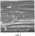
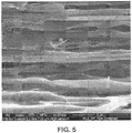
- these micro-scale and nano-scale phase domains are able to interact in a unique manner to create a network of pores, a substantial portion of which are of a nano-scale size.
- elongational strain can initiate intensive localized shear zones and/or stress intensity zones (e.g., normal stresses) near the micro-scale discrete phase domains as a result of stress concentrations that arise from the incompatibility of the materials.
- shear and/or stress intensity zones cause some initial debonding in the polymer matrix adjacent to the micro-scale domains.
- localized shear and/or stress intensity zones may also be created near the nano-scale discrete phase domains that overlap with the micro-scale zones.
- Such overlapping shear and/or stress intensity zones cause even further debonding to occur in the polymer matrix, thereby creating a substantial number of nanopores adjacent to the nano-scaie domains and/or micro-scale domains.
- a bridge can be formed between the boundaries of the pores that act as internal structural "hinges" that help stabilize the network and increase its ability to dissipate energy.
- a unique porous network may be formed in the polymeric material so that the average percent volume occupied by the pores within a given unit volume of the material may be from about 15% to about 80% per cm 3 , in some embodiments from about 20% to about 70%, and in some embodiments, from about 30% to about 60% per cubic centimeter of the material.
- the material may have a relatively low density, such as about 1.2 grams per cubic centimeter (“g/cm 3 ”) or less, in some embodiments about 1.0 g/cm 3 or less, in some embodiments from about 0.2 g/cm 3 to about 0.8 g/cm 3 , and in some embodiments, from about 0.1 g/cm 3 to about 0.5 g/cm 3 .
- a substantial portion of pores in the porous network are also of a "nano-scale" size (“nanopores”), such as those having an average cross-sectional dimension of about 800 nanometers or less, in some embodiments from about 5 to about 700 nanometers, and in some embodiments, from about 10 to about 500 nanometers.
- cross-sectional dimension generally refers to a characteristic dimension (e.g., width or diameter) of a pore, which is substantially orthogonal to its major axis (e.g., length) and also typically substantially orthogonal to the direction of the stress applied during drawing.
- Such nanopores may, for example, constitute about 15 vol.% or more, in some embodiments about 20 vol.% or more, in some embodiments from about 30 vol.% to 100 vol.%, and in some embodiments, from about 40 vol.% to about 90 vol.% of the total pore volume in the polymeric material.
- the nanoporous structure may also provide a variety of functional benefits to the resulting polymeric material.
- a structure can help restrict the flow of fluids through the material and be generally impermeable to fluids (e.g., liquid water), thereby allowing the material to insulate a surface from water penetration.
- the polymeric material may have a relatively high hydrohead value of about 50 centimeters ("cm") or more, in some embodiments about 100 cm or more, in some embodiments, about 150 cm or more, and in some embodiments, from about 200 cm to about 1000 cm, as determined in accordance with ATTCC 127-2008. Other beneficial properties may also be achieved.
- the resulting polymeric material may be generally permeable to water vapors.
- the permeability of the material to water vapor may characterized by its relatively high water vapor transmission rate ("WVTR”), which is the rate at which water vapor permeates through a material as measured in units of grams per meter squared per 24 hours (g/m 2 /24 hrs).
- WVTR water vapor transmission rate
- the polymeric material may exhibit a WVTR of about 300 g/m 2 -24 hours or more, in some embodiments about 500 g/m 2 -24 hours or more, in some embodiments about 1,000 g/m 2 -24 hours or more, and in some embodiments, from about 3,000 to about 15,000 g/m 2 -24 hours, such as determined in accordance with ASTM E96/96M-12, Procedure B or INDA Test Procedure IST-70.4 (01).
- the polymeric material can also act as a thermal barrier that exhibits a relatively low thermal conductivity, such as about 0.40 watts per meter-kelvin ("W/m-K") or less, in some embodiments about 0.20 W/m-K or less, in some embodiments about 0.15 W/m-K or less, in some embodiments from about 0.01 to about 0.12 W/m-K, and in some embodiments, from about 0.02 to about 0.10 W/m-K.
- W/m-K watts per meter-kelvin
- the material is capable of achieving such low thermal conductivity values at relatively low thicknesses, which can allow the material to possess a greater degree of flexibility and conformability, as well as reduce the space it occupies in an article.
- the polymeric material may also exhibit a relatively low "thermal admittance", which is equal to the thermal conductivity of the material divided by its thickness and is provided in units of watts per square meter-kelvins ("W/m 2 K").
- the material may exhibit a thermal admittance of about 1000 W/m 2 K or less, in some embodiments from about 10 to about 800 W/m 2 K, in some embodiments from about 20 to about 500 W/m 2 K, and in some embodiments, from about 40 to about 200 W/m 2 K
- the actual thickness of the polymeric material may depend on its particular form, but typically ranges from about 5 micrometers to about 100 millimeters, in some embodiments from about 10 micrometers to about 50 millimeters, in some embodiments from about 200 micrometers to about 25 millimeters.
- the thermoplastic composition contains a continuous phase within which the microinclusion and nanoinclusion additives are dispersed.
- the continuous phase contains one or more matrix polymers, which typically constitute from about 60 wt.% to about 99 wt.%, in some embodiments from about 75 wt.% to about 98 wt.%, and in some embodiments, from about 80 wt.% to about 95 wt.% of the thermoplastic composition.
- the nature of the matrix polymer(s) used to form the continuous phase is not critical and any suitable polymer may generally be employed, such as polyesters, polyolefins, styrenic polymers, polyamides, etc. In certain embodiments, for example, polyesters may be employed in the composition to form the polymer matrix.
- polyesters such as aliphatic polyesters, such as polycaprolactone, polyesteramides, polylactic acid (PLA) and its copolymers, polyglycolic acid, polyalkylene carbonates (e.g., polyethylene carbonate), poly-3-hydroxybutyrate (PHB), poly-3-hydroxyvalerate (PHV), poly-3-hydroxybutyrate-co-4-hydroybutyrate, poly-3-hydroxybutyrate-co-3-hydroxyvalerate copolymers (PHBV), poly-3-hydroxybutyrate-co-3-hydroxyhexanoate, poly-3-hydroxybutyrate-co-3-hydroxyoctanoate, poly-3-hydroxybutyrate-co-3-hydroxydecanoate, poly-3-hydroxybutyrate-co-3-hydroxyoctadecanoate, and succinate-based aliphatic polymers (e.g., polybutylene succinate, polybutylene succinate adipate, polyethylene succinate, etc.); aliphatic polymers (e.g.,
- the thermoplastic composition may contain at least one polyester that is rigid in nature and thus has a relatively high glass transition temperature.
- the glass transition temperature (“T g ”) may be about 0°C or more, in some embodiments from about 5°C to about 100°C, in some embodiments from about 30°C to about 80°C, and in some embodiments, from about 50°C to about 75°C.
- the polyester may also have a melting temperature of from about 140°C to about 300°C, in some embodiments from about 150°C to about 250°C, and in some embodiments, from about 160°C to about 220°C.
- the melting temperature may be determined using differential scanning calorimetry ("DSC") in accordance with ASTM D-3417.
- the glass transition temperature may be determined by dynamic mechanical analysis in accordance with ASTM E1640-09.
- polylactic acid which may generally be derived from monomer units of any isomer of lactic acid, such as levorotory-lactic acid (“L-lactic acid”), dextrorotatory-lactic acid (“D-lactic acid”), meso-lactic acid, or mixtures thereof.
- Monomer units may also be formed from anhydrides of any isomer of lactic acid, including L-lactide, D-lactide, meso-lactide, or mixtures thereof. Cyclic dimers of such lactic acids and/or lactides may also be employed.
- Any known polymerization method such as polycondensation or ring-opening polymerization, may be used to polymerize lactic acid.
- a small amount of a chain-extending agent may also be employed.
- the polylactic acid may be a homopolymer or a copolymer, such as one that contains monomer units derived from L-lactic acid and monomer units derived from D-lactic acid.
- the rate of content of one of the monomer unit derived from L-lactic acid and the monomer unit derived from D-lactic acid is preferably about 85 mole% or more, in some embodiments about 90 mole% or more, and in some embodiments, about 95 mole% or more.
- polylactic acids each having a different ratio between the monomer unit derived from L-lactic acid and the monomer unit derived from D-lactic acid, may be blended at an arbitrary percentage.
- polylactic acid may also be blended with other types of polymers (e.g., polyolefins, polyesters, etc.).
- the polylactic acid has the following general structure:
- a suitable polylactic acid polymer that may be used in the present invention is commercially available from Biomer, Inc. of Krailling, Germany) under the name BIOMERTM L9000.
- Other suitable polylactic acid polymers are commercially available from Natureworks LLC of Minnetonka, Minnesota (NATUREWORKS®) or Mitsui Chemical (LACEATM).
- Still other suitable polylactic acids may be described in U.S. Patent Nos. 4, 797, 468 ; 5, 470, 944 ; 5, 770, 682 ; 5, 821, 327 ; 5, 880, 254 ; and 6, 326, 458 .
- the polylactic acid typically has a number average molecular weight (“M n ”) ranging from about 40,000 to about 180,000 grams per mole, in some embodiments from about 50,000 to about 160,000 grams per mole, and in some embodiments, from about 80,000 to about 120,000 grams per mole.
- M n number average molecular weight
- M w weight average molecular weight
- the ratio of the weight average molecular weight to the number average molecular weight (“M w /M n "), i.e., the "polydispersity index" is also relatively low.
- the polydispersity index typically ranges from about 1.0 to about 3.0, in some embodiments from about 1.1 to about 2.0, and in some embodiments, from about 1.2 to about 1.8.
- the weight and number average molecular weights may be determined by methods known to those skilled in the art.
- the polylactic acid may also have an apparent viscosity of from about 50 to about 600 Pascal seconds (Pa ⁇ s), in some embodiments from about 100 to about 500 Pa ⁇ s, and in some embodiments, from about 200 to about 400 Pa ⁇ s, as determined at a temperature of 190°C and a shear rate of 1000 sec -1 .
- the melt flow rate of the polylactic acid (on a dry basis) may also range from about 0.1 to about 40 grams per 10 minutes, in some embodiments from about 0.5 to about 20 grams per 10 minutes, and in some embodiments, from about 5 to about 15 grams per 10 minutes, determined at a load of 2160 grams and at 190°C.
- Some types of neat polyesters can absorb water from the ambient environment such that it has a moisture content of about 500 to 600 parts per million (“ppm"), or even greater, based on the dry weight of the starting polylactic acid.
- Moisture content may be determined in a variety of ways as is known in the art, such as in accordance with ASTM D 7191-05, such as described below. Because the presence of water during melt processing can hydrolytically degrade the polyester and reduce its molecular weight, it is sometimes desired to dry the polyester prior to blending.
- the polyester have a moisture content of about 300 parts per million (“ppm") or less, in some embodiments about 200 ppm or less, in some embodiments from about 1 to about 100 ppm prior to blending with the microinclusion and nanoinclusion additives. Drying of the polyester may occur, for instance, at a temperature of from about 50°C to about 100°C, and in some embodiments, from about 70°C to about 80°C.
- ppm parts per million
- the term "microinclusion additive” generally refers to any material that is capable of being dispersed within the polymer matrix in the form of discrete domains of a micro-scale size.
- the domains may have an average cross-sectional dimension of from about 0.05 ⁇ m to about 30 ⁇ m, in some embodiments from about 0.1 ⁇ m to about 25 ⁇ m, in some embodiments from about 0.5 ⁇ m to about 20 ⁇ m, and in some embodiments from about 1 ⁇ m to about 10 ⁇ m.
- cross-sectional dimension generally refers to a characteristic dimension (e.g., width or diameter) of a domain, which is substantially orthogonal to its major axis (e.g., length) and also typically substantially orthogonal to the direction of the stress applied during drawing. While typically formed from the microinclusion additive, it should be also understood that the micro-scale domains may also be formed from a combination of the microinclusion and nanoinclusion additives and/or other components of the composition.
- the microinclusion additive is not critical, and may include liquids, semi-solids, or solids (e.g., amorphous, crystalline, or semi-crystalline).
- the microinclusion additive is polymeric in nature and possesses a relatively high molecular weight to help improve the melt strength and stability of the thermoplastic composition.
- the microinclusion additive polymer may be generally incompatible with the matrix polymer. In this manner, the additive can better become dispersed as discrete phase domains within a continuous phase of the matrix polymer. The discrete domains are capable of absorbing energy that arises from an external force, which increases the overall toughness and strength of the resulting material.
- the domains may have a variety of different shapes, such as elliptical, spherical, cylindrical, plate-like, tubular, etc. In one embodiment, for example, the domains have a substantially elliptical shape.
- the physical dimension of an individual domain is typically small enough to minimize the propagation of cracks through the polymeric material upon the application of an external stress, but large enough to initiate microscopic plastic deformation and allow for shear and/or stress intensity zones at and around particle inclusions.
- the microinclusion additive may nevertheless be selected to have a solubility parameter that is relatively similar to that of the matrix polymer. This can improve the interfacial compatibility and physical interaction of the boundaries of the discrete and continuous phases, and thus reduces the likelihood that the composition will fracture.
- the ratio of the solubility parameter for the matrix polymer to that of the additive is typically from about 0.5 to about 1.5, and in some embodiments, from about 0.8 to about 1.2.
- the microinclusion additive may have a solubility parameter of from about 15 to about 30 MJoules 1/2 /m 3/2 , and in some embodiments, from about 18 to about 22 MJoules 1/2 /m 3/2 , while polylactic acid may have a solubility parameter of about 20.5 MJoules 1/2 /m 3/2 .
- the microinclusion additive may also have a certain melt flow rate (or viscosity) to ensure that the discrete domains and resulting pores can be adequately maintained. For example, if the melt flow rate of the additive is too high, it tends to flow and disperse uncontrollably through the continuous phase. This results in lamellar, plate-like domains or co-continuous phase structures that are difficult to maintain and also likely to prematurely fracture. Conversely, if the melt flow rate of the additive is too low, it tends to clump together and form very large elliptical domains, which are difficult to disperse during blending. This may cause uneven distribution of the additive through the entirety of the continuous phase.
- the ratio of the melt flow rate of the microinclusion additive to the melt flow rate of the matrix polymer is typically from about 0.2 to about 8, in some embodiments from about 0.5 to about 6, and in some embodiments, from about 1 to about 5.
- the microinclusion additive may, for example, have a melt flow rate of from about 0.1 to about 250 grams per 10 minutes, in some embodiments from about 0.5 to about 200 grams per 10 minutes, and in some embodiments, from about 5 to about 150 grams per 10 minutes, determined at a load of 2160 grams and at 190°C.
- the mechanical characteristics of the microinclusion additive may also be selected to achieve the desired porous network.
- stress concentrations e.g., including normal or shear stresses
- shear and/or plastic yielding zones may be initiated at and around the discrete phase domains as a result of stress concentrations that arise from a difference in the elastic modulus of the additive and matrix polymer.
- Larger stress concentrations promote more intensive localized plastic flow at the domains, which allows them to become significantly elongated when stresses are imparted.
- These elongated domains can allow the composition to exhibit a more pliable and softer behavior than the matrix polymer, such as when it is a rigid polyester resin.
- the microinclusion additive may be selected to have a relatively low Young's modulus of elasticity in comparison to the matrix polymer.
- the ratio of the modulus of elasticity of the matrix polymer to that of the additive is typically from about 1 to about 250, in some embodiments from about 2 to about 100, and in some embodiments, from about 2 to about 50.
- the modulus of elasticity of the microinclusion additive may, for instance, range from about 2 to about 1000 Megapascals (MPa), in some embodiments from about 5 to about 500 MPa, and in some embodiments, from about 10 to about 200 MPa.
- the modulus of elasticity of polylactic acid for example, is typically from about 800 MPa to about 3000 MPa.
- microinclusion additives may include synthetic polymers, such as polyolefins (e.g., polyethylene, polypropylene, polybutylene, etc.); styrenic copolymers (e.g., styrene-butadienestyrene, styrene-isoprene-styrene, styrene-ethylene-propylene-styrene, styrene-ethylene-butadiene-styrene, etc.); polytetrafluoroethylenes; polyesters (e.g., recycled polyester, polyethylene terephthalate, etc.); polyvinyl acetates (e.g., poly(ethylene vinyl acetate), polyvinyl chloride acetate, etc.); polyvinyl alcohols (e.g., polyvinyl alcohol, poly(ethylene vinyl alcohol), etc.); polyvinyl
- Suitable polyolefins may, for instance, include ethylene polymers (e.g., low density polyethylene (“LDPE”), high density polyethylene (“HDPE”), linear low density polyethylene (“LLDPE”), etc.), propylene homopolymers (e.g., syndiotactic, atactic, isotactic, etc.), propylene copolymers, and so forth.
- ethylene polymers e.g., low density polyethylene (“LDPE”), high density polyethylene (“HDPE”), linear low density polyethylene (“LLDPE”), etc.
- propylene homopolymers e.g., syndiotactic, atactic, isotactic, etc.
- the polymer is a propylene polymer, such as homopolypropylene or a copolymer of propylene.
- the propylene polymer may, for instance, be formed from a substantially isotactic polypropylene homopolymer or a copolymer containing equal to or less than about 10 wt.% of other monomer, i.e., at least about 90% by weight propylene.
- Such homopolymers may have a melting point of from about 160°C to about 170°C.
- the polyolefin may be a copolymer of ethylene or propylene with another ⁇ -olefin, such as a C 3 -C 20 ⁇ -olefin or C 3 -C 12 ⁇ -olefin.
- Suitable ⁇ -olefins include 1-butene; 3-methyl-1-butene; 3,3-dimethyl-1-butene; 1-pentene; 1-pentene with one or more methyl, ethyl or propyl substituents; 1-hexene with one or more methyl, ethyl or propyl substituents; 1-heptene with one or more methyl, ethyl or propyl substituents; 1-octene with one or more methyl, ethyl or propyl substituents; 1-nonene with one or more methyl, ethyl or propyl substituents; ethyl, methyl or dimethyl-substituted 1-decene; 1-dodecene; and styrene.
- Particularly desired ⁇ -olefin comonomers are 1-butene, 1-hexene and 1-octene.
- the ethylene or propylene content of such copolymers may be from about 60 mole% to about 99 mole%, in some embodiments from about 80 mole% to about 98.5 mole%, and in some embodiments, from about 87 mole% to about 97.5 mole%.
- the ⁇ -olefin content may likewise range from about 1 mole% to about 40 mole%, in some embodiments from about 1.5 mole% to about 15 mole%, and in some embodiments, from about 2.5 mole% to about 13 mole%.
- Exemplary olefin copolymers for use in the present invention include ethylene-based copolymers available under the designation EXACTTM from ExxonMobil Chemical Company of Houston, Texas. Other suitable ethylene copolymers are available under the designation ENGAGETM, AFFINITYTM, DOWLEXTM (LLDPE) and ATTANETM (ULDPE) from Dow Chemical Company of Midland, Michigan. Other suitable ethylene polymers are described in U.S. Patent Nos. 4, 937, 299 to Ewen et al. : 5, 218, 071 to Tsutsui et al. ; 5, 272, 236 to Lai, et al. ; and 5, 278, 272 to Lai, et al.
- Suitable propylene copolymers are also commercially available under the designations VISTAMAXXTM from ExxonMobil Chemical Co. of Houston, Texas; FINATM (e.g., 8573) from Atofina Chemicals of Feluy, Belgium; TAFMERTM available from Mitsui Petrochemical Industries; and VERSIFYTM available from Dow Chemical Co. of Midland, Michigan.
- Suitable polypropylene homopolymers may likewise include Exxon Mobil 3155 polypropylene, Exxon Mobil AchieveTM resins, and Total M3661 PP resin.
- Other examples of suitable propylene polymers are described in U.S. Patent Nos. 6, 500, 563 to Datta, et al. ; 5, 539, 056 to Yang, et al. ; and 5, 596, 052 to Resconi, et al .
- olefin copolymers may be formed using a free radical or a coordination catalyst (e.g., Ziegler-Natta).
- a coordination catalyst e.g., Ziegler-Natta
- the olefin polymer is formed from a single-site coordination catalyst, such as a metallocene catalyst.
- a metallocene catalyst Such a catalyst system produces ethylene copolymers in which the comonomer is randomly distributed within a molecular chain and uniformly distributed across the different molecular weight fractions.
- Metallocene-catalyzed polyolefins are described, for instance, in U.S. Patent Nos. 5,571,619 to McAlpin et al.
- metallocene catalysts include bis(n-butylcyclopentadienyl)titanium dichloride, bis(n-butylcyclopentadienyl)zirconium dichloride, bis(cyclopentadienyl)scandium chloride, bis(indenyl)zirconium dichloride, bis(methylcyclopentadienyl)titanium dichloride, bis(methylcyclopentadienyl)zirconium dichloride, cobaltocene, cyclopentadienyltitanium trichloride, ferrocene, hafnocene dichloride, isopropyl(cyclopentadienyl,-1-floureny
- metallocene catalysts typically have a narrow molecular weight range.
- metallocene-catalyzed polymers may have polydispersity numbers (M w /M n ) of below 4, controlled short chain branching distribution, and controlled isotacticity.
- the relative percentage of the microinclusion additive in the thermoplastic composition is selected to achieve the desired properties without significantly impacting the base properties of the composition.
- the microinclusion additive is typically employed in an amount of from about 1 wt.% to about 30 wt.%, in some embodiments from about 2 wt.% to about 25 wt.%, and in some embodiments, from about 5 wt.% to about 20 wt.% of the thermoplastic composition, based on the weight of the continuous phase (matrix polymer(s)).
- the concentration of the microinclusion additive in the entire thermoplastic composition may likewise constitute from about 0.1 wt.% to about 30 wt.%, in some embodiments from about 0.5 wt.% to about 25 wt.%, and in some embodiments, from about 1 wt.% to about 20 wt.%.
- nanoinclusion additive generally refers to a material that is capable of being dispersed within the polymer matrix in the form of discrete domains of a nano-scale size.
- the domains may have an average cross-sectional dimension of from about 1 to about 1000 nanometers, in some embodiments from about 5 to about 800 nanometers, in some embodiments from about 10 to about 500 nanometers, and in some embodiments from about 20 to about 200 nanometers.
- the nano-scale domains may also be formed from a combination of the microinclusion and nanoinclusion additives and/or other components of the composition.
- the nanoinclusion additive is typically employed in an amount of from about 0.05 wt.% to about 20 wt.%, in some embodiments from about 0.1 wt.% to about 10 wt.%, and in some embodiments, from about 0.5 wt.% to about 5 wt.% of the thermoplastic composition, based on the weight of the continuous phase (matrix polymer(s)).
- the concentration of the nanoinclusion additive in the entire thermoplastic composition may likewise be from about 0.01 wt.% to about 15 wt.%, in some embodiments from about 0.05 wt.% to about 10 wt.%, and in some embodiments, from about 0.3 wt.% to about 6 wt.% of the thermoplastic composition.
- the particular state or form of the nanoinclusion additive is not critical so long as the desired domains can be formed.
- the nanoinclusion additive can be in the form of a liquid or semi-solid at room temperature (e.g., 25°C). Such a liquid can be readily dispersed in the matrix to form a metastable dispersion, and then quenched to preserve the domain size by reducing the temperature of the blend.
- the nanoinclusion additive is in the form of a solid, which may be amorphous, crystalline, or semi-crystalline.
- the nanoinclusion additive may be polymeric in nature and possess a relatively high molecular weight to help improve the melt strength and stability of the thermoplastic composition.
- the nanoinclusion additive may contain a polar component that is compatible with a portion of the matrix polymer and/or the microinclusion additive. This may be particularly useful when the matrix polymer or the microinclusion additive possesses a polar moiety, such as a polyester.
- a nanoinclusion additive is a functionalized polyolefin.
- the polar component may, for example, be provided by one or more functional groups and the non-polar component may be provided by an olefin.
- the olefin component of the nanoinclusion additive may generally be formed from any linear or branched ⁇ -olefin monomer, oligomer, or polymer (including copolymers) derived from an olefin monomer, such as described above.
- the functional group of the nanoinclusion additive may be any group, molecular segment and/or block that provides a polar component to the molecule and is not compatible with the matrix polymer.
- Examples of molecular segment and/or blocks not compatible with polyolefin may include acrylates, styrenics, polyesters, polyamides, etc.
- the functional group can have an ionic nature and comprise charged metal ions.
- Particularly suitable functional groups are maleic anhydride, maleic acid, fumaric acid, maleimide, maleic acid hydrazide, a reaction product of maleic anhydride and diamine, methylnadic anhydride, dichloromaleic anhydride, maleic acid amide, etc.
- Maleic anhydride modified polyolefins are particularly suitable for use in the present invention. Such modified polyolefins are typically formed by grafting maleic anhydride onto a polymeric backbone material.
- Such maleated polyolefins are available from E. I. du Pont de Nemours and Company under the designation Fusabond®, such as the P Series (chemically modified polypropylene), E Series (chemically modified polyethylene), C Series (chemically modified ethylene vinyl acetate), A Series (chemically modified ethylene acrylate copolymers or terpolymers), or N Series (chemically modified ethylene-propylene, ethylene-propylene diene monomer (“EPDM”) or ethylene-octene).
- maleated polyolefins are also available from Chemtura Corp. under the designation Polybond® and Eastman Chemical Company under the designation Eastman G series.
- the nanoinclusion additive may also be reactive.
- a reactive nanoinclusion additive is a polyepoxide that contains, on average, at least two oxirane rings per molecule.
- the matrix polymer e.g., polyester
- the reaction may involve chain extension, side chain branching, grafting, copolymer formation, etc. Chain extension, for instance, may occur through a variety of different reaction pathways.
- the modifier may enable a nucleophilic ring-opening reaction via a carboxyl terminal group of a polyester (esterification) or via a hydroxyl group (etherification). Oxazoline side reactions may likewise occur to form esteramide moieties. Through such reactions, the molecular weight of the matrix polymer may be increased to counteract the degradation often observed during melt processing. While it may be desirable to induce a reaction with the matrix polymer as described above, the present inventors have discovered that too much of a reaction can lead to crosslinking between polymer backbones. If such crosslinking is allowed to proceed to a significant extent, the resulting polymer blend can become brittle and difficult to process into a material with the desired strength and elongation properties.
- the epoxy equivalent weight reflects the amount of resin that contains one molecule of an epoxy group, and it may be calculated by dividing the number average molecular weight of the modifier by the number of epoxy groups in the molecule.
- the polyepoxide of the present invention typically has a number average molecular weight from about 7,500 to about 250,000 grams per mole, in some embodiments from about 15,000 to about 150,000 grams per mole, and in some embodiments, from about 20,000 to 100,000 grams per mole, with a polydispersity index typically ranging from 2.5 to 7.
- the polyepoxide may contain less than 50, in some embodiments from 5 to 45, and in some embodiments, from 15 to 40 epoxy groups.
- the epoxy equivalent weight may be less than about 15,000 grams per mole, in some embodiments from about 200 to about 10,000 grams per mole, and in some embodiments, from about 500 to about 7,000 grams per mole.
- the polyepoxide may be a linear or branched, homopolymer or copolymer (e.g., random, graft, block, etc.) containing terminal epoxy groups, skeletal oxirane units, and/or pendent epoxy groups.
- the monomers employed to form such polyepoxides may vary.
- the polyepoxide contains at least one epoxy-functional (meth)acrylic monomeric component.
- (meth)acrylic includes acrylic and methacrylic monomers, as well as salts or esters thereof, such as acrylate and methacrylate monomers.
- suitable epoxy-functional (meth)acrylic monomers may include, but are not limited to, those containing 1,2-epoxy groups, such as glycidyl acrylate and glycidyl methacrylate.
- suitable epoxy-functional monomers include allyl glycidyl ether, glycidyl ethacrylate, and glycidyl itoconate.
- the polyepoxide typically has a relatively high molecular weight, as indicated above, so that it may not only result in chain extension, but also help to achieve the desired blend morphology.
- the resulting melt flow rate of the polymer is thus typically within a range of from about 10 to about 200 grams per 10 minutes, in some embodiments from about 40 to about 150 grams per 10 minutes, and in some embodiments, from about 60 to about 120 grams per 10 minutes, determined at a load of 2160 grams and at a temperature of 190°C.
- additional monomers may also be employed in the polyepoxide to help achieve the desired molecular weight.
- Such monomers may vary and include, for example, ester monomers, (meth)acrylic monomers, olefin monomers, amide monomers, etc.
- the polyepoxide includes at least one linear or branched ⁇ -olefin monomer, such as those having from 2 to 20 carbon atoms and preferably from 2 to 8 carbon atoms.
- ⁇ -olefin comonomers are ethylene and propylene.
- Another suitable monomer may include a (meth)acrylic monomer that is not epoxy-functional.
- (meth)acrylic monomers may include methyl acrylate, ethyl acrylate, n-propyl acrylate, i-propyl acrylate, n-butyl acrylate, s-butyl acrylate, i-butyl acrylate, t-butyl acrylate, n-amyl acrylate, i-amyl acrylate, isobornyl acrylate, n-hexyl acrylate, 2-ethylbutyl acrylate, 2-ethylhexyl acrylate, n-octyl acrylate, n-decyl acrylate, methylcyclohexyl acrylate, cyclopentyl acrylate, cyclohexyl acrylate, methyl methacrylate, ethyl methacrylate, 2-hydroxyethyl
- the polyepoxide is a terpolymer formed from an epoxy-functional (meth)acrylic monomeric component, ⁇ -olefin monomeric component, and non-epoxy functional (meth)acrylic monomeric component.
- the polyepoxide may be poly(ethylene- co -methylacrylate- co -glycidyl methacrylate), which has the following structure: wherein, x, y, and z are 1 or greater.
- the epoxy functional monomer may be formed into a polymer using a variety of known techniques.
- a monomer containing polar functional groups may be grafted onto a polymer backbone to form a graft copolymer.
- Such grafting techniques are well known in the art and described, for instance, in U.S. Patent No. 5,179,164 .
- a monomer containing epoxy functional groups may be copolymerized with a monomer to form a block or random copolymer using known free radical polymerization techniques, such as high pressure reactions, Ziegler-Natta catalyst reaction systems, single site catalyst (e.g., metallocene) reaction systems, etc.
- the relative portion of the monomeric component(s) may be selected to achieve a balance between epoxy-reactivity and melt flow rate. More particularly, high epoxy monomer contents can result in good reactivity with the matrix polymer, but too high of a content may reduce the melt flow rate to such an extent that the polyepoxide adversely impacts the melt strength of the polymer blend.
- the epoxy-functional (meth)acrylic monomer(s) constitute from about 1 wt.% to about 25 wt.%, in some embodiments from about 2 wt.% to about 20 wt.%, and in some embodiments, from about 4 wt.% to about 15 wt.% of the copolymer.
- the ⁇ -olefin monomer(s) may likewise constitute from about 55 wt.% to about 95 wt.%, in some embodiments from about 60 wt.% to about 90 wt.%, and in some embodiments, from about 65 wt.% to about 85 wt.% of the copolymer.
- other monomeric components e.g., non-epoxy functional (meth)acrylic monomers
- LOTADER® AX8950 has a melt flow rate of 70 to 100 g/10 min and has a glycidyl methacrylate monomer content of 7 wt.% to 11 wt.%, a methyl acrylate monomer content of 13 wt.% to 17 wt.%, and an ethylene monomer content of 72 wt.% to 80 wt.%.
- ELVALOY® PTW Another suitable polyepoxide is commercially available from DuPont under the name ELVALOY® PTW, which is a terpolymer of ethylene, butyl acrylate, and glycidyl methacrylate and has a melt flow rate of 12 g/10 min.
- the overall weight percentage may also be controlled to achieve the desired benefits. For example, if the modification level is too low, the desired increase in melt strength and mechanical properties may not be achieved. The present inventors have also discovered, however, that if the modification level is too high, processing may be restricted due to strong molecular interactions (e.g., crosslinking) and physical network formation by the epoxy functional groups.
- the polyepoxide is typically employed in an amount of from about 0.05 wt.% to about 10 wt.%, in some embodiments from about 0.1 wt.% to about 8 wt.%, in some embodiments from about 0.5 wt.% to about 5 wt.%, and in some embodiments, from about 1 wt.% to about 3 wt.%, based on the weight of the matrix polymer employed in the composition.
- the polyepoxide may also constitute from about 0.05 wt.% to about 10 wt.%, in some embodiments from about 0.05 wt.% to about 8 wt.%, in some embodiments from about 0.1 wt.% to about 5 wt.%, and in some embodiments, from about 0.5 wt.% to about 3 wt.%, based on the total weight of the composition.
- reactive nanoinclusion additives may also be employed in the present invention, such as oxazoline-functionalized polymers, cyanide-functionalized polymers, etc. When employed, such reactive nanoinclusion additives may be employed within the concentrations noted above for the polyepoxide.
- an oxazoline-grafted polyolefin may be employed that is a polyolefin grafted with an oxazoline ring-containing monomer.
- the oxazoline may include a 2-oxazoline, such as 2-vinyl-2-oxazoline (e.g., 2-isopropenyl-2-oxazoline), 2-fatty-alkyl-2-oxazoline (e.g., obtainable from the ethanolamide of oleic acid, linoleic acid, palmitoleic acid, gadoleic acid, erucic acid and/or arachidonic acid) and combinations thereof.
- the oxazoline may be selected from ricinoloxazoline maleinate, undecyl-2-oxazoline, soya-2-oxazoline, ricinus-2-oxazoline and combinations thereof, for example.
- the oxazoline is selected from 2-isopropenyl-2-oxazoline, 2-isopropenyl-4,4-dimethyl-2-oxazoline and combinations thereof.
- Nanofillers may also be employed, such as carbon black, carbon nanotubes, carbon nanofibers, nanoclays, metal nanoparticles, nanosilica, nanoalumina, etc. Nanoclays are particularly suitable.
- the term "nanoclay” generally refers to nanoparticles of a clay material (a naturally occurring mineral, an organically modified mineral, or a synthetic nanomaterial), which typically have a platelet structure.
- nanoclays examples include, for instance, montmorillonite (2:1 layered smectite clay structure), bentonite (aluminium phyllosilicate formed primarily of montmorillonite), kaolinite (1:1 aluminosilicate having a platy structure and empirical formula of Al 2 Si 2 O 5 (OH) 4 ), halloysite (1:1 aluminosilicate having a tubular structure and empirical formula of Al 2 Si 2 O 5 (OH) 4 ), etc.
- An example of a suitable nanoclay is Cloisite®, which is a montmorillonite nanoclay and commercially available from Southern Clay Products, Inc.
- synthethic nanoclays include but are not limited to a mixed-metal hydroxide nanoclay, layered double hydroxide nanoclay (e.g., sepiocite), laponite, hectorite, saponite, indonite, etc.
- the nanoclay may contain a surface treatment to help improve compatibility with the matrix polymer (e.g., polyester).
- the surface treatment may be organic or inorganic.
- an organic surface treatment is employed that is obtained by reacting an organic cation with the clay.
- Suitable organic cations may include, for instance, organoquaternary ammonium compounds that are capable of exchanging cations with the clay, such as dimethyl bis[hydrogenated tallow] ammonium chloride (2M2HT), methyl benzyl bis[hydrogenated tallow] ammonium chloride (MB2HT), methyl tris[hydrogenated tallow alkyl] chloride (M3HT), etc.
- organic nanoclays may include, for instance, Dellite® 43B (Laviosa Chimica of Livorno, Italy), which is a montmorillonite clay modified with dimethyl benzylhydrogenated tallow ammonium salt.
- Other examples include Cloisite® 25A and Cloisite® 30B (Southern Clay Products) and Nanofil 919 (Sud Chemie).
- the nanofiller can be blended with a carrier resin to form a masterbatch that enhances the compatibility of the additive with the other polymers in the composition.
- Particularly suitable carrier resins include, for instance, polyesters (e.g., polylactic acid, polyethylene terephthalate, etc.); polyolefins (e.g., ethylene polymers, propylene polymers, etc.); and so forth, as described in more detail above.
- polyesters e.g., polylactic acid, polyethylene terephthalate, etc.
- polyolefins e.g., ethylene polymers, propylene polymers, etc.
- a first nanoinclusion additive e.g., polyepoxide
- a second nanoinclusion additive e.g., nanofiller
- a second nanoinclusion additive may also be dispersed in the form of domains that are smaller than the first nanoinclusive additive, such as those having an average cross-sectional dimension of from about 1 to about 50 nanometers, in some embodiments from about 2 to about 45 nanometers, and in some embodiments from about 5 to about 40 nanometers.
- the first and/or second nanoinclusion additives typically constitute from about 0.05 wt.% to about 20 wt.%, in some embodiments from about 0.1 wt.% to about 10 wt.%, and in some embodiments, from about 0.5 wt.% to about 5 wt.% of the thermoplastic composition, based on the weight of the continuous phase (matrix polymer(s)).
- the concentration of the first and/or second nanonclusion additives in the entire thermoplastic composition may likewise be from about 0.01 wt.% to about 15 wt.%, in some embodiments from about 0.05 wt.% to about 10 wt.%, and in some embodiments, from about 0.1 wt.% to about 8 wt.% of the thermoplastic composition.
- an interphase modifier may be employed in the thermoplastic composition to help reduce the degree of friction and connectivity between the microinclusion additive and matrix polymer, and thus enhance the degree and uniformity of debonding. In this manner, the pores can become distributed in a more homogeneous fashion throughout the composition.
- the modifier may be in a liquid or semi-solid form at room temperature (e.g., 25°C) so that it possesses a relatively low viscosity, allowing it to be more readily incorporated into the thermoplastic composition and to easily migrate to the polymer surfaces.
- the kinematic viscosity of the interphase modifier is typically from about 0.7 to about 200 centistokes ("cs"), in some embodiments from about 1 to about 100 cs, and in some embodiments, from about 1.5 to about 80 cs, determined at 40°C.
- the interphase modifier is also typically hydrophobic so that it has an affinity for the microinclusion additive, for example, resulting in a change in the interfacial tension between the matrix polymer and the additive. By reducing physical forces at the interfaces between the matrix polymer and the microinclusion additive, it is believed that the low viscosity, hydrophobic nature of the modifier can help facilitate debonding.
- hydrophobic typically refers to a material having a contact angle of water in air of about 40° or more, and in some cases, about 60° or more.
- hydrophilic typically refers to a material having a contact angle of water in air of less than about 40°.
- Suitable hydrophobic, low viscosity interphase modifiers may include, for instance, silicones, silicone-polyether copolymers, aliphatic polyesters, aromatic polyesters, alkylene glycols (e.g., ethylene glycol, diethylene glycol, triethylene glycol, tetraethylene glycol, propylene glycol, polyethylene glycol, polypropylene glycol, polybutylene glycol, etc.), alkane diols (e.g., 1,3-propanediol, 2,2-dimethyl-1,3-propanediol, 1,3-butanediol, 1,4-butanediol, 1,5-pentanediol, 1,6-hexanediol, 2,2,4-trimethyl-1,6 hexanediol, 1,3-cyclohexanedimethanol, 1,4-cyclohexanedimethanol, 2,2,4,4-tetramethyl-1,3-cyclo
- interphase modifier is polyether polyol, such as commercially available under the trade name PLURIOL® Wl from BASF Corp.
- Another suitable modifier is a partially renewable ester, such as commercially available under the trade name HALLGREEN® IM from Hallstar.
- the interphase modifier may constitute from about 0.1 wt.% to about 20 wt.%, in some embodiments from about 0.5 wt.% to about 15 wt.%, and in some embodiments, from about 1 wt.% to about 10 wt.% of the thermoplastic composition, based on the weight of the continuous phase (matrix polymer(s)).
- the concentration of the interphase modifier in the entire thermoplastic composition may likewise constitute from about 0.05 wt.% to about 20 wt.%, in some embodiments from about 0.1 wt.% to about 15 wt.%, and in some embodiments, from about 0.5 wt.% to about 10 wt.%.
- the interphase modifier has a character that enables it to readily migrate to the interfacial surface of the polymers and facilitate debonding without disrupting the overall melt properties of the thermoplastic composition.
- the interphase modifier does not typically have a plasticizing effect on the polymer by reducing its glass transition temperature.
- the present inventors have discovered that the glass transition temperature of the thermoplastic composition may be substantially the same as the initial matrix polymer.
- the ratio of the glass temperature of the composition to that of the matrix polymer is typically from about 0.7 to about 1.3, in some embodiments from about 0.8 to about 1.2, and in some embodiments, from about 0.9 to about 1.1.
- the thermoplastic composition may, for example, have a glass transition temperature of from about 35°C to about 80°C, in some embodiments from about 40°C to about 80°C, and in some embodiments, from about 50°C to about 65°C.
- the melt flow rate of the thermoplastic composition may also be similar to that of the matrix polymer.
- the melt flow rate of the composition (on a dry basis) may be from about 0.1 to about 70 grams per 10 minutes, in some embodiments from about 0.5 to about 50 grams per 10 minutes, and in some embodiments, from about 5 to about 25 grams per 10 minutes, determined at a load of 2160 grams and at a temperature of 190°C.
- Compatibilizers may also be employed that improve interfacial adhesion and reduce the interfacial tension between the domain and the matrix, thus allowing the formation of smaller domains during mixing.
- suitable compatibilizers may include, for instance, copolymers functionalized with epoxy or maleic anhydride chemical moieties.
- An example of a maleic anhydride compatibilizer is polypropylene-grafted-maleic anhydride, which is commercially available from Arkema under the trade names OrevacTM 18750 and OrevacTM CA 100.
- compatibilizers may constitute from about 0.05 wt.% to about 10 wt.%, in some embodiments from about 0.1 wt.% to about 8 wt.%, and in some embodiments, from about 0.5 wt.% to about 5 wt.% of the thermoplastic composition, based on the weight of the continuous phase matrix.
- thermoplastic composition suitable materials that may also be used in the thermoplastic composition, such as catalysts, antioxidants, stabilizers, surfactants, waxes, solid solvents, fillers, nucleating agents (e.g., calcium carbonate, etc.), particulates, and other materials added to enhance the processability and mechanical properties of the thermoplastic composition.
- nucleating agents e.g., calcium carbonate, etc.
- particulates e.g., particulates, and other materials added to enhance the processability and mechanical properties of the thermoplastic composition.
- blowing agents e.g., chlorofluorocarbons, hydrochlorofluorocarbons, hydrocarbons, carbon dioxide, supercritical carbon dioxide, nitrogen, etc.
- plasticizers e.g., solid or semi-solid polyethylene glycol
- the thermoplastic composition may be generally free of blowing agents and/or plasticizers.
- blowing agents and/or plasticizers may be present in an amount of no more than about 1 wt.%, in some embodiments no more than about 0.5 wt.%, and in some embodiments, from about 0.001 wt.% to about 0.2 wt.% of the thermoplastic composition.
- the resulting composition may achieve an opaque color (e.g., white) without the need for conventional pigments, such as titanium dioxide.
- pigments may be present in an amount of no more than about 1 wt.%, in some embodiments no more than about 0.5 wt.%, and in some embodiments, from about 0.001 wt.% to about 0.2 wt.% of the thermoplastic composition.
- the components Prior to initiating pores in the composition, the components are typically blended together using any of a variety of known techniques.
- the components may be supplied separately or in combination.
- the components may first be dry mixed together to form an essentially homogeneous dry mixture, and they may likewise be supplied either simultaneously or in sequence to a melt processing device that dispersively blends the materials.
- Batch and/or continuous melt processing techniques may be employed.
- a mixer/kneader, Banbury mixer, Farrel continuous mixer, single-screw extruder, twin-screw extruder, roll mill, etc. may be utilized to blend and melt process the materials.
- Particularly suitable melt processing devices may be a co-rotating, twin-screw extruder (e.g., ZSK-30 extruder available from Werner & Pfleiderer Corporation of Ramsey, New Jersey or a Thermo PrismTM USALAB 16 extruder available from Thermo Electron Corp., Stone, England).
- extruders may include feeding and venting ports and provide high intensity distributive and dispersive mixing.
- the components may be fed to the same or different feeding ports of the twin-screw extruder and melt blended to form a substantially homogeneous melted mixture.
- other additives may also be injected into the polymer melt and/or separately fed into the extruder at a different point along its length.
- the resulting melt blended composition typically contains micro-scale domains of the microinclusion additive and nano-scale domains of the nanoinclusion additive as described above.
- the degree of shear/pressure and heat may be controlled to ensure sufficient dispersion, but not so high as to adversely reduce the size of the domains so that they are incapable of achieving the desired properties.
- blending typically occurs at a temperature of from about 180°C to about 300°C, in some embodiments from about 185°C to about 250°C, and in some embodiments, from about 190°C to about 240°C.
- the apparent shear rate during melt processing may range from about 10 seconds -1 to about 3000 seconds -1 , in some embodiments from about 50 seconds -1 to about 2000 seconds -1 , and in some embodiments, from about 100 seconds -1 to about 1200 seconds -1 .
- the apparent shear rate may be equal to 4Q / ⁇ R 3 , where Q is the volumetric flow rate ("m 3 /s") of the polymer melt and R is the radius ("m") of the capillary (e.g., extruder die) through which the melted polymer flows.
- Q is the volumetric flow rate ("m 3 /s") of the polymer melt
- R is the radius ("m" of the capillary (e.g., extruder die) through which the melted polymer flows.
- other variables such as the residence time during melt processing, which is inversely proportional to throughput rate, may also be controlled to achieve the desired degree of homogeneity.
- the speed of the extruder screw(s) may be selected with a certain range.
- an increase in product temperature is observed with increasing screw speed due to the additional mechanical energy input into the system.
- the screw speed may range from about 50 to about 600 revolutions per minute ("rpm"), in some embodiments from about 70 to about 500 rpm, and in some embodiments, from about 100 to about 300 rpm. This may result in a temperature that is sufficient high to disperse the microinclusion additive without adversely impacting the size of the resulting domains.
- the melt shear rate, and in turn the degree to which the additives are dispersed, may also be increased through the use of one or more distributive and/or dispersive mixing elements within the mixing section of the extruder.
- Suitable distributive mixers for single screw extruders may include, for instance, Saxon, Dulmage, Cavity Transfer mixers, etc.
- suitable dispersive mixers may include Blister ring, Leroy/Maddock, CRD mixers, etc.
- the mixing may be further improved by using pins in the barrel that create a folding and reorientation of the polymer melt, such as those used in Buss Kneader extruders, Cavity Transfer mixers, and Vortex Intermeshing Pin (VIP) mixers.
- VIP Vortex Intermeshing Pin
- the porous network structure is introduced by mechanical drawing of the composition. Drawing may occur in any direction, such as the longitudinal direction (e.g., machine direction), transverse direction (e.g., cross-machine direction), etc., as well as combinations thereof.
- the thermoplastic composition may be formed into a precursor shape, drawn, and thereafter converted into the desired material (e.g., film, fiber, etc.).
- the precursor shape may be a film having a thickness of from about 1 to about 5000 micrometers, in some embodiments from about 2 to about 4000 micrometers, in some embodiments from about 5 to about 2500 micrometers, and in some embodiments, from about 10 to about 500 micrometers.
- the thermoplastic composition may also be drawn in situ as it is being shaped into the desired form for the polymeric material. In one embodiment, for example, the thermoplastic composition may be drawn as it is being formed into a film or fiber.
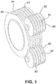
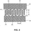
- Die drawing is employed to mechanically draw the material.
- the material is initially extruded into a precursor shape (e.g., profile) and quenched.
- the precursor is then mechanically drawn through a converging die while in a solid state.
- One particularly suitable die drawing process is pultrusion, during which the material is drawn or pulled through the die to form an engineered profile or shape determined by the shape of the die.
- the polymeric material is typically drawn (e.g., in the machine direction) to a draw ratio of from about 1.1 to about 3.5, in some embodiments from about 1.2 to about 3.0, and in some embodiments, from about 1.3 to about 2.5.
- the draw ratio may be determined by dividing the length of the drawn material by its length before drawing.
- the draw rate may also vary to help achieve the desired properties, such as within the range of from about 5% to about 1500% per minute of deformation, in some embodiments from about 20% to about 1000% per minute of deformation, and in some embodiments, from about 25% to about 850% per minute of deformation.
- nanopores such as an average cross-sectional dimension of about 800 nanometers or less, in some embodiments from about 5 to about 250 nanometers, and in some embodiments, from about 10 to about 100 nanometers.
- Micropores may also be formed at and around the micro-scale domains during drawing that have an average cross-sectional dimension of from about 0.5 to about 30 micrometers, in some embodiments from about 1 to about 20 micrometers, and in some embodiments, from about 2 micrometers to about 15 micrometers.
- the micropores and/or nanopores may have any regular or irregular shape, such as spherical, elongated, etc.
- the axial dimension of the micropores and/or nanopores may be larger than the cross-sectional dimension so that the aspect ratio (the ratio of the axial dimension to the cross-sectional dimension) is from about 1 to about 30, in some embodiments from about 1.1 to about 15, and in some embodiments, from about 1.2 to about 5.
- the "axial dimension” is the dimension in the direction of the major axis (e.g., length), which is typically in the direction of drawing.
- the pores can be distributed in a substantially homogeneous fashion throughout the material.
- the pores may be distributed in columns that are oriented in a direction generally perpendicular to the direction in which a stress is applied. These columns may be generally parallel to each other across the width of the material.
- good mechanical properties e.g., energy dissipation under load and impact strength
- the formation of the porous network by the process described above does not necessarily result in a substantial change in the cross-sectional size (e.g., width) of the material.
- the material is not substantially necked, which may allow the material to retain a greater degree of strength properties.
- mechanical drawing can also significantly increase the axial dimension of the micro-scale domains so that they have a generally linear, elongated shape.
- the elongated micro-scale domains may have an average axial dimension that is about 10% or more, in some embodiments from about 20% to about 500%, and in some embodiments, from about 50% to about 250% greater than the axial dimension of the domains prior to drawing.
- the axial dimension after drawing may, for instance, range from about 0.5 to about 250 micrometers, in some embodiments from about 1 to about 100 micrometers, in some embodiments from about 2 to about 50 micrometers, and in some embodiments, from about 5 to about 25 micrometers.
- the micro-scale domains may also be relatively thin and thus have a small cross-sectional dimension.
- the cross-sectional dimension may be from about 0.05 to about 50 micrometers, in some embodiments from about 0.2 to about 10 micrometers, and in some embodiments, from 0.5 to about 5 micrometers. This may result in an aspect ratio for the micro-scale domains (the ratio of the axial dimension to the cross-sectional dimension) of from about 2 to about 150, in some embodiments from about 3 to about 100, and in some embodiments, from about 4 to about 50.
- the polymeric material of the present invention may be subjected to one or more additional processing steps, before and/or after being drawn. Examples of such processes include, for instance, groove roll drawing, embossing, coating, etc.
- the polymeric material may also be annealed to help ensure that it retains the desired shape. Annealing typically occurs at or above the glass transition temperature of the polymer matrix, such as at from about 40°to about 120°C, in some embodiments from about 50°C to about 100°C, and in some embodiments, from about 70°C to about 90°C.
- the polymeric material may also be surface treated using any of a variety of known techniques to improve its properties.
- high energy beams e.g., plasma, x-rays, e-beam, etc.
- plasma x-rays, e-beam, etc.
- e-beam e.g., x-rays, e-beam, etc.
- surface treatment may be used before and/or drawing of the thermoplastic composition.
- the polymeric material of the present invention may generally have a variety of different forms depending on the particular application, such as films, fibrous materials, molded articles, profiles, etc., as well as composites and laminates thereof.
- the polymeric material is in the form of a film or layer of a film.
- Multilayer films may contain from two (2) to fifteen (15) layers, and in some embodiments, from three (3) to twelve (12) layers.
- Such multilayer films normally contain at least one base layer and at least one additional layer (e.g., skin layer), but may contain any number of layers desired.
- the multilayer film may be formed from a base layer and one or more skin layers, wherein the base layer and/or skin layer(s) are formed from the polymeric material of the present invention.
- other polymer materials may also be employed in the base layer and/or skin layer(s), such as polyolefin polymers.
- the thickness of the film may be relatively small to increase flexibility.
- the film may have a thickness of from about 1 to about 200 micrometers, in some embodiments from about 2 to about 150 micrometers, in some embodiments from about 5 to about 100 micrometers, and in some embodiments, from about 10 to about 60 micrometers.
- the film may nevertheless be able to retain good mechanical properties during use.
- the film may be relatively ductile.
- One parameter that is indicative of the ductility of the film is the percent elongation of the film at its break point, as determined by the stress strain curve, such as obtained in accordance with ASTM Standard D638-10 at 23°C.
- the percent elongation at break of the film in the machine direction may be about 10% or more, in some embodiments about 50% or more, in some embodiments about 80% or more, and in some embodiments, from about 100% to about 600%.
- the percent elongation at break of the film in the cross-machine direction may be about 1 5% or more, in some embodiments about 40% or more, in some embodiments about 70% or more, and in some embodiments, from about 1 00% to about 400%.
- Another parameter that is indicative of ductility is the tensile modulus of the film, which is equal to the ratio of the tensile stress to the tensile strain and is determined from the slope of a stress-strain curve.
- the film typically exhibits a MD and/or CD tensile modulus of about 2500 Megapascals ("MPa”) or less, in some embodiments about 2200 MPa or less, in some embodiments from about 50 MPa to about 2000 MPa, and in some embodiments, from about 100 MPa to about 1000 MPa.
- the tensile modulus may be determined in accordance with ASTM D638-10 at 23°C.
- the film is ductile, it can still be relatively strong.
- One parameter that is indicative of the relative strength of the film is the ultimate tensile strength, which is equal to the peak stress obtained in a stress-strain curve, such as obtained in accordance with ASTM Standard D638-10.
- the film may exhibit an MD and/or CD peak stress of from about 5 to about 65 MPa, in some embodiments from about 10 MPa to about 60 MPa, and in some embodiments, from about 20 MPa to about 55 MPa.
- the film may also exhibit an MD and/or CD break stress of from about 5 MPa to about 60 MPa, in some embodiments from about 10 MPa to about 50 MPa, and in some embodiments, from about 20 MPa to about 45 MPa.
- the peak stress and break stress may be determined in accordance with ASTM D638-10 at 23°C.
- the polymeric material may also be in the form of a fibrous material or a layer or component of a fibrous material, which can include individual staple fibers or filaments (continuous fibers), as well as yarns, fabrics, etc. formed from such fibers.
- Yarns may include, for instance, multiple staple fibers that are twisted together ("spun yarn"), filaments laid together without twist ("zero-twist yarn”), filaments laid together with a degree of twist, single filament with or without twist (“monofilament”), etc.
- the yarn may or may not be texturized.
- Suitable fabrics may likewise include, for instance, woven fabrics, knit fabrics, nonwoven fabrics (e.g., spunbond webs, meltblown webs, bonded carded webs, wet-laid webs, airlaid webs, coform webs, hydraulically entangled webs, etc.), and so forth.
- nonwoven fabrics e.g., spunbond webs, meltblown webs, bonded carded webs, wet-laid webs, airlaid webs, coform webs, hydraulically entangled webs, etc.
- Fibers formed from the thermoplastic composition may generally have any desired configuration, including monocomponent and multicomponent (e.g., sheath-core configuration, side-by-side configuration, segmented pie configuration, island-in-the-sea configuration, and so forth).
- the fibers may contain one or more additional polymers as a component (e.g., bicomponent) or constituent (e.g., biconstituent) to further enhance strength and other mechanical properties.
- the thermoplastic composition may form a sheath component of a sheath/core bicomponent fiber, while an additional polymer may form the core component, or vice versa.
- the additional polymer may be a thermoplastic polymer such as polyesters, e.g., polylactic acid, polyethylene terephthalate, polybutylene terephthalate, and so forth; polyolefins, e.g., polyethylene, polypropylene, polybutylene, and so forth; polytetrafluoroethylene; polyvinyl acetate; polyvinyl chloride acetate; polyvinyl butyral; acrylic resins, e.g., polyacrylate, polymethylacrylate, polymethylmethacrylate, and so forth; polyamides, e.g., nylon; polyvinyl chloride; polyvinylidene chloride; polystyrene; polyvinyl alcohol; and polyurethanes.
- polyesters e.g., polylactic acid, polyethylene terephthalate, polybutylene terephthalate, and so forth
- polyolefins e.g., polyethylene, polypropylene, polybutylene,
- the fibers When employed, the fibers can deform upon the application of strain, rather than fracture. The fibers may thus continue to function as a load bearing member even after the fiber has exhibited substantial elongation.
- the fibers of the present invention are capable of exhibiting improved "peak elongation properties, i.e., the percent elongation of the fiber at its peak load.
- the fibers of the present invention may exhibit a peak elongation of about 50% or more, in some embodiments about 100% or more, in some embodiments from about 200% to about 1500%, and in some embodiments, from about 400% to about 800%, such as determined in accordance with ASTM D638-10 at 23°C.
- Such elongations may be achieved for fibers having a wide variety of average diameters, such as those ranging from about 0.1 to about 50 micrometers, in some embodiments from about 1 to about 40 micrometers, in some embodiments from about 2 to about 25 micrometers, and in some embodiments, from about 5 to about 15 micrometers.
- the fibers of the present invention can also remain relatively strong.
- the fibers may exhibit a peak tensile stress of from about 25 to about 500 Megapascals ("MPa”), in some embodiments from about 50 to about 300 MPa, and in some embodiments, from about 60 to about 200 MPa, such as determined in accordance with ASTM D638-10 at 23°C.
- MPa Megapascals
- Another parameter that is indicative of the relative strength of the fibers of the present invention is "tenacity", which indicates the tensile strength of a fiber expressed as force per unit linear density.
- the fibers of the present invention may have a tenacity of from about 0.75 to about 6.0 grams-force ("g f ”) per denier, in some embodiments from about 1.0 to about 4.5 g f per denier, and in some embodiments, from about 1.5 to about 4.0 g f per denier.
- the denier of the fibers may vary depending on the desired application.
- the fibers are formed to have a denier per filament (i.e., the unit of linear density equal to the mass in grams per 9000 meters of fiber) of less than about 6, in some embodiments less than about 3, and in some embodiments, from about 0.5 to about 3.
- the resulting polymeric material of the present invention is well suited for use in a variety of different types of articles, such as an absorbent article, packaging film, barrier film, medical product (e.g., gown, surgical drape, facemask, head covering, surgical cap, shoe covering, sterilization wrap, warming blanket, heating pad, etc.), and so forth.
- the polymeric material may be incorporated into an "absorbent article" that is capable of absorbing water or other fluids.
- absorbent articles examples include, but are not limited to, personal care absorbent articles, such as diapers, training pants, absorbent underpants, incontinence articles, feminine hygiene products (e.g., sanitary napkins), swim wear, baby wipes, mitt wipe, and so forth; medical absorbent articles, such as garments, fenestration materials, underpads, bedpads, bandages, absorbent drapes, and medical wipes; food service wipers; clothing articles; pouches, and so forth. Materials and processes suitable for forming such articles are well known to those skilled in the art.
- Absorbent articles typically include a substantially liquid-impermeable layer (e.g., outer cover), a liquid-permeable layer (e.g., bodyside liner, surge layer, etc.), and an absorbent core.
- the polymeric material may be in the form of a fibrous material (e.g., nonwoven web) and used to form an outer cover of an absorbent article.
- the nonwoven web may be laminated to a liquid-impermeable film that is either vapor-permeable or vapor-impermeable.
- the polymeric material may likewise be in the form of a film that is used in an absorbent article, such as a liquid-impermeable film of the outer cover, which is either vapor-permeable or vapor-impermeable.
- the polymeric material may also be employed in a wide variety of other types of articles.
- Non-limiting examples include, for instance, insulation materials for refrigeration units (e.g., refrigerators, freezers, vending machines, etc.); automotive components (e.g., front and rear seats, headrests, armrests, door panels, rear shelves/package trays, steering wheels and interior trim, dashboards, etc.); building panels and sections (e.g., roofs, wall cavities, under floors, etc.); apparel (e.g., coats, shirts, pants, gloves, aprons, coveralls, shoes, boots, headware, sock liners, etc.); furniture and bedding (e.g., sleeping bags, comforters, etc.); fluid storage/transfer systems (e.g., pipes or tankers for liquid/gas hydrocarbons, liquid nitrogen, oxygen, hydrogen, or crude oil); extreme environments (e.g., underwater or space); food and beverage products (e.g., cups, cup holders, plates, etc.); containers and bottles; and so forth
- the polymeric material may also be used in a "garment”, which is generally meant to include any article that is shaped to fit over a portion of a body.
- articles include, without limitation, clothing (e.g., shirts, pants, jeans, slacks, skirts, coats, activewear, athletic, aerobic, and exercise apparel, swimwear, cycling jerseys or shorts, swimsuit/bathing suit, race suit, wetsuit, bodysuit, etc.), footwear (e.g., shoes, socks, boots, etc.), protective apparel (e.g., firefighter's coat), clothing accessories (e.g., belts, bra straps, side panels, gloves, hosiery, leggings, orthopedic braces, etc.), undergarments (e.g., underwear, t-shirts, etc.), compression garments, draped garments (e.g., kilts loincloths, togas, ponchos, cloaks, shawls, etc.), and so forth.
- clothing e
- the polymeric material may be employed in a wide variety of articles within any particular application.
- the polymeric material may be employed in fibrous articles or as solid moldings.
- fibers of the polymeric material may be beneficially employed in articles that can enhance comfort and/or aesthetics of a vehicle (e.g., coverings and/or paddings for sun visors, speaker housings and coverings, seat coverings, seat slip agents, and backings for seat coverings, carpeting and carpet reinforcement including carpet backing, car mats and backings for car mats, coverings for seat belts and seat belt anchorages, trunk floor coverings and liners, rear shelf panels, headliner facings and backings, upholstery backings, general decorative fabrics, etc.), materials that can provide general temperature and/or noise insulation (e.g., column padding, door trim pads, hood liners, general sound proofing and insulation materials, muffler wraps, bodywork parts, windows, saloon roofs and sunroofs, tire reinforcements, etc.), and filtration/engine
- Solid moldings including the polymeric material can be utilized to enhance automotive safety components.
- the polymeric material can be encompassed in passive safety components such as crumple zones on the rear, front, and/or sides of a vehicle; within the safety cell of the automobile, as a component of the airbag or steering wheel (e.g., a collapsible steering column); as a cargo barrier; or as a component of a pedestrian safety system (e.g., as a component of the bumpers, hood, window frame, etc.).
- the low density of the polymeric material can provide weight saving benefits in automotive applications.
- the polymeric material can be a component of the structure of an automobile including, without limitation, the hood, bumpers and/or bumper supports, the trunk lid and/or compartment, and the underbody of the vehicle.
- the polymeric material can be used in the transportation industry in any suitable application including, without limitation, air and space applications (e.g., airplanes, helicopters, space transports, military aerospace devices, etc.), marine applications (boats, ships, recreational vehicles), trains, and so forth.
- the polymeric material can be utilized in transportation applications in any desired fashion, e.g., in fibrous articles or solid moldings, in aesthetic applications, for temperature and/or noise insulation, in filtration and/or engine components, in safety components, etc.
- Thermal conductivity (W/mK) and thermal resistance (m 2 K/W) were determined in accordance with ASTM E-1530-11 ("Resistance to Thermal Transmission of Materials by the Guarded Heat Flow Meter Technique") using an Anter Unitherm Model 2022 tester.
- the target test temperature was 25°C and the applied load was 0.17 MPa. Prior to testing, the samples were condition for 40+ hours at a temperature of 23°C ( ⁇ 2°C) and relative humidity of 50% ( ⁇ 10%).
- Thermal admittance (W/m 2 K) was also calculated by dividing 1 by the thermal resistance.
- melt flow rate is the weight of a polymer (in grams) forced through an extrusion rheometer orifice (0.0825-inch diameter) when subjected to a load of 2160 grams in 10 minutes, typically at 190°C, 210°C, or 230°C. Unless otherwise indicated, melt flow rate is measured in accordance with ASTM Test Method D1239 with a Tinius Olsen Extrusion Plastometer.
- the glass transition temperature (T g ) may be determined by dynamic mechanical analysis (DMA) in accordance with ASTM E1640-09.
- DMA dynamic mechanical analysis
- ASTM E1640-09 A Q800 instrument from TA Instruments may be used.
- the experimental runs may be executed in tension/tension geometry, in a temperature sweep mode in the range from -120°C to 150°C with a heating rate of 3°C/min.
- the strain amplitude frequency may be kept constant (2 Hz) during the test.
- the melting temperature may be determined by differential scanning calorimetry (DSC).
- DSC differential scanning calorimeter
- the differential scanning calorimeter may be a DSC Q100 Differential Scanning Calorimeter, which may be outfitted with a liquid nitrogen cooling accessory and with a UNIVERSAL ANALYSIS 2000 (version 4.6.6) analysis software program, both of which are available from T.A. Instruments Inc. of New Castle, Delaware.
- tweezers or other tools may be used.
- the samples may be placed into an aluminum pan and weighed to an accuracy of 0.01 milligram on an analytical balance. A lid may be crimped over the material sample onto the pan.
- the resin pellets may be placed directly in the weighing pan.
- the differential scanning calorimeter may be calibrated using an indium metal standard and a baseline correction may be performed, as described in the operating manual for the differential scanning calorimeter.
- a material sample may be placed into the test chamber of the differential scanning calorimeter for testing, and an empty pan may be used as a reference. All testing may be run with a 55-cubic centimeter per minute nitrogen (industrial grade) purge on the test chamber.
- the heating and cooling program is a 2-cycle test that began with an equilibration of the chamber to -30°C, followed by a first heating period at a heating rate of 10°C per minute to a temperature of 200°C, followed by equilibration of the sample at 200°C for 3 minutes, followed by a first cooling period at a cooling rate of 10°C per minute to a temperature of -30°C, followed by equilibration of the sample at -30°C for 3 minutes, and then a second heating period at a heating rate of 10°C per minute to a temperature of 200°C.
- the heating and cooling program may be a 1-cycle test that begins with an equilibration of the chamber to -25°C, followed by a heating period at a heating rate of 10°C per minute to a temperature of 200°C, followed by equilibration of the sample at 200°C for 3 minutes, and then a cooling period at a cooling rate of 10°C per minute to a temperature of -30°C. All testing may be run with a 55-cubic centimeter per minute nitrogen (industrial grade) purge on the test chamber.
- the results may be evaluated using the UNIVERSAL ANALYSIS 2000 analysis software program, which identifies and quantifies the glass transition temperature (T g ) of inflection, the endothermic and exothermic peaks, and the areas under the peaks on the DSC plots.
- T g glass transition temperature
- the glass transition temperature may be identified as the region on the plot-line where a distinct change in slope occurred, and the melting temperature may be determined using an automatic inflection calculation.
- Films may be tested for tensile properties (peak stress, modulus, strain at break, and energy per volume at break) on a MTS Synergie 200 tensile frame.
- the test may be performed in accordance with ASTM D638-10 (at about 23°C).
- Film samples may be cut into dog bone shapes with a center width of 3.0 mm before testing.
- the dog-bone film samples may be held in place using grips on the MTS Synergie 200 device with a gauge length of 18.0 mm.
- the film samples may be stretched at a crosshead speed of 5.0 in/min (0.2 cm/s) until breakage occurred. Five samples may be tested for each film in both the machine direction (MD) and the cross direction (CD).
- a computer program e.g., TestWorks 4
- Fiber tensile properties may be determined in accordance with ASTM 638-10 at 23°C. For instance, individual fiber specimens may initially be shortened (e.g., cut with scissors) to 38 millimeters in length, and placed separately on a black velvet cloth. 10 to 15 fiber specimens may be collected in this manner. The fiber specimens may then be mounted in a substantially straight condition on a rectangular paper frame having external dimension of 51 millimeters x 51 millimeters and internal dimension of 25 millimeters x 25 millimeters. The ends of each fiber specimen may be operatively attached to the frame by carefully securing the fiber ends to the sides of the frame with adhesive tape.
- Each fiber specimen may be measured for its external, relatively shorter, cross-fiber dimension employing a conventional laboratory microscope, which may be properly calibrated and set at 40X magnification. This cross-fiber dimension may be recorded as the diameter of the individual fiber specimen.
- the frame helps to mount the ends of the sample fiber specimens in the upper and lower grips of a constant rate of extension type tensile tester in a manner that avoids excessive damage to the fiber specimens.
- a constant rate of extension type of tensile tester and an appropriate load cell may be employed for the testing.
- the load cell may be chosen (e.g., 10N) so that the test value falls within 10-90% of the full scale load.
- the tensile tester i.e., MTS SYNERGY 200
- load cell may be obtained from MTS Systems Corporation of Eden Prairie, Michigan.
- the fiber specimens in the frame assembly may then be mounted between the grips of the tensile tester such that the ends of the fibers may be operatively held by the grips of the tensile tester. Then, the sides of the paper frame that extend parallel to the fiber length may be cut or otherwise separated so that the tensile tester applies the test force only to the fibers.
- the fibers may be subjected to a pull test at a pull rate and grip speed of 12 inches per minute (0.5 cm/s).
- the resulting data may be analyzed using a TESTWORKS 4 software program from the MTS Corporation with the following test settings: Calculation Inputs Test Inputs Break mark drop 50% Break sensitivity 90% Break marker elongation 0.1 in Break threshold 10 g f Nominal gage length 1 in Data Acq. Rate 10 Hz Slack pre-load 1 lb f Denier length 9000 m Slope segment length 20% Density 1.25 g/cm 3 Yield offset 0.20% Initial speed 12 in/min Yield segment length 2% Secondary speed 2 in/min
- the tenacity values may be expressed in terms of gram-force per denier. Peak elongation (% strain at break) and peak stress may also be measured.
- the width (W i ) and thickness (T i ) of the specimen may be initially measured prior to drawing.
- the length (L i ) before drawing may also be determined by measuring the distance between two markings on a surface of the specimen. Thereafter, the specimen may be drawn to initiate voiding.
- the width (W f ), thickness (T f ), and length (L f ) of the specimen may then be measured to the nearest 0.01 mm utilizing Digimatic Caliper (Mitutoyo Corporation).
- Moisture content may be determined using an Arizona Instruments Computrac Vapor Pro moisture analyzer (Model No. 3100) in substantial accordance with ASTM D 7191-05.
- the test temperature ( ⁇ X2.1.2) may be 130°C
- the sample size ( ⁇ X2.1.1) may be 2 to 4 grams
- the vial purge time ( ⁇ X2.1.4) may be 30 seconds.
- the ending criteria ( ⁇ X2.1.3) may be defined as a "prediction" mode, which means that the test is ended when the built-in programmed criteria (which mathematically calculates the end point moisture content) is satisfied.
- the ability to initiate the formation of pores in a polymeric material was demonstrated. Initially, a blend of 85.3 wt.% polylactic acid (PLA 6201 D, Natureworks®), 9.5 wt.% of a microinclusion additive, 1.4 wt.% of a nanoinclusion additive, and 3.8 wt.% of an interfacial modifier was demonstrated.
- the microinclusion additive was VistamaxxTM 2120 (ExxonMobil), which is a polyolefin copolymer/elastomer with a melt flow rate of 29 g/10 min (190°C, 2160 g) and a density of 0.866 g/cm 3 .
- the nanoinclusion additive was poly(ethylene-co-methyl acrylate-co-glycidyl methacrylate) (Lotader® AX8900, Arkema) having a melt flow rate of 5-6 g/10 min (190°C/2160 g), a glycidyl methacrylate content of 7 to 11 wt.%, methyl acrylate content of 13 to 17 wt.%, and ethylene content of 72 to 80 wt.%, the internal interfacial modifier was PLURIOL® WI 285 Lubricant from BASF which is a Polyalkylene Glycol Functional Fluids.
- the polymers were fed into a co-rotating, twin-screw extruder (ZSK-30, diameter of 30 mm, length of 1328 millimeters) for compounding that was manufactured by Werner and Pfleiderer Corporation of Ramsey, New Jersey.
- the extruder possessed 14 zones, numbered consecutively 1-14 from the feed hopper to the die.
- the first barrel zone #1 received the resins via gravimetric feeder at a total throughput of 15 pounds per hour.
- the PLURIOL® WI285 was added via injector pump into barrel zone #2.
- the die used to extrude the resin had 3 die openings (6 millimeters in diameter) that were separated by 4 millimeters.
- the extruded resin Upon formation, the extruded resin was cooled on a fan-cooled conveyor belt and formed into pellets by a Conair pelletizer.
- the extruder screw speed was 200 revolutions per minute ("rpm").
- the pellets were then flood fed into a signal screw extruder heated to a temperature of 212°C where the molten blend exited through 4.5 inch (11 cm) width slit die and drawn to a film thickness ranging from 0.54 to 0.58 mm.
- Example 1 The sheet produced in Example 1 was cut to a 6" (15 cm) length and then drawn to 100% elongation using a MTS 820 hydraulic tensile frame in tensile mode at 50 mm/min.
- Example 1 The sheet produced in Example 1 was cut to a 6" (15 cm) length and then drawn to 150% elongation using a MTS 820 hydraulic tensile frame in tensile mode at 50 mm/min.
- Example 1 The sheet produced in Example 1 was cut to a 6" length (15 cm) and then drawn to 200% elongation using a MTS 820 hydraulic tensile frame in tensile mode at 50 mm/min.
- Pellets were formed as described in Example 1 and then flood fed into a Rheomix 252 single screw extruder with a L/D ratio of 25:1 and heated to a temperature of 212°C where the molten blend exited through a Haake 6 inch (15cm) width s cast film die and drawn to a film thickness ranging from 39.4 ⁇ m to 50.8 ⁇ m via Haake take-up roll.
- the film was drawn in the machine direction to a longitudinal deformation of 160% at a pull rate of 50 mm/min (deformation rate of 67%/min) via MTS Synergie 200 tensile frame with grips at a gage length of 75 mm.
- Films were formed as described in Example 5, except that the film was also stretched in the cross-machine direction to a deformation of 100% at a pull rate of 50 mm/min (deformation rate of 100%/min) with grips at a gage length of 50 mm.
- Table 1 Film Properties Ex. Average Thickness ( ⁇ m) Expansion Ratio ( ⁇ ) Percent Void Volume (%V v ) Density (g/cm 3 ) 5 41.4 1.82 45 0.65 6 34.0 2.13 53 0.56
- Table 2 Tensile Properties Example Avg. Thickness ( ⁇ m) Avg. Modulus (MPa) Avg. Yield Stress (MPa) Avg. Break Stress (MPa) Avg. Strain at Break (%) Avg.
- Pellets were formed as described in Example 1 and then flood fed into a signal screw extruder heated to a temperature of 212°C, where the molten blend exited through 4.5 inch (11 cm) width slit die and drawn to a film thickness ranging from 36 ⁇ m to 54 ⁇ m.
- the films were stretched in the machine direction to about 100% to initiate cavitation and void formation.
- the morphology of the films was analyzed by scanning electron microscopy (SEM) before and after stretching. The results are shown in Figs. 3-6 . As shown in Figs.
- the microinclusion additive was initially dispersed in domains having an axial size (in machine direction) of from about 2 to about 30 micrometers and a transverse dimension (in cross-machine direction) of from about 1 to about 3 micrometers, while the nanoinclusion additive was initially dispersed as spherical or spheroidal domains having an axial size of from about 100 to about 300 nanometers.
- Figs. 5-6 show the film after stretching.
- the micropores formed around the microinclusion additive generally had an elongated or slit-like shape with a broad size distribution ranging from about 2 to about 20 micrometers in the axial direction.
- the nanopores associated with the nanoinclusion additive generally had a size of from about 50 to about 500 nanometers.
- Example 7 The compounded pellets of Example 7 were dry blended with another nanoinclusion additive, which was a halloisite clay masterbatch (MacroComp MNH-731-36, MacroM) containing 22 wt.% of a styrenic copolymer modified nanoclay and 78 wt.% polypropylene (Exxon Mobil 3155).
- the mixing ratio was 90 wt.% of the pellets and 10 wt.% of the clay masterbatch, which provided a total clay content of 2.2%.
- the dry blend was then flood fed into a signal screw extruder heated to a temperature of 212°C, where the molten blend exited through 4.5 inch (11cm) width slit die and drawn to a film thickness ranging from 51 to 58 ⁇ m.
- the films were stretched in the machine direction to about 100% to initiate cavitation and void formation.
- Figs. 7-10 The morphology of the films was analyzed by scanning electron microscopy (SEM) before and after stretching. The results are shown in Figs. 7-10 . As shown in Figs. 7-8 , some of the nanoclay particles (visible as brighter regions) became dispersed in the form of very small domains - i.e., axial dimension ranging from about 50 to about 300 nanometers. The masterbatch itself also formed domains of a micro-scale size (axial dimension of from about 1 to about 5 micrometers).
- the microinclusion additive (VistamaxTM) formed elongated domains
- the nanoinclusion additives (Lotader®, visible as ultrafine dark dots and nanoclay masterbatch, visible as bright platelets) formed spheroidal domains.
- the stretched film is shown in Figs. 9-10 .
- the voided structure is more open and demonstrates a broad variety of pore sizes.
- the nanoclay masterbatch inclusions formed more open spheroidal micropores with an axial size of about 10 microns or less and a transverse size of about 2 microns.
- Spherical nanopores are also formed by the nanoinclusion additives (Lotader® and nanoclay particles).
- the addition of the nanoclay filler resulted in a slight increase in break stress and a significant increase in elongation at break.
- a precursor blend was formed from 91.8 wt.% isotactic propylene homopolymer (M3661, melt flow rate of 14 g/10 at 210°C and melting temperature of 150°C, Total Petrochemicals), 7.4 wt.% polylactic acid (PLA 6252, melt flow rate of 70 to 85 g/10 min at 210°C, Natureworks®), and 0.7 wt.% of a polyepoxide.
- the polyepoxide was poly(ethylene-co-methyl acrylate-co-glycidyl methacrylate) (LOTADER® AX8900, Arkema) having a melt flow rate of 6 g/10 min (190°C/2160 g), a glycidyl methacrylate content of 8 wt.%, methyl acrylate content of 24 wt.%, and ethylene content of 68 wt.%.
- the temperature in the extruder ranged from 180°C to 220°C.
- the polymer was fed gravimetrically to the extruder at the hoper at 15 pounds per hour and the liquid was injected into the barrel using a peristaltic pump.
- the extruder was operated at 200 revolutions per minute (RPM).
- RPM revolutions per minute
- a 3-hole die of 6 mm in diameter was used to form the extrudate.
- the extrudate was air-cooled in a conveyor belt and pelletized using a Conair Pelletizer.
- Fiber was then produced from the precursor blend using a Davis-Standard fiber spinning line equipped with a 0.75-inch (1.9 cm) single screw extruder and 16 hole spinneret with a diameter of 0.6 mm.
- the fibers were collected at different draw down ratios.
- the take up speed ranged from 1 to 1000 m/min.
- the temperature of the extruder ranged from 175°C to 220°C.
- the fibers were stretched in a tensile tester machine at 300 mm/min up to 400% elongation at 25°C.
- the fibers were freeze fractured in liquid nitrogen and analyzed via Scanning Electron Microscope Jeol 6490LV at high vacuum. The results are shown in Fig. 11-13 .
- nanopores ⁇ 50 nanometers in width, ⁇ 500 nanometers in length
- micropores ⁇ 0.5 micrometers in width, -4 micrometers in length
- Pellets were formed as described in Example 1 and then flood fed into a single screw extruder at 240°C, melted, and passed through a melt pump at a rate of 0.40 grams per hole per minute through a 0.6 mm diameter spinneret. Fibers were collected in free fall (gravity only as draw force) and then tested for mechanical properties at a pull rate of 50 millimeters per minute. Fibers were then cold drawn at 23°C in a MTS Synergie Tensile frame at a rate of 50 mm/min. Fibers were drawn to pre-defined strains of 50%, 100%, 150%, 200% and 250%. After drawing, the expansion ratio, void volume and density were calculated for various strain rates as shown in the tables below.
- Fibers were formed as described in Example 10, except that they were collected at a collection roll speed of 100 meters per minute resulting in a drawn down ratio of 77. Fibers were then tested for mechanical properties at a pull rate of 50 millimeters per minute. Fibers were then cold drawn at 23°C in a MTS Synergie Tensile frame at a rate of 50 mm/min. Fibers were drawn to pre-defined strains of 50%, 100%, 150%, 200% and 250%. After drawing, the expansion ratio, void volume and density were calculated for various strain rates as shown in the tables below.
- Fibers were formed as described in Example 10, except that the blend was composed of 83.7 wt.% polylactic acid (PLA 6201D, Natureworks®), 9.3 wt.% of VistamaxxTM 2120, 1.4 wt.% Lotader® AX8900, 3.7% wt.% PLURIOL® WI 285, and 1.9% hydrophilic surfactant (Masil SF-19).
- the PLURIOL® WI285 and Masil SF-19 were premixed at a 2:1 (WI-285:SF-19) ratio and added via injector pump into barrel zone #2. Fibers were collected at 240°C, 0.40 ghm and under free fall.
- Fibers were formed as described in Example 12, except that they were collected at a collection roll speed of 100 meters per minute resulting in a drawn down ratio of 77. Fibers were then tested for mechanical properties at a pull rate of 50 millimeters per minute. Fibers were then cold drawn at 23°C in a MTS Synergie Tensile frame at a rate of 50 mm/min. Fibers were drawn to pre-defined strain of 100%. After drawing, the expansion ratio, void volume and density were calculated as shown in the tables below.
- Fibers from Example 12 were stretched in a MTS Synergie Tensile frame at a rate of 50 millimeters per minute to 250% strain. This opened up the void structure and turned the fiber white. A one inch sample was then cut from the stressed, white area of the fiber. The new fiber was then tested as described above. The density was estimated to be 0.75 grams per cubic centimeters and the pull rate for the tensile test was 305 mm/min.
- Fibers from Example 11 were heated in an oven at 50°C for 30 minutes to anneal the fiber.
- Fibers from Example 11 were heated in an oven at 90°C for 5 minutes to anneal the fiber and induce crystallization.
- the ability to form films from a blend of 85.3 wt.% polylactic acid (PLA 6201D, Natureworks®), 9.5 wt.% of VistamaxxTM 2120, and 1.4 wt.% Lotader® AX8900 Arkema), and PLURIOL® WI 285 was demonstrated.
- the polymers were fed into a co-rotating, twin-screw extruder that possessed 11 zones, numbered consecutively 1-11 from the feed hopper to the die.
- the first barrel zone #1 received the resins via gravimetric feeder at a total throughput of 500 pounds per hour.
- the PLURIOL® WI285 was added via injector pump into barrel zone #3.
- the molten resin blend was then extruded through a 24-hole die and underwater pelletized.
- the pellets were then flood fed into a signal screw extruder heated to a temperature of 205°C where the molten blend exited through 36 inch (91 cm) width slit die and drawn to a film thickness ranging from 36 ⁇ m to 54 ⁇ m.
- the film was then drawn through a machine direction orientation draw unit consisting of 7 sets of nip rolls through which the material was stretched.
- the film was drawn from 1.3 to 2.2X to initiate and grow the porous structure.
- the process details and resulting density reduction are set forth in the table below.
- the resin from Example 17 was melt spun at 230°C through a spinneret consisting of 675 holes with an orifice size of 0.35 millimeters at a throughput of 0.28 grams per hole per minute. Fibers were melt drawn on a godet roll at a speed of 111 meters per minute and wound on to a bobbin. The bobbin containing the fiber was then drawn from the bobbin on a staple fiber line at a draw ratio ranging from 1.25X to 1.75x and collected as drawn fibers as well as cut into -35 mm. Draw Condition Density Reduction (%) 1 0% 1.25X 20% 1.5X 30% 1.75X 40%
- Fibers were formed as in Example 18 except the fiber had a throughput of 0.36 grams per hole per minute and fibers were drawn on the staple fiber line at 1.25x to 2x.
- Draw Condition Density Reduction (%) 1 0% 1.25X 7% 1.5X 17% 1.75X 23% 2.0X 35%
- Fibers were formed as in Example 19 except the 1 st zone of the staple fiber line was heated from 25°C to 90°C and fibers were drawn from 1.25X to 1.75X Draw Condition Density Reduction (%) 1 0% 1.25X 5% 1.5X 14% 1.75X 15%
- Fibers were formed as in Example 18 except the fiber had a throughput of 0.36 grams per hole per minute and fibers were melt drawn on a godet roll at a speed of 76 meters per minute. Fibers were then drawn on the staple fiber line from and fibers were drawn on the staple fiber line at 1.25x to 2.5x. Draw Condition Density Reduction (%) 1 0% 1.25X 16% 1.5X 28% 1.75X 33% 2.0X 44% 2.5X 55%
Landscapes
- Chemical & Material Sciences (AREA)
- Engineering & Computer Science (AREA)
- Health & Medical Sciences (AREA)
- Chemical Kinetics & Catalysis (AREA)
- Medicinal Chemistry (AREA)
- Polymers & Plastics (AREA)
- Organic Chemistry (AREA)
- Manufacturing & Machinery (AREA)
- Materials Engineering (AREA)
- Mechanical Engineering (AREA)
- Compositions Of Macromolecular Compounds (AREA)
- Manufacture Of Porous Articles, And Recovery And Treatment Of Waste Products (AREA)
Applications Claiming Priority (3)
| Application Number | Priority Date | Filing Date | Title |
|---|---|---|---|
| US201361833989P | 2013-06-12 | 2013-06-12 | |
| US201361907556P | 2013-11-22 | 2013-11-22 | |
| PCT/IB2014/062026 WO2014199275A1 (en) | 2013-06-12 | 2014-06-06 | Pore initiation technique |
Publications (3)
| Publication Number | Publication Date |
|---|---|
| EP3008117A1 EP3008117A1 (en) | 2016-04-20 |
| EP3008117A4 EP3008117A4 (en) | 2017-01-25 |
| EP3008117B1 true EP3008117B1 (en) | 2019-01-16 |
Family
ID=52021718
Family Applications (1)
| Application Number | Title | Priority Date | Filing Date |
|---|---|---|---|
| EP14811094.3A Active EP3008117B1 (en) | 2013-06-12 | 2014-06-06 | Pore initiation technique |
Country Status (11)
| Country | Link |
|---|---|
| US (1) | US10857705B2 (ru) |
| EP (1) | EP3008117B1 (ru) |
| JP (1) | JP2016521786A (ru) |
| KR (1) | KR102208277B1 (ru) |
| CN (1) | CN105263996B (ru) |
| AU (1) | AU2014279702B2 (ru) |
| BR (1) | BR112015029157B1 (ru) |
| MX (1) | MX2015016236A (ru) |
| RU (1) | RU2630792C2 (ru) |
| SG (1) | SG11201510050QA (ru) |
| WO (1) | WO2014199275A1 (ru) |
Families Citing this family (16)
| Publication number | Priority date | Publication date | Assignee | Title |
|---|---|---|---|---|
| US11965083B2 (en) | 2013-06-12 | 2024-04-23 | Kimberly-Clark Worldwide, Inc. | Polyolefin material having a low density |
| BR112015030619B1 (pt) | 2013-06-12 | 2022-02-22 | Kimberly-Clark Worldwide, Inc | Artigo absorvente |
| US11286362B2 (en) | 2013-06-12 | 2022-03-29 | Kimberly-Clark Worldwide, Inc. | Polymeric material for use in thermal insulation |
| KR102224562B1 (ko) | 2013-06-12 | 2021-03-08 | 킴벌리-클라크 월드와이드, 인크. | 복수모드 포어 크기 분포를 갖는 중합체 물질 |
| CN105246443B (zh) | 2013-06-12 | 2019-12-17 | 金伯利-克拉克环球有限公司 | 包含多孔聚烯烃膜的吸收性制品 |
| US11186927B2 (en) | 2014-06-06 | 2021-11-30 | Kimberly Clark Worldwide, Inc. | Hollow porous fibers |
| MX371283B (es) | 2014-06-06 | 2020-01-24 | Kimberly Clark Co | Artículo termoformado a partir de lámina polimérica porosa. |
| WO2016122619A1 (en) | 2015-01-30 | 2016-08-04 | Kimberly-Clark Worldwide, Inc. | Absorbent article package with reduced noise |
| WO2016122621A1 (en) | 2015-01-30 | 2016-08-04 | Kimberly-Clark Worldwide, Inc. | Film with reduced noise for use in an absorbent article |
| US9956985B2 (en) * | 2016-02-16 | 2018-05-01 | Steering Solutions Ip Holding Corporation | Steering shaft assembly |
| WO2018144241A1 (en) * | 2017-01-31 | 2018-08-09 | Kimberly-Clark Worldwide, Inc. | Porous polyester material |
| US10882070B2 (en) | 2017-03-28 | 2021-01-05 | Steering Solutions Ip Holding Corporation | Method of manufacturing a steering shaft assembly |
| CN111534068B (zh) * | 2020-06-02 | 2021-12-10 | 中国科学技术大学 | 一种超高抗冲击强度聚乳酸材料及其制备方法 |
| WO2022169937A1 (en) * | 2021-02-08 | 2022-08-11 | VOID Technologies Limited | Olefin-based polymer composition with voiding agent and article |
| CN113174656B (zh) * | 2021-06-10 | 2022-09-16 | 宁波马菲羊纺织科技有限公司 | 一种生物降解纤维及其制备方法 |
| CN115262788B (zh) * | 2022-07-29 | 2023-08-15 | 深圳市航天新材科技有限公司 | 一种多重尺度孔结构的复合吸声板及其制备方法 |
Family Cites Families (157)
| Publication number | Priority date | Publication date | Assignee | Title |
|---|---|---|---|---|
| US3354506A (en) | 1962-04-30 | 1967-11-28 | Union Carbide Corp | Apparatus for melt extrusion of multi-wall plastic tubing |
| US3423255A (en) | 1965-03-31 | 1969-01-21 | Westinghouse Electric Corp | Semiconductor integrated circuits and method of making the same |
| US3801429A (en) | 1969-06-06 | 1974-04-02 | Dow Chemical Co | Multilayer plastic articles |
| DE1939528A1 (de) | 1969-08-02 | 1971-02-11 | Barmag Barmer Maschf | Vorrichtung zum kontinuierlichen Herstellen von Mehrschichtblasfolien |
| DE2048006B2 (de) | 1969-10-01 | 1980-10-30 | Asahi Kasei Kogyo K.K., Osaka (Japan) | Verfahren und Vorrichtung zur Herstellung einer breiten Vliesbahn |
| CA948388A (en) | 1970-02-27 | 1974-06-04 | Paul B. Hansen | Pattern bonded continuous filament web |
| GB1453447A (en) | 1972-09-06 | 1976-10-20 | Kimberly Clark Co | Nonwoven thermoplastic fabric |
| US4100324A (en) | 1974-03-26 | 1978-07-11 | Kimberly-Clark Corporation | Nonwoven fabric and method of producing same |
| US4289832A (en) * | 1975-03-31 | 1981-09-15 | Biax Fiberfilm Corp. | Chemically-impregnated microporous films |
| US4116892A (en) * | 1975-03-31 | 1978-09-26 | Biax-Fiberfilm Corporation | Process for stretching incremental portions of an orientable thermoplastic substrate and product thereof |
| US4153751A (en) * | 1975-03-31 | 1979-05-08 | Biax-Fiberfilm Corporation | Process for stretching an impregnated film of material and the microporous product produced thereby |
| US4282735A (en) | 1979-04-02 | 1981-08-11 | Van Mark Products Corporation | Brake for sheet metal or the like |
| US4374888A (en) | 1981-09-25 | 1983-02-22 | Kimberly-Clark Corporation | Nonwoven laminate for recreation fabric |
| US4937299A (en) | 1983-06-06 | 1990-06-26 | Exxon Research & Engineering Company | Process and catalyst for producing reactor blend polyolefins |
| US4557132A (en) | 1984-02-03 | 1985-12-10 | Tapco Products Company, Inc. | Sheet bending brake |
| CA1341430C (en) | 1984-07-02 | 2003-06-03 | Kenneth Maynard Enloe | Diapers with elasticized side pockets |
| US4698372A (en) | 1985-09-09 | 1987-10-06 | E. I. Du Pont De Nemours And Company | Microporous polymeric films and process for their manufacture |
| ES2052551T3 (es) | 1986-12-19 | 1994-07-16 | Akzo Nv | Metodo para preparar poli(acido lactico) o copolimeros de poli(acido lactico) por polimeracion de la lactida. |
| US4908026A (en) | 1986-12-22 | 1990-03-13 | Kimberly-Clark Corporation | Flow distribution system for absorbent pads |
| US4766029A (en) | 1987-01-23 | 1988-08-23 | Kimberly-Clark Corporation | Semi-permeable nonwoven laminate |
| US4801494A (en) | 1987-04-10 | 1989-01-31 | Kimberly-Clark Corporation | Nonwoven pad cover with fluid masking properties |
| US4798603A (en) | 1987-10-16 | 1989-01-17 | Kimberly-Clark Corporation | Absorbent article having a hydrophobic transport layer |
| US5179164A (en) | 1988-02-20 | 1993-01-12 | Basf Aktiengesellschaft | Thermoplastic polypropylene/polyamide molding composition |
| JPH0214011A (ja) | 1988-06-27 | 1990-01-18 | Mitsubishi Rayon Co Ltd | 多孔質ポリエチレン繊維 |
| USD315990S (en) | 1988-08-04 | 1991-04-09 | Kimberly-Clark Corporation | Embossed wipe or similar article |
| US5218071A (en) | 1988-12-26 | 1993-06-08 | Mitsui Petrochemical Industries, Ltd. | Ethylene random copolymers |
| US5169706A (en) | 1990-01-10 | 1992-12-08 | Kimberly-Clark Corporation | Low stress relaxation composite elastic material |
| US5464688A (en) | 1990-06-18 | 1995-11-07 | Kimberly-Clark Corporation | Nonwoven web laminates with improved barrier properties |
| US5213881A (en) | 1990-06-18 | 1993-05-25 | Kimberly-Clark Corporation | Nonwoven web with improved barrier properties |
| US5272236A (en) | 1991-10-15 | 1993-12-21 | The Dow Chemical Company | Elastic substantially linear olefin polymers |
| US5248309A (en) | 1990-07-19 | 1993-09-28 | Kimberly-Clark Corporation | Thin sanitary napkin having a central absorbent zone and a method of forming the napkin |
| CA2048905C (en) | 1990-12-21 | 1998-08-11 | Cherie H. Everhart | High pulp content nonwoven composite fabric |
| US5192606A (en) | 1991-09-11 | 1993-03-09 | Kimberly-Clark Corporation | Absorbent article having a liner which exhibits improved softness and dryness, and provides for rapid uptake of liquid |
| US5278272A (en) | 1991-10-15 | 1994-01-11 | The Dow Chemical Company | Elastic substantialy linear olefin polymers |
| US5743129A (en) | 1991-11-26 | 1998-04-28 | Tapco International Corporation | Heavy duty sheet bending brake |
| US6326458B1 (en) | 1992-01-24 | 2001-12-04 | Cargill, Inc. | Continuous process for the manufacture of lactide and lactide polymers |
| US5470944A (en) | 1992-02-13 | 1995-11-28 | Arch Development Corporation | Production of high molecular weight polylactic acid |
| US5350624A (en) | 1992-10-05 | 1994-09-27 | Kimberly-Clark Corporation | Abrasion resistant fibrous nonwoven composite structure |
| US5322728A (en) | 1992-11-24 | 1994-06-21 | Exxon Chemical Patents, Inc. | Fibers of polyolefin polymers |
| US5284309A (en) | 1992-12-18 | 1994-02-08 | Hughes Aircraft Company | Propellant immobilizing system and method |
| IT1256260B (it) | 1992-12-30 | 1995-11-29 | Montecatini Tecnologie Srl | Polipropilene atattico |
| CA2114663A1 (en) | 1993-02-05 | 1994-08-06 | Joshua B. Sweeney | Microporous polymer structures |
| US5472775A (en) | 1993-08-17 | 1995-12-05 | The Dow Chemical Company | Elastic materials and articles therefrom |
| US6093665A (en) | 1993-09-30 | 2000-07-25 | Kimberly-Clark Worldwide, Inc. | Pattern bonded nonwoven fabrics |
| CA2116081C (en) | 1993-12-17 | 2005-07-26 | Ann Louise Mccormack | Breathable, cloth-like film/nonwoven composite |
| CA2123330C (en) | 1993-12-23 | 2004-08-31 | Ruth Lisa Levy | Ribbed clothlike nonwoven fabric and process for making same |
| USD358035S (en) | 1994-01-10 | 1995-05-09 | Kimberly-Clark Corporation | Embossed wipe |
| US5486166A (en) | 1994-03-04 | 1996-01-23 | Kimberly-Clark Corporation | Fibrous nonwoven web surge layer for personal care absorbent articles and the like |
| ES2136214T3 (es) | 1994-03-04 | 1999-11-16 | Kimberly Clark Co | Tela no tejida fibrosa con control mejorado de derramamiento de liquido para articulos absorbentes de higiene personal y similares. |
| US5571619A (en) | 1994-05-24 | 1996-11-05 | Exxon Chemical Patents, Inc. | Fibers and oriented films of polypropylene higher α-olefin copolymers |
| US5702377A (en) | 1994-09-01 | 1997-12-30 | Kimberly-Clark Worldwide, Inc. | Wet liner for child toilet training aid |
| US5539056A (en) | 1995-01-31 | 1996-07-23 | Exxon Chemical Patents Inc. | Thermoplastic elastomers |
| EP0755956B1 (en) | 1995-07-25 | 2004-01-14 | Toyota Jidosha Kabushiki Kaisha | Method for producing polylactic acid |
| US5770682A (en) | 1995-07-25 | 1998-06-23 | Shimadzu Corporation | Method for producing polylactic acid |
| CN1203609A (zh) | 1995-12-01 | 1998-12-30 | 希巴特殊化学控股公司 | 聚(9,9'-螺双芴),其制备和其应用 |
| US6060638A (en) | 1995-12-22 | 2000-05-09 | Kimberly-Clark Worldwide, Inc. | Matched permeability liner/absorbent structure system for absorbent articles and the like |
| USD384819S (en) | 1996-03-22 | 1997-10-14 | Kimberly-Clark Corporation | Top surface of a wipe |
| JP3588907B2 (ja) | 1996-03-22 | 2004-11-17 | トヨタ自動車株式会社 | ポリ乳酸の製造方法 |
| WO1998001293A1 (en) | 1996-07-08 | 1998-01-15 | Oceaneering Space Systems, A Division Of Oceaneering International, Inc. | Insulation panel |
| US5843057A (en) | 1996-07-15 | 1998-12-01 | Kimberly-Clark Worldwide, Inc. | Film-nonwoven laminate containing an adhesively-reinforced stretch-thinned film |
| US5766760A (en) | 1996-09-04 | 1998-06-16 | Kimberly-Clark Worldwide, Inc. | Microporous fibers with improved properties |
| USD384508S (en) | 1996-08-22 | 1997-10-07 | Kimberly-Clark Worldwide, Inc. | Wipe |
| USD390708S (en) | 1996-10-31 | 1998-02-17 | Kimberly-Clark Worldwide, Inc. | Pattern for a bonded fabric |
| US5962112A (en) | 1996-12-19 | 1999-10-05 | Kimberly-Clark Worldwide, Inc. | Wipers comprising point unbonded webs |
| US6111163A (en) | 1996-12-27 | 2000-08-29 | Kimberly-Clark Worldwide, Inc. | Elastomeric film and method for making the same |
| TW526066B (en) | 1996-12-27 | 2003-04-01 | Kimberly Clark Co | Stable and breathable films of improved toughness, their products, and the method of making the same |
| US6037281A (en) | 1996-12-27 | 2000-03-14 | Kimberly-Clark Worldwide, Inc. | Cloth-like, liquid-impervious, breathable composite barrier fabric |
| US6015764A (en) | 1996-12-27 | 2000-01-18 | Kimberly-Clark Worldwide, Inc. | Microporous elastomeric film/nonwoven breathable laminate and method for making the same |
| US5947944A (en) | 1996-12-30 | 1999-09-07 | Kimberly-Clark Worldwide, Inc. | Stretched-thinned films comprising low crystallinity polymers and laminates thereof |
| US5912076A (en) | 1996-12-31 | 1999-06-15 | Kimberly-Clark Worldwide, Inc. | Blends of polyethylene and peo having inverse phase morphology and method of making the blends |
| US5931823A (en) | 1997-03-31 | 1999-08-03 | Kimberly-Clark Worldwide, Inc. | High permeability liner with improved intake and distribution |
| US5997981A (en) | 1997-09-15 | 1999-12-07 | Kimberly-Clark Worldwide, Inc. | Breathable barrier composite useful as an ideal loop fastener component |
| US5932497A (en) | 1997-09-15 | 1999-08-03 | Kimberly-Clark Worldwide, Inc. | Breathable elastic film and laminate |
| US5968643A (en) * | 1997-09-16 | 1999-10-19 | Kimberly-Clark Worldwide, Inc. | Microporous film with improved properties |
| US5800758A (en) * | 1997-09-16 | 1998-09-01 | Kimberly-Clark Worldwide, Inc. | Process for making microporous films with improved properties |
| US6090325A (en) | 1997-09-24 | 2000-07-18 | Fina Technology, Inc. | Biaxially-oriented metallocene-based polypropylene films |
| US6197404B1 (en) | 1997-10-31 | 2001-03-06 | Kimberly-Clark Worldwide, Inc. | Creped nonwoven materials |
| US6277479B1 (en) | 1997-12-19 | 2001-08-21 | Kimberly-Clark Worldwide, Inc. | Microporous films having zoned breathability |
| US6071451A (en) | 1997-12-31 | 2000-06-06 | Kimberly-Clark Worldwide, Inc. | Process for making a nonwoven, porous fabric from polymer composite materials |
| US6245401B1 (en) * | 1999-03-12 | 2001-06-12 | Kimberly-Clark Worldwide, Inc. | Segmented conformable breathable films |
| USD418305S (en) | 1998-09-24 | 2000-01-04 | Kimberly-Clark Worldwide, Inc. | Wipe |
| US6368444B1 (en) * | 1998-11-17 | 2002-04-09 | Kimberly-Clark Worldwide, Inc. | Apparatus and method for cross-directional stretching of polymeric film and other nonwoven sheet material and materials produced therefrom |
| AR022137A1 (es) | 1998-12-31 | 2002-09-04 | Kimberly Clark Co | Una composicion de materia, una pelicula y un articulo que comprenden dicha composicion |
| AR022140A1 (es) * | 1998-12-31 | 2002-09-04 | Kimberly Clark Co | Una composicion de materia, una pelicula y un articulo que comprenden dicha composicion y el proceso para hacer dicha composicion |
| US6586073B2 (en) * | 1999-05-07 | 2003-07-01 | 3M Innovative Properties Company | Films having a microfibrillated surface and method of making |
| US6500563B1 (en) | 1999-05-13 | 2002-12-31 | Exxonmobil Chemical Patents Inc. | Elastic films including crystalline polymer and crystallizable polymers of propylene |
| US6461457B1 (en) | 1999-06-30 | 2002-10-08 | Kimberly-Clark Worldwide, Inc. | Dimensionally stable, breathable, stretch-thinned, elastic films |
| US6642429B1 (en) | 1999-06-30 | 2003-11-04 | Kimberly-Clark Worldwide, Inc. | Personal care articles with reduced polymer fibers |
| USD428267S (en) | 1999-08-27 | 2000-07-18 | Kimberly-Clark Worldwide, Inc. | Repeating pattern for a bonded fabric |
| US6663611B2 (en) | 1999-09-28 | 2003-12-16 | Kimberly-Clark Worldwide, Inc. | Breathable diaper with low to moderately breathable inner laminate and more breathable outer cover |
| US6794024B1 (en) * | 1999-11-01 | 2004-09-21 | Kimberly-Clark Worldwide, Inc. | Styrenic block copolymer breathable elastomeric films |
| JP2001233982A (ja) | 1999-12-14 | 2001-08-28 | Tokuyama Corp | 多孔質ポリオレフィンフィルム及びその製造方法 |
| US6234988B1 (en) | 1999-12-15 | 2001-05-22 | I-Tek, Inc. | Heel locking, energy absorbing, support and cushioning device |
| US20020098341A1 (en) * | 2000-12-07 | 2002-07-25 | Schiffer Daniel K. | Biodegradable breathable film and laminate |
| US6582810B2 (en) | 2000-12-22 | 2003-06-24 | Kimberly-Clark Worldwide, Inc. | One-step method of producing an elastic, breathable film structure |
| US6824680B2 (en) | 2001-05-07 | 2004-11-30 | New Jersey Institute Of Technology | Preparation of microporous films from immiscible blends via melt processing and stretching |
| US6824734B2 (en) | 2001-10-09 | 2004-11-30 | Kimberly-Clark Worldwide, Inc. | Method of producing latent elastic, cross-direction-oriented films |
| US6716203B2 (en) | 2001-12-18 | 2004-04-06 | Kimberly-Clark Worldwide, Inc. | Individual absorbent articles wrapped in a quiet and soft package |
| US20030116462A1 (en) | 2001-12-20 | 2003-06-26 | Kimberly-Clark Worldwide, Inc. | Pouch configuration for wrapped absorbent articles |
| US20040002273A1 (en) | 2002-07-01 | 2004-01-01 | Kimberly-Clark Worldwide, Inc. | Liquid repellent nonwoven protective material |
| WO2004013388A1 (ja) | 2002-08-05 | 2004-02-12 | Toray Industries, Inc. | 多孔繊維 |
| US7998579B2 (en) | 2002-08-12 | 2011-08-16 | Exxonmobil Chemical Patents Inc. | Polypropylene based fibers and nonwovens |
| US7341776B1 (en) | 2002-10-03 | 2008-03-11 | Milliren Charles M | Protective foam with skin |
| US6958860B2 (en) * | 2002-10-07 | 2005-10-25 | Eastman Kodak Company | Voided polymer film containing layered particulates |
| EP1564315B1 (en) | 2002-10-23 | 2011-12-07 | Toray Industries, Inc. | Nanofiber aggregate, polymer alloy fiber, hybrid fiber, fibrous structures, and processes for production of them |
| US7060867B2 (en) | 2002-11-27 | 2006-06-13 | Kimberly-Clark Worldwide, Inc. | Absorbent article with a body facing liner having discretely placed lotion deposits |
| US7220478B2 (en) * | 2003-08-22 | 2007-05-22 | Kimberly-Clark Worldwide, Inc. | Microporous breathable elastic films, methods of making same, and limited use or disposable product applications |
| US7270723B2 (en) * | 2003-11-07 | 2007-09-18 | Kimberly-Clark Worldwide, Inc. | Microporous breathable elastic film laminates, methods of making same, and limited use or disposable product applications |
| US7179952B2 (en) * | 2003-08-25 | 2007-02-20 | Kimberly-Clark Worldwide, Inc. | Absorbent article formed with microlayered films |
| US20050054255A1 (en) | 2003-09-08 | 2005-03-10 | Kimberly-Clark Worldwide, Inc. | Nonwoven fabric liner and diaper including a nonwoven laminate liner |
| US20050059941A1 (en) | 2003-09-11 | 2005-03-17 | Kimberly-Clark Worldwide, Inc. | Absorbent product with improved liner treatment |
| DE10348876B4 (de) | 2003-10-21 | 2014-04-03 | Jnc Corporation | Poröse Polyolefinmembran |
| US20050119359A1 (en) | 2003-12-02 | 2005-06-02 | Shelby Marcus D. | Void-containing polyester shrink film |
| US20050245162A1 (en) | 2004-04-30 | 2005-11-03 | Kimberly-Clark Worldwide, Inc. | Multi-capable elastic laminate process |
| US20050241750A1 (en) * | 2004-04-30 | 2005-11-03 | Kimberly-Clark Worldwide, Inc. | Method and apparatus for making extensible and stretchable laminates |
| WO2006002440A2 (en) | 2004-06-29 | 2006-01-05 | Aspen Aerogels, Inc. | Energy efficient and insulated building envelopes |
| US8603614B2 (en) | 2004-07-26 | 2013-12-10 | Borgwarner Inc. | Porous friction material with nanoparticles of friction modifying material |
| US20060147685A1 (en) * | 2004-12-30 | 2006-07-06 | Kimberly-Clark Worldwide, Inc. | Multilayer film structure with higher processability |
| US20060148361A1 (en) * | 2004-12-30 | 2006-07-06 | Kimberley-Clark Worldwide, Inc. | Method for forming an elastic laminate |
| US7943218B2 (en) * | 2006-08-14 | 2011-05-17 | Frito-Lay North America, Inc. | Environmentally-friendly multi-layer flexible film having barrier properties |
| KR101249120B1 (ko) * | 2006-08-31 | 2013-03-29 | 킴벌리-클라크 월드와이드, 인크. | 고도 통기성 생분해성 필름 |
| US7803244B2 (en) * | 2006-08-31 | 2010-09-28 | Kimberly-Clark Worldwide, Inc. | Nonwoven composite containing an apertured elastic film |
| CN101553607A (zh) | 2006-09-01 | 2009-10-07 | 加利福尼亚大学董事会 | 热塑性聚合物微纤维、纳米纤维以及复合材料 |
| JP2008144039A (ja) * | 2006-12-11 | 2008-06-26 | Asahi Kasei Chemicals Corp | 微細通流体性多孔体及びその製造方法 |
| JP5309628B2 (ja) | 2007-03-23 | 2013-10-09 | 住友化学株式会社 | 多孔質フィルム |
| FI124718B (fi) * | 2007-06-01 | 2014-12-31 | Upm Raflatac Oy | Muovietiketti |
| US7984591B2 (en) | 2007-08-10 | 2011-07-26 | Fiberweb, Inc. | Impact resistant sheet material |
| CN101925708B (zh) | 2008-01-23 | 2012-02-22 | 陶氏环球技术公司 | 包含外部蒸汽渗透性泡沫体隔热材料的建筑结构体和用于将建筑结构体隔热的方法 |
| CN102046861B (zh) | 2008-05-30 | 2012-12-12 | 金伯利-克拉克环球有限公司 | 聚乳酸纤维 |
| WO2009152021A2 (en) | 2008-06-13 | 2009-12-17 | The Procter & Gamble Company | Absorbent article with absorbent polymer material, wetness indicator, and reduced migration of surfactant |
| US20090318884A1 (en) | 2008-06-20 | 2009-12-24 | Axel Meyer | Absorbent structures with immobilized absorbent material |
| US8679992B2 (en) * | 2008-06-30 | 2014-03-25 | Kimberly-Clark Worldwide, Inc. | Elastic composite formed from multiple laminate structures |
| US8759446B2 (en) * | 2008-06-30 | 2014-06-24 | Fina Technology, Inc. | Compatibilized polypropylene and polylactic acid blends and methods of making and using same |
| WO2010059448A1 (en) * | 2008-11-24 | 2010-05-27 | Exxonmobil Oil Corporation | Cavitated polymeric films |
| US20100305529A1 (en) | 2009-06-02 | 2010-12-02 | Gregory Ashton | Absorbent Article With Absorbent Polymer Material, Wetness Indicator, And Reduced Migration Of Surfactant |
| US9345802B2 (en) | 2009-06-25 | 2016-05-24 | The Procter & Gamble Company | Absorbent article with barrier component |
| US8313818B2 (en) | 2009-07-29 | 2012-11-20 | Dow Global Technologies Llc | Thermal insulating panel composite |
| WO2011047252A1 (en) | 2009-10-16 | 2011-04-21 | E. I. Du Pont De Nemours And Company | Monolithic films having zoned breathability |
| JP5856974B2 (ja) | 2009-11-25 | 2016-02-10 | ダウ グローバル テクノロジーズ エルエルシー | 高い空隙率を有するナノ多孔質ポリマー発泡体 |
| US8435631B2 (en) | 2010-04-15 | 2013-05-07 | Ppg Industries Ohio, Inc. | Microporous material |
| US10753023B2 (en) | 2010-08-13 | 2020-08-25 | Kimberly-Clark Worldwide, Inc. | Toughened polylactic acid fibers |
| US8936740B2 (en) * | 2010-08-13 | 2015-01-20 | Kimberly-Clark Worldwide, Inc. | Modified polylactic acid fibers |
| JP2010280921A (ja) * | 2010-09-24 | 2010-12-16 | Toray Ind Inc | 白色ポリ乳酸フィルム |
| US20120251771A1 (en) * | 2011-04-04 | 2012-10-04 | Lenox Wilson | Method of making a smooth elastic nonwoven composite |
| JP5755016B2 (ja) * | 2011-04-28 | 2015-07-29 | 株式会社林技術研究所 | 発泡樹脂成形体 |
| US9040598B2 (en) | 2012-02-10 | 2015-05-26 | Kimberly-Clark Worldwide, Inc. | Renewable polyester compositions having a low density |
| US10858762B2 (en) | 2012-02-10 | 2020-12-08 | Kimberly-Clark Worldwide, Inc. | Renewable polyester fibers having a low density |
| US20130210621A1 (en) * | 2012-02-10 | 2013-08-15 | Kimberly-Clark Worldwide, Inc. | Breathable Film Formed from a Renewable Polyester |
| US20140308500A1 (en) * | 2013-04-12 | 2014-10-16 | Heritage Plastics, Inc. | Mineral filled polymer compounds for the production of flexible plastic film and sheet substrates with improved yield |
| RU2605179C1 (ru) | 2013-06-12 | 2016-12-20 | Кимберли-Кларк Ворлдвайд, Инк. | Предмет одежды, содержащий пористый полимерный материал |
| US11286362B2 (en) | 2013-06-12 | 2022-03-29 | Kimberly-Clark Worldwide, Inc. | Polymeric material for use in thermal insulation |
| MX363276B (es) | 2013-06-12 | 2019-03-15 | Kimberly Clark Co | Tejido multifuncional. |
| KR102224562B1 (ko) | 2013-06-12 | 2021-03-08 | 킴벌리-클라크 월드와이드, 인크. | 복수모드 포어 크기 분포를 갖는 중합체 물질 |
| EP3008260A4 (en) | 2013-06-12 | 2017-03-15 | Kimberly-Clark Worldwide, Inc. | Building insulation |
| BR112015030619B1 (pt) | 2013-06-12 | 2022-02-22 | Kimberly-Clark Worldwide, Inc | Artigo absorvente |
| CN105246443B (zh) | 2013-06-12 | 2019-12-17 | 金伯利-克拉克环球有限公司 | 包含多孔聚烯烃膜的吸收性制品 |
| BR112015030878B1 (pt) | 2013-06-12 | 2020-12-15 | Kimberly-Clark Worldwide, Inc. | Membro de absorção de energia, e, equipamento de proteção |
-
2014
- 2014-06-06 AU AU2014279702A patent/AU2014279702B2/en active Active
- 2014-06-06 SG SG11201510050QA patent/SG11201510050QA/en unknown
- 2014-06-06 CN CN201480029212.0A patent/CN105263996B/zh active Active
- 2014-06-06 WO PCT/IB2014/062026 patent/WO2014199275A1/en active Application Filing
- 2014-06-06 MX MX2015016236A patent/MX2015016236A/es active IP Right Grant
- 2014-06-06 BR BR112015029157-0A patent/BR112015029157B1/pt active IP Right Grant
- 2014-06-06 KR KR1020157036860A patent/KR102208277B1/ko active IP Right Grant
- 2014-06-06 EP EP14811094.3A patent/EP3008117B1/en active Active
- 2014-06-06 US US14/895,083 patent/US10857705B2/en active Active
- 2014-06-06 RU RU2015155673A patent/RU2630792C2/ru active
- 2014-06-06 JP JP2016518610A patent/JP2016521786A/ja not_active Withdrawn
Non-Patent Citations (1)
| Title |
|---|
| None * |
Also Published As
| Publication number | Publication date |
|---|---|
| CN105263996A (zh) | 2016-01-20 |
| US20160121523A1 (en) | 2016-05-05 |
| RU2015155673A (ru) | 2017-07-12 |
| JP2016521786A (ja) | 2016-07-25 |
| AU2014279702A1 (en) | 2016-01-21 |
| AU2014279702B2 (en) | 2017-06-22 |
| BR112015029157B1 (pt) | 2020-12-29 |
| SG11201510050QA (en) | 2016-01-28 |
| MX2015016236A (es) | 2016-03-01 |
| US10857705B2 (en) | 2020-12-08 |
| WO2014199275A1 (en) | 2014-12-18 |
| CN105263996B (zh) | 2018-10-09 |
| RU2630792C2 (ru) | 2017-09-13 |
| KR20160020447A (ko) | 2016-02-23 |
| EP3008117A1 (en) | 2016-04-20 |
| BR112015029157A2 (pt) | 2017-07-25 |
| EP3008117A4 (en) | 2017-01-25 |
| KR102208277B1 (ko) | 2021-01-27 |
Similar Documents
| Publication | Publication Date | Title |
|---|---|---|
| EP3008117B1 (en) | Pore initiation technique | |
| EP3008119B1 (en) | Polymeric material with a multimodal pore size distribution | |
| EP3008116B1 (en) | Polyolefin material having a low density | |
| EP3008231B1 (en) | Multi-functional fabric | |
| EP3007575B1 (en) | Garment containing a porous polymeric material | |
| EP3008120B1 (en) | Polymeric material for use in thermal insulation | |
| EP3030606B1 (en) | Anisotropic polymeric material | |
| EP3030607B1 (en) | Technique for selectively controlling the porosity of a polymeric material | |
| EP3030605B1 (en) | Flexible polymeric material with shape retention properties | |
| US11965083B2 (en) | Polyolefin material having a low density |
Legal Events
| Date | Code | Title | Description |
|---|---|---|---|
| PUAI | Public reference made under article 153(3) epc to a published international application that has entered the european phase |
Free format text: ORIGINAL CODE: 0009012 |
|
| 17P | Request for examination filed |
Effective date: 20160112 |
|
| AK | Designated contracting states |
Kind code of ref document: A1 Designated state(s): AL AT BE BG CH CY CZ DE DK EE ES FI FR GB GR HR HU IE IS IT LI LT LU LV MC MK MT NL NO PL PT RO RS SE SI SK SM TR |
|
| AX | Request for extension of the european patent |
Extension state: BA ME |
|
| DAX | Request for extension of the european patent (deleted) | ||
| A4 | Supplementary search report drawn up and despatched |
Effective date: 20161222 |
|
| RIC1 | Information provided on ipc code assigned before grant |
Ipc: C08J 3/20 20060101ALI20161216BHEP Ipc: B29C 44/20 20060101ALI20161216BHEP Ipc: B29C 55/18 20060101AFI20161216BHEP Ipc: B29K 105/16 20060101ALN20161216BHEP Ipc: B29C 44/30 20060101ALI20161216BHEP Ipc: C08J 9/00 20060101ALI20161216BHEP Ipc: C08J 5/18 20060101ALI20161216BHEP Ipc: B29K 105/04 20060101ALN20161216BHEP Ipc: B29C 55/00 20060101ALI20161216BHEP Ipc: C08K 7/00 20060101ALI20161216BHEP Ipc: C08L 23/00 20060101ALI20161216BHEP |
|
| STAA | Information on the status of an ep patent application or granted ep patent |
Free format text: STATUS: EXAMINATION IS IN PROGRESS |
|
| 17Q | First examination report despatched |
Effective date: 20180102 |
|
| REG | Reference to a national code |
Ref country code: DE Ref legal event code: R079 Ref document number: 602014040092 Country of ref document: DE Free format text: PREVIOUS MAIN CLASS: C08J0009000000 Ipc: B29C0055180000 |
|
| GRAP | Despatch of communication of intention to grant a patent |
Free format text: ORIGINAL CODE: EPIDOSNIGR1 |
|
| STAA | Information on the status of an ep patent application or granted ep patent |
Free format text: STATUS: GRANT OF PATENT IS INTENDED |
|
| RIC1 | Information provided on ipc code assigned before grant |
Ipc: C08J 5/18 20060101ALI20180628BHEP Ipc: C08J 3/20 20060101ALI20180628BHEP Ipc: B29K 105/04 20060101ALN20180628BHEP Ipc: C08K 7/00 20060101ALI20180628BHEP Ipc: B29K 105/16 20060101ALN20180628BHEP Ipc: C08L 23/12 20060101ALI20180628BHEP Ipc: C08J 9/00 20060101ALI20180628BHEP Ipc: C08L 23/00 20060101ALI20180628BHEP Ipc: B29C 55/00 20060101ALI20180628BHEP Ipc: B29C 44/20 20060101ALI20180628BHEP Ipc: B29C 55/18 20060101AFI20180628BHEP Ipc: B29C 44/30 20060101ALI20180628BHEP |
|
| INTG | Intention to grant announced |
Effective date: 20180724 |
|
| GRAS | Grant fee paid |
Free format text: ORIGINAL CODE: EPIDOSNIGR3 |
|
| GRAA | (expected) grant |
Free format text: ORIGINAL CODE: 0009210 |
|
| STAA | Information on the status of an ep patent application or granted ep patent |
Free format text: STATUS: THE PATENT HAS BEEN GRANTED |
|
| AK | Designated contracting states |
Kind code of ref document: B1 Designated state(s): AL AT BE BG CH CY CZ DE DK EE ES FI FR GB GR HR HU IE IS IT LI LT LU LV MC MK MT NL NO PL PT RO RS SE SI SK SM TR |
|
| REG | Reference to a national code |
Ref country code: GB Ref legal event code: FG4D |
|
| REG | Reference to a national code |
Ref country code: CH Ref legal event code: EP |
|
| REG | Reference to a national code |
Ref country code: IE Ref legal event code: FG4D |
|
| REG | Reference to a national code |
Ref country code: DE Ref legal event code: R096 Ref document number: 602014040092 Country of ref document: DE |
|
| REG | Reference to a national code |
Ref country code: AT Ref legal event code: REF Ref document number: 1089391 Country of ref document: AT Kind code of ref document: T Effective date: 20190215 |
|
| REG | Reference to a national code |
Ref country code: NL Ref legal event code: MP Effective date: 20190116 |
|
| REG | Reference to a national code |
Ref country code: LT Ref legal event code: MG4D |
|
| PG25 | Lapsed in a contracting state [announced via postgrant information from national office to epo] |
Ref country code: NL Free format text: LAPSE BECAUSE OF FAILURE TO SUBMIT A TRANSLATION OF THE DESCRIPTION OR TO PAY THE FEE WITHIN THE PRESCRIBED TIME-LIMIT Effective date: 20190116 |
|
| PG25 | Lapsed in a contracting state [announced via postgrant information from national office to epo] |
Ref country code: FI Free format text: LAPSE BECAUSE OF FAILURE TO SUBMIT A TRANSLATION OF THE DESCRIPTION OR TO PAY THE FEE WITHIN THE PRESCRIBED TIME-LIMIT Effective date: 20190116 Ref country code: SE Free format text: LAPSE BECAUSE OF FAILURE TO SUBMIT A TRANSLATION OF THE DESCRIPTION OR TO PAY THE FEE WITHIN THE PRESCRIBED TIME-LIMIT Effective date: 20190116 Ref country code: ES Free format text: LAPSE BECAUSE OF FAILURE TO SUBMIT A TRANSLATION OF THE DESCRIPTION OR TO PAY THE FEE WITHIN THE PRESCRIBED TIME-LIMIT Effective date: 20190116 Ref country code: LT Free format text: LAPSE BECAUSE OF FAILURE TO SUBMIT A TRANSLATION OF THE DESCRIPTION OR TO PAY THE FEE WITHIN THE PRESCRIBED TIME-LIMIT Effective date: 20190116 Ref country code: PL Free format text: LAPSE BECAUSE OF FAILURE TO SUBMIT A TRANSLATION OF THE DESCRIPTION OR TO PAY THE FEE WITHIN THE PRESCRIBED TIME-LIMIT Effective date: 20190116 Ref country code: PT Free format text: LAPSE BECAUSE OF FAILURE TO SUBMIT A TRANSLATION OF THE DESCRIPTION OR TO PAY THE FEE WITHIN THE PRESCRIBED TIME-LIMIT Effective date: 20190516 Ref country code: NO Free format text: LAPSE BECAUSE OF FAILURE TO SUBMIT A TRANSLATION OF THE DESCRIPTION OR TO PAY THE FEE WITHIN THE PRESCRIBED TIME-LIMIT Effective date: 20190416 |
|
| PG25 | Lapsed in a contracting state [announced via postgrant information from national office to epo] |
Ref country code: HR Free format text: LAPSE BECAUSE OF FAILURE TO SUBMIT A TRANSLATION OF THE DESCRIPTION OR TO PAY THE FEE WITHIN THE PRESCRIBED TIME-LIMIT Effective date: 20190116 Ref country code: RS Free format text: LAPSE BECAUSE OF FAILURE TO SUBMIT A TRANSLATION OF THE DESCRIPTION OR TO PAY THE FEE WITHIN THE PRESCRIBED TIME-LIMIT Effective date: 20190116 Ref country code: GR Free format text: LAPSE BECAUSE OF FAILURE TO SUBMIT A TRANSLATION OF THE DESCRIPTION OR TO PAY THE FEE WITHIN THE PRESCRIBED TIME-LIMIT Effective date: 20190417 Ref country code: IS Free format text: LAPSE BECAUSE OF FAILURE TO SUBMIT A TRANSLATION OF THE DESCRIPTION OR TO PAY THE FEE WITHIN THE PRESCRIBED TIME-LIMIT Effective date: 20190516 Ref country code: LV Free format text: LAPSE BECAUSE OF FAILURE TO SUBMIT A TRANSLATION OF THE DESCRIPTION OR TO PAY THE FEE WITHIN THE PRESCRIBED TIME-LIMIT Effective date: 20190116 Ref country code: BG Free format text: LAPSE BECAUSE OF FAILURE TO SUBMIT A TRANSLATION OF THE DESCRIPTION OR TO PAY THE FEE WITHIN THE PRESCRIBED TIME-LIMIT Effective date: 20190416 |
|
| REG | Reference to a national code |
Ref country code: DE Ref legal event code: R097 Ref document number: 602014040092 Country of ref document: DE |
|
| PG25 | Lapsed in a contracting state [announced via postgrant information from national office to epo] |
Ref country code: EE Free format text: LAPSE BECAUSE OF FAILURE TO SUBMIT A TRANSLATION OF THE DESCRIPTION OR TO PAY THE FEE WITHIN THE PRESCRIBED TIME-LIMIT Effective date: 20190116 Ref country code: CZ Free format text: LAPSE BECAUSE OF FAILURE TO SUBMIT A TRANSLATION OF THE DESCRIPTION OR TO PAY THE FEE WITHIN THE PRESCRIBED TIME-LIMIT Effective date: 20190116 Ref country code: AL Free format text: LAPSE BECAUSE OF FAILURE TO SUBMIT A TRANSLATION OF THE DESCRIPTION OR TO PAY THE FEE WITHIN THE PRESCRIBED TIME-LIMIT Effective date: 20190116 Ref country code: RO Free format text: LAPSE BECAUSE OF FAILURE TO SUBMIT A TRANSLATION OF THE DESCRIPTION OR TO PAY THE FEE WITHIN THE PRESCRIBED TIME-LIMIT Effective date: 20190116 Ref country code: SK Free format text: LAPSE BECAUSE OF FAILURE TO SUBMIT A TRANSLATION OF THE DESCRIPTION OR TO PAY THE FEE WITHIN THE PRESCRIBED TIME-LIMIT Effective date: 20190116 Ref country code: DK Free format text: LAPSE BECAUSE OF FAILURE TO SUBMIT A TRANSLATION OF THE DESCRIPTION OR TO PAY THE FEE WITHIN THE PRESCRIBED TIME-LIMIT Effective date: 20190116 |
|
| PLBE | No opposition filed within time limit |
Free format text: ORIGINAL CODE: 0009261 |
|
| STAA | Information on the status of an ep patent application or granted ep patent |
Free format text: STATUS: NO OPPOSITION FILED WITHIN TIME LIMIT |
|
| PG25 | Lapsed in a contracting state [announced via postgrant information from national office to epo] |
Ref country code: SM Free format text: LAPSE BECAUSE OF FAILURE TO SUBMIT A TRANSLATION OF THE DESCRIPTION OR TO PAY THE FEE WITHIN THE PRESCRIBED TIME-LIMIT Effective date: 20190116 |
|
| 26N | No opposition filed |
Effective date: 20191017 |
|
| PG25 | Lapsed in a contracting state [announced via postgrant information from national office to epo] |
Ref country code: MC Free format text: LAPSE BECAUSE OF FAILURE TO SUBMIT A TRANSLATION OF THE DESCRIPTION OR TO PAY THE FEE WITHIN THE PRESCRIBED TIME-LIMIT Effective date: 20190116 |
|
| REG | Reference to a national code |
Ref country code: CH Ref legal event code: PL |
|
| PG25 | Lapsed in a contracting state [announced via postgrant information from national office to epo] |
Ref country code: SI Free format text: LAPSE BECAUSE OF FAILURE TO SUBMIT A TRANSLATION OF THE DESCRIPTION OR TO PAY THE FEE WITHIN THE PRESCRIBED TIME-LIMIT Effective date: 20190116 |
|
| REG | Reference to a national code |
Ref country code: BE Ref legal event code: MM Effective date: 20190630 |
|
| PG25 | Lapsed in a contracting state [announced via postgrant information from national office to epo] |
Ref country code: TR Free format text: LAPSE BECAUSE OF FAILURE TO SUBMIT A TRANSLATION OF THE DESCRIPTION OR TO PAY THE FEE WITHIN THE PRESCRIBED TIME-LIMIT Effective date: 20190116 |
|
| PG25 | Lapsed in a contracting state [announced via postgrant information from national office to epo] |
Ref country code: IE Free format text: LAPSE BECAUSE OF NON-PAYMENT OF DUE FEES Effective date: 20190606 |
|
| PG25 | Lapsed in a contracting state [announced via postgrant information from national office to epo] |
Ref country code: LI Free format text: LAPSE BECAUSE OF NON-PAYMENT OF DUE FEES Effective date: 20190630 Ref country code: CH Free format text: LAPSE BECAUSE OF NON-PAYMENT OF DUE FEES Effective date: 20190630 Ref country code: BE Free format text: LAPSE BECAUSE OF NON-PAYMENT OF DUE FEES Effective date: 20190630 Ref country code: LU Free format text: LAPSE BECAUSE OF NON-PAYMENT OF DUE FEES Effective date: 20190606 |
|
| PG25 | Lapsed in a contracting state [announced via postgrant information from national office to epo] |
Ref country code: FR Free format text: LAPSE BECAUSE OF NON-PAYMENT OF DUE FEES Effective date: 20190630 |
|
| PG25 | Lapsed in a contracting state [announced via postgrant information from national office to epo] |
Ref country code: CY Free format text: LAPSE BECAUSE OF FAILURE TO SUBMIT A TRANSLATION OF THE DESCRIPTION OR TO PAY THE FEE WITHIN THE PRESCRIBED TIME-LIMIT Effective date: 20190116 |
|
| PG25 | Lapsed in a contracting state [announced via postgrant information from national office to epo] |
Ref country code: HU Free format text: LAPSE BECAUSE OF FAILURE TO SUBMIT A TRANSLATION OF THE DESCRIPTION OR TO PAY THE FEE WITHIN THE PRESCRIBED TIME-LIMIT; INVALID AB INITIO Effective date: 20140606 Ref country code: MT Free format text: LAPSE BECAUSE OF FAILURE TO SUBMIT A TRANSLATION OF THE DESCRIPTION OR TO PAY THE FEE WITHIN THE PRESCRIBED TIME-LIMIT Effective date: 20190116 |
|
| REG | Reference to a national code |
Ref country code: AT Ref legal event code: UEP Ref document number: 1089391 Country of ref document: AT Kind code of ref document: T Effective date: 20190116 |
|
| PG25 | Lapsed in a contracting state [announced via postgrant information from national office to epo] |
Ref country code: MK Free format text: LAPSE BECAUSE OF FAILURE TO SUBMIT A TRANSLATION OF THE DESCRIPTION OR TO PAY THE FEE WITHIN THE PRESCRIBED TIME-LIMIT Effective date: 20190116 |
|
| P01 | Opt-out of the competence of the unified patent court (upc) registered |
Effective date: 20230511 |
|
| PGFP | Annual fee paid to national office [announced via postgrant information from national office to epo] |
Ref country code: DE Payment date: 20230626 Year of fee payment: 10 |
|
| PGFP | Annual fee paid to national office [announced via postgrant information from national office to epo] |
Ref country code: AT Payment date: 20230519 Year of fee payment: 10 |
|
| PGFP | Annual fee paid to national office [announced via postgrant information from national office to epo] |
Ref country code: IT Payment date: 20230620 Year of fee payment: 10 Ref country code: GB Payment date: 20230627 Year of fee payment: 10 |