EP3007027B1 - Heat quantity control device - Google Patents
Heat quantity control device Download PDFInfo
- Publication number
- EP3007027B1 EP3007027B1 EP14807982.5A EP14807982A EP3007027B1 EP 3007027 B1 EP3007027 B1 EP 3007027B1 EP 14807982 A EP14807982 A EP 14807982A EP 3007027 B1 EP3007027 B1 EP 3007027B1
- Authority
- EP
- European Patent Office
- Prior art keywords
- heating element
- heat quantity
- heat
- layer connection
- heat flux
- Prior art date
- Legal status (The legal status is an assumption and is not a legal conclusion. Google has not performed a legal analysis and makes no representation as to the accuracy of the status listed.)
- Not-in-force
Links
Images


Classifications
-
- H—ELECTRICITY
- H01—ELECTRIC ELEMENTS
- H01M—PROCESSES OR MEANS, e.g. BATTERIES, FOR THE DIRECT CONVERSION OF CHEMICAL ENERGY INTO ELECTRICAL ENERGY
- H01M10/00—Secondary cells; Manufacture thereof
- H01M10/60—Heating or cooling; Temperature control
- H01M10/63—Control systems
-
- G—PHYSICS
- G01—MEASURING; TESTING
- G01K—MEASURING TEMPERATURE; MEASURING QUANTITY OF HEAT; THERMALLY-SENSITIVE ELEMENTS NOT OTHERWISE PROVIDED FOR
- G01K17/00—Measuring quantity of heat
-
- G—PHYSICS
- G01—MEASURING; TESTING
- G01K—MEASURING TEMPERATURE; MEASURING QUANTITY OF HEAT; THERMALLY-SENSITIVE ELEMENTS NOT OTHERWISE PROVIDED FOR
- G01K17/00—Measuring quantity of heat
- G01K17/06—Measuring quantity of heat conveyed by flowing media, e.g. in heating systems e.g. the quantity of heat in a transporting medium, delivered to or consumed in an expenditure device
- G01K17/08—Measuring quantity of heat conveyed by flowing media, e.g. in heating systems e.g. the quantity of heat in a transporting medium, delivered to or consumed in an expenditure device based upon measurement of temperature difference or of a temperature
- G01K17/20—Measuring quantity of heat conveyed by flowing media, e.g. in heating systems e.g. the quantity of heat in a transporting medium, delivered to or consumed in an expenditure device based upon measurement of temperature difference or of a temperature across a radiating surface, combined with ascertainment of the heat transmission coefficient
-
- H—ELECTRICITY
- H01—ELECTRIC ELEMENTS
- H01M—PROCESSES OR MEANS, e.g. BATTERIES, FOR THE DIRECT CONVERSION OF CHEMICAL ENERGY INTO ELECTRICAL ENERGY
- H01M10/00—Secondary cells; Manufacture thereof
- H01M10/05—Accumulators with non-aqueous electrolyte
- H01M10/052—Li-accumulators
- H01M10/0525—Rocking-chair batteries, i.e. batteries with lithium insertion or intercalation in both electrodes; Lithium-ion batteries
-
- H—ELECTRICITY
- H01—ELECTRIC ELEMENTS
- H01M—PROCESSES OR MEANS, e.g. BATTERIES, FOR THE DIRECT CONVERSION OF CHEMICAL ENERGY INTO ELECTRICAL ENERGY
- H01M10/00—Secondary cells; Manufacture thereof
- H01M10/42—Methods or arrangements for servicing or maintenance of secondary cells or secondary half-cells
- H01M10/44—Methods for charging or discharging
- H01M10/443—Methods for charging or discharging in response to temperature
-
- H—ELECTRICITY
- H01—ELECTRIC ELEMENTS
- H01M—PROCESSES OR MEANS, e.g. BATTERIES, FOR THE DIRECT CONVERSION OF CHEMICAL ENERGY INTO ELECTRICAL ENERGY
- H01M10/00—Secondary cells; Manufacture thereof
- H01M10/60—Heating or cooling; Temperature control
- H01M10/62—Heating or cooling; Temperature control specially adapted for specific applications
- H01M10/625—Vehicles
-
- H—ELECTRICITY
- H01—ELECTRIC ELEMENTS
- H01M—PROCESSES OR MEANS, e.g. BATTERIES, FOR THE DIRECT CONVERSION OF CHEMICAL ENERGY INTO ELECTRICAL ENERGY
- H01M2220/00—Batteries for particular applications
- H01M2220/20—Batteries in motive systems, e.g. vehicle, ship, plane
-
- Y—GENERAL TAGGING OF NEW TECHNOLOGICAL DEVELOPMENTS; GENERAL TAGGING OF CROSS-SECTIONAL TECHNOLOGIES SPANNING OVER SEVERAL SECTIONS OF THE IPC; TECHNICAL SUBJECTS COVERED BY FORMER USPC CROSS-REFERENCE ART COLLECTIONS [XRACs] AND DIGESTS
- Y02—TECHNOLOGIES OR APPLICATIONS FOR MITIGATION OR ADAPTATION AGAINST CLIMATE CHANGE
- Y02E—REDUCTION OF GREENHOUSE GAS [GHG] EMISSIONS, RELATED TO ENERGY GENERATION, TRANSMISSION OR DISTRIBUTION
- Y02E60/00—Enabling technologies; Technologies with a potential or indirect contribution to GHG emissions mitigation
- Y02E60/10—Energy storage using batteries
Definitions
- the present invention relates to heat quantity control devices capable of controlling a heat quantity generated in heating elements.
- a conventional heat quantity control device detects a temperature of a heating element, and adjusts a heat quantity generated in the heating element on the basis of the detected temperature of the heating element. (For example, see a patent document 1.)
- JP 2011 174851 A discloses a calibration device for a heat flux meter including a radiator for radiating heat, a first heat flux sensor that detects a calorific value flowing for unit time and through a unit area with the radiator stacked, a first heating element wherein the first heat flux sensor is stacked, a second flux sensor with the first heating element stacked, and a second heating element with the second flux sensor stacked, is provided with a control section to control the supply power to the first heating element and the second heating element so that the heat flux value of the second heating element will be constant.
- JP 2009 192431 A discloses a heat flow sensor.
- a plurality of through-holes arranged lengthwise and crosswise are formed on an insulating substrate, first and second conductive metals made of different kinds of metal materials are arranged alternately in the plurality of through-holes, and the first and second conductive metals are connected in series.
- the first and second conductive metals are connected in series on a plurality of surface metal layers formed by the same material as one of the first and second conductive metals on both the surfaces of the substrate by plating.
- US 4 197 738 discloses a thermal fluxmeter comprising a sensor or pick-up incorporating at least one interconnected series of thermocouples, the sensor comprising a board or plate-like element having metallic plating applied to both sides of the element and to the interior surface of the orifices, the plating being divided into local areas and being formed of different metals in different areas thereof to provide thermocouples having low temperature and high temperature junctures at opposite side faces of the sensing element, which junctures are interconnected by plating within the orifices.
- Patent document 1 Japanese patent laid open publication No. JP H11-353034 .
- the conventional techniques use in general a temperature sensor mounted to each of the heating elements, and adjust a heat quantity generated in each of the heating element on the basis of the detected temperature of each of the heating elements.
- each of the heating elements receives a different external influence because of being arranged in a difference location.
- the outermost heating element radiates a large amount of heat energy outside, and this greatly reduces a surface temperature of the outermost heating element.
- a heating element arranged inside of the outermost heating element radiates heat energy less than the heat energy of the outermost heating element, and this increases a temperature of the inside heating element because the presence of the outermost heating element prevents radiation of heat energy from the inside heating element.
- each of the heating element when two heating elements are stacked together, because each of the heating elements receives a different influence from an ambient temperature and has a different area exposed outside, each of the heating element generates a different discharging energy.
- the present invention has been completed with a view to addressing the above issues and has an object to provide a heat quantity control device capable of controlling each of heating elements to have an uneven inside heat quantity of energy (inside temperature) generated in each of the heating elements with high accuracy.
- a heat quantity control device described in claim 1 has heat flux sensors (10) and a control section (20).
- the heat flux sensors (10) are arranged between a first heating element and a second heating element.
- the first heating element and the second heating element are arranged adjacently to each other.
- the control section controls a heat quantity generated in at least one of the first heating element and the second heating element.
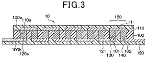
- the heat quantity control device has the following features. That is, the heat flux sensor has an insulation board (100) made of a thermoplastic resin.
- a plurality of first and second via holes (101, 102) is formed in the insulation board so that these via holes pass through a thickness direction of the insulation board.
- First layer connection members (130) and second layer connection members (140) are embedded in the first and second via holes, respectively.
- the first layer connection members and the second layer connection members are made of different metals.
- the first layer connection members and the second layer connection members have a structure in which the first layer connection members and the second layer connection members are alternately connected to each other in series.
- a front surface protection member (110) is formed on a surface (100a) of the insulation board, a front surface pattern (111) is formed on the front surface protection member (110), and a back surface protection member (120) is formed on a back surface (100b) of the insulation board, a back surface pattern (121) is formed on the back surface protection member (120), and the back surface protection member, the insulation board and the front surface protection member are assembled together.
- the first layer connection members and the second layer connection members generate an electromotive force due to a heat flux flowing between the first heating element and the second heating element.
- the control section controls a heat quantity generated in the first and second heating elements on the basis of the electromotive force generated in the heat flux sensors so that the heat flux flowing between the first heating element and the second heating element becomes not more than a predetermined value.
- the control section adjusts a heat quantity generated in at least one of the first and second heating elements so that a heat flux flowing between the first heating element and the second heating element becomes not more than the predetermined value, i.e. no difference in inside heat quantity (inside temperature) between the first heating element and the second heating element occurs.
- a heat flux flowing between the first heating element and the second heating element becomes not more than the predetermined value, i.e. no difference in inside heat quantity (inside temperature) between the first heating element and the second heating element occurs.
- the heat quantity control device further comprises, a second heat flux sensor (10b).
- the first heat flux sensor i.e., a first heat flux sensor (10a) is arranged between a first heating element and a second heating element formed adjacently to each other.
- the first heating element, the second heating element and a third heating element are stacked.
- the second heat flux sensor is arranged between the second heating element and the third heating element formed adjacently to each other.
- the control section is capable of controlling a heat quantity of the first heating element, the second heating element and the third heating element.
- the heat quantity control device has the following features.
- the first layer connection members and the second layer connection members which are alternately connected in the first heat flux sensor, generate an electromotive force due to a first heat flux between the first heating element and the second heating element.
- the first layer connection members and the second layer connection members which are alternately connected in the second heat flux sensor, generate an electromotive force due to a second heat flux flowing between the second heating element and the third heating element.
- the control section adjusts a heat quantity generated in at least one of the first heating element and the second heating element on the basis of the electromotive force generated in the first heat flux sensor so that the first heat flux becomes not less than the predetermined value. Further, the control section adjusts a heat quantity generated in at least one of the second heating element and the third heating element on the basis of the electromotive force generated in the second heat flux sensor so that the second heat flux becomes not less than the predetermined value.
- the heat quantity of the first heating element, the second heating element and the third heating element is adjusted so that the first heat flux flowing between the first heating element and the second heating element, and the second heat flux flowing between the second heating element and the third heating element become not more than the predetermined value, i.e. so that no difference occurs in inside heat quantity between the first heating element, the second heating element and the third heating element, it is possible to perform the equalization control of the inside heat quantity (inside temperature) generated in each of the first heating element, the second heating element and the third heating element with high accuracy.
- the heat quantity control device controls a heat quantity of a battery mounted on a motor vehicle. As shown in FIG. 1 , the heat quantity control device is equipped with the heat flux sensors 10 and the control section 20.
- the battery 1 supplies electric power to electric devices such as a vehicle motor.
- the battery 1 is composed of a lithium ion battery, a fuel cell, etc.
- the battery 1 has a structure in which a plurality of battery packs 1a, 1b and 1c are stacked.
- the first exemplary embodiment provides the battery 1 having a first battery pack 1a, a second battery pack 1b and a third battery pack 1c which are stacked.
- Each of the first battery pack 1a, the second battery pack 1b and the third battery pack 1c has a structure in which battery cells are stacked.
- Each of the first battery pack 1a, the second battery pack 1b and the third battery pack 1c is a heating element to generate heat energy when receiving electric power.
- each of the first battery pack 1a, the second battery pack 1b and the third battery pack 1c It is possible to control each of the first battery pack 1a, the second battery pack 1b and the third battery pack 1c to output its electric power, and adjust a heat quantity.
- No outside air is present between the battery packs adjacently to each other. That is, the battery packs are formed adjacently together, and the heat flux sensor 10 is formed between the battery packs.
- Discharging plates 2 and 3 are formed on the outside of the battery packs 1a, 1b and 1c in the battery 1.
- the two battery packs adjacent to each other in the battery packs 1a, 1b and 1c form the first heating element and the second heating element used in the claims.
- the first battery pack 1a, the second battery pack 1b and the third battery pack 1c form the first heating element, the second heating element and the third heating element.
- a temperature sensor 11 is arranged on a surface of the battery pack 1b at a central position between the battery packs 1a, 1b and 1c.
- the temperature sensor 11 outputs to the control section 2 a sensor signal which corresponds to a surface temperature of the battery pack 1b.
- the heat flux sensor 10 is arranged between the battery packs adjacently to each other. It is possible to transfer heat energy between the battery packs which are arranged adjacently to each other through the heat flux sensor 10.
- the heat flux sensor 10 detects a heat flux between the battery packs arranged adjacently to each other.
- the present exemplary embodiment uses the first heat flux sensor 10a and the second heat flux sensor 10b.
- the first heat flux sensor 10a is arranged between the first battery pack 1a and the second battery pack 1b.
- the second heat flux sensor 10b is arranged between the second battery pack 1b and the third battery pack 1c.
- the heat flux sensor 10, a front surface protection member 110 and a back surface protection member 120 are assembled together to form an assembly.
- the first layer connection members 130 and the second layer connection members 140 are alternately connected in series in this assembly.
- a description will now be given of a structure of the heat flux sensor 10.
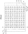
- the front surface protection member 110 is omitted from FIG. 2 for easy understanding.
- FIG. 2 is a view not showing a cross section, the first layer connection members 130 and the second layer connection members 140 are designated by hatching for easy understanding.
- the insulation board 100 has a rectangular shape and is made of thermoplastic resin such as polyether ether ketone (PEEK), poly ether imide (PEI), liquid crystal polymer (LCP), etc.
- the first via holes 101 and the second via holes 102 are alternately formed in a lattice pattern.
- the first via holes 101 and the second via holes 102 penetrate the insulation board 100 in a thickness direction thereof.
- each of the first via holes 101 and the second via holes 102 has a cylindrical shape having the same diameter, and penetrates the insulation board from the front surface 100a to the back surface 100b thereof. It is also acceptable for each via hole to have a taper shape or a square tube shape. When having a taper shape, a diameter of the via hole is reduced from the front surface 100a to the back surface 100b.
- the first layer connection member 130 is arranged in the first via hole 101 and the second layer connection member 140 is arranged in the second via hole 102. That is, the first layer connection members 130 and the second layer connection members 140 are alternately arranged in the insulation board 100.
- the first layer connection members and the second layer connection members 130 and 140 are made of different material to each other in order to cause the Seebeck effect.
- the first layer connection member 130 is made of a metal compound of a solid phase sintering in order to maintain a crystal structure, before performing sintering, of a plurality of metal atoms forming P-type Bi-Sb-Te alloy powder.
- the second layer connection member 140 is made of a metal compound of a solid phase sintering in order to maintain a crystal structure, before performing sintering, of a plurality of metal atoms forming N-type Bi-Te alloy powder.
- the front surface protection member 110 is formed on the front surface 100a of the insulation board 100.
- the front surface protection member 110 is made of a thermoplastic resin film having a rectangular plane shape such as polyether ether ketone (PEEK), poly ether imide (PEI), liquid crystal polymer (LCP), etc.
- the front surface protection member 110 has the same plane shape of the insulation board 10.
- a plurality of front surface patterns 111 is formed to separate from to each other on the surface 119a of the front surface protection member 110 which faces to the insulation board 100.
- the front surface patterns 111 are made of copper, etc. Each of the front surface patterns 111 is electrically connected to the first layer connection member 130 and the second layer connection member 140.
- the first layer connection member 130 and the second layer connection member 140 forming the pair are connected to the same front surface pattern 111. That is, the first layer connection member 130 and the second layer connection member 140 in each pair 150 are electrically connected to each other through the front surface patterns 111.
- the pair 150 is composed of one first layer connection member 130 and one second layer connection member 140 which are adjacently to each other along a longitudinal direction (along the left-right direction shown in FIG. 3 ) of the insulation board 100.
- the back surface protection member 120 is formed on the back surface 100b of the insulation board 100.
- the back surface protection member 120 is made of a thermoplastic resin film having a rectangular plane shape such as polyether ether ketone (PEEK), poly ether imide (PEI), liquid crystal polymer (LCP), etc.
- the back surface protection member 120 has a length which is longer than the length in the longitudinal direction of the insulation board 100.
- the back surface protection member 120 is formed on the back surface 100b of the insulation board 100 to project from both the end sections of the insulation board 100.
- a plurality of the back surface patterns 121 is formed to separate from to each other on the surface 120a of the back surface protection member 120 which faces to the insulation board 100.
- the back surface patterns 121 are made of copper, etc.
- Each of the back surface patterns 121 is electrically connected to the first layer connection member 130 and the second layer connection member 140.
- the first layer connection member 130 in one pair 150 and the second layer connection member 140 in the other pair are connected together through the same back surface pattern 121. That is, the first layer connection member 130 and the second layer connection member 140 belonging to the adjacent pairs are electrically connected through the same back surface pattern 121.
- first layer connection member 130 and the second layer connection member 140 which are adjacently to each other in a direction (vertical direction shown in FIG. 2 ) which is perpendicular to the longitudinal direction, are connected to each other through the same back surface pattern 121 at the outer edges of the insulation board 100.
- first layer connection member 130 and the second layer connection member 140 arranged adjacently to each other are connected to the same back surface pattern 121 so that these members 130 and 140 connected in series through the corresponding front surface pattern 111 and back surface pattern 121 are repeatedly formed in the longitudinal direction of the insulation board 100.
- the end part of the back surface patterns 121 connected in series through the patterns 111 and 121 is formed to be exposed outside from the insulation board 100.
- This exposed end part of the back surface patterns 121 acts as a terminal which is connected to the control section 20.
- the heat flux sensor 10 has the basic structure previously described.
- the heat flux sensors 10 outputs a sensor signal (electromotive force) to the control section 20.
- the sensor signal corresponds to a heat flux passing through the heat flux sensor 10 in the thickness direction thereof.
- the thickness direction of the heat flux sensor 10 is a laminating direction of the insulation board 100, the front surface protection member 110 and the back surface protection member 120.
- the front surface protection member 110 and the back surface protection member 120 with a high density by adjusting the number of the first via holes 101 and the second via holes 102, a diameter of each of the first via holes 101 and the second via holes 102, a gap between the first via holes 101 and the second via holes 102, etc.
- This makes it possible to increase the electromotive force generated in the heat flux sensor 10, and allows the heat flux sensor to have a multiple terminals, and a high sensitivity.
- the heat flux sensors 10 uses a metal compound (Bi-Sb-Te alloy, Bi-Te alloy) of a solid phase sintering in order to maintain a predetermined crystal structure as the first layer connection members 130 and the second layer connection members 140. That is, the first layer connection members 130 and the second layer connection members 140 are made of a sintered alloy while maintaining the crystal structure of a plurality of metal atoms.
- This structure makes it possible to increase an electromotive force as a voltage generated in the first layer connection members 130 and the second layer connection members 140 alternately connected in series. It is therefore possible for the heat flux sensor 10 to have a high sensitivity.
- the heat flux sensor 10 because the heat flux sensor 10 according to the present exemplary embodiment to have a structure in which the first via holes 101 and the second via holes 102 are formed in the insulation board 100 made of thermoplastic resin, it is possible to provide a thin heat flux sensor 10 having a large area. This makes it possible for the heat flux sensor 10 to detect a heat flux with high sensitivity without inhibiting heat transfer between the battery packs arranged adjacently to each other.
- the insulation board 100 is prepared.
- a plurality of the first via holes 101 is formed in the insulation board 100 by using a drill or laser, etc.
- each of the first via holes 101 is filled with a first conductive paste 131. It is preferable to use a method (or a device) of filling the first via holes 101 with the first conductive paste 131, as disclosed in the Japanese patent laid open publication No. 2010-50356 of the same applicant of the present invention.
- the insulation board 100 is arranged on a holder, which is not shown, through an absorption paper 160 so that the back surface 100b of the insulation board 100 faces the absorption paper 160.
- the first via holes 101 are filled with the first conductive paste 131 while the first conductive paste 131 is melted. This makes it possible for the absorption paper 160 to absorb a large part of organic solvent in the first conductive paste 131, and as a result, alloy powder is adhered in the first via holes 101.
- the absorption paper 160 capable of absorbing organic solvent contained in the first conductive paste 131. It is possible to use normal pure paper.
- a paste is used as the first conductive paste 131, which is produced by adding organic solvent such as paraffin having a melting point of 43 °C into Bi-Sb-Te alloy powder. A predetermined crystal structure of metal atoms is maintained in the Bi-Sb-Te alloy powder. Accordingly, the filling step of filling the first conductive paste 131 into the first via holes 101 is performed under a condition in which the surface 100a of the insulation board 100 is heated at a temperature of approximately 43 °C.
- a plurality of the second via holes 102 is formed in the insulation board 100 by using a drill or laser, etc. As previously described, the second via holes 102 and the first via holes 101 are alternately formed in the insulation board 100 to make a lattice pattern.
- each of the second via holes 102 is filled with a second conductive paste 141. It is possible to form the second via holes 102 by the same processes shown in FIG. 5 (b) .
- the insulation board 100 is arranged on the holder, which is not shown, through an absorption paper 160 so that the back surface 100b of the insulation board 100 faces to the absorption paper 160.
- the second via holes 102 are filled with the second conductive paste 141. This makes it possible for the absorption paper 160 to absorb a large part of organic solvent in the second conductive paste 141, and as a result, alloy powder is adhered in the second via holes 102.
- a paste is used as the second conductive paste 141, which is produced by adding organic solvent such as terpineol having a melting point at room temperature into Bi-Te alloy powder. A predetermined crystal structure of metal atoms is maintained in the Bi-Te alloy powder. That is, such organic solvent forming the second conductive paste 141 has the melting point which is lower than that of the organic solvent forming the first conductive paste 131.
- the step of filling the second via holes 102 with the second conductive paste 141 is performed under a condition in which the surface 100a of the insulation board 100 is maintained at room temperature.
- the filling process is performed to fill the second via holes 102 with the second conductive paste 141 under the condition in which the organic solvent contained in the first conductive paste 131 has been solidified. This makes it possible to suppress the second conductive paste 141 from entering into the first via holes 101.
- the organic solvent which is contained in the first conductive paste 131, but not absorbed by the absorption paper 160, is remained in the first via holes 101 as the solidified state.
- a copper foil, etc. is formed on the surface 110a, 120a of the front surface protection member 110 and the back surface protection member 120 which face the insulation board 100.
- the patterning of the copper foil is performed to form the front surface patterns 111 and the back surface patterns 121.
- the front surface patterns 111 are separated from each other.
- the back surface patterns 121 are separated from each other.
- the front surface patterns 111 and the back surface patterns 121 are prepared by the patterning of the copper foil.
- the back surface protection member 120, the insulation board 100 and the front surface protection member 110 are stacked in order to form a laminated body 170.
- the back surface protection member 120 is formed to have a longitudinal length which is longer than the longitudinal length of the insulation board 100 so that both the end sections of the back surface protection member 120 are projected from the insulation board 100.
- the laminated body 170 is disposed between a pair of pressing plates (not shown), as shown in FIG. 5 (h) . While heating and pressing the laminated body 170 disposed between the pressing plates in the vertical direction under vacuum in order to form the laminated body 170. Specifically, the first conductive paste 131 and the second conductive paste 141 are sintered and solidified to form the first layer connection members 130 and the second layer connection members 140 in the laminated body 170. Further, the laminated body 170 is formed while pressing and heating the first layer connection members 130 and the second layer connection members 140 so that the first layer connection members 130 and the second layer connection members 140 are connected to the front surface patterns 111 and the back surface patterns 121.
- the heat flux sensor 10 is produced by the manufacturing method previously described.
- the control section 20 is a heat quantity control means for controlling the heat quantity of each of the battery packs 1a, 1b and 1c.
- the control section 20 is comprised an electric control device having a microcomputer, a memory as a memory means, and a peripheral circuits thereof.
- the control section 20 adjusts the electric energy outputted from each of the battery packs 1a, 1b and 1c, and adjusts the heat quantity of each of the battery packs 1a, 1b and 1c.
- the control section 20 adjusts the heat quantity of the battery packs adjacently to each other so that a heat flux flowing between the battery packs adjacently to each other becomes zero (equalization control of inside heat quantity). It is sufficient to adjust the heat flux to a value which is not more than a predetermined value near zero.
- the control section 20 compares an electromotive voltage transmitted from the heat flux sensor 10 with a threshold value, and adjusts the heat quantity of each of the battery packs adjacently to each other so that the electromotive voltage becomes not more than the threshold value.
- the control section 20 performs the equalization control of the inside heat quantity (inside temperature) of the battery packs so that the battery 1 generates an electric power while suppressing the entire heat quantity of the battery 1 in order to have a minimum value, for example.
- the control section 20 reduces the heat quantity of the battery packs having a larger inside heat quantity in the battery packs 1a, 1b and 1c, and performs the equalization control of the inside heat quantity (inside temperature) of each of the battery packs 1a, 1b and 1c.
- control section 20 performs the equalization control of the inside heat quantity (inside temperature) during a warm-up operation mode when the battery packs operate under a low temperature condition.
- This warm-up operation mode is performed before the battery 1 supplies electric power to various electric devices in order for each of the battery packs 1a, 1b and 1c to have a temperature at which each of the battery packs 1a, 1b and 1c outputs electric power stably.
- the control section 20 performs the control process to increase a temperature of each of the battery packs 1a, 1b and 1c while adjusting the heat quantity of each of the battery packs 1a, 1b and 1c so that each of the battery packs 1a, 1b and 1c has the same inside heat quantity as each other.
- step S1 shown in FIG. 7 the control section 20 acquires a temperature T 1b of the battery pack 1b detected by the temperature sensor 11, a first electromotive voltage V 1a-1b detected by the first heat flux sensor 10a arranged between the battery pack 1a and the battery pack 1b, and a second electromotive voltage V 1b-1c detected by the second heat flux sensor 10b arranged between the battery packs 1b and the battery pack 1c.
- step S2 the control section 20 controls a heat quantity of the battery pack 1b on the basis of the temperature T 1b of the battery pack 1b obtained in step S1.
- step S3 the control section 20 controls the heat quantity of the battery pack 1a on the basis of the first electromotive voltage V 1a-1b obtained in step S1.
- step S4 the control section 20 controls the heat quantity of the battery pack 1c on the basis of the second electromotive voltage V 1b-1c obtained in step S1.
- the control section 20 judges whether or not the absolute value of a difference between the temperature T 1b of the battery pack obtained in step S1 and the target temperature becomes not more than a predetermined threshold value T th .
- the battery pack operates stable at the predetermined threshold value T th , for example, 300 °C.
- This predetermined threshold value T th is determined so that a difference between the temperature T 1b of the battery pack and the target temperature approaches zero.
- step S22 the control section 20 judges whether it is necessary to reduce or increase the heat quantity. That is, it is detected whether or not the predetermined threshold value T th obtained in step S1 is higher or not the target temperature (30 °C).
- the control section 20 calculates a decrement heat quantity which is necessary in step S23 to should be reduced.
- step S23 the control section 20 calculates the decrement heat quantity on the basis of the temperature T 1b obtained in step S1.
- the decrement heat quantity is calculated by multiplying a predetermined coefficient K 1 and a difference (T 1b - 30°C) between the temperature T 1b obtained in step S1 and the target temperature.
- the control section 20 outputs a control signal in step S24 so that the heat quantity of the battery pack 1b decreases by the decrement heat quantity calculated in step S23.
- the output of the battery pack 1b is adjusted on the basis of the decrement heat quantity.
- the control section 20 outputs a control signal to another control section capable of adjusting the output of the battery pack 1b. After this, the operation flow proceeds to step S3.
- step S22 when the judgment result in step S22 indicates negation (NO), because it is necessary to increase the heat quantity of the battery pack 1b, the control section 20 calculates an increment heat quantity which is necessary in step S25 for the battery pack 1b.
- step S25 the control section 20 calculates the increment heat quantity on the basis of the temperature T 1b obtained in step S1.
- the increment heat quantity is calculated by multiplying the predetermined coefficient K 1 and a difference (30°C - T 1b ) between the target temperature and the temperature T 1b obtained in step S1.
- the control section 20 outputs a control signal in step S24 so that the heat quantity of the battery pack 1b increases by the increment heat quantity calculated in step S25.
- the output of the battery pack 1b is adjusted on the basis of the increment heat quantity.
- the heat quantity of the battery pack 1b is increased by the processes in step S22, S25 and S24.
- the heat quantity of the battery pack 1b is decreased by the processes in step S22, S23 and S24.
- the output of the battery pack 1b is adjusted so that the heat quantity of the battery pack 1b increases and decreases until the temperature T 1b of the battery pack 1b approaches the target temperature.
- the output of the battery pack 1b is maintained to keep the heat quantity of the battery pack 1b.
- step S31 the control section 20 judges in step S31 whether or not the first electromotive voltage V 1a-1b obtained in step S1 is not more than a threshold voltage V th .
- the threshold voltage V th is determined so that the first electromotive voltage V 1a-1b is close to zero.
- step S32 the control section 20 judges whether it is necessary to reduce or increase the heat quantity. That is, it is detected whether or not the first electromotive voltage V 1a-1b obtained in step S1 is a positive value (V 1a-1b > 0). This means that the inside heat quantity of the battery pack 1a is less than the inside heat quantity of the battery pack 1b when the electromotive voltage value is a positive value under the structure in which the heat flux sensor 10a is arranged so that the electromotive voltage value corresponds to the heat flux flowing from the battery pack 1b to the battery pack 1a. Accordingly, when the judgment result in step S32 indicates affirmation (YES), because it is necessary to increase the heat quantity of the battery pack 1a, the control section 20 calculates an increment heat quantity which is necessary in step S33 to should be increased.
- step S33 the control section 20 calculates the increment heat quantity by multiplying the first electromotive voltage V 1a-1b obtained in step S1 and a predetermined coefficient K 2 together.
- the control section 20 outputs a control signal in step S34, like the step S24 so that the heat quantity of the battery pack 1a increases by the increment heat quantity calculated in step S33.
- the output of the battery pack 1a is adjusted on the basis of the increment heat quantity.
- step S32 when the judgment result in step S32 indicates negation (NO), because it is necessary to reduce the heat quantity of the battery pack 1a, the control section 20 calculates a decrement heat quantity which is necessary in step S35 for the battery pack 1a.
- step S35 for example, the control section 20 calculates the decrement heat quantity by multiplying the first electromotive voltage V 1a-1b and the predetermined coefficient K 2 together.
- the control section 20 outputs a control signal in step S34 so that the heat quantity of the battery pack 1a decreases by the decrement heat quantity calculated in step S35.
- the output of the battery pack 1a changes on the basis of the decrement heat quantity.
- step S32, S33 and S34 make it possible to increase the heat quantity of the battery pack 1a during a period in which the inside heat quantity of the battery pack 1a is less than the heat quantity of the battery pack 1b.
- the processes in step S32, S35 and S24 reduce the heat quantity of the battery pack 1a.
- the output of the battery pack 1a is adjusted so that the heat quantity of the battery pack 1a increases and decreases until the inside heat quantity of the battery pack 1a becomes equal to the heat quantity of the battery pack 1b.
- the output of the battery pack 1a is maintained so as to maintain the heat quantity of the battery pack 1a.
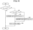
- step S41 the control section 20 judges in step S41 whether or not the second electromotive voltage V 1b-1c obtained in step S1 is not more than the threshold voltage V th .
- This threshold voltage V th is equal to the threshold value V th used in step S31.
- step S42 the control section 20 judges whether it is necessary to reduce or increase the heat quantity, that is, detects whether or not the second electromotive voltage V 1b-1c obtained in step S1 is a positive value (V 1b-1c > 0).
- V 1b-1c a positive value
- the inside heat quantity of the battery pack 1c is less than the inside heat quantity of the battery pack 1b when the electromotive voltage value is a positive value under the structure in which the heat flux sensor 10b is arranged so that the electromotive voltage value corresponding to the heat flux flowing from the battery pack 1b to the battery pack 1c.
- the control section 20 calculates an increment heat quantity which is necessary in step S43 to should be increased.
- step S43 the control section 20 calculates the increment heat quantity by multiplying the second electromotive voltage V 1b-1c obtained in step S1 and a predetermined coefficient K 3 together.
- the control section 20 outputs a control signal in step S34, like the step S24 so that the heat quantity of the battery pack 1c increases by the increment heat quantity calculated in step S43.
- the output of the battery pack 1a is changed on the basis of the increment heat quantity.
- the control flow shown in FIG. 7 is thereby completed. The operation flow returns to step S1.
- step S42 when the judgment result in step S42 indicates negation (NO), because it is necessary to reduce the heat quantity of the battery pack 1c, the control section 20 calculates a decrement heat quantity which is necessary in step S45 for the battery pack 1c.
- step S45 for example, the control section 20 calculates the decrement heat quantity by multiplying the second electromotive voltage V 1b-1c obtained in step S1 and the predetermined coefficient K 3 together.
- the control section 20 outputs a control signal in step S44 so that the heat quantity of the battery pack 1c decreases by the decrement heat quantity calculated in step S45.
- the output of the battery pack 1c changes on the basis of the decrement heat quantity.
- step S42, S43 and S44 make it possible to increase the heat quantity of the battery pack 1c during a period in which the inside heat quantity of the battery pack 1c is less than the heat quantity of the battery pack 1b.
- the processes in step S42, S45 and S44 reduce the heat quantity of the battery pack 1c.
- the output of the battery pack 1c is adjusted so that the heat quantity of the battery pack 1c increases and decreases until the inside heat quantity of the battery pack 1c becomes equal to the heat quantity of the battery pack 1b.
- the output of the battery pack 1c is maintained so as to maintain the heat quantity of the battery pack 1c.
- the heat quantity control device performs the equalization control of the inside heat quantity (inside temperature).
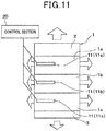
- the heat quantity control device has a structure shown in FIG. 11 and performs an equalization control of the inside heat quantity (inside temperature).
- the heat quantity control device as the comparative example is a usual heat quantity control device having a conventional structure explained in the section of [Problem to be solved by the Invention] previously described.
- a surface temperature of each of the battery packs 1a, 1b and 1c is detected by using each temperature sensor 11 (a first temperature sensor 11a, a second temperature sensor 11b and a third temperature sensor 11c), and the heat quantity of each of the battery packs 1a, 1b and 1c is adjusted so that the detection temperature becomes a target temperature.
- the first, second and third temperature sensors 11a, 11b and 11c are arranged on the surfaces of the battery packs 1a, 1b and 1c, respectively.
- the heat quantity control device can be considered for the heat quantity control device as the comparative example to control the heat quantity of each of the battery packs 1a, 1b and 1c so that the temperatures detected by the temperature sensors 11 become equal to each other in order to equalize the inside heat quantity (inside temperature) of each of the battery packs 1a, 1b and 1c, for example.
- a temperature of the surface of each of the battery packs 1a, 1b and 1c detected by each of the temperature sensor 11 is affected by an external ambient temperature in addition to the heat quantity of each of the battery packs 1a, 1b and 1c. That is, the surface temperature of the battery packs 1a and 1c arranged at the outer side of the battery is easily influenced by the external temperature.
- the surface temperature of the battery pack 1b sandwiched between the battery packs 1a and 1 becomes high because the battery pack 1b radiates a less amount of heat energy because the battery pack 1b is arranged inside.
- each of the battery packs 1a, 1b and 1c has the same inside heat quantity (inside temperature).
- the heat quantity control device can also be considered for the heat quantity control device as the comparative example to control the heat quantity of each of the battery packs 1a, 1b and 1c so that the detection temperature of each of the battery packs 1a, 1b and 1c becomes its target temperature on the basis of a difference in charging heat quantity between the battery packs 1a, 1b and 1c in order to equalize the inside heat quantity (inside temperature) of each of the battery packs 1a, 1b and 1c.
- the heat quantity control device as the comparative example to control the heat quantity of each of the battery packs 1a, 1b and 1c so that the detection temperature of each of the battery packs 1a, 1b and 1c becomes its target temperature on the basis of a difference in charging heat quantity between the battery packs 1a, 1b and 1c in order to equalize the inside heat quantity (inside temperature) of each of the battery packs 1a, 1b and 1c.
- the heat quantity control device adjusts the heat quantity of the battery packs which are arranged adjacently to each other so that the heat flux flowing between the adjacent battery packs becomes zero.
- This structure makes it possible to perform the equalization control of the inside heat quantity (inside temperature) of each of the battery packs 1a, 1b and 1c with a high accuracy because of adjusting the heat quantity of the battery packs arranged adjacently to each other to eliminate a difference in inside heat quantity (inside temperature) between the battery packs arranged adjacently to each other becomes zero.
- the heat quantity control device it is not necessary to adjust the heat quantity of each of the battery packs 1a, 1b and 1c even if an external temperature changes because the heat flux flowing between the battery packs arranged adjacently to each other after the inside heat quantity (inside temperature) of each of the battery packs 1a, 1b and 1c has been equal to each other.
- the abnormality monitoring device has the following features.
- the abnormality monitoring device is mounted to a surface of a heating element.
- the abnormality monitoring device has a heat flux sensor, a temperature sensor, and a judgment means.
- the heat flux sensor detects a heat flux flowing between the heating element and outside air.
- the temperature sensor detects a temperature of the outside air.
- the judgment detects whether or not an abnormality heating of the heating element occurs.
- a plurality of first and second via holes is formed in an insulation board so that the first and second via holes penetrate the insulation board in a thickness direction of the insulation board.
- a first layer connection member is embedded in each of the first via holes and a second layer connection member is embedded in each of the second via holes.
- the first layer connection members and the second layer connection members are alternately arranged and connected in series.
- the judgment means judges whether or not an abnormality heating state of the heating element occurs by comparing a detection result of the heat flux sensor with a judgment criteria. This judgment criteria is selected due to the temperature of the outside air from judgment criteria values. These judgment criteria values have been determined per temperature of the outside air when the heating element is working correctly.
- the abnormality monitoring device notifies occurrence of the abnormality heating state in the facility by a notification means when detecting the occurrence of the abnormality heating in the facility as the heating element. Further, the abnormality monitoring device performs the process of adjusting the heat quantity of the facility so that the heating state of the facility becomes normal.
- the abnormality monitoring device is equipped with the heat flux sensor 10 and the control section 20, like the structure of the heat quantity control device according to the first exemplary embodiment.
- the heat flux sensor 10 and the control section 20 in the abnormality monitoring device have the same structure of the heat flux sensor 10 and the control section 20 in the heat quantity control device according to the first exemplary embodiment.
- the heat flux sensor 10 in the abnormality monitoring device is mounted to a surface of the facility 30, which is different from the structure of the first exemplary embodiment, and outputs, to the control section 20, a sensor signal (electromotive voltage) due to the heat flux flowing between the facility 30 and the outside air.
- the abnormality monitoring device shown in FIG. 13 is arranged outside of the facility 30, and equipped with a temperature sensor 11, a buzzer (not shown) and display unit (not shown).
- the temperature sensor 11 outputs, to the control section 2, an output signal corresponding to a temperature of outside air.
- This buzzer and the display unit are notification means capable of notifying about the abnormality state when the abnormality heating occurs in the facility.
- the control section 20 is a judgment means capable of judging whether or not a heat flux flowing between the facility 30 and the outside air exceeds a predetermined value on the basis of a sensor signal transmitted from the heat flux sensor 10.
- the predetermined value has been determined to have an upper limit value of the heat flux when the facility 30 operates under a normal heating state.
- the control section 20 judges that the facility 30 operates under the normal heating state.
- the control section 20 judges that the facility 30 operates in the abnormality state.
- the control section 20 performs the judgment of detecting occurrence of the abnormality heating state in the facility 30.
- the control section 20 When judging the occurrence of the abnormality heating state of the facility 30, the control section 20 instructs the notification means such as the buzzer and the display unit to notify the occurrence of the abnormality heating state of the facility 30. Further, when the control section 20 has the ability to adjust the heat quantity of the facility 30, the control section 30 adjusts the heat quantity of the facility 30 on the basis of the sensor signal transmitted from the heat flux sensor 10 so that the heat flux flowing between the facility 30 and the outside air becomes not more than the predetermined value.
- control section 20 acquires an electromotive voltage (voltage value) of the heat flux sensor 10 and the temperature T of the outside air detected by the temperature sensor 11 in step S101.
- This threshold value V th is a judgment criteria which has been determined due to a heat flux detected when the facility 30 operates in the normal heating state. That is, the threshold value V th is a voltage value corresponding to the uppermost value of the heat flux when the facility 30 operates in the normal heating state. Because the heat flux detected when the facility 30 operates in the normal heating state is changed by the temperature of the outside air. Accordingly, when the facility 30 operates in the normal heating state, the relationship between the temperature of the outside air and the heat flux is detected in advance by experiments, etc. and the threshold value V th per temperature of the outside air is stored in advance in a memory section. The control section 20 selects the threshold value V th which corresponds to the temperature T of the outside air detected by the temperature sensor 11, and uses the selected threshold value V th in step S102.
- step S102 When the judgment result in step S102 indicates affirmation (YES) in step S102, the control section 20 judges in step S103 that the facility 30 operates in the normal heating state. The control flow shown in FIG. 14 is thereby completed.
- step S102 when the judgment result in step S102 indicates negation (NO) in step S102, the control section 20 judges in step S104 that the facility 30 operates in the abnormality heating state.
- the control section 20 outputs a control signal to the buzzer and the display unit in step S105 in order to notify the occurrence of the abnormality heating state. This makes it possible for the buzzer and the display unit to notify the occurrence of the abnormality if the facility 30. It is acceptable for the control section 20 to output a control signal to the facility 30 so as to reduce the heat quantity of the facility 30.
- the abnormality monitoring device detects the temperature of the heating element and judges the occurrence of the abnormality heating state of the facility 30 on the basis of the detected temperature of the heating element, because the temperature of the heating element varies due to the influence of the outside condition, there is a possible problem of it being difficult to detect occurrence of the abnormality heating state of the heating element with high accuracy. For example, when a temperature of the outside air (outside temperature) is low, because the outside air cools the heating element even if the heating element operates in the abnormality heating state, there is a possible case in which the detected temperature of the heating element becomes within the room temperature range.
- the abnormality monitoring device judges the occurrence of the abnormality heating state of the facility 30 on the basis of the detection result of the heat flux flowing between the facility 30 and the outside air by using the judgment criteria corresponding to the temperature of the outside air. Accordingly, when the facility 30 operates in the normal heating state, the judgment criteria is satisfied. On the other hand, when the facility 30 operates in the abnormality heating state, the judgment criteria is not satisfied. This makes it possible to judge whether the facility operates in the abnormality heating state or the normal heating state with high accuracy.
Landscapes
- Engineering & Computer Science (AREA)
- Chemical & Material Sciences (AREA)
- Manufacturing & Machinery (AREA)
- Chemical Kinetics & Catalysis (AREA)
- Electrochemistry (AREA)
- General Chemical & Material Sciences (AREA)
- Physics & Mathematics (AREA)
- General Physics & Mathematics (AREA)
- Combustion & Propulsion (AREA)
- Automation & Control Theory (AREA)
- Materials Engineering (AREA)
- Secondary Cells (AREA)
- Electromagnetism (AREA)
- Life Sciences & Earth Sciences (AREA)
- Sustainable Development (AREA)
- Sustainable Energy (AREA)
- Power Engineering (AREA)
- Resistance Heating (AREA)
- Investigating Or Analyzing Materials Using Thermal Means (AREA)
- Control Of Temperature (AREA)
- Battery Mounting, Suspending (AREA)
- Electric Propulsion And Braking For Vehicles (AREA)
- Surface Heating Bodies (AREA)
Applications Claiming Priority (3)
| Application Number | Priority Date | Filing Date | Title |
|---|---|---|---|
| JP2013117753 | 2013-06-04 | ||
| JP2013225558A JP5942960B2 (ja) | 2013-06-04 | 2013-10-30 | 発熱量制御装置 |
| PCT/JP2014/062004 WO2014196290A1 (ja) | 2013-06-04 | 2014-04-30 | 発熱量制御装置 |
Publications (3)
| Publication Number | Publication Date |
|---|---|
| EP3007027A1 EP3007027A1 (en) | 2016-04-13 |
| EP3007027A4 EP3007027A4 (en) | 2017-01-25 |
| EP3007027B1 true EP3007027B1 (en) | 2019-02-27 |
Family
ID=52007943
Family Applications (1)
| Application Number | Title | Priority Date | Filing Date |
|---|---|---|---|
| EP14807982.5A Not-in-force EP3007027B1 (en) | 2013-06-04 | 2014-04-30 | Heat quantity control device |
Country Status (7)
| Country | Link |
|---|---|
| US (1) | US9923250B2 (zh) |
| EP (1) | EP3007027B1 (zh) |
| JP (1) | JP5942960B2 (zh) |
| KR (1) | KR101824972B1 (zh) |
| CN (1) | CN105264454B (zh) |
| TW (1) | TWI521319B (zh) |
| WO (1) | WO2014196290A1 (zh) |
Families Citing this family (12)
| Publication number | Priority date | Publication date | Assignee | Title |
|---|---|---|---|---|
| JP6070506B2 (ja) | 2013-06-04 | 2017-02-01 | 株式会社デンソー | 生体検知器、車両用着座検知器およびシートベルト非着用警告システム |
| JP6481497B2 (ja) * | 2014-06-03 | 2019-03-13 | 株式会社デンソー | 温調制御装置 |
| JP6396812B2 (ja) * | 2015-01-20 | 2018-09-26 | 株式会社Soken | 充電率推定システム |
| JP6249009B2 (ja) * | 2015-11-12 | 2017-12-20 | 株式会社デンソー | 異常診断装置 |
| JP6358233B2 (ja) | 2015-11-12 | 2018-07-18 | 株式会社デンソー | 組付状態の診断装置 |
| JP6358234B2 (ja) * | 2015-11-12 | 2018-07-18 | 株式会社デンソー | 稼働状態の診断装置 |
| JP6256454B2 (ja) * | 2015-11-30 | 2018-01-10 | 株式会社デンソー | ヒータプレート、このヒータプレートを用いる熱流束センサの製造装置、このヒータプレートの製造方法、及び、このヒータプレートの製造装置 |
| CH711926A1 (de) * | 2015-12-17 | 2017-06-30 | Greenteg Ag | Messaufbau zur Funktionskontrolle von wiederaufladbaren Batterien. |
| US11036244B2 (en) | 2016-04-19 | 2021-06-15 | Gentherm Incorporated | Climate controlled seat with a thermal conditioning device which is controlled by determining a heat flux |
| CN108705943B (zh) * | 2018-05-22 | 2020-05-05 | 宁德时代新能源科技股份有限公司 | 一种电池组加热装置与控制方法 |
| JP2021015746A (ja) * | 2019-07-15 | 2021-02-12 | 株式会社デンソー | 電池温調装置 |
| CN114546004B (zh) * | 2022-04-25 | 2022-07-22 | 龙旗电子(惠州)有限公司 | 恒温箱温度调节方法、装置、设备、可读存储介质及产品 |
Family Cites Families (24)
| Publication number | Priority date | Publication date | Assignee | Title |
|---|---|---|---|---|
| FR2413646A1 (fr) * | 1978-01-02 | 1979-07-27 | Saint Gobain | Fluxmetre thermique |
| JPH0429021A (ja) | 1990-05-25 | 1992-01-31 | Hitachi Ltd | 温度計算法 |
| JP3680898B2 (ja) * | 1997-10-13 | 2005-08-10 | トヨタ自動車株式会社 | 二次電池の充放電制御装置 |
| JP3281873B2 (ja) | 1999-05-24 | 2002-05-13 | シャープ株式会社 | 温度制御装置 |
| JP2003194606A (ja) | 2001-12-21 | 2003-07-09 | Nippon Soken Inc | 熱式流量計 |
| JP4815733B2 (ja) * | 2003-03-24 | 2011-11-16 | 日産自動車株式会社 | 燃料電池システム |
| JP4366100B2 (ja) * | 2003-03-24 | 2009-11-18 | パナソニックEvエナジー株式会社 | 電池パック |
| JP4915049B2 (ja) * | 2004-08-05 | 2012-04-11 | 株式会社デンソー | 燃料電池システム |
| JP2006066299A (ja) | 2004-08-27 | 2006-03-09 | Toto Ltd | 人体加熱装置及び暖房便座装置 |
| KR100813247B1 (ko) * | 2006-10-17 | 2008-03-13 | 삼성에스디아이 주식회사 | 연료전지 시스템 및 그 운영방법 |
| US8574738B2 (en) * | 2007-03-14 | 2013-11-05 | Enerdel, Inc. | Battery pack assembly with integrated heater |
| CN100495280C (zh) * | 2007-11-01 | 2009-06-03 | 上海交通大学 | 动力锂电池组温度控制装置 |
| JP5368715B2 (ja) * | 2008-02-15 | 2013-12-18 | 江藤電気株式会社 | 熱流センサ |
| JP2010050356A (ja) | 2008-08-22 | 2010-03-04 | Shin-Etsu Chemical Co Ltd | ヘテロ接合太陽電池の製造方法及びヘテロ接合太陽電池 |
| JP5413241B2 (ja) * | 2010-02-25 | 2014-02-12 | いすゞ自動車株式会社 | 熱流束計の校正装置 |
| JP5875238B2 (ja) | 2011-03-16 | 2016-03-02 | 株式会社ダイヘン | 溶接装置 |
| CN102324590B (zh) * | 2011-04-29 | 2013-11-27 | 华南师范大学 | 锂离子动力电池组充放电过程中温度控制系统及方法 |
| JP2013019712A (ja) | 2011-07-08 | 2013-01-31 | Palmetrics Co Ltd | 比熱測定装置および比熱測定方法 |
| JP5726705B2 (ja) | 2011-10-13 | 2015-06-03 | 株式会社日本自動車部品総合研究所 | 組電池の昇温制御装置 |
| JP5376086B1 (ja) | 2012-05-30 | 2013-12-25 | 株式会社デンソー | 熱電変換装置の製造方法、熱電変換装置を備える電子部品の製造方法 |
| JP2014007376A (ja) | 2012-05-30 | 2014-01-16 | Denso Corp | 熱電変換装置 |
| JP5987811B2 (ja) * | 2013-06-04 | 2016-09-07 | 株式会社デンソー | 車両用の異常判定装置 |
| JP5999066B2 (ja) | 2013-06-04 | 2016-09-28 | 株式会社デンソー | 振動検出器 |
| JP6070506B2 (ja) | 2013-06-04 | 2017-02-01 | 株式会社デンソー | 生体検知器、車両用着座検知器およびシートベルト非着用警告システム |
-
2013
- 2013-10-30 JP JP2013225558A patent/JP5942960B2/ja not_active Expired - Fee Related
-
2014
- 2014-04-30 WO PCT/JP2014/062004 patent/WO2014196290A1/ja active Application Filing
- 2014-04-30 KR KR1020157034726A patent/KR101824972B1/ko active IP Right Grant
- 2014-04-30 CN CN201480032298.2A patent/CN105264454B/zh not_active Expired - Fee Related
- 2014-04-30 EP EP14807982.5A patent/EP3007027B1/en not_active Not-in-force
- 2014-04-30 US US14/895,840 patent/US9923250B2/en active Active
- 2014-05-07 TW TW103116239A patent/TWI521319B/zh not_active IP Right Cessation
Non-Patent Citations (1)
| Title |
|---|
| None * |
Also Published As
| Publication number | Publication date |
|---|---|
| JP5942960B2 (ja) | 2016-06-29 |
| TW201516605A (zh) | 2015-05-01 |
| JP2015015013A (ja) | 2015-01-22 |
| CN105264454A (zh) | 2016-01-20 |
| EP3007027A4 (en) | 2017-01-25 |
| US9923250B2 (en) | 2018-03-20 |
| TWI521319B (zh) | 2016-02-11 |
| KR101824972B1 (ko) | 2018-02-02 |
| CN105264454B (zh) | 2017-05-17 |
| EP3007027A1 (en) | 2016-04-13 |
| WO2014196290A1 (ja) | 2014-12-11 |
| KR20160008228A (ko) | 2016-01-21 |
| US20160141733A1 (en) | 2016-05-19 |
Similar Documents
| Publication | Publication Date | Title |
|---|---|---|
| EP3007027B1 (en) | Heat quantity control device | |
| JP6485206B2 (ja) | 熱流分布測定装置 | |
| US10113898B2 (en) | Liquid level detector for open vessel and closed vessel | |
| CN101911342B (zh) | 具有不对称端子的电池设计 | |
| CN112673515A (zh) | 感测式电池袋 | |
| US20140113166A1 (en) | Safety device for arrangement in a battery cell of a lithium-ion battery, lithium-ion battery cell with safety device | |
| JP2015015013A5 (zh) | ||
| JP5772518B2 (ja) | 電池短絡素子、電池短絡システム、および電池 | |
| JP6989030B2 (ja) | 外装体、異常検出器及び異常検出システム | |
| US10147976B2 (en) | Insulating container for battery, battery control device, and battery-failure detection method | |
| JP2019510351A (ja) | 内部温度の測定が可能な電池セル | |
| US20140004389A1 (en) | Exothermic component, electrode construction, electrical energy cell and cell assembly, as well as a manufacturing and actuation method | |
| EP2448038B1 (en) | Battery pack apparatus and method of storing a battery pack apparatus | |
| JP5092229B2 (ja) | 電池モジュール | |
| JP2007109536A (ja) | 温度検知装置 | |
| US20230155193A1 (en) | Secondary Battery And Detecting System | |
| US20230318069A1 (en) | All solid-state battery unit | |
| KR101416126B1 (ko) | 저온운용이 가능한 1차 배터리 팩 어셈블리 및 그 운용방법 | |
| CN106981680A (zh) | 用于测量电位差的导电测量层 |
Legal Events
| Date | Code | Title | Description |
|---|---|---|---|
| PUAI | Public reference made under article 153(3) epc to a published international application that has entered the european phase |
Free format text: ORIGINAL CODE: 0009012 |
|
| 17P | Request for examination filed |
Effective date: 20151210 |
|
| AK | Designated contracting states |
Kind code of ref document: A1 Designated state(s): AL AT BE BG CH CY CZ DE DK EE ES FI FR GB GR HR HU IE IS IT LI LT LU LV MC MK MT NL NO PL PT RO RS SE SI SK SM TR |
|
| AX | Request for extension of the european patent |
Extension state: BA ME |
|
| DAX | Request for extension of the european patent (deleted) | ||
| RIC1 | Information provided on ipc code assigned before grant |
Ipc: B60R 16/04 20060101ALI20161017BHEP Ipc: G05D 23/22 20060101AFI20161017BHEP |
|
| RIC1 | Information provided on ipc code assigned before grant |
Ipc: B60R 16/04 20060101ALI20161128BHEP Ipc: G05D 23/22 20060101AFI20161128BHEP |
|
| A4 | Supplementary search report drawn up and despatched |
Effective date: 20161223 |
|
| RIC1 | Information provided on ipc code assigned before grant |
Ipc: G05D 23/22 20060101AFI20161219BHEP Ipc: B60R 16/04 20060101ALI20161219BHEP |
|
| GRAP | Despatch of communication of intention to grant a patent |
Free format text: ORIGINAL CODE: EPIDOSNIGR1 |
|
| STAA | Information on the status of an ep patent application or granted ep patent |
Free format text: STATUS: GRANT OF PATENT IS INTENDED |
|
| INTG | Intention to grant announced |
Effective date: 20180904 |
|
| GRAS | Grant fee paid |
Free format text: ORIGINAL CODE: EPIDOSNIGR3 |
|
| GRAA | (expected) grant |
Free format text: ORIGINAL CODE: 0009210 |
|
| STAA | Information on the status of an ep patent application or granted ep patent |
Free format text: STATUS: THE PATENT HAS BEEN GRANTED |
|
| AK | Designated contracting states |
Kind code of ref document: B1 Designated state(s): AL AT BE BG CH CY CZ DE DK EE ES FI FR GB GR HR HU IE IS IT LI LT LU LV MC MK MT NL NO PL PT RO RS SE SI SK SM TR |
|
| REG | Reference to a national code |
Ref country code: GB Ref legal event code: FG4D |
|
| REG | Reference to a national code |
Ref country code: CH Ref legal event code: EP |
|
| REG | Reference to a national code |
Ref country code: DE Ref legal event code: R096 Ref document number: 602014041946 Country of ref document: DE |
|
| REG | Reference to a national code |
Ref country code: AT Ref legal event code: REF Ref document number: 1102291 Country of ref document: AT Kind code of ref document: T Effective date: 20190315 |
|
| REG | Reference to a national code |
Ref country code: IE Ref legal event code: FG4D |
|
| REG | Reference to a national code |
Ref country code: NL Ref legal event code: MP Effective date: 20190227 |
|
| REG | Reference to a national code |
Ref country code: LT Ref legal event code: MG4D |
|
| PG25 | Lapsed in a contracting state [announced via postgrant information from national office to epo] |
Ref country code: PT Free format text: LAPSE BECAUSE OF FAILURE TO SUBMIT A TRANSLATION OF THE DESCRIPTION OR TO PAY THE FEE WITHIN THE PRESCRIBED TIME-LIMIT Effective date: 20190627 Ref country code: LT Free format text: LAPSE BECAUSE OF FAILURE TO SUBMIT A TRANSLATION OF THE DESCRIPTION OR TO PAY THE FEE WITHIN THE PRESCRIBED TIME-LIMIT Effective date: 20190227 Ref country code: NL Free format text: LAPSE BECAUSE OF FAILURE TO SUBMIT A TRANSLATION OF THE DESCRIPTION OR TO PAY THE FEE WITHIN THE PRESCRIBED TIME-LIMIT Effective date: 20190227 Ref country code: NO Free format text: LAPSE BECAUSE OF FAILURE TO SUBMIT A TRANSLATION OF THE DESCRIPTION OR TO PAY THE FEE WITHIN THE PRESCRIBED TIME-LIMIT Effective date: 20190527 Ref country code: SE Free format text: LAPSE BECAUSE OF FAILURE TO SUBMIT A TRANSLATION OF THE DESCRIPTION OR TO PAY THE FEE WITHIN THE PRESCRIBED TIME-LIMIT Effective date: 20190227 Ref country code: FI Free format text: LAPSE BECAUSE OF FAILURE TO SUBMIT A TRANSLATION OF THE DESCRIPTION OR TO PAY THE FEE WITHIN THE PRESCRIBED TIME-LIMIT Effective date: 20190227 |
|
| PGFP | Annual fee paid to national office [announced via postgrant information from national office to epo] |
Ref country code: DE Payment date: 20190418 Year of fee payment: 6 |
|
| PG25 | Lapsed in a contracting state [announced via postgrant information from national office to epo] |
Ref country code: RS Free format text: LAPSE BECAUSE OF FAILURE TO SUBMIT A TRANSLATION OF THE DESCRIPTION OR TO PAY THE FEE WITHIN THE PRESCRIBED TIME-LIMIT Effective date: 20190227 Ref country code: BG Free format text: LAPSE BECAUSE OF FAILURE TO SUBMIT A TRANSLATION OF THE DESCRIPTION OR TO PAY THE FEE WITHIN THE PRESCRIBED TIME-LIMIT Effective date: 20190527 Ref country code: IS Free format text: LAPSE BECAUSE OF FAILURE TO SUBMIT A TRANSLATION OF THE DESCRIPTION OR TO PAY THE FEE WITHIN THE PRESCRIBED TIME-LIMIT Effective date: 20190627 Ref country code: LV Free format text: LAPSE BECAUSE OF FAILURE TO SUBMIT A TRANSLATION OF THE DESCRIPTION OR TO PAY THE FEE WITHIN THE PRESCRIBED TIME-LIMIT Effective date: 20190227 Ref country code: GR Free format text: LAPSE BECAUSE OF FAILURE TO SUBMIT A TRANSLATION OF THE DESCRIPTION OR TO PAY THE FEE WITHIN THE PRESCRIBED TIME-LIMIT Effective date: 20190528 Ref country code: HR Free format text: LAPSE BECAUSE OF FAILURE TO SUBMIT A TRANSLATION OF THE DESCRIPTION OR TO PAY THE FEE WITHIN THE PRESCRIBED TIME-LIMIT Effective date: 20190227 |
|
| PGFP | Annual fee paid to national office [announced via postgrant information from national office to epo] |
Ref country code: FR Payment date: 20190418 Year of fee payment: 6 |
|
| REG | Reference to a national code |
Ref country code: AT Ref legal event code: MK05 Ref document number: 1102291 Country of ref document: AT Kind code of ref document: T Effective date: 20190227 |
|
| PG25 | Lapsed in a contracting state [announced via postgrant information from national office to epo] |
Ref country code: EE Free format text: LAPSE BECAUSE OF FAILURE TO SUBMIT A TRANSLATION OF THE DESCRIPTION OR TO PAY THE FEE WITHIN THE PRESCRIBED TIME-LIMIT Effective date: 20190227 Ref country code: IT Free format text: LAPSE BECAUSE OF FAILURE TO SUBMIT A TRANSLATION OF THE DESCRIPTION OR TO PAY THE FEE WITHIN THE PRESCRIBED TIME-LIMIT Effective date: 20190227 Ref country code: DK Free format text: LAPSE BECAUSE OF FAILURE TO SUBMIT A TRANSLATION OF THE DESCRIPTION OR TO PAY THE FEE WITHIN THE PRESCRIBED TIME-LIMIT Effective date: 20190227 Ref country code: SK Free format text: LAPSE BECAUSE OF FAILURE TO SUBMIT A TRANSLATION OF THE DESCRIPTION OR TO PAY THE FEE WITHIN THE PRESCRIBED TIME-LIMIT Effective date: 20190227 Ref country code: AL Free format text: LAPSE BECAUSE OF FAILURE TO SUBMIT A TRANSLATION OF THE DESCRIPTION OR TO PAY THE FEE WITHIN THE PRESCRIBED TIME-LIMIT Effective date: 20190227 Ref country code: ES Free format text: LAPSE BECAUSE OF FAILURE TO SUBMIT A TRANSLATION OF THE DESCRIPTION OR TO PAY THE FEE WITHIN THE PRESCRIBED TIME-LIMIT Effective date: 20190227 Ref country code: CZ Free format text: LAPSE BECAUSE OF FAILURE TO SUBMIT A TRANSLATION OF THE DESCRIPTION OR TO PAY THE FEE WITHIN THE PRESCRIBED TIME-LIMIT Effective date: 20190227 Ref country code: RO Free format text: LAPSE BECAUSE OF FAILURE TO SUBMIT A TRANSLATION OF THE DESCRIPTION OR TO PAY THE FEE WITHIN THE PRESCRIBED TIME-LIMIT Effective date: 20190227 |
|
| REG | Reference to a national code |
Ref country code: DE Ref legal event code: R097 Ref document number: 602014041946 Country of ref document: DE |
|
| PG25 | Lapsed in a contracting state [announced via postgrant information from national office to epo] |
Ref country code: SM Free format text: LAPSE BECAUSE OF FAILURE TO SUBMIT A TRANSLATION OF THE DESCRIPTION OR TO PAY THE FEE WITHIN THE PRESCRIBED TIME-LIMIT Effective date: 20190227 Ref country code: PL Free format text: LAPSE BECAUSE OF FAILURE TO SUBMIT A TRANSLATION OF THE DESCRIPTION OR TO PAY THE FEE WITHIN THE PRESCRIBED TIME-LIMIT Effective date: 20190227 |
|
| REG | Reference to a national code |
Ref country code: CH Ref legal event code: PL |
|
| REG | Reference to a national code |
Ref country code: BE Ref legal event code: MM Effective date: 20190430 |
|
| PG25 | Lapsed in a contracting state [announced via postgrant information from national office to epo] |
Ref country code: AT Free format text: LAPSE BECAUSE OF FAILURE TO SUBMIT A TRANSLATION OF THE DESCRIPTION OR TO PAY THE FEE WITHIN THE PRESCRIBED TIME-LIMIT Effective date: 20190227 Ref country code: MC Free format text: LAPSE BECAUSE OF FAILURE TO SUBMIT A TRANSLATION OF THE DESCRIPTION OR TO PAY THE FEE WITHIN THE PRESCRIBED TIME-LIMIT Effective date: 20190227 Ref country code: LU Free format text: LAPSE BECAUSE OF NON-PAYMENT OF DUE FEES Effective date: 20190430 |
|
| PLBE | No opposition filed within time limit |
Free format text: ORIGINAL CODE: 0009261 |
|
| STAA | Information on the status of an ep patent application or granted ep patent |
Free format text: STATUS: NO OPPOSITION FILED WITHIN TIME LIMIT |
|
| GBPC | Gb: european patent ceased through non-payment of renewal fee |
Effective date: 20190527 |
|
| PG25 | Lapsed in a contracting state [announced via postgrant information from national office to epo] |
Ref country code: LI Free format text: LAPSE BECAUSE OF NON-PAYMENT OF DUE FEES Effective date: 20190430 Ref country code: CH Free format text: LAPSE BECAUSE OF NON-PAYMENT OF DUE FEES Effective date: 20190430 |
|
| 26N | No opposition filed |
Effective date: 20191128 |
|
| PG25 | Lapsed in a contracting state [announced via postgrant information from national office to epo] |
Ref country code: SI Free format text: LAPSE BECAUSE OF FAILURE TO SUBMIT A TRANSLATION OF THE DESCRIPTION OR TO PAY THE FEE WITHIN THE PRESCRIBED TIME-LIMIT Effective date: 20190227 Ref country code: BE Free format text: LAPSE BECAUSE OF NON-PAYMENT OF DUE FEES Effective date: 20190430 |
|
| PG25 | Lapsed in a contracting state [announced via postgrant information from national office to epo] |
Ref country code: TR Free format text: LAPSE BECAUSE OF FAILURE TO SUBMIT A TRANSLATION OF THE DESCRIPTION OR TO PAY THE FEE WITHIN THE PRESCRIBED TIME-LIMIT Effective date: 20190227 |
|
| PG25 | Lapsed in a contracting state [announced via postgrant information from national office to epo] |
Ref country code: IE Free format text: LAPSE BECAUSE OF NON-PAYMENT OF DUE FEES Effective date: 20190430 Ref country code: GB Free format text: LAPSE BECAUSE OF NON-PAYMENT OF DUE FEES Effective date: 20190527 |
|
| REG | Reference to a national code |
Ref country code: DE Ref legal event code: R119 Ref document number: 602014041946 Country of ref document: DE |
|
| PG25 | Lapsed in a contracting state [announced via postgrant information from national office to epo] |
Ref country code: FR Free format text: LAPSE BECAUSE OF NON-PAYMENT OF DUE FEES Effective date: 20200430 Ref country code: DE Free format text: LAPSE BECAUSE OF NON-PAYMENT OF DUE FEES Effective date: 20201103 |
|
| PG25 | Lapsed in a contracting state [announced via postgrant information from national office to epo] |
Ref country code: CY Free format text: LAPSE BECAUSE OF FAILURE TO SUBMIT A TRANSLATION OF THE DESCRIPTION OR TO PAY THE FEE WITHIN THE PRESCRIBED TIME-LIMIT Effective date: 20190227 |
|
| PG25 | Lapsed in a contracting state [announced via postgrant information from national office to epo] |
Ref country code: HU Free format text: LAPSE BECAUSE OF FAILURE TO SUBMIT A TRANSLATION OF THE DESCRIPTION OR TO PAY THE FEE WITHIN THE PRESCRIBED TIME-LIMIT; INVALID AB INITIO Effective date: 20140430 Ref country code: MT Free format text: LAPSE BECAUSE OF FAILURE TO SUBMIT A TRANSLATION OF THE DESCRIPTION OR TO PAY THE FEE WITHIN THE PRESCRIBED TIME-LIMIT Effective date: 20190227 |
|
| PG25 | Lapsed in a contracting state [announced via postgrant information from national office to epo] |
Ref country code: MK Free format text: LAPSE BECAUSE OF FAILURE TO SUBMIT A TRANSLATION OF THE DESCRIPTION OR TO PAY THE FEE WITHIN THE PRESCRIBED TIME-LIMIT Effective date: 20190227 |