EP3003822B1 - Volant de vehicule - Google Patents
Volant de vehicule Download PDFInfo
- Publication number
- EP3003822B1 EP3003822B1 EP14725451.0A EP14725451A EP3003822B1 EP 3003822 B1 EP3003822 B1 EP 3003822B1 EP 14725451 A EP14725451 A EP 14725451A EP 3003822 B1 EP3003822 B1 EP 3003822B1
- Authority
- EP
- European Patent Office
- Prior art keywords
- positioning means
- steering wheel
- rim
- previous
- hub
- Prior art date
- Legal status (The legal status is an assumption and is not a legal conclusion. Google has not performed a legal analysis and makes no representation as to the accuracy of the status listed.)
- Active
Links
Images

Classifications
-
- B—PERFORMING OPERATIONS; TRANSPORTING
- B60—VEHICLES IN GENERAL
- B60R—VEHICLES, VEHICLE FITTINGS, OR VEHICLE PARTS, NOT OTHERWISE PROVIDED FOR
- B60R16/00—Electric or fluid circuits specially adapted for vehicles and not otherwise provided for; Arrangement of elements of electric or fluid circuits specially adapted for vehicles and not otherwise provided for
- B60R16/02—Electric or fluid circuits specially adapted for vehicles and not otherwise provided for; Arrangement of elements of electric or fluid circuits specially adapted for vehicles and not otherwise provided for electric constitutive elements
- B60R16/023—Electric or fluid circuits specially adapted for vehicles and not otherwise provided for; Arrangement of elements of electric or fluid circuits specially adapted for vehicles and not otherwise provided for electric constitutive elements for transmission of signals between vehicle parts or subsystems
- B60R16/027—Electric or fluid circuits specially adapted for vehicles and not otherwise provided for; Arrangement of elements of electric or fluid circuits specially adapted for vehicles and not otherwise provided for electric constitutive elements for transmission of signals between vehicle parts or subsystems between relatively movable parts of the vehicle, e.g. between steering wheel and column
-
- B—PERFORMING OPERATIONS; TRANSPORTING
- B62—LAND VEHICLES FOR TRAVELLING OTHERWISE THAN ON RAILS
- B62D—MOTOR VEHICLES; TRAILERS
- B62D1/00—Steering controls, i.e. means for initiating a change of direction of the vehicle
- B62D1/02—Steering controls, i.e. means for initiating a change of direction of the vehicle vehicle-mounted
- B62D1/04—Hand wheels
-
- B—PERFORMING OPERATIONS; TRANSPORTING
- B62—LAND VEHICLES FOR TRAVELLING OTHERWISE THAN ON RAILS
- B62D—MOTOR VEHICLES; TRAILERS
- B62D1/00—Steering controls, i.e. means for initiating a change of direction of the vehicle
- B62D1/02—Steering controls, i.e. means for initiating a change of direction of the vehicle vehicle-mounted
- B62D1/04—Hand wheels
- B62D1/06—Rims, e.g. with heating means; Rim covers
Definitions
- the present invention generally relates to a steering wheel intended to be mounted on a motor vehicle, and in particular a steering wheel proposing a function requiring energy input at the rim.
- An object of the present invention is to meet the drawbacks mentioned above and in particular, first of all, to propose a flywheel having a simple metal structure between the hub and the rim, which however makes it possible to increase the possibilities of Passage of energy conductors between the hub and the rim without compromising the appearance quality of the steering wheel.
- said second injected polymer branch is arranged between the hub and the rim.
- the energy conductor supplies an engine, a heating system, a visual warning device, or a measurement and / or information capture on or by the driver.
- the positioning means comprise a first coupling portion arranged to couple the positioning means to the hub, and the positioning means comprise a second coupling portion arranged to couple the positioning means to the rim. , before the injection of the polymer.
- the positioning means being coupled to the hub on the one hand and the rim on the other hand, are perfectly positioned relative to these components before the injection of the polymer. It is conceivable to make the couplings by clipping.
- the rim is covered with a first foaming
- the second coupling portion is arranged to couple the positioning means to the first foaming of the rim.
- the positioning means comprise a first centralizer and a second centralizer arranged to cooperate with an injection mold, for locating the positioning means relative to the injection mold during the injection of the injected polymer.
- the location with respect to the injection mold guarantees a precise process, makes it possible to compensate for the dispersions of the components and to avoid designing the part that is rigid enough not to deform during the injection of the polymer.
- the first centralizer is arranged between a first and a second end of the positioning means, and is arranged to block at least three degrees of freedom in translation of the positioning means relative to the injection mold.
- the first centralizer arranged in the middle of the positioning means, is locked in translation relative to the injection mold, which prevents the positioning means from shifting in translation relative to the injection mold.
- the second centering device is arranged between the first centering device and the first end, and it is arranged to block at least one degree of freedom in translation of the positioning means with respect to the injection mold.
- the positioning means are locked in translation by the first centering device, and the locking according to a translation by the second centering device makes it possible to improve the accuracy of the location.
- the positioning means are a plastic support.
- the positioning means are a piece of thin thickness comprising notches with fins arranged to guide said at least one energy conductor.
- the energy conductor is positioned between the fins and the rest of the positioning means.
- said at least one energy conductor is an electrical conductor.
- said at least one energy conductor is a heat transfer fluid conductor.
- a second aspect of the invention is a motor vehicle comprising at least one steering wheel according to the first aspect of the invention.
- the figure 1 represents a vehicle steering wheel according to the invention.
- the steering wheel comprises four branches 10, 20, 30, 35 connecting a central hub 40 to a rim 50 which forms a gripping portion for a driver of the vehicle.
- the hub 40 comprises a metal portion 41 comprising a bore 42 to provide a mounting interface on a steering column not shown.
- the rim 50 comprises a metal core to provide good mechanical strength.
- This metal core is connected to the hub 40 by two mechanical connecting parts which are metal parts embedded in each of the branches 10 and 20, these branches may be called the first branches.
- the rim 50 is perfectly integral with the hub 40 and properly localized with respect to the latter, so that it is not necessary for the branches 30 and 35, which can be called the second branches, to comprise a mechanical connection piece. between the rim 50 and the hub 40, because the rigidity is sufficient.
- the mechanical connection pieces are overmolded during a polymer injection, to form the branches 10 and 20. It is possible to envisage using polyurethane as an injection polymer.
- the polyurethane in question here is what is commonly known as a lining foam, or injected polymer lining and serves to cover the frame of the steering wheel (the mechanical structural parts).
- the injected lining polymer is between the frame and the surface of the steering wheel (or can even form the outer surface).
- the second branches 30 and 35 are, on the other hand, made entirely of packing polymer and do not participate in the mechanical strength of the steering wheel. It is also conceivable to use expanded polypropylene as a packing.
- Each of the branches 10 and 20 further comprises control buttons 60 which serve as a man-machine interface for vehicle, such as a car radio or a geolocation system for example.
- These control buttons 60 are connected to the electrical network of the vehicle by electrical conductors that can be fully or partially embedded in the injected polymer forming the panels 10 and 20.
- the mechanical connecting parts connecting the rim 50 to the hub 40 serve as a support for positioning these electrical conductors, to ensure that they do not flush the surface of the branches 10 and 20, which would form an appearance defect driving the discarded flywheel.
- the dimensions and the number of these electrical conductors connecting the control buttons 60 to the electrical network of the vehicle make it difficult to implement additional energy conductors in the branches 10 and 20.
- the volume of the branches 10 and 20 should be increased. in order to pass more energy conductors, but due to aesthetic constraints, this increase in volume is not possible, and the number of energy conductors is therefore limited, because it must be possible to locate them in the injected polymer and the metal connecting pieces are then imperative.
- the invention proposes to pass such an additional conductor in one of the branches 30 or 35, without adding any mechanical connection piece between the rim 50 and the hub 40.
- the driver of energy between the rim 50 and the hub 40 is positioned in this branch 30 or 35 free of mechanical connection piece between the rim 50 and the hub 40 by positioning means, not visible on this figure 1 .
- the figure 2 represents the steering wheel of the figure 1 without the injected polymer, at the positioning means which will be embedded in the branch 30 after injection of the polymer.
- the positioning means consist of a plastic support 70 which provides a positioning of the energy conductor 80 which connects a vibrator 90 to the vehicle electrical network.
- the energy conductor 80 is correctly positioned relative to the hub 40 and the rim 50, so that during the injection operation of the polymer to form the branch 30, the energy conductor 80 is properly embedded in the injected polymer, and located at a predetermined distance from the surface of the branch 30, so as not to be flush with the surface or to cause a defect in the appearance of the branch 30.
- the energy conductor 80 is positioned by the support 70 by means of fins 73 which hold the energy conductor 80 in contact with the support 70, so as to guarantee the position of the assembly.
- the support 70 is coupled to the hub 40 by a first portion 71 which is a recess for cooperating with a protuberance of the hub 40.
- a second portion 72 of the support 70 allows coupling with the rim 50. It is possible to envisage a clipping of the second portion 72 in a cavity of the rim 50 for example.
- the support 70 is then secured to the hub 40 and the rim 50 to allow the injection operation in an injection mold.
- the support 70 During the injection operation in the injection mold, the support 70, already coupled to the hub 40 and the rim 50 is located relative to the injection mold, to ensure that the conductor 80 is properly embedded in the injected polymer.
- the support 70 comprises a first centralizer 74 and a second centralizer 75.
- the first centralizer 74 is arranged at a central position on the support 70 and cooperates with the injection mold for block at least three degrees of freedom in translation.
- the second centralizer 75 is in turn arranged near an upper end of the support 70 and cooperates with the injection mold to block at least one degree of freedom in translation. In this way, a correct positioning of the support 70 in the injection mold is obtained, while limiting the support deformations 70 that could cause blockages of the part in the mold.
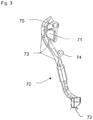
- the figure 3 represents the support 70 alone. It is therefore a piece of plastic material, with a thin thickness, and which has a hollow or concave cross section, in order to accommodate the energy conductor 80.
- the fins 73 can easily slide the driver of energy 80 between themselves and the rest of the body of the support 70. It is conceivable to realize the support 70 polyamide for example.
- the invention therefore makes it possible to offer the possibility of passing an energy conductor 80 in a flywheel leg 30 or 35, without the need for a metal connecting piece supporting between the hub 40 and the rim 50, to position the driver 80 energy, at lower cost, while ensuring a good quality of appearance.
Landscapes
- Engineering & Computer Science (AREA)
- Mechanical Engineering (AREA)
- Chemical & Material Sciences (AREA)
- Combustion & Propulsion (AREA)
- Transportation (AREA)
- Injection Moulding Of Plastics Or The Like (AREA)
- Steering Controls (AREA)
- Moulds For Moulding Plastics Or The Like (AREA)
Description
- La présente invention concerne de manière générale un volant destiné à être monté sur un véhicule automobile, et en particulier un volant proposant une fonction nécessitant un apport énergétique au niveau de la jante.
- Il est connu dans l'art antérieur des volants de véhicules avec un consommateur d'énergie dans sa jante, tel que celui décrit par le document
WO2010113551A1 . De plus, le documentUS 2013/055849 A1 divulgue un volant de véhicule selon le préambule de la revendication 1. En contrepartie, ce système présente notamment l'inconvénient de nécessiter un positionnement dans une branche du volant du conducteur d'énergie (ici un conducteur électrique) qui alimente le consommateur d'énergie, pour garantir que le conducteur n'affleurera pas la surface du polymère ultérieurement injecté autour de la structure métallique. Ce positionnement, réalisé par la partie métallique entre le moyeu et la jante, augmente le coût de la partie métallique d'une part, et limite le nombre de conducteurs pouvant passer du moyeu vers la jante, pour des raisons d'encombrement. - Un but de la présente invention est de répondre aux inconvénients mentionnés ci-dessus et en particulier, tout d'abord, de proposer un volant ayant une structure métallique simple entre le moyeu et la jante, et qui permet toutefois d'augmenter les possibilités de passage de conducteurs d'énergie entre le moyeu et la jante sans compromettre la qualité d'aspect du volant.
- Pour cela un premier aspect de l'invention concerne un volant de véhicule comprenant :
- un moyeu métallique,
- une jante,
- au moins une première branche comprenant une pièce de liaison mécanique solidarisant la jante au moyeu,
- Selon un mode de réalisation, ladite deuxième branche en polymère injecté est agencée entre le moyeu et la jante.
- Selon un mode de réalisation le conducteur d'énergie alimente un moteur, un système de chauffage, un avertisseur visuel, ou une mesure et/ou une saisie d'information sur ou par le conducteur.
- Selon un mode de réalisation, les moyens de positionnement comprennent une première portion d'accouplement agencée pour accoupler les moyens de positionnement au le moyeu, et les moyens de positionnement comprennent une deuxième portion d'accouplement agencée pour accoupler les moyens de positionnement à la jante, avant l'injection du polymère. Les moyens de positionnement, en étant accouplés sur le moyeu d'une part et la jante d'autre part, sont parfaitement positionnés par rapport à ces composants avant l'injection du polymère. On peut envisager de réaliser les accouplements par clipsage.
- Selon un mode de réalisation, la jante est recouverte d'un premier moussage, et la deuxième portion d'accouplement est agencée pour accoupler les moyens de positionnement au premier moussage de la jante. Cette mise en oeuvre permet d'utiliser une jante métallique standard, et de réaliser l'accouplement sur un modèle précis, sans surcoût car le moussage est spécifique à chaque modèle de volant.
- Selon un mode de réalisation, les moyens de positionnement comprennent un premier centreur et un deuxième centreur agencés pour coopérer avec un moule d'injection, pour localiser les moyens de positionnement par rapport au moule d'injection pendant l'injection du polymère injecté. La localisation par rapport au moule d'injection garantit un procédé précis, permet de compenser des dispersions des composants et d'éviter de concevoir la pièce suffisamment rigide pour ne pas se déformer lors de l'injection du polymère.
- Selon un mode de réalisation, le premier centreur est agencé entre une première et une deuxième extrémité des moyens de positionnement, et il est agencé pour bloquer au moins trois degré de liberté en translation des moyens de positionnement par rapport au moule d'injection. Le premier centreur, agencé au milieu des moyens de positionnement, est bloqué en translation par rapport au moule d'injection, ce qui empêche les moyens de positionnement de se décaler en translation par rapport au moule d'injection.
- Selon un mode de réalisation, le deuxième centreur est agencé entre le premier centreur et la première extrémité, et il est agencé pour bloquer au moins un degré de liberté en translation des moyens de positionnement par rapport au moule d'injection. Les moyens de positionnement sont bloqués en translation par le premier centreur, et le blocage selon une translation par le deuxième centreur permet d'améliorer la précision de la localisation.
- Selon un mode de réalisation, les moyens de positionnement sont un support en matière plastique.
- Selon un mode de réalisation, les moyens de positionnement sont une pièce d'épaisseur mince comprenant des encoches avec des ailettes agencées pour guider ledit au moins un conducteur d'énergie. Le conducteur d'énergie est positionné entre les ailettes et le reste des moyens de positionnement.
- Selon un mode de réalisation, ledit au moins un conducteur d'énergie est un conducteur électrique.
- Selon un mode de réalisation, ledit au moins un conducteur d'énergie est un conducteur de fluide caloporteur.
- Un second aspect de l'invention est un véhicule automobile comportant au moins un volant selon le premier aspect de l'invention.
- D'autres caractéristiques et avantages de la présente invention apparaîtront plus clairement à la lecture de la description détaillée qui suit d'un mode de réalisation de l'invention donné à titre d'exemple nullement limitatif et illustré par les dessins annexés, dans lesquels :
- la
figure 1 représente une vue de dessus d'un volant selon l'invention comprenant des moyens de positionnement dans une branche en polymère injecté ; - la
figure 2 représente une vue du volant au niveau des moyens de positionnement, avant injection du polymère ; - la
figure 3 représente une vue des moyens de positionnement. - La
figure 1 représente un volant de véhicule selon l'invention. Le volant comprend quatre branches 10, 20, 30, 35 reliant un moyeu 40 central à une jante 50 qui forme une partie de préhension pour un conducteur du véhicule. - Le moyeu 40 comprend une partie métallique 41 comprenant un alésage 42 pour assurer une interface de montage sur une colonne de direction non représentée.
- La jante 50 comprend une âme métallique pour lui procurer une bonne résistance mécanique. Cette âme métallique est reliée au moyeu 40 par deux pièces de liaison mécanique qui sont de pièces métalliques noyées dans chacune des branches 10 et 20, ces branches pouvant être appelées les premières branches. Ainsi, la jante 50 est parfaitement solidaire du moyeu 40 et correctement localisée par rapport à ce dernier, de sorte qu'il n'est pas nécessaire que les branches 30 et 35, pouvant être appelées les deuxièmes branches, comprennent de pièce de liaison mécanique entre la jante 50 et le moyeu 40, car la rigidité est suffisante. Les pièces de liaison mécanique sont surmoulées lors d'une injection de polymère, pour former les branches 10 et 20. On peut envisager d'utiliser du polyuréthane en tant que polymère d'injection. Le polyurethane ici en question est alors ce qu'il est commun d'appeler une mousse de garnissage, ou polymère injecté de garnissage et sert à recouvrir l'armature du volant (les pièces de structure mécanique). En d'autres termes, le polymère injecté de garnissage est entre l'armature et la surface du volant (ou peut même former la surface externe). Les deuxièmes branches 30 et 35 sont par contre intégralement réalisées en polymère de garnissage et ne participent pas à la résistance mécanique du volant. On peut envisager également d'utiliser du polypropylène expansé pour servir de garnissage.
- Chacune des branches 10 et 20 comprend en outre des boutons de commande 60 qui servent d'interface homme machine pour des appareils du véhicule, tels qu'un autoradio ou un système de géo localisation par exemple. Ces boutons de commande 60 sont reliés au réseau électrique du véhicule par des conducteurs électriques qui peuvent être tout ou partiellement noyés dans le polymère injecté formant les banches 10 et 20. A cet effet, les pièces de liaison mécanique reliant la jante 50 au moyeu 40 servent de support pour positionner ces conducteurs électriques, afin de garantir qu'ils n'affleureront pas la surface des branches 10 et 20, ce qui formerait un défaut d'aspect conduisant le volant au rebut. Les dimensions et le nombre de ces conducteurs électriques reliant les boutons de commande 60 au réseau électrique du véhicule font qu'il est difficile d'implanter des conducteurs d'énergie supplémentaires dans les branches 10 et 20.
- Cependant, il peut être nécessaire d'ajouter des appareils ou équipements à alimenter en énergie dans la jante 50, ce qui impose de pouvoir implanter un conducteur d'énergie dans une des branches 10 ou 20. On peut envisager par exemple d'implanter un moteur vibrant ou un système de climatisation dans la jante 50, et il faudra alimenter ces équipements en électricité ou en fluide caloporteur pour réaliser la fonction désirée. On peut en particulier envisager d'implanter un avertisseur visuel, ou une mesure et/ou une saisie d'information sur ou par le conducteur du véhicule.
- En tenant compte de la contrainte de localisation des conducteurs d'énergie dans les branches 10 ou 20 pour éviter des défauts d'aspect en raison de conducteurs d'énergie affleurant la surface du polymère injecté, il faudrait augmenter le volume des branches 10 et 20 pour pouvoir passer plus de conducteurs d'énergie, mais en raison des contraintes esthétiques, cette augmentation de volume n'est pas possible, et le nombre de conducteurs d'énergie est donc limité, car il faut pouvoir les localiser dans le polymère injecté et les pièces de liaison métalliques sont alors impératives.
- L'invention propose de faire passer un tel conducteur supplémentaire dans une des branches 30 ou 35, sans pour autant rajouter de pièce de liaison mécanique entre la jante 50 et le moyeu 40. A cet effet, le conducteur d'énergie entre la jante 50 et le moyeu 40 est positionné dans cette branche 30 ou 35 exempte de pièce de liaison mécanique entre la jante 50 et le moyeu 40 par des moyens de positionnement, non visibles sur cette
figure 1 . - La
figure 2 représente le volant de lafigure 1 sans le polymère injecté, au niveau des moyens de positionnement qui seront noyés dans la branche 30 après injection du polymère. Les moyens de positionnement sont constitués d'un support 70 en matière plastique qui offre un positionnement du conducteur d'énergie 80 qui relie un vibrateur 90 au réseau électrique du véhicule. Ainsi, le conducteur d'énergie 80 est correctement positionné par rapport au moyeu 40 et à la jante 50, de sorte que pendant l'opération d'injection du polymère pour former la branche 30, le conducteur d'énergie 80 soit correctement noyé dans le polymère injecté, et situé à une distance prédéterminée de la surface de la branche 30, pour ne pas affleurer la surface ni provoquer un défaut d'aspect de la branche 30. - Le conducteur d'énergie 80 est positionné par le support 70 grâce à des ailettes 73 qui maintiennent le conducteur d'énergie 80 au contact du support 70, de sorte à garantir la position de l'ensemble.
- Le support 70 est accouplé au moyeu 40 par une première portion 71 qui est un évidement destiné à coopérer avec une protubérance du moyeu 40. De plus, une deuxième portion 72 du support 70 permet de l'accoupler avec la jante 50. On peut envisager un clipsage de la deuxième portion 72 dans une cavité de la jante 50 par exemple. Le support 70 est alors solidarisé avec le moyeu 40 et la jante 50, pour permettre l'opération d'injection dans un moule d'injection.
- Lors de l'opération d'injection dans le moule d'injection, le support 70, déjà accouplé au moyeu 40 et à la jante 50 est localisé par rapport au moule d'injection, pour garantir que le conducteur 80 soit correctement noyé dans le polymère injecté. A cet effet, le support 70 comprend un premier centreur 74 et un deuxième centreur 75. Le premier centreur 74 est agencé à une position centrale sur le support 70 et coopère avec le moule d'injection pour bloquer au moins trois degré de liberté en translation. Le deuxième centreur 75 est quant à lui agencé à proximité d'une extrémité supérieure du support 70 et coopère avec le moule d'injection pour bloquer au moins un degré de liberté en translation. De cette sorte, un positionnement correct du support 70 dans le moule d'injection est obtenu, tout en limitant les déformations support 70 qui pourraient engendrer des blocages de la pièce dans le moule.
- La
figure 3 représente le support 70 seul. Il s'agit donc d'une pièce en matière plastique, avec une épaisseur mince, et qui présente une section transversale creuse ou concave, afin de pouvoir loger le conducteur d'énergie 80. Les ailettes 73 permettent de glisser aisément le conducteur d'énergie 80 entre elles-mêmes et le reste du corps du support 70. On peut envisager de réaliser le support 70 en polyamide par exemple. - L'invention permet donc d'offrir la possibilité de faire passer un conducteur d'énergie 80 dans une branche de volant 30 ou 35, sans nécessiter de pièce de liaison métallique faisant support entre le moyeu 40 et la jante 50, pour positionner le conducteur d'énergie 80, à moindre coût, tout en permettant de garantir une bonne qualité d'aspect.
- On peut donc prévoir de proposer ou non une option de chauffage de la jante ou de mise en vibration du volant sans modifier l'ensemble métallique de base moyeu 40 - jante 50 et pièce de liaison mécanique dans les branches 10 et 20.
- On comprendra que diverses modifications et/ou améliorations évidentes pour l'homme du métier peuvent être apportées aux différents modes de réalisation de l'invention décrits dans la présente description sans sortir du cadre de l'invention défini par les revendications annexées.
Claims (11)
- Volant de véhicule comprenant :- un moyeu (40) métallique,- une jante (50),- au moins une première branche (10, 20) comprenant une pièce de liaison mécanique solidarisant la jante (50) au moyeu (40),caractérisé en ce qu'il comprend au moins une deuxième branche (30, 35) en polymère injecté, exempte de pièce de liaison mécanique solidarisant la jante (50) au moyeu (40), et contenant au moins un conducteur d'énergie (80), le volant comprenant des moyens de positionnement agencés pour positionner ledit au moins un conducteur d'énergie (80) avant l'injection du polymère de ladite deuxième branche (30, 35) exempte de pièce de liaison mécanique, de sorte à garantir une distance prédéterminée entre ledit au moins un conducteur d'énergie (80) et une surface du polymère une fois injecté.
- Volant selon la revendication précédente, caractérisé en ce que les moyens de positionnement comprennent une première portion d'accouplement (71) agencée pour accoupler les moyens de positionnement au moyeu (40), et en ce que les moyens de positionnement comprennent une deuxième portion d'accouplement (72) agencée pour accoupler les moyens de positionnement à la jante (50), avant l'injection du polymère.
- Volant selon la revendication précédente, caractérisé en ce que la jante est recouverte d'un premier moussage, et en ce que la deuxième portion d'accouplement est agencée pour accoupler les moyens de positionnement au premier moussage de la jante (50).
- Volant selon l'une des revendications précédentes, caractérisé en ce que les moyens de positionnement comprennent un premier centreur (74) et un deuxième centreur (75) agencés pour coopérer avec un moule d'injection, pour localiser les moyens de positionnement par rapport au moule d'injection pendant l'injection du polymère injecté.
- Volant selon la revendication précédente, caractérisé en ce que le premier centreur (74) est agencé entre une première et une deuxième extrémité des moyens de positionnement, et en ce qu'il est agencé pour bloquer au moins trois degré de liberté en translation des moyens de positionnement par rapport au moule d'injection.
- Volant selon la revendication précédente, caractérisé en ce que le deuxième centreur (75) est agencé entre le premier centreur et la première extrémité, et en ce qu'il est agencé pour bloquer au moins un degré de liberté en translation des moyens de positionnement par rapport au moule d'injection.
- Volant selon l'une des revendications précédentes, caractérisé en ce que les moyens de positionnement sont un support (70) en matière plastique.
- Volant selon l'une des revendications précédentes, caractérisé en ce que les moyens de positionnement sont une pièce d'épaisseur mince comprenant des encoches avec des ailettes (73) agencées pour guider ledit au moins un conducteur d'énergie (80).
- Volant selon l'une des revendications précédentes, caractérisé en ce que ledit au moins un conducteur d'énergie (80) est un conducteur électrique.
- Volant selon l'une des revendications précédentes, caractérisé en ce que ledit au moins un conducteur d'énergie (80) est un conducteur de fluide caloporteur.
- Véhicule automobile comportant au moins un volant selon l'une des revendications précédentes.
Applications Claiming Priority (2)
| Application Number | Priority Date | Filing Date | Title |
|---|---|---|---|
| FR1301204A FR3005926B1 (fr) | 2013-05-27 | 2013-05-27 | Volant de vehicule |
| PCT/EP2014/060391 WO2014191266A1 (fr) | 2013-05-27 | 2014-05-21 | Volant de vehicule |
Publications (2)
| Publication Number | Publication Date |
|---|---|
| EP3003822A1 EP3003822A1 (fr) | 2016-04-13 |
| EP3003822B1 true EP3003822B1 (fr) | 2018-12-19 |
Family
ID=49209434
Family Applications (1)
| Application Number | Title | Priority Date | Filing Date |
|---|---|---|---|
| EP14725451.0A Active EP3003822B1 (fr) | 2013-05-27 | 2014-05-21 | Volant de vehicule |
Country Status (6)
| Country | Link |
|---|---|
| US (1) | US9988003B2 (fr) |
| EP (1) | EP3003822B1 (fr) |
| JP (1) | JP6230698B2 (fr) |
| CN (1) | CN105246761B (fr) |
| FR (1) | FR3005926B1 (fr) |
| WO (1) | WO2014191266A1 (fr) |
Families Citing this family (5)
| Publication number | Priority date | Publication date | Assignee | Title |
|---|---|---|---|---|
| FR3006976B1 (fr) | 2013-06-14 | 2016-02-26 | Autoliv Dev | Volant de vehicule |
| JP6164172B2 (ja) * | 2014-07-25 | 2017-07-19 | 豊田合成株式会社 | ステアリングホイール |
| FR3043381B1 (fr) | 2015-11-11 | 2018-04-27 | Autoliv Development Ab | Volant de vehicule |
| JP6437480B2 (ja) * | 2016-03-31 | 2018-12-12 | 本田技研工業株式会社 | ステアリング装置 |
| JP6300383B2 (ja) * | 2016-06-23 | 2018-03-28 | 本田技研工業株式会社 | 車両用ステアリングホイール |
Family Cites Families (35)
| Publication number | Priority date | Publication date | Assignee | Title |
|---|---|---|---|---|
| GB487012A (en) * | 1937-09-02 | 1938-06-14 | Thermo Plastics Inc | Automobile steering wheel construction |
| JPS6093564U (ja) * | 1983-12-02 | 1985-06-26 | 株式会社東海理化電機製作所 | 自動車用ステアリングホイ−ルの補強構造 |
| JPS6181270A (ja) * | 1984-09-27 | 1986-04-24 | Toyoda Gosei Co Ltd | ステアリングホイ−ル用ヒ−タ− |
| JPH06206548A (ja) * | 1993-01-13 | 1994-07-26 | Toho Rayon Co Ltd | 自動車用ステアリングホイール及びその製造方法 |
| CN1622893A (zh) * | 2002-06-28 | 2005-06-01 | W.E.T.汽车系统股份公司 | 带有电加热装置的方向盘 |
| GB2411942A (en) | 2004-03-10 | 2005-09-14 | Autoliv Dev | Steering wheel bearing housing with resilient bearing retainers |
| DE102004019066B3 (de) | 2004-04-20 | 2005-12-08 | Autoliv Development Ab | Steer-by-Wire-Lenkradeinheit mit integriertem Airbagmodul |
| CN2721487Y (zh) * | 2004-08-04 | 2005-08-31 | 比亚迪股份有限公司 | 一种防汗方向盘 |
| JP2006176037A (ja) * | 2004-12-24 | 2006-07-06 | Aisin Seiki Co Ltd | ハンドル冷却加熱装置 |
| DE102005061697B4 (de) | 2005-12-21 | 2008-08-28 | Autoliv Development Ab | Lenkrad |
| KR101354195B1 (ko) | 2006-09-04 | 2014-01-22 | 오토리브 디벨로프먼트 에이비 | 조향 휘일 장치 |
| JP2008120353A (ja) * | 2006-11-15 | 2008-05-29 | Aisin Seiki Co Ltd | ハンドル冷却加熱装置 |
| US20080134832A1 (en) | 2006-12-12 | 2008-06-12 | Autoliv Asp, Inc. | Steering wheel with reduced vibration transmission |
| DE202007013477U1 (de) * | 2007-09-25 | 2009-02-26 | Autoliv Development Ab | Fahrer-Alarmsystem für das Lenkrad eines Motorfahrzeugs |
| DE102008028126A1 (de) | 2008-06-13 | 2009-12-17 | Autoliv ASP, Inc., Ogden | Lenkradeinheit |
| DE102008062421A1 (de) | 2008-12-17 | 2010-07-08 | Autoliv Development Ab | Lenkradeinheit |
| JP5099042B2 (ja) * | 2009-02-24 | 2012-12-12 | 豊田合成株式会社 | ステアリングホイール |
| JP5415125B2 (ja) | 2009-04-02 | 2014-02-12 | タカタ株式会社 | ステアリングホイール、ステアリング装置 |
| JP4846818B2 (ja) * | 2009-04-03 | 2011-12-28 | 本田技研工業株式会社 | 車両用ステアリングホイールおよびその製造方法 |
| WO2010136197A1 (fr) | 2009-05-29 | 2010-12-02 | Autoliv Development Ab | Volant muni de contacts de klaxon fixés par liaison adhésive |
| EP2258603B1 (fr) | 2009-06-01 | 2012-10-10 | Autoliv Development AB | Améliorations de ou associées à un volant |
| GB0921658D0 (en) | 2009-12-10 | 2010-01-27 | Autoliv Dev | A steering wheel |
| US20120048056A1 (en) | 2010-08-31 | 2012-03-01 | Autoliv Asp, Inc. | Adaptive energy absorption steering wheel |
| EP2511154B1 (fr) | 2011-04-06 | 2013-05-29 | Autoliv Development AB | Volant de direction |
| EP2511153A1 (fr) | 2011-04-06 | 2012-10-17 | Autoliv Development AB | Volant de direction |
| US20130055849A1 (en) * | 2011-09-06 | 2013-03-07 | Sabic Innovative Plastics Ip B.V. | Steering apparatus thermal management |
| GB2508954B (en) * | 2012-09-26 | 2015-08-26 | Nihon Plast Co Ltd | Yieldable attachment of module to steering handle |
| FR3006976B1 (fr) * | 2013-06-14 | 2016-02-26 | Autoliv Dev | Volant de vehicule |
| JP6127201B2 (ja) * | 2014-02-21 | 2017-05-10 | 本田技研工業株式会社 | ステアリングホイール構造 |
| KR101907623B1 (ko) * | 2014-05-13 | 2018-12-10 | 젠썸 게엠베하 | 스티어링 장치용 온도 제어 장치 |
| JP6172081B2 (ja) * | 2014-07-25 | 2017-08-02 | 豊田合成株式会社 | ステアリングホイール |
| JP6164172B2 (ja) * | 2014-07-25 | 2017-07-19 | 豊田合成株式会社 | ステアリングホイール |
| JP6603845B2 (ja) * | 2014-10-03 | 2019-11-13 | アダマンド並木精密宝石株式会社 | ステアリングホイール用発電装置 |
| JP6371734B2 (ja) * | 2015-04-06 | 2018-08-08 | 株式会社東海理化電機製作所 | ステアリングホイール |
| JP6471054B2 (ja) * | 2015-06-25 | 2019-02-13 | 日本プラスト株式会社 | ステアリングホイール |
-
2013
- 2013-05-27 FR FR1301204A patent/FR3005926B1/fr not_active Expired - Fee Related
-
2014
- 2014-05-21 US US14/893,383 patent/US9988003B2/en active Active
- 2014-05-21 JP JP2016515728A patent/JP6230698B2/ja active Active
- 2014-05-21 EP EP14725451.0A patent/EP3003822B1/fr active Active
- 2014-05-21 CN CN201480030042.8A patent/CN105246761B/zh active Active
- 2014-05-21 WO PCT/EP2014/060391 patent/WO2014191266A1/fr not_active Ceased
Non-Patent Citations (1)
| Title |
|---|
| None * |
Also Published As
| Publication number | Publication date |
|---|---|
| CN105246761A (zh) | 2016-01-13 |
| FR3005926B1 (fr) | 2017-01-13 |
| JP2016524564A (ja) | 2016-08-18 |
| JP6230698B2 (ja) | 2017-11-15 |
| EP3003822A1 (fr) | 2016-04-13 |
| WO2014191266A1 (fr) | 2014-12-04 |
| US9988003B2 (en) | 2018-06-05 |
| US20160129860A1 (en) | 2016-05-12 |
| FR3005926A1 (fr) | 2014-11-28 |
| CN105246761B (zh) | 2017-03-22 |
Similar Documents
| Publication | Publication Date | Title |
|---|---|---|
| WO2014191266A1 (fr) | Volant de vehicule | |
| EP1431596B1 (fr) | Liaison autobloquante entre une tige à rotule et une partie plane | |
| EP2072342A1 (fr) | Peau de pare-chocs améliorée | |
| EP3114012B1 (fr) | Assemblage d'un cockpit et d'une structure de vehicule automobile et procede de montage correspondant | |
| EP2982576A1 (fr) | Pare-boue rotatif | |
| EP2898228B1 (fr) | Insert pour support de vehicule automobile, agencement mettant en oeuvre l'insert et vehicule automobile integrant l'agencement | |
| EP2550136B1 (fr) | Fixation d'un support d'équipement sur une peau en matière plastique d'une pièce de carrosserie de véhicule automobile | |
| JP6208075B2 (ja) | ステアリング | |
| FR3076243A1 (fr) | Procede de production d'une piece moulee en matiere plastique avec composants de support integre | |
| WO2011010051A1 (fr) | Ensemble de chauffage pour une vanne thermostatique et procédé de fabrication correspondant, ainsi que vanne thermostatique comportant un tel ensemble | |
| EP1712422B1 (fr) | Pièce de renfort d'un élément de carrosserie | |
| FR3025452A1 (fr) | ||
| EP2441648B1 (fr) | Carter de direction de véhicule automobile avec élément de renfort | |
| EP2062774A1 (fr) | Gaine de montage d'une tige de montage d'un appui tête comprenant une patte déformable | |
| WO2018178530A1 (fr) | Luge de preparation et procede d'assemblage pour un vehicule | |
| FR3056168A1 (fr) | Habillage interieur de vehicule a retour haptique | |
| EP2316628B1 (fr) | Pièce moulée comportant une paroi présentant un trou destiné a recevoir un pilote | |
| WO2017102564A1 (fr) | Allumeur pyrotechnique | |
| WO2015090987A1 (fr) | Traverse pour planche de bord avec support latéral a structure mixte métallo-plastique | |
| FR2956892A1 (fr) | Tuyau de raccordement d'une commande hydraulique | |
| FR3017834A1 (fr) | Dossier de siege apte a recevoir au moins un organe de guidage pour une tige d'appuie-tete. | |
| CN104564362A (zh) | 磁铁、齿轮及两者的连接结构和连接方法 | |
| FR2942607A1 (fr) | Dispositif d'absorption d'energie dispose entre la colonne de direction et le conducteur d'un vehicule automobile | |
| FR2710972A1 (fr) | Récipient collecteur en matière plastique pour échangeur de chaleur et son procédé de fabrication. | |
| FR3048476A1 (fr) | Dispositif de blocage d'un axe de commande d'une boite de vitesses automatique de vehicule |
Legal Events
| Date | Code | Title | Description |
|---|---|---|---|
| PUAI | Public reference made under article 153(3) epc to a published international application that has entered the european phase |
Free format text: ORIGINAL CODE: 0009012 |
|
| 17P | Request for examination filed |
Effective date: 20151116 |
|
| AK | Designated contracting states |
Kind code of ref document: A1 Designated state(s): AL AT BE BG CH CY CZ DE DK EE ES FI FR GB GR HR HU IE IS IT LI LT LU LV MC MK MT NL NO PL PT RO RS SE SI SK SM TR |
|
| AX | Request for extension of the european patent |
Extension state: BA ME |
|
| DAX | Request for extension of the european patent (deleted) | ||
| REG | Reference to a national code |
Ref country code: DE Ref legal event code: R079 Ref document number: 602014038178 Country of ref document: DE Free format text: PREVIOUS MAIN CLASS: B62D0001040000 Ipc: B62D0001060000 |
|
| GRAP | Despatch of communication of intention to grant a patent |
Free format text: ORIGINAL CODE: EPIDOSNIGR1 |
|
| STAA | Information on the status of an ep patent application or granted ep patent |
Free format text: STATUS: GRANT OF PATENT IS INTENDED |
|
| RIC1 | Information provided on ipc code assigned before grant |
Ipc: B60R 16/027 20060101ALI20180618BHEP Ipc: B62D 1/06 20060101AFI20180618BHEP Ipc: B62D 1/04 20060101ALI20180618BHEP |
|
| INTG | Intention to grant announced |
Effective date: 20180711 |
|
| GRAS | Grant fee paid |
Free format text: ORIGINAL CODE: EPIDOSNIGR3 |
|
| GRAA | (expected) grant |
Free format text: ORIGINAL CODE: 0009210 |
|
| STAA | Information on the status of an ep patent application or granted ep patent |
Free format text: STATUS: THE PATENT HAS BEEN GRANTED |
|
| AK | Designated contracting states |
Kind code of ref document: B1 Designated state(s): AL AT BE BG CH CY CZ DE DK EE ES FI FR GB GR HR HU IE IS IT LI LT LU LV MC MK MT NL NO PL PT RO RS SE SI SK SM TR |
|
| REG | Reference to a national code |
Ref country code: GB Ref legal event code: FG4D Free format text: NOT ENGLISH |
|
| REG | Reference to a national code |
Ref country code: CH Ref legal event code: EP |
|
| REG | Reference to a national code |
Ref country code: IE Ref legal event code: FG4D Free format text: LANGUAGE OF EP DOCUMENT: FRENCH |
|
| REG | Reference to a national code |
Ref country code: DE Ref legal event code: R096 Ref document number: 602014038178 Country of ref document: DE |
|
| REG | Reference to a national code |
Ref country code: AT Ref legal event code: REF Ref document number: 1078362 Country of ref document: AT Kind code of ref document: T Effective date: 20190115 |
|
| REG | Reference to a national code |
Ref country code: NL Ref legal event code: MP Effective date: 20181219 |
|
| PG25 | Lapsed in a contracting state [announced via postgrant information from national office to epo] |
Ref country code: LV Free format text: LAPSE BECAUSE OF FAILURE TO SUBMIT A TRANSLATION OF THE DESCRIPTION OR TO PAY THE FEE WITHIN THE PRESCRIBED TIME-LIMIT Effective date: 20181219 Ref country code: LT Free format text: LAPSE BECAUSE OF FAILURE TO SUBMIT A TRANSLATION OF THE DESCRIPTION OR TO PAY THE FEE WITHIN THE PRESCRIBED TIME-LIMIT Effective date: 20181219 Ref country code: BG Free format text: LAPSE BECAUSE OF FAILURE TO SUBMIT A TRANSLATION OF THE DESCRIPTION OR TO PAY THE FEE WITHIN THE PRESCRIBED TIME-LIMIT Effective date: 20190319 Ref country code: HR Free format text: LAPSE BECAUSE OF FAILURE TO SUBMIT A TRANSLATION OF THE DESCRIPTION OR TO PAY THE FEE WITHIN THE PRESCRIBED TIME-LIMIT Effective date: 20181219 Ref country code: FI Free format text: LAPSE BECAUSE OF FAILURE TO SUBMIT A TRANSLATION OF THE DESCRIPTION OR TO PAY THE FEE WITHIN THE PRESCRIBED TIME-LIMIT Effective date: 20181219 Ref country code: NO Free format text: LAPSE BECAUSE OF FAILURE TO SUBMIT A TRANSLATION OF THE DESCRIPTION OR TO PAY THE FEE WITHIN THE PRESCRIBED TIME-LIMIT Effective date: 20190319 |
|
| REG | Reference to a national code |
Ref country code: LT Ref legal event code: MG4D |
|
| REG | Reference to a national code |
Ref country code: AT Ref legal event code: MK05 Ref document number: 1078362 Country of ref document: AT Kind code of ref document: T Effective date: 20181219 |
|
| PG25 | Lapsed in a contracting state [announced via postgrant information from national office to epo] |
Ref country code: RS Free format text: LAPSE BECAUSE OF FAILURE TO SUBMIT A TRANSLATION OF THE DESCRIPTION OR TO PAY THE FEE WITHIN THE PRESCRIBED TIME-LIMIT Effective date: 20181219 Ref country code: AL Free format text: LAPSE BECAUSE OF FAILURE TO SUBMIT A TRANSLATION OF THE DESCRIPTION OR TO PAY THE FEE WITHIN THE PRESCRIBED TIME-LIMIT Effective date: 20181219 Ref country code: SE Free format text: LAPSE BECAUSE OF FAILURE TO SUBMIT A TRANSLATION OF THE DESCRIPTION OR TO PAY THE FEE WITHIN THE PRESCRIBED TIME-LIMIT Effective date: 20181219 |
|
| PG25 | Lapsed in a contracting state [announced via postgrant information from national office to epo] |
Ref country code: NL Free format text: LAPSE BECAUSE OF FAILURE TO SUBMIT A TRANSLATION OF THE DESCRIPTION OR TO PAY THE FEE WITHIN THE PRESCRIBED TIME-LIMIT Effective date: 20181219 |
|
| PG25 | Lapsed in a contracting state [announced via postgrant information from national office to epo] |
Ref country code: ES Free format text: LAPSE BECAUSE OF FAILURE TO SUBMIT A TRANSLATION OF THE DESCRIPTION OR TO PAY THE FEE WITHIN THE PRESCRIBED TIME-LIMIT Effective date: 20181219 Ref country code: PT Free format text: LAPSE BECAUSE OF FAILURE TO SUBMIT A TRANSLATION OF THE DESCRIPTION OR TO PAY THE FEE WITHIN THE PRESCRIBED TIME-LIMIT Effective date: 20190419 Ref country code: IT Free format text: LAPSE BECAUSE OF FAILURE TO SUBMIT A TRANSLATION OF THE DESCRIPTION OR TO PAY THE FEE WITHIN THE PRESCRIBED TIME-LIMIT Effective date: 20181219 Ref country code: CZ Free format text: LAPSE BECAUSE OF FAILURE TO SUBMIT A TRANSLATION OF THE DESCRIPTION OR TO PAY THE FEE WITHIN THE PRESCRIBED TIME-LIMIT Effective date: 20181219 Ref country code: PL Free format text: LAPSE BECAUSE OF FAILURE TO SUBMIT A TRANSLATION OF THE DESCRIPTION OR TO PAY THE FEE WITHIN THE PRESCRIBED TIME-LIMIT Effective date: 20181219 |
|
| PG25 | Lapsed in a contracting state [announced via postgrant information from national office to epo] |
Ref country code: RO Free format text: LAPSE BECAUSE OF FAILURE TO SUBMIT A TRANSLATION OF THE DESCRIPTION OR TO PAY THE FEE WITHIN THE PRESCRIBED TIME-LIMIT Effective date: 20181219 Ref country code: SK Free format text: LAPSE BECAUSE OF FAILURE TO SUBMIT A TRANSLATION OF THE DESCRIPTION OR TO PAY THE FEE WITHIN THE PRESCRIBED TIME-LIMIT Effective date: 20181219 Ref country code: IS Free format text: LAPSE BECAUSE OF FAILURE TO SUBMIT A TRANSLATION OF THE DESCRIPTION OR TO PAY THE FEE WITHIN THE PRESCRIBED TIME-LIMIT Effective date: 20190419 Ref country code: SM Free format text: LAPSE BECAUSE OF FAILURE TO SUBMIT A TRANSLATION OF THE DESCRIPTION OR TO PAY THE FEE WITHIN THE PRESCRIBED TIME-LIMIT Effective date: 20181219 Ref country code: EE Free format text: LAPSE BECAUSE OF FAILURE TO SUBMIT A TRANSLATION OF THE DESCRIPTION OR TO PAY THE FEE WITHIN THE PRESCRIBED TIME-LIMIT Effective date: 20181219 |
|
| REG | Reference to a national code |
Ref country code: DE Ref legal event code: R097 Ref document number: 602014038178 Country of ref document: DE |
|
| PLBE | No opposition filed within time limit |
Free format text: ORIGINAL CODE: 0009261 |
|
| STAA | Information on the status of an ep patent application or granted ep patent |
Free format text: STATUS: NO OPPOSITION FILED WITHIN TIME LIMIT |
|
| PG25 | Lapsed in a contracting state [announced via postgrant information from national office to epo] |
Ref country code: AT Free format text: LAPSE BECAUSE OF FAILURE TO SUBMIT A TRANSLATION OF THE DESCRIPTION OR TO PAY THE FEE WITHIN THE PRESCRIBED TIME-LIMIT Effective date: 20181219 Ref country code: DK Free format text: LAPSE BECAUSE OF FAILURE TO SUBMIT A TRANSLATION OF THE DESCRIPTION OR TO PAY THE FEE WITHIN THE PRESCRIBED TIME-LIMIT Effective date: 20181219 |
|
| 26N | No opposition filed |
Effective date: 20190920 |
|
| REG | Reference to a national code |
Ref country code: CH Ref legal event code: PL |
|
| GBPC | Gb: european patent ceased through non-payment of renewal fee |
Effective date: 20190521 |
|
| PG25 | Lapsed in a contracting state [announced via postgrant information from national office to epo] |
Ref country code: MC Free format text: LAPSE BECAUSE OF FAILURE TO SUBMIT A TRANSLATION OF THE DESCRIPTION OR TO PAY THE FEE WITHIN THE PRESCRIBED TIME-LIMIT Effective date: 20181219 Ref country code: CH Free format text: LAPSE BECAUSE OF NON-PAYMENT OF DUE FEES Effective date: 20190531 Ref country code: LI Free format text: LAPSE BECAUSE OF NON-PAYMENT OF DUE FEES Effective date: 20190531 |
|
| REG | Reference to a national code |
Ref country code: BE Ref legal event code: MM Effective date: 20190531 |
|
| PG25 | Lapsed in a contracting state [announced via postgrant information from national office to epo] |
Ref country code: LU Free format text: LAPSE BECAUSE OF NON-PAYMENT OF DUE FEES Effective date: 20190521 Ref country code: SI Free format text: LAPSE BECAUSE OF FAILURE TO SUBMIT A TRANSLATION OF THE DESCRIPTION OR TO PAY THE FEE WITHIN THE PRESCRIBED TIME-LIMIT Effective date: 20181219 |
|
| PG25 | Lapsed in a contracting state [announced via postgrant information from national office to epo] |
Ref country code: TR Free format text: LAPSE BECAUSE OF FAILURE TO SUBMIT A TRANSLATION OF THE DESCRIPTION OR TO PAY THE FEE WITHIN THE PRESCRIBED TIME-LIMIT Effective date: 20181219 |
|
| PG25 | Lapsed in a contracting state [announced via postgrant information from national office to epo] |
Ref country code: GB Free format text: LAPSE BECAUSE OF NON-PAYMENT OF DUE FEES Effective date: 20190521 Ref country code: IE Free format text: LAPSE BECAUSE OF NON-PAYMENT OF DUE FEES Effective date: 20190521 |
|
| PG25 | Lapsed in a contracting state [announced via postgrant information from national office to epo] |
Ref country code: BE Free format text: LAPSE BECAUSE OF NON-PAYMENT OF DUE FEES Effective date: 20190531 |
|
| PG25 | Lapsed in a contracting state [announced via postgrant information from national office to epo] |
Ref country code: CY Free format text: LAPSE BECAUSE OF FAILURE TO SUBMIT A TRANSLATION OF THE DESCRIPTION OR TO PAY THE FEE WITHIN THE PRESCRIBED TIME-LIMIT Effective date: 20181219 |
|
| PG25 | Lapsed in a contracting state [announced via postgrant information from national office to epo] |
Ref country code: GR Free format text: LAPSE BECAUSE OF FAILURE TO SUBMIT A TRANSLATION OF THE DESCRIPTION OR TO PAY THE FEE WITHIN THE PRESCRIBED TIME-LIMIT Effective date: 20181219 |
|
| PG25 | Lapsed in a contracting state [announced via postgrant information from national office to epo] |
Ref country code: HU Free format text: LAPSE BECAUSE OF FAILURE TO SUBMIT A TRANSLATION OF THE DESCRIPTION OR TO PAY THE FEE WITHIN THE PRESCRIBED TIME-LIMIT; INVALID AB INITIO Effective date: 20140521 Ref country code: MT Free format text: LAPSE BECAUSE OF FAILURE TO SUBMIT A TRANSLATION OF THE DESCRIPTION OR TO PAY THE FEE WITHIN THE PRESCRIBED TIME-LIMIT Effective date: 20181219 |
|
| PG25 | Lapsed in a contracting state [announced via postgrant information from national office to epo] |
Ref country code: MK Free format text: LAPSE BECAUSE OF FAILURE TO SUBMIT A TRANSLATION OF THE DESCRIPTION OR TO PAY THE FEE WITHIN THE PRESCRIBED TIME-LIMIT Effective date: 20181219 |
|
| P01 | Opt-out of the competence of the unified patent court (upc) registered |
Effective date: 20230507 |
|
| PGFP | Annual fee paid to national office [announced via postgrant information from national office to epo] |
Ref country code: DE Payment date: 20250528 Year of fee payment: 12 |
|
| PGFP | Annual fee paid to national office [announced via postgrant information from national office to epo] |
Ref country code: FR Payment date: 20250526 Year of fee payment: 12 |