EP3003676B1 - Verfahren zum hinterspritzen eines folienkörpers - Google Patents
Verfahren zum hinterspritzen eines folienkörpers Download PDFInfo
- Publication number
- EP3003676B1 EP3003676B1 EP14728143.0A EP14728143A EP3003676B1 EP 3003676 B1 EP3003676 B1 EP 3003676B1 EP 14728143 A EP14728143 A EP 14728143A EP 3003676 B1 EP3003676 B1 EP 3003676B1
- Authority
- EP
- European Patent Office
- Prior art keywords
- sacrificial
- layer electrode
- injection
- film
- tail
- Prior art date
- Legal status (The legal status is an assumption and is not a legal conclusion. Google has not performed a legal analysis and makes no representation as to the accuracy of the status listed.)
- Active
Links
Images






Classifications
-
- B—PERFORMING OPERATIONS; TRANSPORTING
- B29—WORKING OF PLASTICS; WORKING OF SUBSTANCES IN A PLASTIC STATE IN GENERAL
- B29C—SHAPING OR JOINING OF PLASTICS; SHAPING OF MATERIAL IN A PLASTIC STATE, NOT OTHERWISE PROVIDED FOR; AFTER-TREATMENT OF THE SHAPED PRODUCTS, e.g. REPAIRING
- B29C45/00—Injection moulding, i.e. forcing the required volume of moulding material through a nozzle into a closed mould; Apparatus therefor
- B29C45/14—Injection moulding, i.e. forcing the required volume of moulding material through a nozzle into a closed mould; Apparatus therefor incorporating preformed parts or layers, e.g. injection moulding around inserts or for coating articles
-
- B—PERFORMING OPERATIONS; TRANSPORTING
- B29—WORKING OF PLASTICS; WORKING OF SUBSTANCES IN A PLASTIC STATE IN GENERAL
- B29C—SHAPING OR JOINING OF PLASTICS; SHAPING OF MATERIAL IN A PLASTIC STATE, NOT OTHERWISE PROVIDED FOR; AFTER-TREATMENT OF THE SHAPED PRODUCTS, e.g. REPAIRING
- B29C45/00—Injection moulding, i.e. forcing the required volume of moulding material through a nozzle into a closed mould; Apparatus therefor
- B29C45/14—Injection moulding, i.e. forcing the required volume of moulding material through a nozzle into a closed mould; Apparatus therefor incorporating preformed parts or layers, e.g. injection moulding around inserts or for coating articles
- B29C45/14836—Preventing damage of inserts during injection, e.g. collapse of hollow inserts, breakage
-
- B—PERFORMING OPERATIONS; TRANSPORTING
- B29—WORKING OF PLASTICS; WORKING OF SUBSTANCES IN A PLASTIC STATE IN GENERAL
- B29C—SHAPING OR JOINING OF PLASTICS; SHAPING OF MATERIAL IN A PLASTIC STATE, NOT OTHERWISE PROVIDED FOR; AFTER-TREATMENT OF THE SHAPED PRODUCTS, e.g. REPAIRING
- B29C45/00—Injection moulding, i.e. forcing the required volume of moulding material through a nozzle into a closed mould; Apparatus therefor
- B29C45/14—Injection moulding, i.e. forcing the required volume of moulding material through a nozzle into a closed mould; Apparatus therefor incorporating preformed parts or layers, e.g. injection moulding around inserts or for coating articles
- B29C45/14065—Positioning or centering articles in the mould
- B29C45/14073—Positioning or centering articles in the mould using means being retractable during injection
-
- B—PERFORMING OPERATIONS; TRANSPORTING
- B29—WORKING OF PLASTICS; WORKING OF SUBSTANCES IN A PLASTIC STATE IN GENERAL
- B29C—SHAPING OR JOINING OF PLASTICS; SHAPING OF MATERIAL IN A PLASTIC STATE, NOT OTHERWISE PROVIDED FOR; AFTER-TREATMENT OF THE SHAPED PRODUCTS, e.g. REPAIRING
- B29C45/00—Injection moulding, i.e. forcing the required volume of moulding material through a nozzle into a closed mould; Apparatus therefor
- B29C45/14—Injection moulding, i.e. forcing the required volume of moulding material through a nozzle into a closed mould; Apparatus therefor incorporating preformed parts or layers, e.g. injection moulding around inserts or for coating articles
- B29C45/14754—Injection moulding, i.e. forcing the required volume of moulding material through a nozzle into a closed mould; Apparatus therefor incorporating preformed parts or layers, e.g. injection moulding around inserts or for coating articles being in movable or releasable engagement with the coating, e.g. bearing assemblies
-
- B—PERFORMING OPERATIONS; TRANSPORTING
- B29—WORKING OF PLASTICS; WORKING OF SUBSTANCES IN A PLASTIC STATE IN GENERAL
- B29C—SHAPING OR JOINING OF PLASTICS; SHAPING OF MATERIAL IN A PLASTIC STATE, NOT OTHERWISE PROVIDED FOR; AFTER-TREATMENT OF THE SHAPED PRODUCTS, e.g. REPAIRING
- B29C45/00—Injection moulding, i.e. forcing the required volume of moulding material through a nozzle into a closed mould; Apparatus therefor
- B29C45/14—Injection moulding, i.e. forcing the required volume of moulding material through a nozzle into a closed mould; Apparatus therefor incorporating preformed parts or layers, e.g. injection moulding around inserts or for coating articles
- B29C45/14827—Injection moulding, i.e. forcing the required volume of moulding material through a nozzle into a closed mould; Apparatus therefor incorporating preformed parts or layers, e.g. injection moulding around inserts or for coating articles using a transfer foil detachable from the insert
-
- B—PERFORMING OPERATIONS; TRANSPORTING
- B29—WORKING OF PLASTICS; WORKING OF SUBSTANCES IN A PLASTIC STATE IN GENERAL
- B29C—SHAPING OR JOINING OF PLASTICS; SHAPING OF MATERIAL IN A PLASTIC STATE, NOT OTHERWISE PROVIDED FOR; AFTER-TREATMENT OF THE SHAPED PRODUCTS, e.g. REPAIRING
- B29C45/00—Injection moulding, i.e. forcing the required volume of moulding material through a nozzle into a closed mould; Apparatus therefor
- B29C45/14—Injection moulding, i.e. forcing the required volume of moulding material through a nozzle into a closed mould; Apparatus therefor incorporating preformed parts or layers, e.g. injection moulding around inserts or for coating articles
- B29C45/14065—Positioning or centering articles in the mould
- B29C2045/14155—Positioning or centering articles in the mould using vacuum or suction
-
- B—PERFORMING OPERATIONS; TRANSPORTING
- B29—WORKING OF PLASTICS; WORKING OF SUBSTANCES IN A PLASTIC STATE IN GENERAL
- B29C—SHAPING OR JOINING OF PLASTICS; SHAPING OF MATERIAL IN A PLASTIC STATE, NOT OTHERWISE PROVIDED FOR; AFTER-TREATMENT OF THE SHAPED PRODUCTS, e.g. REPAIRING
- B29C45/00—Injection moulding, i.e. forcing the required volume of moulding material through a nozzle into a closed mould; Apparatus therefor
- B29C45/14—Injection moulding, i.e. forcing the required volume of moulding material through a nozzle into a closed mould; Apparatus therefor incorporating preformed parts or layers, e.g. injection moulding around inserts or for coating articles
- B29C45/14754—Injection moulding, i.e. forcing the required volume of moulding material through a nozzle into a closed mould; Apparatus therefor incorporating preformed parts or layers, e.g. injection moulding around inserts or for coating articles being in movable or releasable engagement with the coating, e.g. bearing assemblies
- B29C2045/1477—Removable inserts, e.g. the insert being peeled off after moulding
-
- B—PERFORMING OPERATIONS; TRANSPORTING
- B29—WORKING OF PLASTICS; WORKING OF SUBSTANCES IN A PLASTIC STATE IN GENERAL
- B29C—SHAPING OR JOINING OF PLASTICS; SHAPING OF MATERIAL IN A PLASTIC STATE, NOT OTHERWISE PROVIDED FOR; AFTER-TREATMENT OF THE SHAPED PRODUCTS, e.g. REPAIRING
- B29C45/00—Injection moulding, i.e. forcing the required volume of moulding material through a nozzle into a closed mould; Apparatus therefor
- B29C45/14—Injection moulding, i.e. forcing the required volume of moulding material through a nozzle into a closed mould; Apparatus therefor incorporating preformed parts or layers, e.g. injection moulding around inserts or for coating articles
- B29C45/14836—Preventing damage of inserts during injection, e.g. collapse of hollow inserts, breakage
- B29C2045/14844—Layers protecting the insert from injected material
-
- B—PERFORMING OPERATIONS; TRANSPORTING
- B29—WORKING OF PLASTICS; WORKING OF SUBSTANCES IN A PLASTIC STATE IN GENERAL
- B29K—INDEXING SCHEME ASSOCIATED WITH SUBCLASSES B29B, B29C OR B29D, RELATING TO MOULDING MATERIALS OR TO MATERIALS FOR MOULDS, REINFORCEMENTS, FILLERS OR PREFORMED PARTS, e.g. INSERTS
- B29K2101/00—Use of unspecified macromolecular compounds as moulding material
- B29K2101/12—Thermoplastic materials
-
- B—PERFORMING OPERATIONS; TRANSPORTING
- B29—WORKING OF PLASTICS; WORKING OF SUBSTANCES IN A PLASTIC STATE IN GENERAL
- B29K—INDEXING SCHEME ASSOCIATED WITH SUBCLASSES B29B, B29C OR B29D, RELATING TO MOULDING MATERIALS OR TO MATERIALS FOR MOULDS, REINFORCEMENTS, FILLERS OR PREFORMED PARTS, e.g. INSERTS
- B29K2623/00—Use of polyalkenes or derivatives thereof for preformed parts, e.g. for inserts
- B29K2623/04—Polymers of ethylene
- B29K2623/06—PE, i.e. polyethylene
-
- B—PERFORMING OPERATIONS; TRANSPORTING
- B29—WORKING OF PLASTICS; WORKING OF SUBSTANCES IN A PLASTIC STATE IN GENERAL
- B29K—INDEXING SCHEME ASSOCIATED WITH SUBCLASSES B29B, B29C OR B29D, RELATING TO MOULDING MATERIALS OR TO MATERIALS FOR MOULDS, REINFORCEMENTS, FILLERS OR PREFORMED PARTS, e.g. INSERTS
- B29K2627/00—Use of polyvinylhalogenides or derivatives thereof for preformed parts, e.g. for inserts
- B29K2627/06—PVC, i.e. polyvinylchloride
-
- B—PERFORMING OPERATIONS; TRANSPORTING
- B29—WORKING OF PLASTICS; WORKING OF SUBSTANCES IN A PLASTIC STATE IN GENERAL
- B29K—INDEXING SCHEME ASSOCIATED WITH SUBCLASSES B29B, B29C OR B29D, RELATING TO MOULDING MATERIALS OR TO MATERIALS FOR MOULDS, REINFORCEMENTS, FILLERS OR PREFORMED PARTS, e.g. INSERTS
- B29K2669/00—Use of PC, i.e. polycarbonates or derivatives thereof for preformed parts, e.g. for inserts
-
- B—PERFORMING OPERATIONS; TRANSPORTING
- B29—WORKING OF PLASTICS; WORKING OF SUBSTANCES IN A PLASTIC STATE IN GENERAL
- B29K—INDEXING SCHEME ASSOCIATED WITH SUBCLASSES B29B, B29C OR B29D, RELATING TO MOULDING MATERIALS OR TO MATERIALS FOR MOULDS, REINFORCEMENTS, FILLERS OR PREFORMED PARTS, e.g. INSERTS
- B29K2995/00—Properties of moulding materials, reinforcements, fillers, preformed parts or moulds
- B29K2995/0018—Properties of moulding materials, reinforcements, fillers, preformed parts or moulds having particular optical properties, e.g. fluorescent or phosphorescent
- B29K2995/0026—Transparent
-
- B—PERFORMING OPERATIONS; TRANSPORTING
- B29—WORKING OF PLASTICS; WORKING OF SUBSTANCES IN A PLASTIC STATE IN GENERAL
- B29L—INDEXING SCHEME ASSOCIATED WITH SUBCLASS B29C, RELATING TO PARTICULAR ARTICLES
- B29L2031/00—Other particular articles
- B29L2031/34—Electrical apparatus, e.g. sparking plugs or parts thereof
-
- B—PERFORMING OPERATIONS; TRANSPORTING
- B29—WORKING OF PLASTICS; WORKING OF SUBSTANCES IN A PLASTIC STATE IN GENERAL
- B29L—INDEXING SCHEME ASSOCIATED WITH SUBCLASS B29C, RELATING TO PARTICULAR ARTICLES
- B29L2031/00—Other particular articles
- B29L2031/34—Electrical apparatus, e.g. sparking plugs or parts thereof
- B29L2031/3475—Displays, monitors, TV-sets, computer screens
-
- H—ELECTRICITY
- H03—ELECTRONIC CIRCUITRY
- H03K—PULSE TECHNIQUE
- H03K17/00—Electronic switching or gating, i.e. not by contact-making and –breaking
- H03K17/94—Electronic switching or gating, i.e. not by contact-making and –breaking characterised by the way in which the control signals are generated
- H03K17/96—Touch switches
- H03K17/962—Capacitive touch switches
-
- H—ELECTRICITY
- H03—ELECTRONIC CIRCUITRY
- H03K—PULSE TECHNIQUE
- H03K17/00—Electronic switching or gating, i.e. not by contact-making and –breaking
- H03K17/94—Electronic switching or gating, i.e. not by contact-making and –breaking characterised by the way in which the control signals are generated
- H03K17/96—Touch switches
- H03K2017/9602—Touch switches characterised by the type or shape of the sensing electrodes
Definitions
- the invention relates to a film body, a method for injecting a film body and a Schuspritzwerkmaschine thereto.
- the invention relates to a method for the back-injection of layer electrodes for touch screens.
- Layer electrodes form the heart of a touchscreen.
- the individual sensor fields are contacted and the leads are brought together at the edge of the layer electrode, bundled and plugged for electrical connection to the touch module or the controller as a so-called Tail-in-example ZIF connector.
- the tail is part of the film that provides the layer electrode.
- the section of this film referred to as "tail" differs from the larger part of the layer electrode in that it has a different assignment with lines than the layer electrode, namely the bundled leads to the sensor electrode field contacts of the transparent layer electrode.
- the foil at the tail can, but does not have to be made transparent.
- these layered electrodes are laminated to touchscreens and the area comprising the tail is recessed from the bonding layer, which then does not firmly bond it to the housing, such as the "lens” or "cover”.
- Such layer electrode are for example from the US 2012267229 known.
- XP001573740 discloses a method of injecting a layer electrode.
- the tail can be protected by inserting a slider in front of the Schuspritzmaterial.
- the layer electrode which is placed by robots in the back injection tool in economically interesting processes, is positioned very accurately. But this is only costly feasible.
- Object of the present invention is therefore to provide a cost-effective way, so in the processing of the layer electrode by injection molding areas of the layer electrode, which should not be back-injected, such as the tail, remain free.
- areas not to be back-injected or left vacant are hereinafter referred to as "areas not to be back-injected or left vacant" and, for example, do not refer to the tail which is a part of the layer electrode but for the production of the touch screen as it is back-injected.
- the subject of the present invention is a film body for a layer electrode of a touch sensor comprising a free-to-use area and a sacrificial film, wherein the sacrificial film forms a composite with the layer electrode, in which the area to be left free of the sacrificial film is indeed completely covered but easily let go of this.
- the subject matter of the invention is a back-injection tool for the back-injection of a layer electrode, first vacuum lines for holding the layer electrode during the back-injection process and second vacuum lines for holding a sacrificial film during the back-injection process, wherein the first and second vacuum lines, in particular independently , are controllable.
- the injection takes place in such a way that as little as possible back-injection material passes between an area of the layer electrode which remains free to be left, in particular the tail and the sacrificial foil.
- the sacrificial foil has at least the dimensions of the region to be left free, that is, for example, of the tail.
- the sacrificial foil has at least the dimensions of the region of the layer electrode which is intended to remain free, in particular, for example, of the tail, preferably overhanging it This, so that a not exactly accurate placement does not cause that parts of the area but behind injected and glued.
- the sacrificial foil has a rectangular, for example, a square outline.
- the layer electrode preferably comprises a transparent plastic film, in particular one of a polyolefin such as polyethylene terephthalate (PET) or polycarbonate (PC) which is printed with conductive, non-transparent, for example metallic conductor tracks so that conductivity is ensured with simultaneous transparency of the film to the human eye ,
- a polyolefin such as polyethylene terephthalate (PET) or polycarbonate (PC)
- PET polyethylene terephthalate
- PC polycarbonate
- These conductive films are for example from the DE 10 2009 014 757.8 known.
- the sacrificial foil is laid loosely on the region of the layer electrode which is not to be back-injected, wherein means, in particular vacuum lines, are provided on the injection mold, fixing the layer electrode on the one hand and the sacrificial foil in the back injection mold on the other hand.
- the sacrificial film can be fixed by second vacuum lines.
- the two vacuum lines for example, can be controlled independently of each other and can be operated at the same or different pressure.
- the sacrificial foil before being introduced into the injection-molding tool onto the region of the free to be left Layer electrode, for example, the tail, applied and fixed with this in the Schuspritzwerkmaschine.
- the sacrificial film over its entire surface can be glued by its own adhesive force or by an adhesive additional layer with the freely remaining region of the layer electrode.
- the connection of the free region to the sacrificial foil is easily detachable, for example via vacuum lines, release adhesive, Longitudinal strip adhesive and / or adhesive adhesion takes place.
- the back-injected sacrificial foil of the free-to-stay area so for example the tail, without damaging it, for example, by cutting, again dissolved and / or deducted.
- the sacrificial foil remains as part of the Hinterspritz emotionss on this and is for example also a part of the layer electrode in the contact sensor after the formation of the layer electrode from the produced Deutschenspritzianu.
- the sacrificial foil covers the free region of the layer electrode before the closing of the injection-molding tool, for example the tail, over the entire surface and preferably flush. If the cover of the region to be left open is not completely sealed by the sacrificial film, then the injection direction is adjusted so that in all likelihood little or no back-injection material gets between the sacrificial film and the area to be left free.
- the back injection tool is closed, and the back injection process begins.
- the sacrificial foil has connected to the Schuspritzmaterial and the tail lies on the sacrificial foil and can be moved freely. It is possible that the sacrificial foil has become part of the Schuspritz stressess or can be deducted from this.
- the layer electrode is formed after the end of the injection from the Schuspritzelasticity, in particular cut out, for example with a laser beam.
- the sacrificial foil can be any type of foil which is, for example, of a polymer structure and consists of organic material.
- the sacrificial foil should not be with the material of the Tails, mainly metal or a metal alloy, chemically interacting. This also applies to all types of additives, both on the tail and on the sacrificial foil.
- the sacrificial film is particularly thin, for example, the film thickness is in the range of 1 to 250 microns, more preferably from 2 to 100 microns, and particularly preferably from 5 .mu.m to 75 .mu.m.
- the sacrificial foil and the carrier foil of the layer electrode have the same thickness. This results in an advantageous manner similar preferential characteristics of both films during the back injection process. As a result, for example, the choice of Schuspritz parameters can be facilitated.
- the transparent film referred to on which the conductive structures are printed to form the conductive functional film.
- the sacrificial foil is transparent.
- sacrificial foil is arbitrary, even a thin metal layer and / or a thin glass layer can be referred to here as sacrificial foil, because these materials behave in the thinnest form as foils.
- sacrificial foil is also a conventional type of foil used in technology, such as the conventional foil materials, PET, PC, polypropylene, polyaniline and / or polyimide.
- the sacrificial film is compatible with the carrier film of the layer electrode, so that after the back molding the sacrificial film from Schuspritzmaterial not even need to be separated.
- the sacrificial foil enhances the carrier foil of the layer electrode only at the point where the tail is formed.
- FIG. 1 shows a layer electrode 1 and a sacrificial foil 3, which are inserted in a Schuspritzwerkmaschine 2.
- the layer electrode 1 with the tail 7 is held over the vacuum line 8 formed in the rear injection mold 2, while the sacrificial film 3 is held over the second vacuum line 9 different therefrom.
- This is necessary since in this exemplary embodiment there is no coherent film body which comprises both the layer electrode 1 and the sacrificial film 3. Rather, here are the layer electrode 1 as the first film and the sacrificial layer 3 as independent, second film only loosely superposed, without connection to each other before.
- FIGS. 2a and 2 B is the sacrificial film 3 in conjunction with the layer electrode 1 before.
- FIG. 2a shows the top view of the film body of layer electrode 1, tail 7 and sacrificial film.
- FIG. 2b shows in cross section the position of the film body FIG. 2a in the back injection tool 2 before the back injection ( FIG. 2b above) and after the back injection ( FIG. 2b below).
- the embodiment according to FIG. 2a differs in the embodiment of FIG. 1 in that here the sacrificial foil 3 is connected to the layer electrode 1. Therefore, the second vacuum line 9 is omitted here for fixing the sacrificial foil 3 in the injection mold 2.
- the sacrificial foil 3 is held on the layer electrode 1 as part of the foil body of layer electrode 1, tail 7 and sacrificial foil 3 and with the layer electrode 1 and the tail 7 via the vacuum line 8 fixed in the rear injection mold 2.
- the sacrificial foil 3 is bonded to the layer electrode 1 via an additional layer, such as an adhesion layer (not shown).
- the sacrificial film 3 itself may be formed as an adhesion layer, so that no additional layer is required. It is particularly important that the film body is connected so that the tail 7 after injection ( FIG. 2b below) is detachable from the sacrificial foil 3. In the event that the sacrificial film 3 is formed as an adhesion layer, it is stable and insensitive to the conditions occurring during injection molding, such as high temperatures, etc.
- the back-injection material preferably passes through the opening 11 of the Schuspritztechnikmaschines 2, ie from above.
- the two side openings 4 and 6 and the lower opening. 5 are less preferred because backing material could creep under the sacrificial film 3.
- FIG. 2b Finally, it is shown how the injection molding in the rear injection mold 2 expires.
- the materials are chosen so that the tail 7 can be easily detached from the sacrificial foil 3. This may also be the case in the presence of a sacrificial foil 3 which is an adhesion foil.
- a sacrificial foil 3 made of a material such as Polyethylene (PE) and / or polyvinyl chloride (PVC), both characterized in that they have very smooth surfaces and then back-injected with a back-injection material such as polymethyl methacrylate (PMMA), polycarbonate (PC), acrylonitrile-butadiene-styrene (ABS).
- PE Polyethylene
- PVC polyvinyl chloride
- PMMA polymethyl methacrylate
- PC polycarbonate
- ABS acrylonitrile-butadiene-styrene
- the adhesion of the sacrificial foil 3 to the layer electrode 1 can in particular also be effected without adhesive alone by means of van der Waals interaction.
- FIG. 3 shows an alternative embodiment to the film body, the layer electrode 1, the tail 7 and the sacrificial film 3 comprising, of FIG. 2 ,
- FIG. 3 embodiment of the invention shown differs from the in FIG. 2a shown by the fact that here the sacrificial film 3 with the layer electrode 1 is not connected by an additional layer or by an adhesive property of the sacrificial film 3 itself, but by an adhesive strip 25, the sacrificial film 3 with the only in the connecting region of layer electrode 1 with 7 tail Layer electrode 1 connects.
- the adhesive strip 25 can also only partially along the connecting line 26 are located.
- the layer sequence of here in FIG. 3 Accordingly, the film body shown along the connecting line 26 can be described as follows, at the bottom of the layer electrode 1 with the tail 7, which are held in the injection mold 2 on the vacuum lines 8. The sacrificial foil 3 is loosely stacked on top of this, then the adhesive strip 25, which connects the sacrificial foil 3 to the layer electrode 1, is then located thereon.
- the injection direction 11 with respect to the injection directions 4, 5 and 6 is preferred because of these openings injected material could crawl under the sacrificial film 3 and then the free-to-stay area, in the example shown the tail 7, would be injected behind.
- FIGS. 4a . 4b and 4c show the sequence of an embodiment of the method according to the invention.
- the layer electrode 1 in the vicinity of the tails 7 has the contour curve 22.
- the contour curve 22 is consistent with that of the sacrificial film 3 and is shown in the illustration merely for the sake of simplicity offset drawn.
- the sacrificial foil 3 is according to FIG FIG. 2 glued to the tail 7, either by an additional layer, the two films glued together and / or in that the sacrificial film 3 itself has adhesive properties.
- the contours 22 in the embodiment correspond in reality with those of the sacrificial film 3, so that at the end of the layer electrode 1, where later the applied tail 7 is realized, a composite of the applied tail 7 of the layer electrode 1, the sacrificial film 3 and optionally an additional layer (not shown) is present.
- the outline of the tail 7, as it exists for example after the back molding and cutting, is structured in the embodiment shown here only after the back injection.
- contour curve 22 of the layer electrode 1 in the vicinity of the tails 7 forms a composite flush with the sacrificial foil 3 on three sides, backing material can not creep between the two foils and accordingly there is no preferred direction and / or preferential opening, from which the injection of the back-injection material he follows.
- the laser intensity can be selected, for example, such that the laser beam cuts through at least the layer electrode 1 of approximately 50 ⁇ m in thickness such that the contours of the tail 7 are formed.
- the sacrificial foil 3 can also be structured or cut.
- the injection tab 14 along the section line 13 can be separated with a laser beam adjusted accordingly. The laser structuring can be done in a single operation, each with different laser beam intensities for different sections 12 or 13 are used.
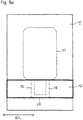
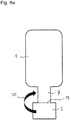
- FIGS. 5a and 5b show by way of example a method for producing the film body, for example according to FIG. 2 before being injected behind.
- FIG. 5a shows a section of an endless belt of a film 15, from which a layer electrode 1 according to the invention is preferably formed.
- These slides are from the DE 10 2009 014 575.8 known and preferably made of a polyolefin as a transparent support material with a pattern of conductive webs, wherein the dimensions of the webs and the pattern formed by them are selected so that the film Although conductive, but remains transparent to the human eye despite the non-transparent conductive paths.
- a thinner tape 16 is applied, from which the sacrificial films can be formed.
- this film composite of film 15 and tape 16 for example, miles long and wound up on a roll.
- the tape is structured and processed in the roll to roll process.
- a laser beam with a first intensity is applied along a cutting line 17 in order to cut through the film 15, for example with a film thickness in the range of 30 ⁇ m to 70 ⁇ m.
- layer electrodes 1 with Tails 7 can be cut out of the band.
- the band is severed with the material for the sacrificial film 3, for example with a film thickness in the range of 50 .mu.m to 100 .mu.m. Since in the region of the contours for the sacrificial foil 3, the band 16 and the band 15 must be severed, here is a correspondingly suitable laser beam, which can cut both films to choose.
- FIG. 2a After the procedure, a film body, as in FIG. 2a is shown to be produced. This one is in FIG. 5b shown again with layer electrode 1, tail 7 and sacrificial film. 3
- the film body can also be made from a tape, as in FIG. 6 shown.
- a film comprising layer electrode 1, tail 7 and sacrificial film 3 is cut out of a layer.
- This film has a predetermined bending point 19, along which the film is folded over in such a way that the sacrificial film 3, which initially adjoins the tail 7, lies on or below it.
- the film is bent along the line 19 and in direction 20.
- the Crease strip 21 cut off, for example by means of laser cutting, whereby the tail 7 is easily detached from the sacrificial foil 3.
- this embodiment is then preferably back-injected from the injection direction 5, since then the resulting Anspritzlasche (not shown) with the bending edge 21 can be separated together.
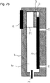
- FIGS. 7a and 7b show a Schuspritzwerkmaschine 2 with a tape fixation A, to which a protective tape 31 is attached, which takes over the function of the sacrificial film 3.
- the protective tape 31 is arranged so that it is still attached to the tape fixation A, but is so arched that it applies at the point of the tails 7 as sacrificial film 3 on this.
- the protective tape 31 is back-injected with the injection-molding process, it can subsequently be pushed upwards out of its position, thus exposing an injection-molded body 10 comprising a back-injected layer electrode 2 and an exposed tail 7.
- With 40 of the cavity in the injection mold 2 is designated, in which the Hinterspritz stresses 10 is formed.
- the protective tape 31 is pushed out of the back injection tool 2 after the back injection and, according to a preferred embodiment, is available for a further injection-molding operation.
- the protective tape 31 is advantageously equipped at least on one side with a non-stick coating.
- the protective tape 31 has the non-stick coating on the side facing the backmolding material, so that the backmolding material does not adhere to the protective tape 31 and can be pulled out without difficulty.
- the non-stick coating can be used up / worn down. It can therefore be provided that the protective tape 31 is arranged as an endless roll on the tape fixations A wound up. In each case after a few Schuspritzvor réellen the protective tape 31 can be rewound and there is fresh film material as a protective tape 31 is available.
- FIG. 7c shows a variation of this embodiment of the method with the protective tape 31:
- tabs 32 a to 32 c are formed, which serve as sacrificial films 3.
- the tab 32b is separated along the contour line 41.
- the separation is carried out for example by laser cutting, but can also by breaking a predetermined breaking point along the contour line 41, which is formed for example by a perforation provided there, are executed.
- the breaking of such a predetermined breaking point along the contour line 41 can be caused, for example, simply by further winding of the protective tape 31.
- FIG. 7c this embodiment is illustrated by the fact that prior to introduction into the injection tool 2, the protective tape 31 has coming from the right via a tab 32a, which has a predetermined breaking point (not shown).
- the protective tape is spooled to the left for injection, so that the tab 32b is then back-injected together with the film body of layer electrode 1 and 7 tail, covering the tail 7 as a flap 32 b.
- the protective tape 31 is wound on the endless rolls A 'to the belt fixation further to the left, wherein the predetermined breaking point breaks along the contour line 41 and thereby on the other side of the Hinterspritzwerkmaschinemaschines 2, the guard band 31 only one connection point 32c shows.
- tab 32 b The main part, referred to as tab 32 b, remains here after the back injection as a sacrificial foil 3 on the SchuspritzConsequently 10.
- For the subsequent Schuspritzvorgang is by rewinding by means of the endless rollers A 'a new tab 32a of the protective tape 31 ready.
Landscapes
- Engineering & Computer Science (AREA)
- Manufacturing & Machinery (AREA)
- Mechanical Engineering (AREA)
- Injection Moulding Of Plastics Or The Like (AREA)
Description
- Die Erfindung betrifft einen Folienkörper, ein Verfahren zum Hinterspritzen eines Folienkörpers und ein Hinterspritzwerkzeug dazu. Insbesondere betrifft die Erfindung ein Verfahren zum Hinterspritzen von Schichtelektroden für Berührungsbildschirme.
- Schichtelektroden bilden das Herzstück eines Berührungsbildschirms. In diesen Schichtelektroden werden die einzelnen Sensorfelder kontaktiert und die Zuleitungen am Rand der Schichtelektrode zusammengeführt, gebündelt und für die elektrische Anbindung an das Touchmodul oder den Controller als so genannter Tail in-beispielsweise- ZIF-Stecker gesteckt.
- Der Tail ist dabei Bestandteil der Folie, die die Schichtelektrode bereitstellt. Das als "Tail" bezeichnete Teilstück dieser Folie unterscheidet sich von dem größeren Teil der Schichtelektrode dadurch, dass es eine andere Belegung mit Leitungen als die Schichtelektrode aufweist, eben die gebündelten Zuleitungen zu den Sensor-Elektrodenfeld-Kontaktierungen der transparenten Schichtelektrode. Die Folie am Tail kann, muss aber nicht transparent ausgestaltet sein.
- Momentan ist die Entwicklung der Technologie so weit, dass bevorzugt flexible Schichtelektroden, die Trägerkörper wie Folien haben, bevorzugt eingesetzt werden. Derartige Schichtelektroden sind beispielsweise aus der
DE 10 2012 112 445.0 bekannt. - Üblicherweise werden diese Schichtelektroden zu Berührungsbildschirmen laminiert und der Bereich, welcher den Tail umfasst, wird von der verklebenden Schicht ausgespart, wodurch dann dieser nicht fest an das Gehäuse, beispielsweise die "Lens" oder den "Cover" gebunden wird.
- Derartige schichtelektrode sind beispielweise aus der
US 2012267229 bekannt. XP001573740 offenbart ein Verfahren zum Hinterspritzen einer Schichtelektrode. - Wirtschaftlich interessant ist die Aufgabe des Laminierens der Schichtelektroden zugunsten eines einfachen Hinterspritz-Prozesses.
- Beim Hinterspritzen der Schichtelektroden ist es wichtig, die Hinterspritzung der Zuleitungen, insbesondere des Tails zu vermeiden, damit dieser nicht mit verklebt wird.
- Bislang werden mehrere Möglichkeiten angedacht, den Tail vor dem Hinterspritzmaterial zu schützen. Beispielsweise kann der Tail durch Einbringen eines Schiebers vor dem Hinterspritzmaterial geschützt werden. Dazu ist erforderlich, dass die Schichtelektrode, die bei wirtschaftlich interessanten Prozessen durch Roboter im Hinterspritzwerkzeug platziert wird, ganz passgenau positioniert wird. Dies ist aber nur kostspielig realisierbar.
- Aufgabe der vorliegenden Erfindung ist es daher, eine kosteneffiziente Möglichkeit zu schaffen, damit bei der Verarbeitung der Schichtelektrode durch Hinterspritzen Bereiche der Schichtelektrode, die nicht hinterspritzt werden sollen, wie beispielsweise der Tail, frei bleiben.
- Diese Bereiche werden im Folgenden "nicht zu hinterspritzende oder frei zu bleibende Bereiche" genannt und bezeichnen beispielsweise den Tail, der ein Teil der Schichtelektrode ist, aber zur Herstellung des Berührungsbildschirms nicht wie diese hinterspritzt wird.
- Diese Aufgabe wird durch den Gegenstand der vorliegenden Anmeldung, wie in den Ansprüchen, der Beschreibung und den Figuren offenbart, gelöst.
- Allgemeine Erkenntnis der Erfindung ist es, eine Opferfolie beim Hinterspritzen auf einen Bereich der Schichtelektrode, beispielsweise den Tail, so anzubringen, dass dieser effektiv und kostengünstig vor dem Hinterspritzmaterial geschützt ist und der Tail nach dem Hinterspritzen problemlos von der Opferfolie wieder ablösbar ist. Dabei gibt es zwei Möglichkeiten: Zum Einen ist vorgesehen, dass die Opferfolie nach dem Hinterspritzen als Teil des Hinterspritzkörpers an diesem verbleibt. Zum Anderen ist es möglich, dass die Opferfolie nach erfolgtem Hinterspritzen auch vom Hinterspritzkörper wieder abgezogen wird. Die Opferfolie lässt sich auch als Abdeckfolie oder auch als Schutzfolie bezeichnen.
- Entsprechend ist Gegenstand der Erfindung ein Verfahren zum Hinterspritzen einer Schichtelektrode zum Herstellen eines Berührungssensors, wobei die Schichtelektrode zumindest einen nicht zu hinterspritzenden Bereich aufweist, folgende Verfahrensschritte umfassend:
- Abdecken des Bereichs der Schichtelektrode, der nicht zu hinterspritzen ist, mit einer Opferfolie,
- Einbringen der Schichtelektrode und der Opferfolie in ein Hinterspritzwerkzeug, Hinterspritzen der Schichtelektrode und der Opferfolie
- Bildung des Berührungssensors aus dem hergestellten Hinterspritzkörper.
- Ebenso ist Gegenstand der vorliegenden Erfindung ein Folienkörper für eine Schichtelektrode eines Berührungssensors, einen frei zu bleibenden Bereich und eine Opferfolie umfassend, wobei die Opferfolie mit der Schichtelektrode einen Verbund bildet, in dem der frei zu bleibenden Bereich von der Opferfolie zwar vollständig bedeckt ist, sich aber leicht von dieser ablösen lässt. Schließlich ist Gegenstand der Erfindung ein Hinterspritzwerkzeug für das Hinterspritzen einer Schichtelektrode, erste Vakuumlinien für die Halterung der Schichtelektrode während des Hinterspritzen-Vorgangs und zweite Vakuumlinien für die Halterung einer Opferfolie während des Hinterspritz-Vorgangs aufweisend, wobei die ersten und zweiten Vakuumlinien, insbesondere unabhängig voneinander, ansteuerbar sind.
- Nach einer bevorzugten Ausführungsform des Verfahrens erfolgt die Einspritzung so, dass möglichst wenig Hinterspritzmaterial zwischen einen frei zu bleibenden Bereich der Schichtelektrode, insbesondere den Tail und die Opferfolie gelangt.
- Dazu wird eine Öffnung des Hinterspritzwerkzeugs zum Einspritzen des Hinterspritzmaterials ausgesucht, durch die aufgrund ihrer Abmessungen, ihrer Kontur und/oder v.a. dem Ort ihrer Anordnung das Hinterspritzmaterial auf den Folienkörper an einer Stelle trifft, an der keine Lücke zwischen der Opferfolie und der Schichtelektrode vorhanden ist und/oder die Opferfolie mit der Schichtelektrode abdichtend verbunden ist.
- Nach einer bevorzugten Ausführungsform hat die Opferfolie zumindest die Ausmaße des frei zu bleibenden Bereichs, also beispielsweise des Tails.
- Die Opferfolie hat zumindest die Ausmaße des Bereichs der Schichtelektrode, der frei bleiben soll, insbesondere beispielsweise des Tails, bevorzugt überragt sie diesen, damit eine nicht ganz passgenaue Platzierung nicht dazu führt, dass Teile des Bereichs doch hinterspritzt und damit verklebt werden.
- Nach einer anderen bevorzugten Ausführungsform hat die Opferfolie einen rechteckigen, beispielsweise auch einen quadratischen Umriss.
- Die Schichtelektrode umfasst bevorzugt eine transparente Kunststofffolie, insbesondere eine aus einem Polyolefin wie Polyethylenterephtalat (PET) oder Polycarbonat (PC) die mit leitfähigen, nicht transparenten, beispielsweise metallischen Leiterbahnen so bedruckt ist, dass Leitfähigkeit gewährleistet ist bei gleichzeitiger Transparenz der Folie für das menschliche Auge. Diese leitfähigen Folien sind beispielsweise aus der
DE 10 2009 014 757.8 bekannt. - Nach einer Ausführungsform des Verfahrens wird die Opferfolie lose auf den Bereich der Schichtelektrode, der nicht hinterspritzt werden soll, gelegt, wobei am Hinterspritzwerkzeug Mittel, insbesondere Vakuumlinien vorgesehen sind, die zum einen die Schichtelektrode und zum anderen die Opferfolie in dem Hinterspritzwerkzeug fixieren.
- Beispielsweise kann nach erfolgter Fixierung der Schichtelektrode durch erste Vakuumlinien die Opferfolie durch zweite Vakuumlinien fixiert werden.
- Die beiden Vakuumlinien können beispielsweise unabhängig voneinander angesteuert werden und können bei gleichem oder verschiedenem Druck betrieben werden.
- Nach einer weiteren Ausführungsform der Erfindung wird die Opferfolie vor Einbringung in das Hinterspritzwerkzeug auf den frei zu bleibenden Bereich der Schichtelektrode, beispielsweise den Tail, aufgebracht und mit diesem in dem Hinterspritzwerkzeug fixiert.
- Dazu gibt es mehrere Techniken, die gemäß der Erfindung vorgeschlagen werden: Zum einen kann die Opferfolie ganzflächig durch eigene Adhäsionskraft oder durch eine adhäsive Zusatzschicht mit dem frei zu bleibenden Bereich der Schichtelektrode verklebt werden.
- Dann ist es möglich, die Opferfolie über einen Falz mit dem frei zu bleibenden Bereich gemeinsam herzustellen und bei gewünschter Abdeckung die Opferfolie einfach umzuknicken bzw. wegzuknicken, so dass der darunter liegende Bereich der Schichtelektrode bedeckt und damit vor der Hinterspritzung geschützt ist.
- Schließlich ist es möglich, die Opferfolie einfach über ein Klebeband auf der Schichtelektrode an der Stelle zu fixieren, wo sie abdecken soll.
- Bei all diesen Methoden liegt beim Einbringen der Schichtelektrode in das Hinterspritzwerkzeug nur ein Folienkörper vor, der im Hinterspritzwerkzeug fixiert werden muss. Deshalb reichen nach diesen Ausführungsformen auch herkömmliche Hinterspritzwerkzeuge mit nur einer Reihe Vakuumlinien aus.
- Egal wie die Opferfolie auf dem frei zu bleibenden Bereich der Schichtelektrode, insbesondere dem Tail, vor und während des Hinterspritzens gehalten wird, ist es wichtig, dass die Verbindung des frei zu bleibenden Bereichs zur Opferfolie leicht lösbar ist, also beispielsweise über Vakuumlinien, Releasekleber, Längsstreifenkleber und/oder Adhäsionskleber erfolgt. Nach dem Hinterspritzen wird die hinterspritzte Opferfolie von dem frei zu bleibenden Bereich, also beispielsweise dem Tail, ohne diesen zu beschädigen, beispielsweise auch durch Zerschneiden, wieder gelöst und/oder abgezogen.
- Nach einer bevorzugten Ausführungsform der Erfindung verbleibt die Opferfolie als Teil des Hinterspritzkörpers auf diesem und wird beispielsweise auch ein Teil der Schichtelektrode im Berührungssensor nach der Bildung der Schichtelektrode aus dem hergestellten Hinterspritzkörper.
- Die Opferfolie bedeckt vor dem Schließen des Hinterspritz-Werkzeugs den frei zu bleibenden Bereich der Schichtelektrode, also beispielsweise den Tail, ganzflächig und bevorzugt bündig abschließend. Wenn die Abdeckung des frei zu bleibenden Bereichs durch die Opferfolie nicht rundherum dicht ist, dann wird die Einspritzrichtung so angepasst, dass aller Wahrscheinlichkeit nach kein oder nur wenig Hinterspritzmaterial zwischen die Opferfolie und den frei zu bleibenden Bereich gelangt.
- Das Hinterspritzwerkzeug wird geschlossen, und der Hinterspritz-Vorgang beginnt. Nach beendeter Hinterspritzung hat sich die Opferfolie mit dem Hinterspritzmaterial verbunden und der Tail liegt auf der Opferfolie und kann frei bewegt werden. Dabei ist es möglich, dass die Opferfolie Teil des Hinterspritzkörpers geworden ist oder sich auch von diesem abziehen lässt.
- Die Schichtelektrode wird nach beendeter Hinterspritzung aus dem Hinterspritzkörper gebildet, insbesondere herausgeschnitten, beispielsweise mit Laserstrahl.
- Die Opferfolie kann jede Art von Folie sein, die beispielsweise polymer aufgebaut ist und aus organischem Material besteht. Die Opferfolie soll nicht mit dem Material des Tails, vornehmlich Metall oder eine Metalllegierung, chemisch wechselwirken. Dies gilt auch für alle Arten von Zusätzen, sowohl auf dem Tail als auch auf der Opferfolie.
- Nach einer vorteilhaften Ausführungsform ist die Opferfolie besonders dünn, beispielsweise liegt die Folienstärke im Bereich von 1 bis 250 µm insbesondere bevorzugt von 2 bis 100 µm und insbesondere bevorzugt von 5µm bis 75µm.
- Ganz besonders bevorzugt haben die Opferfolie und die Trägerfolie der Schichtelektrode die gleiche Dicke. Hierdurch ergeben sich in vorteilhafter Weise gleichartige Vorzugscharakteristiken an beiden Folien während des Hinterspritzvorgangs. Dadurch kann beispielsweise die Wahl der Hinterspritz-Parameter erleichtert werden.
- Als Trägerfolie der Schichtelektrode wird gemäß der
DE 10 2012 112 445.0 hier die transparente Folie bezeichnet, auf der die leitfähigen Strukturen zur Bildung der leitfähigen Funktionsfolie aufgedruckt sind. - Nach einer weiteren Ausführungsform ist die Opferfolie transparent.
- Das Material der Opferfolie hingegen ist beliebig, auch eine dünne Metallschicht und/oder eine dünne Glasschicht können hier als Opfer-Folie bezeichnet werden, weil diese Materialien sich in dünnster Form wie Folien verhalten. Insbesondere aber ist auch natürlich mit Opferfolie eine herkömmliche, in der Technologie genutzte Folienart, wie die üblichen Folienmaterialien, PET, PC, Polypropylen, Polyanilin und/oder Polyimid bezeichnet.
- Nach einer besonders vorteilhaften Ausführungsform ist die Opferfolie kompatibel mit der Trägerfolie der Schichtelektrode, so dass nach dem Hinterspritzen die Opferfolie vom Hinterspritzmaterial gar nicht erst getrennt werden muss. Dies insbesondere deshalb, da die Opferfolie die Trägerfolie der Schichtelektrode lediglich an der Stelle, wo der Tail gebildet ist, verstärkt.
- Im Folgenden wird die Erfindung anhand von Figuren, die beispielhafte Ausführungsformen des Folienkörpers und des Hinterspritz-Werkzeugs zeigen, näher erläutert.
-
Figur 1 zeigt eine Schichtelektrode 1 und eine Opferfolie 3, die in ein Hinterspritzwerkzeug 2 eingelegt sind. Die Schichtelektrode 1 mit dem Tail 7 wird über die im Hinterspritzwerkzeug 2 ausgebildete Vakuumlinie 8 gehalten, während die Opferfolie 3 über die davon verschiedene zweite Vakuumlinie 9 gehalten wird. Dies ist erforderlich, da in diesem Ausführungsbeispiel kein zusammenhängender Folienkörper existiert, welcher sowohl die Schichtelektrode 1 als auch die Opferfolie 3 umfasst. Vielmehr liegen hier die Schichtelektrode 1 als erste Folie und die Opferschicht 3 als davon unabhängige, zweite Folie nur lose aufeinandergelegt, ohne Verbindung untereinander, vor. - Das Einspritzen des Hinterspritzmaterials zur Ausbildung des Hinterspritzkörpers 10 (
Figur 2b ) erfolgt bei der inFigur 1 gezeigten Ausführungsform durch Öffnungen 4, 5 oder 6. Die Richtungen, aus denen das Hinterspritzmaterial (nicht gezeigt) in das Hinterspritzwerkzeug 2 gelangt, sind hier durch schwarze Pfeile gekennzeichnet. Von oben aus der Richtung 11 kommt ein versetzter Pfeil, welcher anzeigt, dass die Richtung 11 keine bevorzugte Richtung ist, aus der Hinterspritzmaterial in das Hinterspritzwerkzeug 2 ausFigur 1 eingeführt wird. Wenn nämlich das Hinterspritzmaterial aus der Richtung käme, dann könnte es sich bei der hier gezeigten Ausführungsform zwischen die Opferfolie 3 und die Schichtelektrode 1 oder den Tail 7 schieben und somit genau die Opferfolie vom Tail 7 abheben. - Im Ausführungsbeispiel der
Figuren 2a und2b liegt die Opferfolie 3 im Verbund mit der Schichtelektrode 1 vor.Figur 2a zeigt die Draufsicht auf den Folienkörper aus Schichtelektrode 1, Tail 7 und Opferfolie 3.Figur 2b zeigt dann im Querschnitt die Lage des Folienkörpers ausFigur 2a im Hinterspritzwerkzeug 2 vor dem Hinterspritzen (Figur 2b oben) und nach dem Hinterspritzen (Figur 2b unten). - Die Ausführungsform gemäß
Figur 2a unterscheidet sich in der Ausführungsform vonFigur 1 dadurch, dass hier die Opferfolie 3 mit der Schichtelektrode 1 verbunden ist. Deshalb entfällt hier die zweite Vakuumlinie 9 zur Fixierung der Opferfolie 3 im Hinterspritzwerkzeug 2. Die Opferfolie 3 wird an der Schichtelektrode 1 als Teil des Folienkörpers aus Schichtelektrode 1, Tail 7 und Opferfolie 3 gehalten und mit der Schichtelektrode 1 und dem Tail 7 über die Vakuumlinie 8 im Hinterspritzwerkzeug 2 fixiert. Beispielsweise ist die Opferfolie 3 über eine Zusatzschicht, wie eine Adhäsionsschicht (nicht gezeigt), an die Schichtelektrode 1 gebunden. - Nach einer Ausführungsform kann die Opferfolie 3 selbst als Adhäsionsschicht ausgebildet sein, so dass keine Zusatzschicht erforderlich ist. Dabei ist es insbesondere wichtig, dass der Folienkörper so verbunden ist, dass der Tail 7 nach dem Hinterspritzen (
Figur 2b unten) von der Opferfolie 3 ablösbar ist. Für den Fall, dass die Opferfolie 3 als Adhäsionsschicht ausgebildet ist, ist diese stabil und unempfindlich gegenüber den beim Hinterspritzen auftretenden Bedingungen wie hohe Temperaturen etc. - Bei der in
Figur 2a gezeigten Ausführungsform der Erfindung kommt das Hinterspritzmaterial bevorzugt durch die Öffnung 11 des Hinterspritzwerkzeugs 2, also von oben. Die beiden seitlichen Öffnungen 4 und 6 sowie die untere Öffnung 5 sind hingegen weniger bevorzugt, weil Hinterspritzmaterial unter die Opferfolie 3 kriechen könnte. - In
Figur 2b ist schließlich gezeigt, wie das Hinterspritzen im Hinterspritzwerkzeug 2 abläuft. - Zunächst wird der Folienkörper aus Schichtelektrode 1, Tail 7 und Opferfolie 3 über Vakuumlinien 8 (im Querschnitt nicht gezeigt) im Hinterspritzwerkzeug 2 oben gehalten. Dann wird das Hinterspritzwerkzeug 2 geschlossen und das Hinterspritzmaterial eingespritzt (nicht gezeigt). Nach Beendigung des Hinterspritzens liegt ein Hinterspritzkörper 10 vor, auf dessen Oberseite die Schichtelektrode 1 liegt, deren Tail 7 nicht direkt hinterspritzt ist, sondern der auf der Opferfolie 3 liegt, die ihrerseits hinterspritzt ist. Die Materialien sind dabei so gewählt, dass der Tail 7 von der Opferfolie 3 leicht abgelöst werden kann. Dies kann auch bei Vorliegen einer Opferfolie 3, die eine Adhäsionsfolie ist, der Fall sein.
- Beispielsweise kann für eine Ausführungsform der Erfindung gemäß der
Figur 2 eine Opferfolie 3 aus einem Material wie
Polyethylen (PE) und/oder Polyvinylchlorid (PVC) sein, beide dadurch ausgezeichnet, dass sie sehr glatte Oberflächen haben und dann mit einem Hinterspritzmaterial wie Polymethylmethacrylat (PMMA), Polycarbonat (PC), Acrylnitril-Butadien-Styrol (ABS) hinterspritzt werden. - Die Anhaftung der Opferfolie 3 an die Schichtelektrode 1 kann insbesondere auch ohne Klebstoff allein mittels van-der-Waals Wechselwirkung erfolgen.
-
Figur 3 zeigt eine alternative Ausführungsform zum Folienkörper, die Schichtelektrode 1, den Tail 7 und die Opferfolie 3 umfassend, vonFigur 2 . - Zu erkennen sind in
Figur 3 wieder die Schichtelektrode 1, die Vakuumlinie 8 des Hinterspritzwerkzeugs 2, der Tail 7, die ihn bedeckende Opferfolie 3 und die für die Hinterspritzung dieser Ausführungsform ungeeigneten Öffnungen 4, 5 und 6, sowie die geeignete Öffnung 11, aus der das Hinterspritzmaterial während der Hinterspritzung dieser Ausführungsform in geeigneter Weise kommt. - Die in
Figur 3 gezeigte Ausführungsform der Erfindung unterscheidet sich von der inFigur 2a gezeigten dadurch, dass hier die Opferfolie 3 mit der Schichtelektrode 1 nicht durch eine Zusatzschicht oder durch eine adhesive Eigenschaft der Opferfolie 3 selbst, verbunden ist, sondern durch einen Klebestreifen 25, der nur im Verbindungsbereich von Schichtelektrode 1 mit Tail 7 die Opferfolie 3 mit der Schichtelektrode 1 verbindet. - Hier ist nur eine beispielhafte Länge des Klebestreifens 25 gezeigt, dieser kann sich auch weiter, bis hin über die ganze Länge der Verbindungslinie 26 von Schichtelektrode 1 mit der Opferfolie 3 erstrecken. Ebenso gut kann sich der Klebestreifen 25 auch nur abschnittsweise entlang der Verbindungslinie 26 befinden. Die Schichtabfolge des hier in
Figur 3 gezeigten Folienkörpers entlang der Verbindungslinie 26 lässt sich demnach wie folgt beschreiben, zuunterst die Schichtelektrode 1 mit dem Tail 7, die im Hinterspritzwerkzeug 2 über die Vakuumlinien 8 gehalten werden. Darauf befindet sich lose aufeinandergelegt die Opferfolie 3, darüber dann der Klebestreifen 25, der die Opferfolie 3 mit der Schichtelektrode 1 verbindet. - Auch hier, wie bei dem Ausführungsbeispiel aus
Figur 2 ist die Einspritzrichtung 11 gegenüber den Einspritzrichtungen 4, 5 und 6 bevorzugt, weil aus diesen Öffnungen eingespritztes Material unter die Opferfolie 3 kriechen könnte und dann doch der frei zu bleibenden Bereich, im gezeigten Beispiel der Tail 7, hinterspritzt werden würde. -
Figuren 4a ,4b und4c zeigen den Ablauf einer Ausführungsform des erfindungsgemäßen Verfahrens. Wie inFigur 4a gezeigt, hat die Schichtelektrode 1 in der Umgebung des Tails 7 den Konturverlauf 22. Der Konturverlauf 22 stimmt mit jenem der Opferfolie 3 überein und ist in der Darstellung lediglich der Einfachheit halber versetzt gezeichnet. In der hier gezeigten Ausführungsform ist die Opferfolie 3 gemäßFigur 2 an den Tail 7 angeklebt, entweder durch eine Zusatzschicht die beide Folien miteinander verklebt und/oder dadurch, dass die Opferfolie 3 selbst adhäsive Eigenschaften aufweist. - Die Konturen 22 stimmen in der Ausführungsform in Wirklichkeit mit denen der Opferfolie 3 überein, so dass am Ende der Schichtelektrode 1, wo später der angelegte Tail 7 realisiert wird, ein Verbund aus dem angelegten Tail 7 der Schichtelektrode 1, der Opferfolie 3 und gegebenenfalls noch einer Zusatzschicht (nicht gezeigt) vorliegt. Der Umriss des Tails 7, wie er beispielsweise nach dem Hinterspritzen und Schneiden vorliegt, wird im hier gezeigten Ausführungsbeispiel erst nach der Hinterspritzung strukturiert.
- Da der Konturverlauf 22 der Schichtelektrode 1 in der Umgebung des Tails 7 an drei Seiten bündig mit der Opferfolie 3 einen Verbund bildet, kann Hinterspritzmaterial nicht zwischen beide Folien kriechen und es gibt entsprechend hier keine Vorzugsrichtung und/oder Vorzugsöffnung, aus der die Einspritzung des Hinterspritzmaterials erfolgt.
- In
Figur 4b sieht man die Schichtelektrode 1 nach der Hinterspritzung. Es ist also ein Hinterspritzkörper 10 nach den Abmessungen des Hinterspritzwerkzeugs ausgebildet. Dieser weist eine Anspritzlasche 14 auf, die zeigt, dass die Einspritzung über die Öffnung 11 (Figur 4a ) erfolgt ist. Ein Berührungssensor, die hinterspritzte Schichtelektrode 1 umfassend, wird nun aus dem Hinterspritzkörper 10 herausgeschnitten. Dazu wird beispielsweise ein Laserstrukturierungsprozess eingesetzt. Der Tail 7 ist noch nicht herausgeschnitten, sondern nur im Bereich 7' angelegt. Durch Schneiden, also beispielsweise Applizieren eines Laserstrahls entlang der Schnittlinie 12 wird der Tail 7 gebildet. Hierbei kann die Laserintensität beispielsweise so gewählt werden, dass der Laserstrahl zumindest die Schichtelektrode 1 von ca. 50µm Dicke so durchtrennt, dass die Konturen des Tails 7 entstehen. Alternativ dazu kann mit höherer Laserintensität beispielsweise auch die Opferfolie 3 strukturiert oder geschnitten werden. Alternativ oder ergänzend dazu kann mit einem entsprechend eingestellten Laserstrahl auch die Anspritzlasche 14 entlang der Schnittlinie 13 abgetrennt werden. Die Laserstrukturierung kann in einem Arbeitsgang erfolgen, wobei jeweils verschiedene Laserstrahlintensitäten für verschiedene Schnitte 12 oder 13 eingesetzt werden. - In
Figur 4c ist das Ergebnis des Verfahrens gezeigt: Der mit der Opferfolie 3 hinterlegte Tail 7 ist ausgebildet, die Anspritzlasche 14 ist entfernt. Zu erkennen ist der Hinterspritzkörper 10, die Schichtelektrode 1 mit Tail 7 der mit einer Opferfolie 3 hinterlegt ist. Auf dem Hinterspritzkörper 10 liegt demnach im Bereich des Tail 7 zunächst die Opferfolie 3 und auf dieser der Tail 7, der von der Opferfolie 3 abgelöst werden kann oder nur lose auf dieser liegt. - Die
Figuren 5a und5b zeigen beispielhaft ein Verfahren zur Herstellung des Folienkörpers beispielsweise gemäßFigur 2 , bevor er hinterspritzt wird. -
Figur 5a zeigt einen Ausschnitt aus einem Endlosband einer Folie 15, aus der eine erfindungsgemäße Schichtelektrode 1 bevorzugt gebildet ist. Diese Folien sind aus derDE 10 2009 014 575.8 bekannt und bevorzugt aus einem Polyolefin als transparentem Trägermaterial mit einem Muster aus leitfähigen Bahnen, wobei die Maße der Bahnen und das durch sie gebildete Muster so gewählt sind, dass die Folie zwar leitfähig ist, aber trotz der nicht transparenten leitfähigen Bahnen transparent für das menschliche Auge bleibt. - Auf diesem Endlosband aus Folie 15 ist ein dünneres Band 16 aufgebracht, aus dem die Opferfolien gebildet werden können. In Erstreckungsrichtung ER ist dieser Folienverbund aus Folie 15 und Band 16 beispielsweise kilometerlang und auf einer Rolle aufgewickelt. Vorteilhafterweise wird das Band im Rolle zu Rolle Verfahren strukturiert und verarbeitet. Beispielsweise wird entlang einer Schnittlinie 17 ein Laserstrahl mit einer ersten Intensität appliziert, um die Folie 15, beispielsweise mit einer Folienstärke im Bereich von 30µm bis 70 µm, zu durchtrennen. So können Schichtelektroden 1 mit Tails 7 aus dem Band herausgeschnitten werden. Bei dem darauffolgenden oder vorhergehenden Schnitt mit einem Laserstrahl geeigneter Intensität wird entlang der Schnittlinie 18 das Band mit dem Material für die Opferfolie 3, beispielsweise mit einer Folienstärke im Bereich von 50µm bis 100µm durchtrennt. Da im Bereich der Konturen für die Opferfolie 3 das Band 16 und das Band 15 durchtrennt werden müssen, ist hier ein entsprechend geeigneter Laserstrahl, der beide Folien schneiden kann, zu wählen.
- Nach dem Verfahren kann ein Folienkörper, wie er in
Figur 2a gezeigt ist, hergestellt werden. Dieser ist inFigur 5b nochmals dargestellt mit Schichtelektrode 1, Tail 7 und Opferfolie 3. - Alternativ kann der Folienkörper auch aus einem Band hergestellt werden, wie in
Figur 6 gezeigt. Hier wird aus einer Lage eine Folie, die Schichtelektrode 1, Tail 7 und Opferfolie 3 umfasst, herausgeschnitten. Diese Folie weist eine Sollknickstelle 19 auf, entlang der die Folie so umgeknickt wird, dass die Opferfolie 3, die zunächst an den Tail 7 angrenzte, auf oder unter diesem liegt. Dazu wird die Folie entlang der Linie 19 und in Richtung 20 geknickt. Nach erfolgter Hinterspritzung wird der Knickstreifen 21 abgeschnitten, beispielsweise mittels Laserschneiden, wodurch der Tail 7 problemlos von der Opferfolie 3 abgelöst wird. In dem gezeigten Hinterspritzwerkzeug 2 wird diese Ausführungsform dann bevorzugt aus der Einspritzrichtung 5 hinterspritzt, da dann die entstehende Anspritzlasche (nicht gezeigt) mit der Knickkante 21 gemeinsam abgetrennt werden kann. -
Figuren 7a und7b zeigen ein Hinterspritzwerkzeug 2 mit einer Bandfixierung A, an welcher ein Schutzband 31 befestigt ist, welches die Funktion der Opferfolie 3 übernimmt. Wie man ausFigur 7b erkennt, ist bei geschlossenem Hinterspritzwerkzeug 2 das Schutzband 31 so angeordnet, dass es zwar weiterhin an der Bandfixierung A befestigt ist, jedoch so durchgewölbt ist, dass es sich an der Stelle des Tails 7 als Opferfolie 3 auf diesen anlegt. Beim Hinterspritzen wird zwar das Schutzband 31 mit hinterspritzt, kann jedoch anschließend nach oben aus seiner Position herausgeschoben werden, und damit einen Hinterspritzkörper 10 freilegen, der eine hinterspritzte Schichtelektrode 2 und einen freiliegenden Tail 7 umfasst. Mit 40 ist der Hohlraum im Hinterspritzwerkzeug 2 bezeichnet, in dem sich der Hinterspritzkörper 10 ausbildet. - Das Schutzband 31 wird nach erfolgter Hinterspritzung aus dem Hinterspritzwerkzeug 2 herausgeschoben und steht nach einer bevorzugten Ausführungsform für einen weiteren Hinterspritzvorgang zur Verfügung.
- Dazu ist das Schutzband 31 vorteilhafterweise zumindest einseitig mit einer Antihaftbeschichtung ausgestattet. Beispielsweise hat das Schutzband 31 die Antihaftbeschichtung auf der dem Hinterspritzmaterial zugewandten Seite, so dass das Hinterspritzmaterial nicht auf dem Schutzband 31 anhaftet und das Herausziehen problemlos erfolgen kann.
- Nach mehreren Hinterspritzvorgängen kann die Antihaftbeschichtung aufgebraucht/abgenutzt sein. Es kann deshalb vorgesehen sein, dass das Schutzband 31 als Endlosrolle an den Bandfixierungen A aufwickelbar angeordnet ist. Jeweils nach ein paar Hinterspritzvorgängen kann das Schutzband 31 weitergespult werden und es steht frisches Folienmaterial als Schutzband 31 zur Verfügung.
-
Figur 7c zeigt eine Variation dieser Ausführungsform des Verfahrens mit dem Schutzband 31: Am Schutzband 31 sind Laschen 32 a bis 32 c ausgebildet, die als Opferfolien 3 dienen. Beim Einbringen des Folienkörpers aus Schichtelektrode 1 mit Tail 7 in das Hinterspritzwerkzeug 2 kommt genau eine dieser Laschen 32a bis 32c des Schutzbandes 31 auf dem Tail 7 zu liegen. Nach dem Hinterspritzvorgang wird die Lasche 32b entlang der Konturlinie 41 abgetrennt. Die Abtrennung erfolgt beispielsweise durch Laserschneiden, kann aber auch durch Brechen einer Sollbruchstelle entlang der Konturlinie 41, die beispielsweise durch eine dort vorgesehene Perforation gebildet ist, ausgeführt werden. Das Brechen einer solchen Sollbruchstelle entlang der Konturlinie 41 kann beispielsweise einfach durch Weiterspulen des Schutzbandes 31 verursacht werden. - In
Figur 7c ist diese Ausführungsform dadurch verbildlicht, dass vor dem Einbringen in das Hinterspritzwerkzeug 2 das Schutzband 31 von rechts kommend über eine Lasche 32a verfügt, die eine Sollbruchstelle (nicht gezeigt) hat. Das Schutzband wird zum Hinterspritzen nach links gespult, so dass die Lasche 32b dann zusammen mit dem Folienkörper aus Schichtelektrode 1 und Tail 7 hinterspritzt wird, wobei sie als Lasche 32 b den Tail 7 abdeckt. Nach dem Hinterspritzen wird das Schutzband 31 über die Endlosrollen A' zur Bandfixierung weiter nach links gespult, wobei die Sollbruchstelle entlang der Konturlinie 41 bricht und dadurch auf der anderen Seite des Hinterspritzwerkzeugs 2 das Schutzband 31 nur noch eine Anschlussstelle 32c zeigt. Der Hauptteil, als Lasche 32 b bezeichnet, verbleibt hier nach dem Hinterspritzen als Opferfolie 3 auf dem Hinterspritzkörper 10. Für den darauffolgenden Hinterspritzvorgang steht durch Weiterspulen mittels der Endlosrollen A' eine neue Lasche 32a des Schutzbandes 31 bereit. -
- 1
- Schichtelektrode
- 2
- Hinterspritzwerkzeug
- 3
- Opferfolie
- 4
- Öffnung rechts zum Einlass des Hinterspritzmaterials
- 5
- Öffnung unten zum Einlass des Hinterspritzmaterials
- 6
- Öffnung links zum Einlass des Hinterspritzmaterials
- 7
- Tail
- 8
- Vakuumlinie Schichtelektrode
- 9
- Vakuumlinie Opferfolie
- 10
- Hinterspritzkörper
- 11
- Öffnung oben zum Einlass des Hinterspritzmaterials
- 12
- Schnittlinie am Tail 7
- 13
- Schnittlinie an der Anspritzlasche 14
- 14
- Anspritzlasche
- 15
- Leitfähige Folie
- 16
- Opferfolienband
- 17
- Schnittlinie für Schichtelektrode 1 und Tail 7
- 18
- Schnittlinie für Opferfolie
- 19
- Sollknicklinie für Faltung
- 20
- Faltrichtung
- 21
- Knickstreifen
- 22
- Konturverlauf
- 25
- Klebestreifen
- 26
- Verbindungslinie zwischen Opferfolie 3 und Schichtelektrode 1
- 31
- Schutzband
- 32
- Lasche am Schutzband
- 40
- Hohlraum
- 41
- Konturlinie an der Lasche 32 des Schutzbandes 31
- A
- Bandfixierung
- A'
- Endlosrolle zur Bandfixierung
Claims (7)
- Verfahren zum Hinterspritzen einer Schichtelektrode (1) zum Herstellen eines Berührungssensors, wobei die Schichtelektrode (1) zumindest einen nicht zu hinterspritzenden Bereich (7) aufweist, folgende Verfahrensschritte umfassend:- Abdecken des Bereichs (7) der Schichtelektrode (1), der nicht zu hinterspritzen ist, mit einer Opferfolie (3, 31, 32)- Einbringen der Schichtelektrode (1) und der Opferfolie (3, 31, 32) in ein Hinterspritzwerkzeug (2)- Hinterspritzen der Schichtelektrode (1) und der Opferfolie (3, 31, 32)- Bildung des Berührungssensors aus dem hergestellten Hinterspritzkörper (10).
- Verfahren nach Anspruch 1, wobei die Bildung des Berührungssensors aus dem hergestellten Hinterspritzkörper (10) durch ein Herausschneiden, insbesondere über Laserstrukturierung, erfolgt.
- Verfahren nach einem der vorstehenden Ansprüche 1 oder 2, wobei die Opferfolie in Form eines Schutzbandes (31, 32) vorliegt.
- Verfahren nach einem der vorstehenden Ansprüche, wobei das Abdecken des Bereichs (7) der Schichtelektrode (1), der nicht hinterspritzt wird, durch Knicken der Opferfolie (3, 31, 32) entlang eines Knickstreifens (21) erfolgt.
- Verfahren nach einem der vorstehenden Ansprüche, wobei das Abdecken des Bereichs (7) der Schichtelektrode (1), der nicht hinterspritzt werden soll, durch Fixierung der Opferfolie (3, 31, 32) erfolgt.
- Verfahren nach einem der vorstehenden Ansprüche, wobei in einem ersten Verfahrensschritt die Schichtelektrode (1) durch eine oder mehrere erste Vakuumlinien (8) im Hinterspritzwerkzeug (2) fixiert wird und in einem darauffolgenden Verfahrensschritt die Opferfolie (3, 31, 32) im Hinterspritzwerkzeug (2) fixiert wird.
- Verfahren nach einem der vorstehenden Ansprüche, wobei die Opferfolie (3, 31, 32) von dem nicht zu hinterspritzenden Bereich (7) der Schichtelektrode (1) nach dem Hinterspritzen durch Ablösen, Abziehen, Zersetzung, Verdampfung und/oder Trocknung entfernt wird.
Applications Claiming Priority (2)
| Application Number | Priority Date | Filing Date | Title |
|---|---|---|---|
| DE102013105802.7A DE102013105802B4 (de) | 2013-06-05 | 2013-06-05 | Folienkörper, Verfahren zum Hinterspritzen eines Folienkörpers und Hinterspritzwerkzeug dazu |
| PCT/EP2014/060946 WO2014195188A2 (de) | 2013-06-05 | 2014-05-27 | Folienkörper, verfahren zum hinterspritzen eines folienkörpers und hinterspritzwerkzeug dazu |
Publications (2)
| Publication Number | Publication Date |
|---|---|
| EP3003676A2 EP3003676A2 (de) | 2016-04-13 |
| EP3003676B1 true EP3003676B1 (de) | 2017-04-05 |
Family
ID=50884896
Family Applications (1)
| Application Number | Title | Priority Date | Filing Date |
|---|---|---|---|
| EP14728143.0A Active EP3003676B1 (de) | 2013-06-05 | 2014-05-27 | Verfahren zum hinterspritzen eines folienkörpers |
Country Status (7)
| Country | Link |
|---|---|
| US (1) | US10518447B2 (de) |
| EP (1) | EP3003676B1 (de) |
| KR (1) | KR20160018508A (de) |
| CN (1) | CN105263689B (de) |
| DE (1) | DE102013105802B4 (de) |
| MX (1) | MX368289B (de) |
| WO (1) | WO2014195188A2 (de) |
Families Citing this family (3)
| Publication number | Priority date | Publication date | Assignee | Title |
|---|---|---|---|---|
| DE102015101245A1 (de) * | 2015-01-28 | 2016-07-28 | Plastic Electronic Gmbh | Funktionsfolie zum Aufbringen auf ein beliebig ablängbares Profilteil und Profilteil |
| CN114872238A (zh) * | 2022-04-28 | 2022-08-09 | 滁州市康乾嘉业模具设备制造有限公司 | 一种冰箱生产用的内胆成型装置 |
| CN120516892B (zh) * | 2025-07-09 | 2026-05-08 | 库尔兹压烫科技(合肥)有限公司 | 用于生产注射模制部件的方法、注射模制部件和中间产品 |
Family Cites Families (34)
| Publication number | Priority date | Publication date | Assignee | Title |
|---|---|---|---|---|
| US2789932A (en) * | 1952-10-31 | 1957-04-23 | Bjorksten Res Lab Inc | Heat resistant transparent laminate |
| US2989419A (en) * | 1957-05-14 | 1961-06-20 | Johnson & Johnson | Improving the adhesive bond and delamination resistance of fluorocarbon backed adhesive tape |
| US4113981A (en) | 1974-08-14 | 1978-09-12 | Kabushiki Kaisha Seikosha | Electrically conductive adhesive connecting arrays of conductors |
| JPS5835586A (ja) | 1981-08-27 | 1983-03-02 | シャープ株式会社 | エレクトロルミネセンス表示装置 |
| JPH0673877B2 (ja) * | 1985-06-18 | 1994-09-21 | 松下電器産業株式会社 | 射出成形用バルブノズル |
| EP1019878A1 (de) | 1997-09-29 | 2000-07-19 | Advanced Technology Communications Limited | Sicherheitsvorrichtungen |
| JP3779515B2 (ja) | 1999-11-10 | 2006-05-31 | グンゼ株式会社 | タッチパネル |
| US6508967B2 (en) | 2000-12-06 | 2003-01-21 | Delphi Technologies, Inc. | Method of making an interior trim panel |
| SG107567A1 (en) * | 2001-11-07 | 2004-12-29 | Advanced Systems Automation | Method and apparatus for forming a flip chip semiconductor package and method for producing a substrate for the flip chip semiconductor package |
| AU2003234509A1 (en) * | 2002-05-06 | 2003-11-17 | Ajava Pinata, Llc | Suspended containers |
| US7554531B2 (en) | 2004-05-18 | 2009-06-30 | Interlink Electronics, Inc. | Annular potentiometric touch sensor |
| DE102005006074B4 (de) | 2005-02-10 | 2009-12-10 | Leonhard Kurz Gmbh & Co. Kg | Dekorierter Spritzgussartikel und Verfahren zur Herstellung des dekorierten Spritzgussartikels |
| KR100843442B1 (ko) * | 2007-01-02 | 2008-07-03 | 삼성전기주식회사 | 필름형 안테나 및 이를 이용한 이동통신 단말기 케이스 |
| JP2008238681A (ja) * | 2007-03-28 | 2008-10-09 | Fujifilm Corp | ポリマーフィルムの延伸方法及び耳屑回収装置 |
| DE102007057934A1 (de) | 2007-12-01 | 2009-06-04 | Bayerische Motoren Werke Aktiengesellschaft | Verfahren zum Herstellen eines auf zumindest einer Fläche kunststoffbeschichteten metallischen Bauteils |
| JP5220454B2 (ja) | 2008-03-28 | 2013-06-26 | 日本写真印刷株式会社 | 静電容量スイッチ付きインサートシートおよび静電容量スイッチ付き成形品の製造方法 |
| JP5409094B2 (ja) | 2008-07-17 | 2014-02-05 | 富士フイルム株式会社 | 曲面状成形体及びその製造方法並びに車両灯具用前面カバー及びその製造方法 |
| CN101767403A (zh) | 2008-12-26 | 2010-07-07 | 比亚迪股份有限公司 | 模内装饰制品的成形方法 |
| US7862220B2 (en) | 2009-03-10 | 2011-01-04 | International Automotive Components Group North America, Inc | Integration of light emitting devices and printed electronics into vehicle trim components |
| DE202009018855U1 (de) | 2009-03-24 | 2014-01-20 | Öko-Haustechnik inVENTer GmbH | Reversierbare axiale Strömungsmaschine |
| DE102009014757A1 (de) | 2009-03-27 | 2010-10-07 | Polyic Gmbh & Co. Kg | Elektrische Funktionsschicht, Herstellungsverfahren und Verwendung dazu |
| KR101076236B1 (ko) * | 2009-06-29 | 2011-10-26 | 주식회사 포인칩스 | 정전용량식 터치 패널 |
| US20130234732A1 (en) * | 2010-03-26 | 2013-09-12 | Avct Optical Electronic Co., Ltd | Touch panel and method for producing same |
| JP5561726B2 (ja) * | 2010-05-21 | 2014-07-30 | 日本写真印刷株式会社 | フレキシブルケーブルが装着されたメッシュシート付き樹脂成形品の製造方法 |
| JP5553696B2 (ja) * | 2010-07-01 | 2014-07-16 | 日本写真印刷株式会社 | 導電回路一体化成形品の製造方法 |
| DE102010032951A1 (de) * | 2010-07-30 | 2012-02-02 | Continental Automotive Gmbh | Verfahren zur Herstellung eines kapazitiven Berührungssensors sowie kapazitiver Berührungssensor |
| DE102010044598B3 (de) | 2010-09-07 | 2012-01-19 | Leonhard Kurz Stiftung & Co. Kg | Antennen-Bauelement sowie Verfahren zur Herstellung eines Antennen-Bauelements |
| DE102011006402A1 (de) * | 2011-03-30 | 2012-10-04 | BSH Bosch und Siemens Hausgeräte GmbH | Bedienblende eines Hausgerätes mit einem Berührelemente-Folienstreifen sowie Verfahren zur Herstellung dieser Bedienblende |
| TWI439912B (zh) * | 2011-04-20 | 2014-06-01 | Howay Corp | 觸控面板及其製造方法 |
| DE102011103824B4 (de) | 2011-06-01 | 2024-02-01 | Leonhard Kurz Stiftung & Co. Kg | Verfahren zur Herstellung In-Mould-dekorierter Kunststoffformteile |
| JP5484529B2 (ja) | 2012-08-07 | 2014-05-07 | ホシデン株式会社 | 部品モジュール及び部品モジュールの製造方法 |
| DE102012109820B4 (de) | 2012-10-15 | 2014-09-18 | Leonhard Kurz Stiftung & Co. Kg | Durch In-Mould-Verfahren hergestellter Körper und Verfahren zu seiner Herstellung |
| CN104903828B (zh) | 2012-10-15 | 2018-11-06 | 波利Ic有限及两合公司 | 薄膜以及具有这种薄膜的体部 |
| DE102012112445A1 (de) | 2012-12-17 | 2014-06-18 | Polyic Gmbh & Co. Kg | Mehrschichtkörper zur Bereitstellung einer Tastfeldfunktionalität |
-
2013
- 2013-06-05 DE DE102013105802.7A patent/DE102013105802B4/de active Active
-
2014
- 2014-05-27 WO PCT/EP2014/060946 patent/WO2014195188A2/de not_active Ceased
- 2014-05-27 MX MX2015016572A patent/MX368289B/es active IP Right Grant
- 2014-05-27 CN CN201480031790.8A patent/CN105263689B/zh active Active
- 2014-05-27 KR KR1020157034263A patent/KR20160018508A/ko not_active Ceased
- 2014-05-27 EP EP14728143.0A patent/EP3003676B1/de active Active
- 2014-05-27 US US14/894,576 patent/US10518447B2/en active Active
Also Published As
| Publication number | Publication date |
|---|---|
| US10518447B2 (en) | 2019-12-31 |
| EP3003676A2 (de) | 2016-04-13 |
| US20160229098A1 (en) | 2016-08-11 |
| CN105263689B (zh) | 2017-10-10 |
| WO2014195188A2 (de) | 2014-12-11 |
| CN105263689A (zh) | 2016-01-20 |
| MX2015016572A (es) | 2016-07-26 |
| MX368289B (es) | 2019-09-27 |
| DE102013105802A1 (de) | 2014-12-11 |
| WO2014195188A3 (de) | 2015-02-26 |
| KR20160018508A (ko) | 2016-02-17 |
| DE102013105802B4 (de) | 2016-09-15 |
Similar Documents
| Publication | Publication Date | Title |
|---|---|---|
| DE102012109820B4 (de) | Durch In-Mould-Verfahren hergestellter Körper und Verfahren zu seiner Herstellung | |
| DE19519901C2 (de) | Verfahren zum taktweisen Spritzgießen von Gegenständen aus Kunststoff und Halbzeug zur Verwendung bei diesem Verfahren | |
| EP2552691B1 (de) | Verfahren zum herstellen von innenverkleidungsteilen durch kaschieren sowie innenverkleidungsteil | |
| DE112017000235B4 (de) | Formkörper mit integriertem elektrodenmuster und verfahren zur herstellung desselben | |
| EP2435958B1 (de) | Verfahren zur herstellung tragbarer datenträger | |
| DE102010011843B4 (de) | Verfahren zur Herstellung eines Einlagesblattes für ein buchartiges Dokument | |
| EP2907010B1 (de) | Folie sowie körper mit einer solchen folie | |
| EP1446985B1 (de) | Dreidimensionale elektrolumineszenzanzeige | |
| DE102011117985B4 (de) | Kunstoffteil sowie Verfahren zur Herstellung eines Kunstoffteils | |
| DE102013105802B4 (de) | Folienkörper, Verfahren zum Hinterspritzen eines Folienkörpers und Hinterspritzwerkzeug dazu | |
| EP2637485B1 (de) | Kartenleser mit einem eine Leiterbahnstruktur aufweisenden Kunststoffspritzteil, Folienverbund, Verfahren zum Ausbilden einer Leiterbahnstruktur | |
| DE102012102804B3 (de) | Schaltelemente mit überlappenden Leiterbahnen und Verfahren zum Ausbilden einer Schaltungskonfiguration | |
| DE69510805T2 (de) | Verfahren zum herstellen einer platte beschichtet mit einer verblendungsfläche, insbesondere textil | |
| DE102017200847A1 (de) | Etikett | |
| DE10317577A1 (de) | Etikett mit korrosionsgeschützter Metallisierungsschicht | |
| DE10036969B4 (de) | Verfahren zur Herstellung einer Kunststoffscheibe und eine Kunststoffscheibe | |
| DE19751043A1 (de) | Gehäuste Transponderanordnung | |
| DE10248392B4 (de) | Verfahren zur Herstellung eines kartenförmigen Datenträgers | |
| DE102012020056A1 (de) | Buchartiges Wert- und/oder Sicherheitsdokument mit elastomerem Buchrücken | |
| DE4100538A1 (de) | Verfahren zur herstellung flaechenhafter kunststoffteile und werkzeug zur durchfuehrung des verfahrens | |
| DE102022108159A1 (de) | Bedienfeld für ein Fahrzeug und Herstellungsverfahren | |
| AT527592B1 (de) | Verfahren zum Herstellen einer Elektrode | |
| WO2020070335A1 (de) | Mehrlagiges funktionsprodukt mit entfernbarer schichttrennung | |
| DE102019130175A1 (de) | Spritzgussverfahren eines Bauteils, wie beispielsweise eines Kabelhalters, mit einer integrierten Drahtlos-Kennungs-Folie | |
| DE102013000390B4 (de) | Verfahren zum Aufbringen einer Folie auf ein Trägerteil und mit einer Folie versehenes Trägerteil |
Legal Events
| Date | Code | Title | Description |
|---|---|---|---|
| PUAI | Public reference made under article 153(3) epc to a published international application that has entered the european phase |
Free format text: ORIGINAL CODE: 0009012 |
|
| 17P | Request for examination filed |
Effective date: 20160105 |
|
| AK | Designated contracting states |
Kind code of ref document: A2 Designated state(s): AL AT BE BG CH CY CZ DE DK EE ES FI FR GB GR HR HU IE IS IT LI LT LU LV MC MK MT NL NO PL PT RO RS SE SI SK SM TR |
|
| AX | Request for extension of the european patent |
Extension state: BA ME |
|
| DAX | Request for extension of the european patent (deleted) | ||
| GRAP | Despatch of communication of intention to grant a patent |
Free format text: ORIGINAL CODE: EPIDOSNIGR1 |
|
| INTG | Intention to grant announced |
Effective date: 20161026 |
|
| GRAS | Grant fee paid |
Free format text: ORIGINAL CODE: EPIDOSNIGR3 |
|
| GRAA | (expected) grant |
Free format text: ORIGINAL CODE: 0009210 |
|
| REG | Reference to a national code |
Ref country code: FR Ref legal event code: PLFP Year of fee payment: 4 |
|
| AK | Designated contracting states |
Kind code of ref document: B1 Designated state(s): AL AT BE BG CH CY CZ DE DK EE ES FI FR GB GR HR HU IE IS IT LI LT LU LV MC MK MT NL NO PL PT RO RS SE SI SK SM TR |
|
| REG | Reference to a national code |
Ref country code: GB Ref legal event code: FG4D Free format text: NOT ENGLISH |
|
| REG | Reference to a national code |
Ref country code: CH Ref legal event code: EP |
|
| REG | Reference to a national code |
Ref country code: AT Ref legal event code: REF Ref document number: 881395 Country of ref document: AT Kind code of ref document: T Effective date: 20170415 |
|
| REG | Reference to a national code |
Ref country code: IE Ref legal event code: FG4D Free format text: LANGUAGE OF EP DOCUMENT: GERMAN |
|
| REG | Reference to a national code |
Ref country code: DE Ref legal event code: R096 Ref document number: 502014003313 Country of ref document: DE |
|
| REG | Reference to a national code |
Ref country code: NL Ref legal event code: MP Effective date: 20170405 |
|
| REG | Reference to a national code |
Ref country code: LT Ref legal event code: MG4D |
|
| PG25 | Lapsed in a contracting state [announced via postgrant information from national office to epo] |
Ref country code: NL Free format text: LAPSE BECAUSE OF FAILURE TO SUBMIT A TRANSLATION OF THE DESCRIPTION OR TO PAY THE FEE WITHIN THE PRESCRIBED TIME-LIMIT Effective date: 20170405 |
|
| PG25 | Lapsed in a contracting state [announced via postgrant information from national office to epo] |
Ref country code: FI Free format text: LAPSE BECAUSE OF FAILURE TO SUBMIT A TRANSLATION OF THE DESCRIPTION OR TO PAY THE FEE WITHIN THE PRESCRIBED TIME-LIMIT Effective date: 20170405 Ref country code: HR Free format text: LAPSE BECAUSE OF FAILURE TO SUBMIT A TRANSLATION OF THE DESCRIPTION OR TO PAY THE FEE WITHIN THE PRESCRIBED TIME-LIMIT Effective date: 20170405 Ref country code: GR Free format text: LAPSE BECAUSE OF FAILURE TO SUBMIT A TRANSLATION OF THE DESCRIPTION OR TO PAY THE FEE WITHIN THE PRESCRIBED TIME-LIMIT Effective date: 20170706 Ref country code: LT Free format text: LAPSE BECAUSE OF FAILURE TO SUBMIT A TRANSLATION OF THE DESCRIPTION OR TO PAY THE FEE WITHIN THE PRESCRIBED TIME-LIMIT Effective date: 20170405 Ref country code: ES Free format text: LAPSE BECAUSE OF FAILURE TO SUBMIT A TRANSLATION OF THE DESCRIPTION OR TO PAY THE FEE WITHIN THE PRESCRIBED TIME-LIMIT Effective date: 20170405 Ref country code: NO Free format text: LAPSE BECAUSE OF FAILURE TO SUBMIT A TRANSLATION OF THE DESCRIPTION OR TO PAY THE FEE WITHIN THE PRESCRIBED TIME-LIMIT Effective date: 20170705 |
|
| PG25 | Lapsed in a contracting state [announced via postgrant information from national office to epo] |
Ref country code: PL Free format text: LAPSE BECAUSE OF FAILURE TO SUBMIT A TRANSLATION OF THE DESCRIPTION OR TO PAY THE FEE WITHIN THE PRESCRIBED TIME-LIMIT Effective date: 20170405 Ref country code: BG Free format text: LAPSE BECAUSE OF FAILURE TO SUBMIT A TRANSLATION OF THE DESCRIPTION OR TO PAY THE FEE WITHIN THE PRESCRIBED TIME-LIMIT Effective date: 20170705 Ref country code: RS Free format text: LAPSE BECAUSE OF FAILURE TO SUBMIT A TRANSLATION OF THE DESCRIPTION OR TO PAY THE FEE WITHIN THE PRESCRIBED TIME-LIMIT Effective date: 20170405 Ref country code: IS Free format text: LAPSE BECAUSE OF FAILURE TO SUBMIT A TRANSLATION OF THE DESCRIPTION OR TO PAY THE FEE WITHIN THE PRESCRIBED TIME-LIMIT Effective date: 20170805 Ref country code: SE Free format text: LAPSE BECAUSE OF FAILURE TO SUBMIT A TRANSLATION OF THE DESCRIPTION OR TO PAY THE FEE WITHIN THE PRESCRIBED TIME-LIMIT Effective date: 20170405 Ref country code: LV Free format text: LAPSE BECAUSE OF FAILURE TO SUBMIT A TRANSLATION OF THE DESCRIPTION OR TO PAY THE FEE WITHIN THE PRESCRIBED TIME-LIMIT Effective date: 20170405 |
|
| REG | Reference to a national code |
Ref country code: CH Ref legal event code: PL |
|
| REG | Reference to a national code |
Ref country code: DE Ref legal event code: R097 Ref document number: 502014003313 Country of ref document: DE |
|
| PG25 | Lapsed in a contracting state [announced via postgrant information from national office to epo] |
Ref country code: RO Free format text: LAPSE BECAUSE OF FAILURE TO SUBMIT A TRANSLATION OF THE DESCRIPTION OR TO PAY THE FEE WITHIN THE PRESCRIBED TIME-LIMIT Effective date: 20170405 Ref country code: EE Free format text: LAPSE BECAUSE OF FAILURE TO SUBMIT A TRANSLATION OF THE DESCRIPTION OR TO PAY THE FEE WITHIN THE PRESCRIBED TIME-LIMIT Effective date: 20170405 Ref country code: MC Free format text: LAPSE BECAUSE OF FAILURE TO SUBMIT A TRANSLATION OF THE DESCRIPTION OR TO PAY THE FEE WITHIN THE PRESCRIBED TIME-LIMIT Effective date: 20170405 Ref country code: DK Free format text: LAPSE BECAUSE OF FAILURE TO SUBMIT A TRANSLATION OF THE DESCRIPTION OR TO PAY THE FEE WITHIN THE PRESCRIBED TIME-LIMIT Effective date: 20170405 Ref country code: CZ Free format text: LAPSE BECAUSE OF FAILURE TO SUBMIT A TRANSLATION OF THE DESCRIPTION OR TO PAY THE FEE WITHIN THE PRESCRIBED TIME-LIMIT Effective date: 20170405 Ref country code: SK Free format text: LAPSE BECAUSE OF FAILURE TO SUBMIT A TRANSLATION OF THE DESCRIPTION OR TO PAY THE FEE WITHIN THE PRESCRIBED TIME-LIMIT Effective date: 20170405 |
|
| PLBE | No opposition filed within time limit |
Free format text: ORIGINAL CODE: 0009261 |
|
| STAA | Information on the status of an ep patent application or granted ep patent |
Free format text: STATUS: NO OPPOSITION FILED WITHIN TIME LIMIT |
|
| REG | Reference to a national code |
Ref country code: IE Ref legal event code: MM4A |
|
| PG25 | Lapsed in a contracting state [announced via postgrant information from national office to epo] |
Ref country code: LI Free format text: LAPSE BECAUSE OF NON-PAYMENT OF DUE FEES Effective date: 20170531 Ref country code: CH Free format text: LAPSE BECAUSE OF NON-PAYMENT OF DUE FEES Effective date: 20170531 Ref country code: IT Free format text: LAPSE BECAUSE OF FAILURE TO SUBMIT A TRANSLATION OF THE DESCRIPTION OR TO PAY THE FEE WITHIN THE PRESCRIBED TIME-LIMIT Effective date: 20170405 Ref country code: SM Free format text: LAPSE BECAUSE OF FAILURE TO SUBMIT A TRANSLATION OF THE DESCRIPTION OR TO PAY THE FEE WITHIN THE PRESCRIBED TIME-LIMIT Effective date: 20170405 |
|
| 26N | No opposition filed |
Effective date: 20180108 |
|
| PG25 | Lapsed in a contracting state [announced via postgrant information from national office to epo] |
Ref country code: LU Free format text: LAPSE BECAUSE OF NON-PAYMENT OF DUE FEES Effective date: 20170527 |
|
| REG | Reference to a national code |
Ref country code: BE Ref legal event code: MM Effective date: 20170531 |
|
| PG25 | Lapsed in a contracting state [announced via postgrant information from national office to epo] |
Ref country code: IE Free format text: LAPSE BECAUSE OF NON-PAYMENT OF DUE FEES Effective date: 20170527 |
|
| REG | Reference to a national code |
Ref country code: FR Ref legal event code: PLFP Year of fee payment: 5 |
|
| PG25 | Lapsed in a contracting state [announced via postgrant information from national office to epo] |
Ref country code: SI Free format text: LAPSE BECAUSE OF FAILURE TO SUBMIT A TRANSLATION OF THE DESCRIPTION OR TO PAY THE FEE WITHIN THE PRESCRIBED TIME-LIMIT Effective date: 20170405 |
|
| PG25 | Lapsed in a contracting state [announced via postgrant information from national office to epo] |
Ref country code: BE Free format text: LAPSE BECAUSE OF NON-PAYMENT OF DUE FEES Effective date: 20170531 |
|
| PG25 | Lapsed in a contracting state [announced via postgrant information from national office to epo] |
Ref country code: MT Free format text: LAPSE BECAUSE OF FAILURE TO SUBMIT A TRANSLATION OF THE DESCRIPTION OR TO PAY THE FEE WITHIN THE PRESCRIBED TIME-LIMIT Effective date: 20170405 |
|
| PG25 | Lapsed in a contracting state [announced via postgrant information from national office to epo] |
Ref country code: HU Free format text: LAPSE BECAUSE OF FAILURE TO SUBMIT A TRANSLATION OF THE DESCRIPTION OR TO PAY THE FEE WITHIN THE PRESCRIBED TIME-LIMIT; INVALID AB INITIO Effective date: 20140527 |
|
| PG25 | Lapsed in a contracting state [announced via postgrant information from national office to epo] |
Ref country code: CY Free format text: LAPSE BECAUSE OF FAILURE TO SUBMIT A TRANSLATION OF THE DESCRIPTION OR TO PAY THE FEE WITHIN THE PRESCRIBED TIME-LIMIT Effective date: 20170405 |
|
| PG25 | Lapsed in a contracting state [announced via postgrant information from national office to epo] |
Ref country code: MK Free format text: LAPSE BECAUSE OF FAILURE TO SUBMIT A TRANSLATION OF THE DESCRIPTION OR TO PAY THE FEE WITHIN THE PRESCRIBED TIME-LIMIT Effective date: 20170405 |
|
| PG25 | Lapsed in a contracting state [announced via postgrant information from national office to epo] |
Ref country code: PT Free format text: LAPSE BECAUSE OF FAILURE TO SUBMIT A TRANSLATION OF THE DESCRIPTION OR TO PAY THE FEE WITHIN THE PRESCRIBED TIME-LIMIT Effective date: 20170405 |
|
| PG25 | Lapsed in a contracting state [announced via postgrant information from national office to epo] |
Ref country code: AL Free format text: LAPSE BECAUSE OF FAILURE TO SUBMIT A TRANSLATION OF THE DESCRIPTION OR TO PAY THE FEE WITHIN THE PRESCRIBED TIME-LIMIT Effective date: 20170405 |
|
| REG | Reference to a national code |
Ref country code: AT Ref legal event code: MM01 Ref document number: 881395 Country of ref document: AT Kind code of ref document: T Effective date: 20190527 |
|
| PG25 | Lapsed in a contracting state [announced via postgrant information from national office to epo] |
Ref country code: AT Free format text: LAPSE BECAUSE OF NON-PAYMENT OF DUE FEES Effective date: 20190527 |
|
| PGFP | Annual fee paid to national office [announced via postgrant information from national office to epo] |
Ref country code: TR Payment date: 20250520 Year of fee payment: 12 |
|
| PGFP | Annual fee paid to national office [announced via postgrant information from national office to epo] |
Ref country code: GB Payment date: 20260324 Year of fee payment: 13 |
|
| PGFP | Annual fee paid to national office [announced via postgrant information from national office to epo] |
Ref country code: DE Payment date: 20260420 Year of fee payment: 13 |
|
| PGFP | Annual fee paid to national office [announced via postgrant information from national office to epo] |
Ref country code: FR Payment date: 20260522 Year of fee payment: 13 |