EP3003123B1 - Télescope hybride pour l'émission d'un faisceau optique, et systèmes et procédés connexes comprenant un système optique de mise en forme de faisceau avec un triplet de lentilles +-+, où les deuxième et troisième lentilles sont mobiles, et procédé - Google Patents
Télescope hybride pour l'émission d'un faisceau optique, et systèmes et procédés connexes comprenant un système optique de mise en forme de faisceau avec un triplet de lentilles +-+, où les deuxième et troisième lentilles sont mobiles, et procédé Download PDFInfo
- Publication number
- EP3003123B1 EP3003123B1 EP14799570.8A EP14799570A EP3003123B1 EP 3003123 B1 EP3003123 B1 EP 3003123B1 EP 14799570 A EP14799570 A EP 14799570A EP 3003123 B1 EP3003123 B1 EP 3003123B1
- Authority
- EP
- European Patent Office
- Prior art keywords
- optical
- lens
- assembly
- focal
- scanning
- Prior art date
- Legal status (The legal status is an assumption and is not a legal conclusion. Google has not performed a legal analysis and makes no representation as to the accuracy of the status listed.)
- Active
Links
Images


Classifications
-
- A—HUMAN NECESSITIES
- A61—MEDICAL OR VETERINARY SCIENCE; HYGIENE
- A61B—DIAGNOSIS; SURGERY; IDENTIFICATION
- A61B3/00—Apparatus for testing the eyes; Instruments for examining the eyes
- A61B3/10—Objective types, i.e. instruments for examining the eyes independent of the patients' perceptions or reactions
- A61B3/102—Objective types, i.e. instruments for examining the eyes independent of the patients' perceptions or reactions for optical coherence tomography [OCT]
-
- A—HUMAN NECESSITIES
- A61—MEDICAL OR VETERINARY SCIENCE; HYGIENE
- A61B—DIAGNOSIS; SURGERY; IDENTIFICATION
- A61B3/00—Apparatus for testing the eyes; Instruments for examining the eyes
- A61B3/10—Objective types, i.e. instruments for examining the eyes independent of the patients' perceptions or reactions
- A61B3/1025—Objective types, i.e. instruments for examining the eyes independent of the patients' perceptions or reactions for confocal scanning
-
- G—PHYSICS
- G01—MEASURING; TESTING
- G01B—MEASURING LENGTH, THICKNESS OR SIMILAR LINEAR DIMENSIONS; MEASURING ANGLES; MEASURING AREAS; MEASURING IRREGULARITIES OF SURFACES OR CONTOURS
- G01B9/00—Measuring instruments characterised by the use of optical techniques
- G01B9/02—Interferometers
- G01B9/02034—Interferometers characterised by particularly shaped beams or wavefronts
- G01B9/02038—Shaping the wavefront, e.g. generating a spherical wavefront
-
- G—PHYSICS
- G01—MEASURING; TESTING
- G01B—MEASURING LENGTH, THICKNESS OR SIMILAR LINEAR DIMENSIONS; MEASURING ANGLES; MEASURING AREAS; MEASURING IRREGULARITIES OF SURFACES OR CONTOURS
- G01B9/00—Measuring instruments characterised by the use of optical techniques
- G01B9/02—Interferometers
- G01B9/02041—Interferometers characterised by particular imaging or detection techniques
- G01B9/02042—Confocal imaging
-
- G—PHYSICS
- G01—MEASURING; TESTING
- G01B—MEASURING LENGTH, THICKNESS OR SIMILAR LINEAR DIMENSIONS; MEASURING ANGLES; MEASURING AREAS; MEASURING IRREGULARITIES OF SURFACES OR CONTOURS
- G01B9/00—Measuring instruments characterised by the use of optical techniques
- G01B9/02—Interferometers
- G01B9/0209—Low-coherence interferometers
- G01B9/02091—Tomographic interferometers, e.g. based on optical coherence
-
- G—PHYSICS
- G02—OPTICS
- G02B—OPTICAL ELEMENTS, SYSTEMS OR APPARATUS
- G02B19/00—Condensers, e.g. light collectors or similar non-imaging optics
- G02B19/0004—Condensers, e.g. light collectors or similar non-imaging optics characterised by the optical means employed
- G02B19/0009—Condensers, e.g. light collectors or similar non-imaging optics characterised by the optical means employed having refractive surfaces only
- G02B19/0014—Condensers, e.g. light collectors or similar non-imaging optics characterised by the optical means employed having refractive surfaces only at least one surface having optical power
-
- G—PHYSICS
- G02—OPTICS
- G02B—OPTICAL ELEMENTS, SYSTEMS OR APPARATUS
- G02B23/00—Telescopes, e.g. binoculars; Periscopes; Instruments for viewing the inside of hollow bodies; Viewfinders; Optical aiming or sighting devices
- G02B23/24—Instruments or systems for viewing the inside of hollow bodies, e.g. fibrescopes
- G02B23/2407—Optical details
Definitions
- the present inventive concept relates generally to scanning beam optical systems and, more particularly, to confocal imaging systems, optical coherence tomography imaging systems, laser delivery systems and the like.
- Ophthalmic diagnostics and therapeutics frequently rely on a class of optical systems that involve the tailoring and delivering of a beam of optical radiation to a subject, for example, an eye.
- Lasers are used for ablation and photocoagulation, for example, in the treatment of tumors of the eye and vascular disease of the eye.
- the scanning laser ophthalmoscope is a direct-detection scanning beam confocal imaging technology designed to acquire high contrast images of the ocular fundus.
- High resolution scanning confocal microscopy is used for cornea endothelial cell counting.
- Optical coherence tomography is a low numerical aperture confocal interferometric imaging system for obtaining depth-resolved images of ocular structure.
- Each of these systems typically requires tailoring of beam geometries to achieve specific objectives.
- focal control is required to direct the beam waist of the optical radiation to the region of interest, and beam magnification controls numerical aperture for lateral resolution at the beam waist and depth of field around the beam waist.
- Existing beam delivery systems may be improved.
- WO 2011/091326 A1 discloses an apparatus for automated placement of scanned laser capsulorhexis incisions, wherein the apparatus comprises an OCT system.
- the apparatus comprises a collimating lens and an aperture following an output connector of the OCT system to determine the numerical aperture (NA) of the OCT beam, and a z-scan device comprising two lens groups, of which one group is movable to adjust the focus position of the OCT beam.
- NA numerical aperture
- US 2006/0050408 A1 discloses a zoom optical system comprising a first lens unit having a positive optical power, a second lens unit having a negative optical power and a third lens unit having a positive optical power, wherein during zooming, respective intervals between the first, second and third lens unit vary.
- the invention relates to an optical scanning beam system and a method having the features of the independent claims 1 and 7, respectively.
- Preferred embodiments are subject-matters of the dependent claims.
- Some embodiments of the present disclosure provide an optical coherence tomography (OCT) imaging system including a source of broadband optical radiation coupled to a sample arm of the OCT imaging system; a beam shaping optical assembly in the sample arm of the OCT imaging system, the beam shaping optical assembly being configured to receive optical radiation from the source as a beam of optical radiation and to shape the spatial profile of the beam of optical radiation; a scan mirror assembly coupled to the beam shaping optical assembly in the sample arm of the OCT system; and objective lens assembly coupled to the beam shaping optical assembly.
- OCT optical coherence tomography
- the beam shaping optical assembly comprises a lens assembly configured to change a numerical aperture (NA) of the OCT system without changing a focus of the OCT system; to change a focus of the OCT system without changing a NA of the system; or to change both the NA and the focus of the OCT system responsive to a control input.
- NA numerical aperture
- the beam shaping optical assembly includes a hybrid telescope (HT).
- the HT includes a first positive lens following the collimator; a second, movable, negative lens following the first positive lens; and a third, moveable, positive lens following the second movable, negative lens and preceding the scan mirror assembly.
- the OCT imaging system may further include a controller configured to move lenses within the beam shaping optical assembly lenses in response to a command to adjust the NA or focus.
- the controller may include one of a piezo translator and a stepper motor. The controller may be controlled by a user external to the system.
- the OCT system may further include an objective lens assembly for imaging an eye.
- the system including the beam shaping optical assembly, the objective lens assembly and any additional optical elements between the beam shaping optical assembly and the objective lens assembly may have a total focal power range of 60 Diopters (D) and may operate between +30 to -30 D and wherein the numerical aperture may be adjustable over at least a factor of 2.
- the system may be configured to deliver optical beam diameters at the cornea between about 2mm to about 6mm.
- the OCT system may be adjustable to operate with a total focal power between +60 to -30 D.
- the objective lens assembly may further include an objective lens set following the scan mirror assembly, wherein the HT provides a range of focusing powers between +40 to -20 D and wherein the objective lens set provides an additional focusing range of +20 to -10D.
- the OCT system may further include a beam expander following the scan mirror assembly.
- the dimensions of mirrors in the scan mirror assembly may be from about 3mm to about 6mm
- the objective lens assembly may further include an objective lens set that does not require focusing.
- Still further embodiments of the present inventive concept provide an optical scanning beam system including a collimator configured to receive an optical fiber couple to a source of the system; a scan mirror assembly coupled to the collimator of the system; and a focal assembly preceding the scan mirror assembly of the system between the collimator and the scan mirror assembly, wherein the focal assembly is configured to change a numerical aperture (NA) of the system, a focus of the system or both the NA and the focus responsive to a control input.
- NA numerical aperture
- the present inventive concept provides a method for operating a scanning beam system.
- the method includes setting a hybrid telescope (HT) to a long focal length and a low numerical aperture (NA) upon entry into a region of interest in a sample; identifying a structure of interest within the region of interest of the sample; increasing the NA, reducing a depth of field and increasing brightness of a focal plane; and varying a focal length such that the focal length matches a working distance of a tool associated with the scanning beam system.
- HT hybrid telescope
- NA numerical aperture
- sample being an eye, specifically, the retina, cornea, anterior segment and lens of the eye
- embodiments of the present inventive concept are not limited to this type of sample. Any type of sample that may be used in conjunction with embodiments discussed herein may be used without departing from the scope of the present inventive concept.
- the term "assembly" may refer to a single element, multiple elements and one or more lens sets without departing from the scope of the present inventive concept.
- the term objective lens assembly may refer to more than the lens or lenses includes in the objective lens set.
- Ophthalmic diagnostics and therapeutics frequently rely on a class of optical systems that involve the tailoring and delivering of a beam of optical radiation to a subject, for example, an eye.
- lasers are used for ablation and photocoagulation, for example, in the treatment of tumors of the eye and vascular disease of the eye.
- the scanning laser ophthalmoscope is a direct-detection scanning beam confocal imaging technology designed to acquire high contrast images of the ocular fundus.
- High resolution scanning confocal microscopy is used for cornea endothelial cell counting.
- Optical coherence tomography is a low numerical aperture confocal interferometric imaging system for obtaining depth-resolved images of ocular structure.
- beam waist refers to the position of the minimum diameter of a focused optical beam, for example, as defined by Gaussian optics known to those having skill in the art.
- An ideal beam delivery system would be adaptable to tailor characteristics for the various applications and regions of interest.
- An ideal beam delivery system would have the following set of attributes: variable numerical aperture to control the distribution of radiation over a depth of field and to allow control of lateral resolution at the position of focus; variable focus to allow independent control of a focal position relative to a region of interest; path length constancy to reduce positional changes between the system and the subject, and in the case of interferometric systems to reduce changes to path matching conditions; and adjustability to accommodate a wide range of final objectives, to provide versatility for various procedures.
- Keplerian telescope system utilizing two positive lens groups displaced by the sum of their respective focal lengths is sometimes incorporated in such beam delivery systems, and the relative distance between the two optical lens groups can be used introduce a degree of optical focal power to the nominally afocal zoom.
- Such a control system necessarily couples numerical aperture to focal power, and such coupling is not desirable for precision applications.
- a Galilean telescope system utilizing one positive lens group and one negative lens group has an advantage of providing an upright image, and has found use in certain visual systems.
- a Galilean telescope has a limited field of view and is not in general use in optical beam delivery systems.
- embodiments of the present inventive concept provide for a focal and numerical aperture control system that allows independent control of numerical aperture and focusing power over a useful range, while maintaining path length constancy, and flexibility to adapt to various final objective lenses as will be discussed further herein with respect to the Figures.
- U.S. Patent No. 5,220,450 entitles Scanning Optical System Capable of Automatic Focus discusses a scanning beam system with focus control and with a means for detecting such focus control for a laser plotter application.
- Focal control implementations with both Keplerian and Galilean systems are proposed.
- Numerical aperture control is not discussed.
- U.S. Patent No. 6,426,840 entitled Electronic Spot Light Control discloses a sequential beam control system with a first set of optics for adjusting the spot size of a beam and a second set of optics for adjusting a focus position of that beam for use in stereolithography systems.
- the primary objective of this inventive concept is to control the asymmetry in beam dimension associated with a solid state laser spot that leads to astigmatism in focus rather than to control the numerical aperture of the system.
- U.S. Patent No. 6,451,010 entitled Zoom Handpiece for Laser Surgery discusses a beam condition system including a Galilean telescope to manage the beam diameter at a fixed working distance through focal control only. As the focal power is increased the focal length decreases. At a fixed working distance, the beam expands away from the focus towards the subject thereby increasing the beam diameter at the subject.
- each of these beam delivery examples utilizes a beam conditioning system incorporating a Keplerian zoom, a Galilean zoom or a combination thereof, each system is targeted at delivering a beam to a target surface with an emphasis on focal distance, beam astigmatism or spot size at the target.
- None of these conventional systems provide for an imaging system, or an imaging system with an independent focal control for controlling the location of a beam waist at or within the object to be imaged and independently controlling the numerical aperture to manage the depth of field of the acquired image.
- none of the conventional systems discusses how to condition a scanning beam to independently control a position of a beam waist, the diameter of a beam waist, and the resultant depth of field around the beam waist for acquiring an image by detecting backscattered or transmitted light from the conditioned beam that has interacted with the subject.
- some embodiments of the present inventive concept provide a scanning beam imaging system comprising an input source of optical radiation, directing the input radiation through a beam conditioning subsystem whereby the beam conditioning subsystem provides a means for independent control of a position of the beam waist, or focus, of the imaging system, and the beam diameter at focus, and consequently the numerical aperture or depth of field of the imaging system.
- the scanning beam imaging system may further include a means for scanning the conditioned beam along at least one axis orthogonal to the beam axis, a means for directing the scanning conditioned beam to a region of interest at or within a sample, a means for receiving either backscattered optical radiation or transmitted optical radiation from the sample and directing this backscattered or transmitted optical radiation to a further means for detecting this radiation, and a means for constructing a signature or an image of the region of interest of the subject.
- These scanning beam imaging systems may include additional optics between the scanning means and the subject for further conditioning of the scanned beam as appropriate to the subject and imaging requirements as will be discussed further herein with respect to the figures.
- scanning imaging systems include an imaging system using direct detection or coherent interferometric detection.
- scanning imaging systems may include without limitation, a low coherence interferometry topography or tomography system, an optical coherence tomography (OCT) imaging system, a scanning laser ophthalmoscope (SLO) imaging system, a scanning confocal microscopy imaging system, and a scanning endoscopic imaging system.
- OCT optical coherence tomography
- SLO scanning laser ophthalmoscope
- confocal microscopy imaging system a scanning confocal microscopy imaging system
- scanning endoscopic imaging system a scanning endoscopic imaging system.
- OCT imaging system may be directed towards living or non-living samples, and may include ocular or non-ocular structures.
- An ophthalmic imaging system may include a system for imaging anterior structures of the eye including a cornea, an iris, an irideocorneal angle, natural or ersatz lens of the eye, a posterior region or structure of the eye, such as a retina, or any other internal or external structure of the eye.
- Such scanning imaging systems may include, without limitation, systems for imaging with a variable defined position of focus or variable defined f-number (or numerical aperture or depth of field) in order to control a position of the image and a depth of field of an image.
- an "f-number" refers to the ratio of the focal length to the diameter of the entrance pupil of the optical system, and is inversely proportional to the system numerical aperture (NA).
- NA system numerical aperture
- the focus control may include continuous control over an available range of focus or may include focus by discrete values.
- the f-number or numerical aperture control may include a continuous control or a control by a discrete set of values.
- the focal control may be accomplished without changing the system f-number, and the f-number may be changed without changing the position of system focus.
- the focal control may be of sufficient range to accommodate a range of refractive errors for the myopic, hyperopic or aphakic eye, and may include a sufficient focal range to allow imaging from the cornea to the retina.
- myopic refers to the clinical condition of nearsightedness
- hyperopic refers to the clinical condition of farsightedness
- aphakic refers to the absence of a natural or replacement intraocular lens in the eye of a subject.
- Some embodiments of the present inventive concept provide a hybrid Galilean - Keplerian telescope (hybrid telescope, HT) including a first lens group having a first optical power or effective focal length, followed by a second lens group have a second optical power, the second lens group having a negative optical power, followed by a third lens group having a third positive optical power.
- the specific optical properties, for example, clear aperture, focal length, and aberration correction, of each lens group may be tailored to specific requirements of the optical system.
- the relative position between the lens groups may be controlled, for example, by displacing the second, negative, lens group with the respect to the first lens group and displacing the third, positive, lens group with respect to the second in order to modify the optical power, and numerical aperture of this hybrid Galilean-Keplerian telescope system.
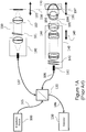
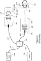
- FIG. 1A a block diagram of a conventional retinal OCT imaging system will be discussed.
- the system includes a broadband source 100 delivered over a source path 105 that may include an optical fiber, a reference arm 107 and a sample arm 108 coupled to each other by a beamsplitter 120.
- the beamsplitter 120 may be, for example, a fiber optic coupler or a bulk or micro-optic coupler.
- the beamsplitter 120 may provide from about a 50/50 to about a 90/10 split ratio.
- the beamsplitter 120 is also coupled to a wavelength or frequency sampled detection module 130 over a detection path 106 that may be provided by an optical fiber.
- the sample arm 108 couples an optical fiber to an optical assembly that shapes the spatial profile of the beam of optical radiation emitted from the optical fiber.
- the optical assembly may commonly be specified as a collimator 141 at the input to the sample arm imaging optic 140 that delivers collimated light to a pair of scanning mirrors 142, through imaging lenses that include a final objective 144.
- the optical beam delivered from the optical fiber through final objective is collimated and at least nominally telecentric.
- emmetropic refers to the clinical condition of normal uncorrected sight, i.e., the ability to focus on distant objects without supplemental correction
- telecentric refers to an optical system in which the chief rays are parallel to the optical axis across the field of view.
- the collimated light is focused through the cornea 195 and crystalline lens 193 of the subject to the retina 196.
- the scanning mirror assembly (scanning mirrors) 142 By imaging the scanning mirror assembly (scanning mirrors) 142 to the pupil 194 of the subject, the scanned beam pivots through the pupil to image the retinal plane with the minimum vignetting.
- the resultant image is a depth resolved image of the subject in a window 170 related to the path matching condition 150 with the setting of the reference arm optics 110.
- the eye focuses the beam onto the retina
- the path matching condition is defined by the reference path length and the sample arm path length, including the length of the eye
- the lateral resolution and depth of field of the scanning beam are constrained by the diameter of the beam at cornea.
- a typical reference arm assembly 110 will have an input collimator 180, a variable optical attenuator 181, and a retroreflector assembly 182.
- the retroreflector may be coupled to a movable assembly 183 for adjustment to variations in eye length, or more generally to match the reference arm path length to the sample arm path position 197.
- Correction for refractive errors of the subject is generally addressed through one or more movable lens elements 143 associated with the objective lens group 144. It is frequently desirable to be able to image without mydriasis (dialation of the eye), constraining the beam diameter to less than about 3 mm.
- an SLO is quite similar to the OCT system of Figure 1A .
- an SLO incorporates a direct detection system 131 instead of an interferometric detection system discussed with respect to the OCT system above.
- the SLO system does not have a reference arm.
- an SLO system typically uses a narrow linewidth laser source instead of a broadband source.
- the optical imaging attributes of an SLO system are nominally equivalent to an OCT system, except that the SLO system obtains a fundic image integrated over the confocal depth of field 171 instead of the depth-resolved image of the OCT system.
- focal control is required, first to compensate in refractive deviations from emmetropia, and second to control the region of interest in imaging.
- Focal control in such scanning beam retinal imaging systems is generally accomplished through relative position control 143 of the final objective 144. This focal control impacts the conjugate of the scan mirrors 142 as well as the beam focus, and requires coordination of focus and working distance, and, for OCT, the reference arm path length.
- uveitis refers to a clinical condition of inflammation of the uvea, or middle portions of the eye.
- focal control may be mediated without introducing vignetting or changing the working distance.
- Embodiments of the present inventive concept address some of these shortcomings of conventions systems.
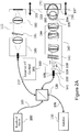
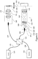
- systems including a hybrid telescope (HT) in accordance with some embodiments of the present inventive concept will be discussed.
- a HT 300 is inserted between the collimator 141 and the scan mirror assembly 142.
- the portion of the system following the beam splitter 120 in the sample arm may be referred to as "a beam shaping optical assembly" in the sample arm 108 of the OCT imaging system.
- the beam shaping optical assembly includes the collimator 141 and the HT.
- the beam shaping optical assembly may be configured to receive optical radiation from the source as a beam of optical radiation and to shape the spatial profile of the beam of optical radiation.
- the HT includes first through third lenses 310, 320 and 330. As illustrated therein, the first positive lens 310 is followed by the second, movable, negative lens 320 and the third, movable, positive lens 330. These lenses may be driven by, for example, a piezo translator or stepper motor, and may have a range of a few millimeters to one hundred or more millimeters, with a precision of a few micrometers or one or more millimeters.
- An external HT controller 301 may be provided to allow adjustment of the NA and/or focus by moving the lenses of the HT 300.
- the beam shaping optical assembly includes a lens assembly that may be configured to change a numerical aperture (NA) of the OCT system without changing a focus of the OCT system; a focus of the OCT system without changing a NA of the system; or both the NA and the focus of the OCT system responsive to a control input.
- NA numerical aperture
- Positioning the HT following a collimated input allows the HT to act as a lens with deterministic aperture and divergence that can readily be modeled through the rest of the optical system. Because the beam is tailored before the scanning system, objective lens focusing of the objective lens assembly_may not be required, and focus and zoom may be controlled at fixed working distances and path length relative to the subject. Furthermore, focus may be controlled without impacting the conjugate of the mirrors at the pupil of the eye, so that imaging conditions may be changed with a minimum of adjustment with respect to the subject.
- objective lens focal control 191 of the objective lens assembly may be used if desired. This may be advantageous for controlling the scanning mirror conjugate in relation to the pupil of the subject, the utility of which is generally overlooked, but may be beneficial when the refracting power of the cornea or anterior chamber length are different from the conditions of the design.
- the ophthalmic imaging system 140 may be adjusted with the HT 300 for a range of focusing powers between +30D to -30D, with a 3X zoom to accommodate to beam diameters at the cornea from between about 2 mm to about 6 mm, such range effectively covering 100% of the range of refractive errors in the human population, while allowing for significant ability to image structures anterior to retina within the vitreous.
- "vitreous" refers to the transparent gelatinous substance filling the region between the retina and the crystalline lens of the eye.
- the imaging system may be further adjusted to accommodate +60D of refractive correction, as may be required in cases of aphakia and for certain non-human animal models, such as rodents.
- Aphakia involves the absence of an ocular lens and is occasionally encountered in a subject.
- the lens of the eye contributes approximately +30 Diopters (D) to the refracting power of the eye.
- Imaging of an aphakic patient typically requires that the optical system substitute the optical power of the ocular lens.
- the subject eye is missing a natural or ersatz lens 194 (shown in Figure 2A ), and thus requires and additional level of focal power to successfully image the retina
- the HT 300 provides a range of focusing powers between +60D to -30D to accommodate an extended range of human and non-human refraction, including aphakia.
- the HT 300 provides a range of focusing powers between +40D to -20D to accommodate the range of human refraction, including aphakia, while the final objective 144 provides a supplemental focusing range of +20D to -10D through relative motion 191 between elements of the objective lens group.
- optical system may include a refractive bias.
- a rodent may nominally require 60D to 90D of focal power for retina imaging, and a rabbit may require 6D.
- An optical system may thus include a bias for the nominal refraction of the subject, with HT offering a range of controls relevant to the species.
- a cornea imaging system is typically a fixed focus, fixed numerical aperture system with a fixed resolution, magnification, field of view and depth of field. Different lenses may be adapted for changes in depth of field.
- Such a system while indicated for cornea, may be used in many other applications where imaging through a constricted pupil, and therefore imaging a scan plane to a conjugate pupil, may not be required.
- Applications other than anterior ocular imaging may include, for example, dermal imaging.
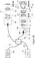
- FIG. 4 a block diagram of an imaging system in accordance with some embodiments of the present inventive concept utilizing focal and numerical aperture control for anterior ocular imaging will be discussed.
- a HT 300 according to embodiments of the present inventive concept is inserted between the collimator 141 and the scan mirror assembly 142.
- the first positive lens 310 is followed by the second, movable, negative lens 320 and the third, movable, positive lens 330.
- These lenses may be driven by, for example, a piezo translator or stepper motor, and may have a range of a few millimeters to ten or more millimeters, with a precision of a fraction or a millimeter.
- the HT 300 following a collimated input 141 acts as a lens with deterministic aperture and divergence that can readily be modeled through the rest of the optical system.
- a beam expander 530 which may be, for example, a Keplerian telescope, follows the HT 300, and in embodiments illustrated in Figure 5 , follows the scanning mirror 142.
- the geometry illustrated in Figure 5 may provide the advantage of reducing the size of mirror required to achieve beam dimensions desired at the exit pupil of the system. For example, in the ocular imaging examples discussed it is often desirable to keep the mirror dimensions below 6 mm, and often at or below 3 mm. In such circumstances, a 3X - 5X zoom relay may be advantageous.
- an endoscope for many applications, including laparoscopy in medical imaging and horoscopes for industrial imaging.
- a scanning system with miniature scanners for example, micro-electro-mechanical systems (MEMS) scanners with mirrors as small as 1.0 mm, and followed by one or more relay telescopes with desired magnifications can provide a very useful endoscope with variable focal distance and depth of field for both direct and interferometric detection implementations.
- MEMS micro-electro-mechanical systems
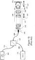
- Figure 6 illustrates a laser delivery application.
- the HT 300 in accordance with embodiments of the present inventive concept positioned in the laser delivery system allows control of both maximum intensity and beam waist.
- embodiments of the present inventive concept may be used with scanning or non-scanning geometries, and with or without following relays or beam expanders.
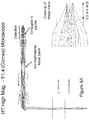
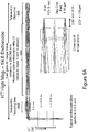
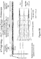
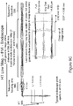
- FIGS 7A-7F systems including a HT in accordance with embodiments of the present inventive concept will be discussed.
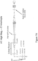
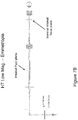
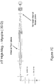
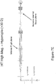
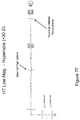
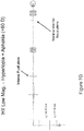
- a specific implementation of a retinal imaging system using a HT with 3X relay beam expander, a full focal range of +30D to -30D, and a 3X magnification range will be discussed with respect to Figures 7A-7F .
- NA numerical aperture
- the beam diameter at focus is 13.5 ⁇ m
- the beam diameter is reduced to 4.5 ⁇ m
- the HT lens powers and separations t1 and t2 are discussed for each of six operating conditions at the range of performance of the system.
- the positive lens groups of the HT have the same 40 mm effective focal lengths (EFL), equivalent to +20 Diopters.
- the intermediate negative lens has an effective focal length of -10mm, equivalent to -100 Diopters.
- FIG. 7G a diagram of an example implementation of a retinal imaging system using a HT with 3X relay beam expander, with an extended focal range to +60D to -30D to accommodate a full range from myopia to aphakic hyperopia is illustrated.
- aphakic hyperopia refers to clinical condition of severe farsightedness in a patient missing a natural or replacement intraocular lens.
- FIGS 8A and 8B diagrams illustrating example implementations of a scanning microscope imaging system suitable to high resolution cornea imaging will be discussed.
- the system has an effective f-number range of 1.4 to 4 and a zoom range of approximately 3X, providing imaging attributes suitable for the cellular imaging of a corneal confocal microscope at the high numerical aperture (NA) end of the range and full thickness cornea image at the low NA end of the range.
- NA numerical aperture
- the cornea imaging system includes an infinity corrected microscope objective at 3.2 mm working distance, an approximate 3X zoom (numerical aperture or beam diameter range), and field of view of 1.2 mm.
- the beam has a diffraction limited diameter of 1.4 ⁇ m and a depth of field of 14 ⁇ m.
- the beam has a diffraction limited diameter of 4.2 ⁇ m and a depth of field of 124 ⁇ m. The ability to switch between these modes of imaging offers a significant clinical advantage in providing a single tool for cellular level imaging and tomographic imaging.
- This configuration can fold into the infinity space of a stereo zoom microscope for simultaneous full field visual and video imagery, coincident with the multi-range scanning optical imagery.
- the endoscope configuration comprises a HT 300, followed by a telecentric mirror relay (telecentric focusing lens) 990, and a Hopkins-style endoscope relay 993 followed by a final telecentric objective 995, offering a 30 cm long scanning beam rigid endoscope with variable NA and focal length.
- a telecentric mirror relay telecentric focusing lens
- a Hopkins-style endoscope relay 993 followed by a final telecentric objective 995, offering a 30 cm long scanning beam rigid endoscope with variable NA and focal length.
- Operations begin at block 1000 by setting an endoscope HT to a long focal length and low NA upon entry into a region of interest to maximize the initial imaging range of the system.
- the NA is increased; reducing the depth of field but increasing the brightness along the focal plane (block 1010).
- the focal length is varied to allow the endoscope to be used with tools, such as biopsy forceps, such that the focal length matches the working distance of, for example, the forceps or the like (block 1020).
- the numerical aperture and the focal length may be changed as desired to look at structures around the target region of interest (block 1030).
- some embodiments of the present inventive concept are used in conjunction with an OCT system.
- the reference arm is coordinated to maintain the region of interest within the interferometric window. This endoscope system may be equally useful for non-interferometric scanning beam imaging systems, and for laser delivery systems.
- Example embodiments are described above with reference to block diagrams and/or flowchart illustrations of systems and devices.
- the functions/acts noted in the blocks may occur out of the order noted in the flowcharts.
- two blocks shown in succession may in fact be executed substantially concurrently or the blocks may sometimes be executed in the reverse order, depending upon the functionality/acts involved.
- the functionality of a given block of the flowcharts and/or block diagrams may be separated into multiple blocks and/or the functionality of two or more blocks of the flowcharts and/or block diagrams may be at least partially integrated.
Claims (8)
- Un système de faisceau à balayage optique comprenant:un collimateur (141) configuré pour recevoir une fibre optique couplée à une source (100) du système;un ensemble de miroirs de balayage (142) couplé au collimateur (141) du systèmeun ensemble focal précédant l'ensemble de miroir de balayage (142) du système entre le collimateur (141) et l'ensemble de miroir de balayage (142),dans lequel l'ensemble focal est configuré pour changer à la fois une ouverture numérique, NA, du système et un foyer du système en réponse à une entrée de commande,caractérisé en ce que l'ensemble focal comprend un télescope hybride (300), HT, le HT (300) comprenant :une première lentille positive (310) suivant le collimateur (141);une deuxième lentille négative (320), mobile, qui suit la première lentille positive (310); etune troisième lentille positive mobile (330) qui suit la deuxième lentille négative mobile (330) et précède le l'ensemble de miroir de balayage (142).
- Le système de la revendication 1, dans lequel le système de faisceau de balayage comprend un système de tomographie à cohérence optique, un système de livraison de laser ou un système d'imagerie endoscopique.
- Le système de la revendication 1, comprenant en outre un contrôleur (301) configuré pour déplacer la deuxième et/ou la troisième lentille (320, 330) afin d'ajuster la NA et le foyer.
- Le système de la revendication 3, dans lequel le contrôleur (301) comprend un traducteur piézoélectrique ou un moteur pas à pas.
- Le système de la revendication 3 ou 4, dans lequel le contrôleur (301) est contrôlé par un utilisateur externe au système.
- Le système de l'une des revendications précédentes, dans lequel le système est configuré pour recevoir des optiques supplémentaires après l'ensemble de miroir de balayage (142).
- Procédé pour faire fonctionner un système de faisceau de balayage, le procédé comprenant: le réglage d'un télescope hybride (300), HT, à une longue distance focale et une faible ouverture numérique, NA, lors de l'entrée dans une région d'intérêt dans un échantillon;
l'identification d'une structure de intérêt dans la région d'intérêt de l'échantillon;
l'augmentation de la NA, la réduction de la profondeur de champ et l'augmentation de la luminosité d'un plan focal; et
faire varier une distance focale de telle sorte que celle-ci corresponde à une distance de travail d'un outil associé au système de balayage du faisceau; dans lequel le HT est constitué par un ensemble focal configuré pour modifier à la fois le NA et un point focal du système en réponse à une entrée de commande, et
la HT (300) comprenant:une première lentille positive (310) suivant le collimateur (141);une deuxième lentille négative (320), mobile, qui suit la première lentille positive (310); etune troisième lentille positive mobile (330) qui suit la deuxième lentille négative mobile (330) et précède le l'ensemble de miroir de balayage (142). - Le système de faisceau à balayage optique de la revendication 1, comprenant en outre:une source d'entrée (100) de rayonnement optique configurée pour transmettre un faisceau optique ayant un diamètre de faisceau initial et une divergence de faisceau;un ensemble de conditionnement de faisceau ayant une entrée configurée pour recevoir le rayonnement optique de la source d'entrée (100), un moyen pour modifier le diamètre du faisceau et la divergence du faisceau, et une sortie configurée pour diriger le rayonnement optique vers un ensemble de balayage pour balayer le faisceau de rayonnement optique le long d'au moins une direction orthogonale à une direction de propagation du faisceau;un moyen de diriger le faisceau de rayonnement optique vers une région d'intérêt associée à un sujet;un moyen de collecter au moins une partie du rayonnement optique qui a été diffusé ou transmis à travers la région concernée;un moyen de détecter le rayonnement optique collecté;un moyen de traiter le rayonnement optique détecté pour produire une image dérivée d'un attribut de la région d'intérêt en réponse à une interaction du faisceau de rayonnement optique avec le sujet;un contrôleur (301) en communication avec l'ensemble de conditionnement de faisceau configuré pour commander au moins deux degrés de liberté de mouvement de l'ensemble de conditionnement de faisceau, dans lequel le contrôleur (301) est configuré pour régler le système de faisceau de balayage optique sur l'une d'une multiplicité de positions focales prescrites à une ouverture numérique fixe du système et pour régler le système de faisceau de balayage optique sur l'une d'une multiplicité d'ouvertures numériques prescrites à une position focale fixe au moyen d'un ensemble focal configuré pour changer à la fois l'ouverture numérique et le foyer du système en réponse à une entrée de commande.
Applications Claiming Priority (2)
| Application Number | Priority Date | Filing Date | Title |
|---|---|---|---|
| US201361830820P | 2013-06-04 | 2013-06-04 | |
| PCT/US2014/040836 WO2014197553A2 (fr) | 2013-06-04 | 2014-06-04 | Télescope hybride pour l'émission d'un faisceau optique, et systèmes et procédés connexes |
Publications (2)
| Publication Number | Publication Date |
|---|---|
| EP3003123A2 EP3003123A2 (fr) | 2016-04-13 |
| EP3003123B1 true EP3003123B1 (fr) | 2020-08-19 |
Family
ID=51904220
Family Applications (1)
| Application Number | Title | Priority Date | Filing Date |
|---|---|---|---|
| EP14799570.8A Active EP3003123B1 (fr) | 2013-06-04 | 2014-06-04 | Télescope hybride pour l'émission d'un faisceau optique, et systèmes et procédés connexes comprenant un système optique de mise en forme de faisceau avec un triplet de lentilles +-+, où les deuxième et troisième lentilles sont mobiles, et procédé |
Country Status (5)
| Country | Link |
|---|---|
| US (2) | US9949634B2 (fr) |
| EP (1) | EP3003123B1 (fr) |
| JP (1) | JP6373366B2 (fr) |
| CN (1) | CN105473055B (fr) |
| WO (1) | WO2014197553A2 (fr) |
Families Citing this family (20)
| Publication number | Priority date | Publication date | Assignee | Title |
|---|---|---|---|---|
| ES2805499T3 (es) * | 2014-03-18 | 2021-02-12 | Steris Instrument Man Services Inc | Endoscopio ópticamente adaptativo |
| CN104783755A (zh) * | 2015-04-29 | 2015-07-22 | 中国科学院光电技术研究所 | 自适应光学视网膜成像装置和方法 |
| JP6518132B2 (ja) * | 2015-05-26 | 2019-05-22 | 株式会社トプコン | 眼科撮影装置 |
| WO2017100485A1 (fr) * | 2015-12-08 | 2017-06-15 | The Regents Of The University Of Michigan | Dispositif de balayage 3d à mems pour endomicroscopie en coupe transversale en temps réel |
| CN106371374A (zh) * | 2016-11-07 | 2017-02-01 | 福州幻科机电科技有限公司 | 一种微创内窥镜四自由度定位机的智能控制电路系统 |
| CN110191670B (zh) * | 2017-01-19 | 2021-12-10 | 诺华股份有限公司 | 用于光学相干断层成像术扫描的方法和设备 |
| DE102017203010A1 (de) * | 2017-02-24 | 2018-08-30 | Carl Zeiss Meditec Ag | Verfahren und Anordnung zur hochauflösenden Topographie der Kornea eines Auges |
| NL2018857B1 (en) * | 2017-05-05 | 2018-11-09 | Illumina Inc | Systems and methods for improved focus tracking using a light source configuration |
| JP7031205B2 (ja) * | 2017-09-29 | 2022-03-08 | 株式会社ニデック | Oct装置 |
| JP7050282B2 (ja) | 2017-12-22 | 2022-04-08 | 株式会社トーメーコーポレーション | 光断層画像撮影装置及びそれに用いる光源装置 |
| EP3674776B1 (fr) * | 2017-12-28 | 2023-10-18 | Beijing Fanxing Guangdian Medical Treatment Equipment Co., Ltd. | Système d'endoscope et procédé de conception intégrée pour un système optique de caméra d'endoscope |
| EP3530175A1 (fr) * | 2018-02-26 | 2019-08-28 | Nokia Technologies Oy | Appareil de tomographie par cohérence optique |
| JP7103813B2 (ja) * | 2018-03-27 | 2022-07-20 | 株式会社トプコン | 眼科装置 |
| US11311187B2 (en) | 2018-04-06 | 2022-04-26 | Amo Development, Llc | Methods and systems for corneal topography with in-focus scleral imaging |
| CN108283484B (zh) * | 2018-04-08 | 2024-01-16 | 视微影像(河南)科技有限公司 | 一种oct眼底成像视度补偿光学系统 |
| EP3608625B1 (fr) * | 2018-08-07 | 2023-10-25 | Hexagon Technology Center GmbH | Système de mesure oct |
| CN109238131B (zh) * | 2018-08-09 | 2020-12-22 | 江苏度微光学科技有限公司 | 一种横向超高分辨的光学相干层析方法和系统 |
| KR102143484B1 (ko) * | 2018-11-12 | 2020-08-12 | 한국기초과학지원연구원 | 복합 현미경 시스템 |
| DE102019113975B4 (de) * | 2019-05-24 | 2023-10-19 | Abberior Instruments Gmbh | Verfahren und Vorrichtung zum Überwachen des Fokuszustands eines Mikroskops sowie Mikroskop |
| CN114486176A (zh) * | 2022-01-24 | 2022-05-13 | 执鼎医疗科技(杭州)有限公司 | 共焦距成像标定装置及标定方法 |
Family Cites Families (99)
| Publication number | Priority date | Publication date | Assignee | Title |
|---|---|---|---|---|
| US4167302A (en) | 1976-08-25 | 1979-09-11 | Tokyo Kogaku Kikai Kabushiki Kaisha | Surgical microscopes with L-shaped mounting brackets |
| US4431258A (en) | 1981-12-15 | 1984-02-14 | Gte Laboratories Incorporated | Optical fiber transmission system and dichroic beam splitter therefor |
| JPS5897730U (ja) | 1981-12-24 | 1983-07-02 | ヤマハ株式会社 | 光学式情報記録再生装置における自動焦点装置 |
| US4544243A (en) | 1984-05-24 | 1985-10-01 | Cooper Lasersonics, Inc. | Heads up display for microscope using remotely controlled instrument |
| IL77354A (en) | 1985-12-16 | 1989-10-31 | Sofin Ltd | Combiner for optical or electro-optical systems |
| US5055663A (en) | 1988-06-28 | 1991-10-08 | Asahi Kogaku Kogyo Kabushiki Kaisha | Optical scanning system and method for adjusting thereof |
| NL8803012A (nl) | 1988-12-08 | 1990-07-02 | Philips Nv | Optische aftastinrichting voorzien van een focusseerregelsysteem alsmede een geintegreerde schakeling voor toepassing in het focusseerregelsysteem. |
| US6099522A (en) | 1989-02-06 | 2000-08-08 | Visx Inc. | Automated laser workstation for high precision surgical and industrial interventions |
| US5061018A (en) | 1990-04-02 | 1991-10-29 | Time Surgical, Inc. | Microscope accessory equipment container |
| US5168386A (en) | 1990-10-22 | 1992-12-01 | Tencor Instruments | Flat field telecentric scanner |
| JPH05173087A (ja) | 1991-06-26 | 1993-07-13 | Asahi Optical Co Ltd | 自動焦点走査式光学装置 |
| DE69533903T2 (de) | 1994-08-18 | 2005-12-08 | Carl Zeiss Meditec Ag | Mit optischer Kohärenz-Tomographie gesteuerter chirurgischer Apparat |
| US5493109A (en) | 1994-08-18 | 1996-02-20 | Carl Zeiss, Inc. | Optical coherence tomography assisted ophthalmologic surgical microscope |
| US5491524A (en) | 1994-10-05 | 1996-02-13 | Carl Zeiss, Inc. | Optical coherence tomography corneal mapping apparatus |
| DE59601110D1 (de) | 1995-03-14 | 1999-02-18 | Leica Mikroskopie Sys Ag | Mikroskop, insbesondere stereomikroskop |
| WO1996036897A1 (fr) | 1995-05-17 | 1996-11-21 | Leica Ag | Microscope |
| AU3147897A (en) | 1996-05-31 | 1998-01-05 | Cinram, Inc. | System for adjusting the spot size in an optical recording system |
| US5795295A (en) | 1996-06-25 | 1998-08-18 | Carl Zeiss, Inc. | OCT-assisted surgical microscope with multi-coordinate manipulator |
| JP3925576B2 (ja) | 1997-07-24 | 2007-06-06 | 株式会社ニコン | 投影光学系、該光学系を備えた露光装置、及び該装置を用いたデバイスの製造方法 |
| US7246905B2 (en) | 1998-11-13 | 2007-07-24 | Jean Benedikt | Method and an apparatus for the simultaneous determination of surface topometry and biometry of the eye |
| DE19930408A1 (de) | 1999-07-02 | 2001-01-04 | Zeiss Carl Fa | OCT-gestütztes Chirurgiesystem |
| US6451010B1 (en) | 2000-04-14 | 2002-09-17 | Lumenis Inc. | Zoom handpiece for laser surgery |
| US6685317B2 (en) | 2000-06-13 | 2004-02-03 | Massie Research Laboratories, Inc. | Digital eye camera |
| DE10032067A1 (de) | 2000-07-01 | 2002-01-10 | Zeiss Carl | Scanner |
| US6426840B1 (en) | 2001-02-23 | 2002-07-30 | 3D Systems, Inc. | Electronic spot light control |
| JP4068371B2 (ja) | 2001-06-13 | 2008-03-26 | 株式会社トプコン | 手術用顕微鏡 |
| DE10202509A1 (de) | 2002-01-23 | 2003-07-31 | Leica Microsystems | Ophthalmo-Operationsmikroskop |
| US6741359B2 (en) | 2002-05-22 | 2004-05-25 | Carl Zeiss Meditec, Inc. | Optical coherence tomography optical scanner |
| CA2390072C (fr) * | 2002-06-28 | 2018-02-27 | Adrian Gh Podoleanu | Appareil de representation optique a pouvoir separateur en profondeur reglable et a fonctions multiples |
| AU2003261158A1 (en) | 2002-07-12 | 2004-02-02 | Joe Izatt | Method and device for quantitative image correction for optical coherence tomography |
| DE10339784B4 (de) | 2002-08-28 | 2021-09-16 | Carl Zeiss Meditec Ag | Mikroskopiesystem und Mikroskopieverfahren |
| ITTO20021007A1 (it) | 2002-11-19 | 2004-05-20 | Franco Bartoli | Apparecchiatura laser ad eccimeri e metodo di pilotaggio |
| DE10302401A1 (de) | 2003-01-21 | 2004-07-29 | Leica Microsystems (Schweiz) Ag | Operationsmikroskop |
| US7145727B2 (en) | 2003-03-07 | 2006-12-05 | Optoplex Corporation | Unpolarized beam splitter having polarization-independent phase difference when used as an interferometer |
| SG110178A1 (en) | 2003-09-30 | 2005-04-28 | Konica Minolta Opto Inc | Optical pick-up system, optical pick-up device, and optical information recording and/or reproducing apparatus |
| KR101384553B1 (ko) | 2003-10-27 | 2014-04-11 | 더 제너럴 하스피탈 코포레이션 | 주파수 영역 간섭법을 이용하여 광 영상화를 수행하는 방법 및 장치 |
| US7481536B2 (en) | 2004-02-19 | 2009-01-27 | Amo Manufacturing Usa, Llc | Methods and systems for differentiating left and right eye images |
| US20050277913A1 (en) | 2004-06-09 | 2005-12-15 | Mccary Brian D | Heads-up display for displaying surgical parameters in a surgical microscope |
| US7796243B2 (en) | 2004-06-09 | 2010-09-14 | National Research Council Of Canada | Detection and monitoring of changes in mineralized tissues or calcified deposits by optical coherence tomography and Raman spectroscopy |
| JP2006078701A (ja) * | 2004-09-08 | 2006-03-23 | Canon Inc | ズーム光学系 |
| US7669262B2 (en) | 2004-11-10 | 2010-03-02 | Allen Medical Systems, Inc. | Accessory frame for spinal surgery |
| DE102005042436C5 (de) | 2005-09-07 | 2010-05-27 | Carl Zeiss Surgical Gmbh | Ophthalmo-Operationsmikroskop mit Messeinrichtung |
| EP1806092A1 (fr) | 2006-01-10 | 2007-07-11 | Kabushiki Kaisha TOPCON | Dispositif d'observation de fond d'oeil |
| US8820929B2 (en) | 2006-01-20 | 2014-09-02 | Clarity Medical Systems, Inc. | Real-time measurement/display/record/playback of wavefront data for use in vision correction procedures |
| US7719692B2 (en) | 2006-04-28 | 2010-05-18 | Bioptigen, Inc. | Methods, systems and computer program products for optical coherence tomography (OCT) using automatic dispersion compensation |
| US7791734B2 (en) | 2006-05-02 | 2010-09-07 | Lawrence Livermore National Security, Llc | High-resolution retinal imaging using adaptive optics and Fourier-domain optical coherence tomography |
| WO2007143111A2 (fr) | 2006-06-01 | 2007-12-13 | University Of Southern California | Procédé et appareil destinés à guider une chirurgie cornéenne au laser avec mesures optiques |
| US20070291277A1 (en) | 2006-06-20 | 2007-12-20 | Everett Matthew J | Spectral domain optical coherence tomography system |
| US20080004610A1 (en) | 2006-06-30 | 2008-01-03 | David Miller | System for calculating IOL power |
| US7742174B2 (en) | 2006-07-17 | 2010-06-22 | Bioptigen, Inc. | Methods, systems and computer program products for removing undesired artifacts in fourier domain optical coherence tomography (FDOCT) systems using continuous phase modulation and related phase modulators |
| DE102006043889A1 (de) | 2006-09-19 | 2008-03-27 | Dieter Mann Gmbh | Vorrichtung und Verfahren zum Durchführen von Messungen mit einer optischen Kohärenztomographie-Vorrichtung während eines chirurgischen Eingriffs |
| DE102007019679A1 (de) | 2006-11-06 | 2008-05-15 | Carl Zeiss Surgical Gmbh | Operationsmikroskop mit OCT-System |
| DE102007019678A1 (de) | 2006-11-06 | 2008-05-08 | Carl Zeiss Surgical Gmbh | Operationsmikroskop mit OCT-System |
| DE102007019680A1 (de) | 2006-11-06 | 2008-05-08 | Carl Zeiss Surgical Gmbh | Ophthalmo-Operationsmikroskop mit OCT-System |
| DE102007019677A1 (de) | 2006-11-06 | 2008-05-08 | Carl Zeiss Surgical Gmbh | Operationsmikroskop mit OCT-System und Operationsmikroskop-Beleuchtungsmodul mit OCT-System |
| US7918898B2 (en) | 2006-11-30 | 2011-04-05 | Bloorview Kids Rehab | Artificial joint with locking mechanism |
| WO2008088868A2 (fr) | 2007-01-19 | 2008-07-24 | Bioptigen, Inc. | Procédés, systèmes et produits de programme informatique pour traiter des images générées en utilisant une tomographie à cohérence optique dans le domaine de fourier (fdoct) |
| US20100324543A1 (en) | 2007-09-18 | 2010-12-23 | Kurtz Ronald M | Method And Apparatus For Integrating Cataract Surgery With Glaucoma Or Astigmatism Surgery |
| US20100324542A1 (en) | 2007-11-02 | 2010-12-23 | Kurtz Ronald M | Method to Guide a Cataract Procedure by Corneal Imaging |
| JP5688491B2 (ja) | 2007-11-05 | 2015-03-25 | オプトス・ピーエルシー | 視力検査を行う方法 |
| EP2103249B9 (fr) | 2008-03-19 | 2016-10-19 | Carl Zeiss Meditec AG | Système de microscopie chirurgicale disposant d'une installation de tomographie à cohérence optique |
| US8348429B2 (en) | 2008-03-27 | 2013-01-08 | Doheny Eye Institute | Optical coherence tomography device, method, and system |
| DE102008041284B4 (de) | 2008-05-07 | 2010-05-27 | Carl Zeiss Surgical Gmbh | Ophthalmo-Operationsmikroskopsystem mit OCT-Messeinrichtung |
| JP5306041B2 (ja) * | 2008-05-08 | 2013-10-02 | キヤノン株式会社 | 撮像装置及びその方法 |
| US8189192B2 (en) | 2008-06-25 | 2012-05-29 | Bioptigen, Inc. | Volume phase grating spectrometers and related methods and systems |
| WO2010009450A1 (fr) | 2008-07-18 | 2010-01-21 | Doheny Eye Institute | Dispositif d’examen ophtalmique à base de tomographie de cohérence optique, procédé et système |
| CN101382644B (zh) | 2008-07-29 | 2010-11-24 | 福州福赛特光学仪器有限公司 | 眼虹膜模式识别用变焦距镜头装置 |
| US8652044B2 (en) | 2008-08-01 | 2014-02-18 | Igor Abramov | Portable non-contact tonometer and method of determining intra-ocular pressure using such |
| EP2427723B1 (fr) | 2009-05-04 | 2018-12-19 | Duke University | Procédés et produits-programmes informatiques pour correction quantitative d'image tridimensionnelle et calcul de paramètres cliniques pour la tomographie à cohérence optique |
| JP4909378B2 (ja) | 2009-06-02 | 2012-04-04 | キヤノン株式会社 | 画像処理装置及びその制御方法、コンピュータプログラム |
| JP5489539B2 (ja) | 2009-06-05 | 2014-05-14 | キヤノン株式会社 | 撮像装置、撮像装置の制御方法、octによる断層画像の形成方法 |
| JP5054072B2 (ja) | 2009-07-28 | 2012-10-24 | キヤノン株式会社 | 光断層画像撮像装置 |
| US9504608B2 (en) * | 2009-07-29 | 2016-11-29 | Alcon Lensx, Inc. | Optical system with movable lens for ophthalmic surgical laser |
| US8419721B2 (en) | 2009-07-29 | 2013-04-16 | Alcon Lensx, Inc. | Optical system for ophthalmic surgical laser |
| US8348427B2 (en) | 2009-09-22 | 2013-01-08 | Bioptigen, Inc. | Systems for extended depth fourier domain optical coherence tomography (FDOCT) and related methods |
| US20110173778A1 (en) | 2009-10-23 | 2011-07-21 | Michael Wales | Ergonomic auxiliary handle |
| WO2011050249A1 (fr) | 2009-10-23 | 2011-04-28 | Bioptigen, Inc. | Systèmes pour une tomographie complète en cohérence optique dans le domaine de fourier (fdoct) et procédés associés |
| US9492322B2 (en) | 2009-11-16 | 2016-11-15 | Alcon Lensx, Inc. | Imaging surgical target tissue by nonlinear scanning |
| JP5511324B2 (ja) | 2009-11-17 | 2014-06-04 | キヤノン株式会社 | 補償光学装置、補償光学方法、撮像装置、撮像方法 |
| JP5545630B2 (ja) | 2010-01-21 | 2014-07-09 | 株式会社ニデック | 眼科撮影装置 |
| EP3138475B1 (fr) * | 2010-01-22 | 2023-10-25 | AMO Development, LLC | Appareil de positionnement automatique d'incisions capsulorhexis laser balayées |
| JP5567847B2 (ja) | 2010-01-29 | 2014-08-06 | キヤノン株式会社 | 補償光学装置、補償光学方法、撮像装置 |
| US20120215155A1 (en) | 2010-03-19 | 2012-08-23 | Avedro Inc. | Controlled cross-linking initiation and corneal topography feedback systems for directing cross-linking |
| JP5597011B2 (ja) * | 2010-03-31 | 2014-10-01 | キヤノン株式会社 | 眼科装置及びその制御方法 |
| US20120022408A1 (en) | 2010-06-18 | 2012-01-26 | Vantage Surgical Systems, Inc. | Surgical Procedures Using Visual Images Overlaid with Visual Representations of Selected Three-Dimensional Data |
| US8425037B2 (en) | 2010-07-30 | 2013-04-23 | Adventus Technologies, Inc. | Intraoperative imaging system and apparatus |
| US8748801B2 (en) | 2010-09-26 | 2014-06-10 | Raytheon Company | Discrete wavefront sampling using a variable transmission filter |
| US20120262720A1 (en) | 2010-10-06 | 2012-10-18 | Brown William J | Optical coherence tomography imaging system |
| US20120184846A1 (en) | 2011-01-19 | 2012-07-19 | Duke University | Imaging and visualization systems, instruments, and methods using optical coherence tomography |
| JP2012152469A (ja) | 2011-01-27 | 2012-08-16 | Nidek Co Ltd | 眼科用手術顕微鏡 |
| WO2012129466A1 (fr) | 2011-03-23 | 2012-09-27 | Bioptigen, Inc. | Spectromètre à réseau linéaire de nombres d'ondes |
| DE102011109058A1 (de) | 2011-07-29 | 2013-01-31 | Carl Zeiss Meditec Ag | "Ophthalmologische Laservorrichtung und Verfahren zur Prävention und zur Behandlung von Nachstar" |
| WO2013059719A2 (fr) | 2011-10-21 | 2013-04-25 | Optimedica Corporation | Interface patient pour un diagnostic ophtalmologique et des procédures d'intervention |
| WO2013085997A1 (fr) | 2011-12-05 | 2013-06-13 | Bioptigen, Inc. | Systèmes d'imagerie optique comprenant une régulation de forme de faisceau entrant et une régulation de longueur de trajet |
| US9023016B2 (en) | 2011-12-19 | 2015-05-05 | Alcon Lensx, Inc. | Image processor for intra-surgical optical coherence tomographic imaging of laser cataract procedures |
| TWI446892B (zh) | 2011-12-23 | 2014-08-01 | Crystalvue Medical Corp | Jet pressure detection device |
| US9393155B2 (en) | 2011-12-28 | 2016-07-19 | Technolas Perfect Vision Gmbh | System and method for postoperative capsular bag control |
| US20130190737A1 (en) | 2012-01-10 | 2013-07-25 | David Muller | Application of energy in medical treatments |
| US8777412B2 (en) * | 2012-04-05 | 2014-07-15 | Bioptigen, Inc. | Surgical microscopes using optical coherence tomography and related methods |
-
2014
- 2014-06-04 EP EP14799570.8A patent/EP3003123B1/fr active Active
- 2014-06-04 US US14/295,664 patent/US9949634B2/en active Active
- 2014-06-04 JP JP2016518427A patent/JP6373366B2/ja active Active
- 2014-06-04 WO PCT/US2014/040836 patent/WO2014197553A2/fr active Application Filing
- 2014-06-04 CN CN201480032285.5A patent/CN105473055B/zh active Active
-
2017
- 2017-11-30 US US15/826,966 patent/US10271725B2/en active Active
Non-Patent Citations (1)
| Title |
|---|
| None * |
Also Published As
| Publication number | Publication date |
|---|---|
| CN105473055B (zh) | 2018-04-06 |
| JP2016523613A (ja) | 2016-08-12 |
| JP6373366B2 (ja) | 2018-08-15 |
| CN105473055A (zh) | 2016-04-06 |
| US20140354950A1 (en) | 2014-12-04 |
| US9949634B2 (en) | 2018-04-24 |
| WO2014197553A3 (fr) | 2015-04-02 |
| WO2014197553A2 (fr) | 2014-12-11 |
| US10271725B2 (en) | 2019-04-30 |
| US20180084993A1 (en) | 2018-03-29 |
| EP3003123A2 (fr) | 2016-04-13 |
Similar Documents
| Publication | Publication Date | Title |
|---|---|---|
| US10271725B2 (en) | Hybrid telescope for optical beam delivery and related systems | |
| US11931243B2 (en) | Method and apparatus for creating ocular surgical and relaxing incisions | |
| JP6353436B2 (ja) | 光コヒーレンストモグラフィ(oct)システム | |
| US10105260B2 (en) | Integrated ophthalmic surgical system | |
| US10092179B2 (en) | System for optical coherence tomography, comprising a zoomable kepler system | |
| TW201622667A (zh) | 使用黃斑接觸透鏡之oct外科可視化系統 | |
| EP3829503A1 (fr) | Système chirurgical ophtalmique laser à pleine profondeur, procédés d'étalonnage du système chirurgical et méthodes de traitement l'utilisant | |
| JP2023073345A (ja) | 再構成可能な光干渉断層撮影(oct)システム | |
| JP2020518795A6 (ja) | 再構成可能な光干渉断層撮影(oct)システム | |
| AU2018200910B2 (en) | Apparatus for creating ocular surgical and relaxing incisions | |
| AU2014221204B2 (en) | Apparatus for creating ocular surgical and relaxing incisions |
Legal Events
| Date | Code | Title | Description |
|---|---|---|---|
| PUAI | Public reference made under article 153(3) epc to a published international application that has entered the european phase |
Free format text: ORIGINAL CODE: 0009012 |
|
| 17P | Request for examination filed |
Effective date: 20151125 |
|
| AK | Designated contracting states |
Kind code of ref document: A2 Designated state(s): AL AT BE BG CH CY CZ DE DK EE ES FI FR GB GR HR HU IE IS IT LI LT LU LV MC MK MT NL NO PL PT RO RS SE SI SK SM TR |
|
| AX | Request for extension of the european patent |
Extension state: BA ME |
|
| DAX | Request for extension of the european patent (deleted) | ||
| STAA | Information on the status of an ep patent application or granted ep patent |
Free format text: STATUS: EXAMINATION IS IN PROGRESS |
|
| 17Q | First examination report despatched |
Effective date: 20181214 |
|
| 17Q | First examination report despatched |
Effective date: 20190611 |
|
| GRAP | Despatch of communication of intention to grant a patent |
Free format text: ORIGINAL CODE: EPIDOSNIGR1 |
|
| STAA | Information on the status of an ep patent application or granted ep patent |
Free format text: STATUS: GRANT OF PATENT IS INTENDED |
|
| INTG | Intention to grant announced |
Effective date: 20200221 |
|
| GRAJ | Information related to disapproval of communication of intention to grant by the applicant or resumption of examination proceedings by the epo deleted |
Free format text: ORIGINAL CODE: EPIDOSDIGR1 |
|
| STAA | Information on the status of an ep patent application or granted ep patent |
Free format text: STATUS: EXAMINATION IS IN PROGRESS |
|
| GRAR | Information related to intention to grant a patent recorded |
Free format text: ORIGINAL CODE: EPIDOSNIGR71 |
|
| GRAS | Grant fee paid |
Free format text: ORIGINAL CODE: EPIDOSNIGR3 |
|
| STAA | Information on the status of an ep patent application or granted ep patent |
Free format text: STATUS: GRANT OF PATENT IS INTENDED |
|
| GRAA | (expected) grant |
Free format text: ORIGINAL CODE: 0009210 |
|
| STAA | Information on the status of an ep patent application or granted ep patent |
Free format text: STATUS: THE PATENT HAS BEEN GRANTED |
|
| INTC | Intention to grant announced (deleted) | ||
| AK | Designated contracting states |
Kind code of ref document: B1 Designated state(s): AL AT BE BG CH CY CZ DE DK EE ES FI FR GB GR HR HU IE IS IT LI LT LU LV MC MK MT NL NO PL PT RO RS SE SI SK SM TR |
|
| INTG | Intention to grant announced |
Effective date: 20200714 |
|
| REG | Reference to a national code |
Ref country code: CH Ref legal event code: EP |
|
| REG | Reference to a national code |
Ref country code: DE Ref legal event code: R096 Ref document number: 602014069207 Country of ref document: DE |
|
| REG | Reference to a national code |
Ref country code: AT Ref legal event code: REF Ref document number: 1303002 Country of ref document: AT Kind code of ref document: T Effective date: 20200915 |
|
| REG | Reference to a national code |
Ref country code: IE Ref legal event code: FG4D |
|
| REG | Reference to a national code |
Ref country code: LT Ref legal event code: MG4D |
|
| REG | Reference to a national code |
Ref country code: NL Ref legal event code: MP Effective date: 20200819 |
|
| PG25 | Lapsed in a contracting state [announced via postgrant information from national office to epo] |
Ref country code: SE Free format text: LAPSE BECAUSE OF FAILURE TO SUBMIT A TRANSLATION OF THE DESCRIPTION OR TO PAY THE FEE WITHIN THE PRESCRIBED TIME-LIMIT Effective date: 20200819 Ref country code: LT Free format text: LAPSE BECAUSE OF FAILURE TO SUBMIT A TRANSLATION OF THE DESCRIPTION OR TO PAY THE FEE WITHIN THE PRESCRIBED TIME-LIMIT Effective date: 20200819 Ref country code: BG Free format text: LAPSE BECAUSE OF FAILURE TO SUBMIT A TRANSLATION OF THE DESCRIPTION OR TO PAY THE FEE WITHIN THE PRESCRIBED TIME-LIMIT Effective date: 20201119 Ref country code: GR Free format text: LAPSE BECAUSE OF FAILURE TO SUBMIT A TRANSLATION OF THE DESCRIPTION OR TO PAY THE FEE WITHIN THE PRESCRIBED TIME-LIMIT Effective date: 20201120 Ref country code: HR Free format text: LAPSE BECAUSE OF FAILURE TO SUBMIT A TRANSLATION OF THE DESCRIPTION OR TO PAY THE FEE WITHIN THE PRESCRIBED TIME-LIMIT Effective date: 20200819 Ref country code: FI Free format text: LAPSE BECAUSE OF FAILURE TO SUBMIT A TRANSLATION OF THE DESCRIPTION OR TO PAY THE FEE WITHIN THE PRESCRIBED TIME-LIMIT Effective date: 20200819 Ref country code: NO Free format text: LAPSE BECAUSE OF FAILURE TO SUBMIT A TRANSLATION OF THE DESCRIPTION OR TO PAY THE FEE WITHIN THE PRESCRIBED TIME-LIMIT Effective date: 20201119 Ref country code: PT Free format text: LAPSE BECAUSE OF FAILURE TO SUBMIT A TRANSLATION OF THE DESCRIPTION OR TO PAY THE FEE WITHIN THE PRESCRIBED TIME-LIMIT Effective date: 20201221 |
|
| REG | Reference to a national code |
Ref country code: AT Ref legal event code: MK05 Ref document number: 1303002 Country of ref document: AT Kind code of ref document: T Effective date: 20200819 |
|
| PG25 | Lapsed in a contracting state [announced via postgrant information from national office to epo] |
Ref country code: LV Free format text: LAPSE BECAUSE OF FAILURE TO SUBMIT A TRANSLATION OF THE DESCRIPTION OR TO PAY THE FEE WITHIN THE PRESCRIBED TIME-LIMIT Effective date: 20200819 Ref country code: NL Free format text: LAPSE BECAUSE OF FAILURE TO SUBMIT A TRANSLATION OF THE DESCRIPTION OR TO PAY THE FEE WITHIN THE PRESCRIBED TIME-LIMIT Effective date: 20200819 Ref country code: RS Free format text: LAPSE BECAUSE OF FAILURE TO SUBMIT A TRANSLATION OF THE DESCRIPTION OR TO PAY THE FEE WITHIN THE PRESCRIBED TIME-LIMIT Effective date: 20200819 Ref country code: PL Free format text: LAPSE BECAUSE OF FAILURE TO SUBMIT A TRANSLATION OF THE DESCRIPTION OR TO PAY THE FEE WITHIN THE PRESCRIBED TIME-LIMIT Effective date: 20200819 Ref country code: IS Free format text: LAPSE BECAUSE OF FAILURE TO SUBMIT A TRANSLATION OF THE DESCRIPTION OR TO PAY THE FEE WITHIN THE PRESCRIBED TIME-LIMIT Effective date: 20201219 |
|
| PG25 | Lapsed in a contracting state [announced via postgrant information from national office to epo] |
Ref country code: RO Free format text: LAPSE BECAUSE OF FAILURE TO SUBMIT A TRANSLATION OF THE DESCRIPTION OR TO PAY THE FEE WITHIN THE PRESCRIBED TIME-LIMIT Effective date: 20200819 Ref country code: SM Free format text: LAPSE BECAUSE OF FAILURE TO SUBMIT A TRANSLATION OF THE DESCRIPTION OR TO PAY THE FEE WITHIN THE PRESCRIBED TIME-LIMIT Effective date: 20200819 Ref country code: EE Free format text: LAPSE BECAUSE OF FAILURE TO SUBMIT A TRANSLATION OF THE DESCRIPTION OR TO PAY THE FEE WITHIN THE PRESCRIBED TIME-LIMIT Effective date: 20200819 Ref country code: CZ Free format text: LAPSE BECAUSE OF FAILURE TO SUBMIT A TRANSLATION OF THE DESCRIPTION OR TO PAY THE FEE WITHIN THE PRESCRIBED TIME-LIMIT Effective date: 20200819 Ref country code: DK Free format text: LAPSE BECAUSE OF FAILURE TO SUBMIT A TRANSLATION OF THE DESCRIPTION OR TO PAY THE FEE WITHIN THE PRESCRIBED TIME-LIMIT Effective date: 20200819 |
|
| REG | Reference to a national code |
Ref country code: DE Ref legal event code: R097 Ref document number: 602014069207 Country of ref document: DE |
|
| PG25 | Lapsed in a contracting state [announced via postgrant information from national office to epo] |
Ref country code: ES Free format text: LAPSE BECAUSE OF FAILURE TO SUBMIT A TRANSLATION OF THE DESCRIPTION OR TO PAY THE FEE WITHIN THE PRESCRIBED TIME-LIMIT Effective date: 20200819 Ref country code: AT Free format text: LAPSE BECAUSE OF FAILURE TO SUBMIT A TRANSLATION OF THE DESCRIPTION OR TO PAY THE FEE WITHIN THE PRESCRIBED TIME-LIMIT Effective date: 20200819 Ref country code: AL Free format text: LAPSE BECAUSE OF FAILURE TO SUBMIT A TRANSLATION OF THE DESCRIPTION OR TO PAY THE FEE WITHIN THE PRESCRIBED TIME-LIMIT Effective date: 20200819 |
|
| PLBE | No opposition filed within time limit |
Free format text: ORIGINAL CODE: 0009261 |
|
| STAA | Information on the status of an ep patent application or granted ep patent |
Free format text: STATUS: NO OPPOSITION FILED WITHIN TIME LIMIT |
|
| PG25 | Lapsed in a contracting state [announced via postgrant information from national office to epo] |
Ref country code: SK Free format text: LAPSE BECAUSE OF FAILURE TO SUBMIT A TRANSLATION OF THE DESCRIPTION OR TO PAY THE FEE WITHIN THE PRESCRIBED TIME-LIMIT Effective date: 20200819 |
|
| 26N | No opposition filed |
Effective date: 20210520 |
|
| PG25 | Lapsed in a contracting state [announced via postgrant information from national office to epo] |
Ref country code: IT Free format text: LAPSE BECAUSE OF FAILURE TO SUBMIT A TRANSLATION OF THE DESCRIPTION OR TO PAY THE FEE WITHIN THE PRESCRIBED TIME-LIMIT Effective date: 20200819 |
|
| PG25 | Lapsed in a contracting state [announced via postgrant information from national office to epo] |
Ref country code: SI Free format text: LAPSE BECAUSE OF FAILURE TO SUBMIT A TRANSLATION OF THE DESCRIPTION OR TO PAY THE FEE WITHIN THE PRESCRIBED TIME-LIMIT Effective date: 20200819 |
|
| PG25 | Lapsed in a contracting state [announced via postgrant information from national office to epo] |
Ref country code: MC Free format text: LAPSE BECAUSE OF FAILURE TO SUBMIT A TRANSLATION OF THE DESCRIPTION OR TO PAY THE FEE WITHIN THE PRESCRIBED TIME-LIMIT Effective date: 20200819 |
|
| REG | Reference to a national code |
Ref country code: CH Ref legal event code: PL |
|
| REG | Reference to a national code |
Ref country code: BE Ref legal event code: MM Effective date: 20210630 |
|
| PG25 | Lapsed in a contracting state [announced via postgrant information from national office to epo] |
Ref country code: LU Free format text: LAPSE BECAUSE OF NON-PAYMENT OF DUE FEES Effective date: 20210604 |
|
| PG25 | Lapsed in a contracting state [announced via postgrant information from national office to epo] |
Ref country code: LI Free format text: LAPSE BECAUSE OF NON-PAYMENT OF DUE FEES Effective date: 20210630 Ref country code: IE Free format text: LAPSE BECAUSE OF NON-PAYMENT OF DUE FEES Effective date: 20210604 Ref country code: CH Free format text: LAPSE BECAUSE OF NON-PAYMENT OF DUE FEES Effective date: 20210630 |
|
| PG25 | Lapsed in a contracting state [announced via postgrant information from national office to epo] |
Ref country code: BE Free format text: LAPSE BECAUSE OF NON-PAYMENT OF DUE FEES Effective date: 20210630 |
|
| PG25 | Lapsed in a contracting state [announced via postgrant information from national office to epo] |
Ref country code: HU Free format text: LAPSE BECAUSE OF FAILURE TO SUBMIT A TRANSLATION OF THE DESCRIPTION OR TO PAY THE FEE WITHIN THE PRESCRIBED TIME-LIMIT; INVALID AB INITIO Effective date: 20140604 |
|
| P01 | Opt-out of the competence of the unified patent court (upc) registered |
Effective date: 20230414 |
|
| PG25 | Lapsed in a contracting state [announced via postgrant information from national office to epo] |
Ref country code: CY Free format text: LAPSE BECAUSE OF FAILURE TO SUBMIT A TRANSLATION OF THE DESCRIPTION OR TO PAY THE FEE WITHIN THE PRESCRIBED TIME-LIMIT Effective date: 20200819 |
|
| PGFP | Annual fee paid to national office [announced via postgrant information from national office to epo] |
Ref country code: FR Payment date: 20230622 Year of fee payment: 10 Ref country code: DE Payment date: 20230627 Year of fee payment: 10 |
|
| PGFP | Annual fee paid to national office [announced via postgrant information from national office to epo] |
Ref country code: GB Payment date: 20230620 Year of fee payment: 10 |