EP3002371B1 - Maschine und verfahren zur erstellung von säulen in einem boden - Google Patents
Maschine und verfahren zur erstellung von säulen in einem boden Download PDFInfo
- Publication number
- EP3002371B1 EP3002371B1 EP15187924.4A EP15187924A EP3002371B1 EP 3002371 B1 EP3002371 B1 EP 3002371B1 EP 15187924 A EP15187924 A EP 15187924A EP 3002371 B1 EP3002371 B1 EP 3002371B1
- Authority
- EP
- European Patent Office
- Prior art keywords
- perforation tool
- machine
- tool
- ground
- perforation
- Prior art date
- Legal status (The legal status is an assumption and is not a legal conclusion. Google has not performed a legal analysis and makes no representation as to the accuracy of the status listed.)
- Active
Links
- 238000000034 method Methods 0.000 title claims description 23
- 239000004566 building material Substances 0.000 claims description 26
- 238000007599 discharging Methods 0.000 claims description 5
- 238000004519 manufacturing process Methods 0.000 claims description 4
- 230000008878 coupling Effects 0.000 claims 3
- 238000010168 coupling process Methods 0.000 claims 3
- 238000005859 coupling reaction Methods 0.000 claims 3
- 239000002689 soil Substances 0.000 description 33
- 239000004567 concrete Substances 0.000 description 20
- 239000000463 material Substances 0.000 description 19
- 208000031968 Cadaver Diseases 0.000 description 10
- 239000004035 construction material Substances 0.000 description 9
- 230000002787 reinforcement Effects 0.000 description 7
- 238000010276 construction Methods 0.000 description 5
- 238000005553 drilling Methods 0.000 description 5
- 238000005520 cutting process Methods 0.000 description 4
- 238000002347 injection Methods 0.000 description 4
- 239000007924 injection Substances 0.000 description 4
- 230000035515 penetration Effects 0.000 description 3
- 238000005086 pumping Methods 0.000 description 3
- 230000006378 damage Effects 0.000 description 2
- 230000006837 decompression Effects 0.000 description 2
- 238000006073 displacement reaction Methods 0.000 description 2
- 230000006872 improvement Effects 0.000 description 2
- 239000004570 mortar (masonry) Substances 0.000 description 2
- 238000004080 punching Methods 0.000 description 2
- 230000009471 action Effects 0.000 description 1
- 239000012615 aggregate Substances 0.000 description 1
- -1 ballast Substances 0.000 description 1
- 238000009412 basement excavation Methods 0.000 description 1
- 230000009172 bursting Effects 0.000 description 1
- 238000001311 chemical methods and process Methods 0.000 description 1
- 230000001627 detrimental effect Effects 0.000 description 1
- 238000009826 distribution Methods 0.000 description 1
- 230000000694 effects Effects 0.000 description 1
- 239000011440 grout Substances 0.000 description 1
- 230000036541 health Effects 0.000 description 1
- 239000007788 liquid Substances 0.000 description 1
- 230000007246 mechanism Effects 0.000 description 1
- 239000002184 metal Substances 0.000 description 1
- 230000008569 process Effects 0.000 description 1
- 230000003014 reinforcing effect Effects 0.000 description 1
- 230000000717 retained effect Effects 0.000 description 1
- 239000004576 sand Substances 0.000 description 1
- 239000000243 solution Substances 0.000 description 1
- 239000000126 substance Substances 0.000 description 1
- 238000011144 upstream manufacturing Methods 0.000 description 1
- 230000003313 weakening effect Effects 0.000 description 1
- 238000003466 welding Methods 0.000 description 1
Images


Classifications
-
- E—FIXED CONSTRUCTIONS
- E02—HYDRAULIC ENGINEERING; FOUNDATIONS; SOIL SHIFTING
- E02D—FOUNDATIONS; EXCAVATIONS; EMBANKMENTS; UNDERGROUND OR UNDERWATER STRUCTURES
- E02D5/00—Bulkheads, piles, or other structural elements specially adapted to foundation engineering
- E02D5/22—Piles
- E02D5/34—Concrete or concrete-like piles cast in position ; Apparatus for making same
- E02D5/38—Concrete or concrete-like piles cast in position ; Apparatus for making same making by use of mould-pipes or other moulds
- E02D5/385—Concrete or concrete-like piles cast in position ; Apparatus for making same making by use of mould-pipes or other moulds with removal of the outer mould-pipes
-
- E—FIXED CONSTRUCTIONS
- E02—HYDRAULIC ENGINEERING; FOUNDATIONS; SOIL SHIFTING
- E02D—FOUNDATIONS; EXCAVATIONS; EMBANKMENTS; UNDERGROUND OR UNDERWATER STRUCTURES
- E02D15/00—Handling building or like materials for hydraulic engineering or foundations
- E02D15/02—Handling of bulk concrete specially for foundation or hydraulic engineering purposes
- E02D15/04—Placing concrete in mould-pipes, pile tubes, bore-holes or narrow shafts
-
- E—FIXED CONSTRUCTIONS
- E02—HYDRAULIC ENGINEERING; FOUNDATIONS; SOIL SHIFTING
- E02D—FOUNDATIONS; EXCAVATIONS; EMBANKMENTS; UNDERGROUND OR UNDERWATER STRUCTURES
- E02D27/00—Foundations as substructures
- E02D27/10—Deep foundations
- E02D27/12—Pile foundations
-
- E—FIXED CONSTRUCTIONS
- E02—HYDRAULIC ENGINEERING; FOUNDATIONS; SOIL SHIFTING
- E02D—FOUNDATIONS; EXCAVATIONS; EMBANKMENTS; UNDERGROUND OR UNDERWATER STRUCTURES
- E02D3/00—Improving or preserving soil or rock, e.g. preserving permafrost soil
- E02D3/02—Improving by compacting
- E02D3/08—Improving by compacting by inserting stones or lost bodies, e.g. compaction piles
-
- E—FIXED CONSTRUCTIONS
- E02—HYDRAULIC ENGINEERING; FOUNDATIONS; SOIL SHIFTING
- E02D—FOUNDATIONS; EXCAVATIONS; EMBANKMENTS; UNDERGROUND OR UNDERWATER STRUCTURES
- E02D3/00—Improving or preserving soil or rock, e.g. preserving permafrost soil
- E02D3/12—Consolidating by placing solidifying or pore-filling substances in the soil
- E02D3/126—Consolidating by placing solidifying or pore-filling substances in the soil and mixing by rotating blades
-
- E—FIXED CONSTRUCTIONS
- E02—HYDRAULIC ENGINEERING; FOUNDATIONS; SOIL SHIFTING
- E02D—FOUNDATIONS; EXCAVATIONS; EMBANKMENTS; UNDERGROUND OR UNDERWATER STRUCTURES
- E02D5/00—Bulkheads, piles, or other structural elements specially adapted to foundation engineering
- E02D5/22—Piles
- E02D5/24—Prefabricated piles
- E02D5/30—Prefabricated piles made of concrete or reinforced concrete or made of steel and concrete
-
- E—FIXED CONSTRUCTIONS
- E02—HYDRAULIC ENGINEERING; FOUNDATIONS; SOIL SHIFTING
- E02D—FOUNDATIONS; EXCAVATIONS; EMBANKMENTS; UNDERGROUND OR UNDERWATER STRUCTURES
- E02D5/00—Bulkheads, piles, or other structural elements specially adapted to foundation engineering
- E02D5/22—Piles
- E02D5/34—Concrete or concrete-like piles cast in position ; Apparatus for making same
- E02D5/36—Concrete or concrete-like piles cast in position ; Apparatus for making same making without use of mouldpipes or other moulds
-
- E—FIXED CONSTRUCTIONS
- E02—HYDRAULIC ENGINEERING; FOUNDATIONS; SOIL SHIFTING
- E02D—FOUNDATIONS; EXCAVATIONS; EMBANKMENTS; UNDERGROUND OR UNDERWATER STRUCTURES
- E02D5/00—Bulkheads, piles, or other structural elements specially adapted to foundation engineering
- E02D5/66—Mould-pipes or other moulds
- E02D5/665—Mould-pipes or other moulds for making piles
-
- E—FIXED CONSTRUCTIONS
- E02—HYDRAULIC ENGINEERING; FOUNDATIONS; SOIL SHIFTING
- E02D—FOUNDATIONS; EXCAVATIONS; EMBANKMENTS; UNDERGROUND OR UNDERWATER STRUCTURES
- E02D7/00—Methods or apparatus for placing sheet pile bulkheads, piles, mouldpipes, or other moulds
- E02D7/22—Placing by screwing down
Definitions
- the present invention relates to the field of soil improvement techniques and that of deep foundations.
- soil improvement techniques aim at consolidating land with a heterogeneous structure, especially when they are inconstructible.
- the present invention more specifically relates to a machine for producing rigid structures in a soil, and a method using said machine.
- the cured material coppicing also presents problems related to the safety and health of the operators (noise and vibration for the use of jackhammers, projection risk for chemical processes).
- the coppicing of fresh material involves large-scale excavations that destroy the soil and destabilize the working platform.
- An object of the invention is to provide a machine and a method for producing rigid structures in a floor, in particular low pile structures, which overcome the drawbacks of the aforementioned prior art.
- the body being secured in translation to the perforation tool, it is not necessary to provide additional means of movement of the body in the longitudinal direction of the mast.
- the machine therefore has a limited number of components, which simplifies its assembly, and makes it easier to use.
- the fastening system is capable, in a first configuration, of fastening the perforating tool and the body in rotation about the longitudinal axis in at least one direction of rotation and in translation along the longitudinal axis. , and, in a second configuration, to release said rotational and translational movements.
- a fastening system that can be used is a bayonet system.
- the perforation tool and the body can thus be introduced together into the ground in the secured state, and can then be detached so that the perforating tool can penetrate the ground deeper than the body, by sliding through the latter. .
- the machine according to the invention thus makes it possible to carry out in the ground with a single tooling, in a single phase and with precision, a column comprising a lower portion made with the perforation tool, and an upper portion produced by the introduced body. in the ground.
- the geometric shape of the upper portion of the column corresponds to the geometric shape (imprint) of the body.
- the upper portion of the column has a diameter greater than that of the lower portion.
- the machine according to the invention makes it possible for example to form so-called mixed columns, a lower portion of which consists of a first building material and of which an upper portion is consisting of at least a second material of construction different from the first.
- the first material is usually concrete or mortar
- the second material is generally a filling material such as ballast, aggregates, sand, liquid fill, grout or mortar.
- the machine according to the invention therefore makes it possible to produce in the ground rigid structures surmounted by a filling material that can be temporary (because intended solely to temporarily seal the borehole formed to produce the structure, and to avoid the pollution of the structure ) or intended to stay permanently in particular to form a force distribution mattress or a column head. It is understood that the base of the structure is then at the junction between the lower portion and the upper portion of the column. The level of the arase, which corresponds to the level of the lower end of the body once introduced into the ground, can thus be determined with precision.
- the machine thus comprises means for supplying a first building material connected to the upper end of the perforating tool, and means for supplying at least a second material of construction different from the first, connected for example to the upper end of the perforation tool or to the body.
- the body, rotated, can penetrate the soil to a high depth, including when it has a large diameter.
- the machine according to the invention is therefore suitable for producing so-called low pile structures.
- it makes it possible to produce such a structure with a single tool, in a single phase, and in a safe manner.
- the machine according to the invention also makes it possible, as will be described hereinafter, to produce mono-material columns, called bi-diameter columns or piles, comprising a lower portion and an upper portion of diameter greater than the lower portion.
- the lower portion and the upper column portion are made of the same construction material.
- the body is not attached to the mast. More particularly, the body is never attached to the lower end of the mast. It is independent of the mast.
- the body is not connected directly to the mast, nor is it connected to the mast via an intermediate device attached to the lower end of the mast. The body is only connected to the mast via the perforation tool and the fastening system.
- the mast is preserved from vibration forces that could damage it.
- the machine further comprises a second rotation drive system, mounted on the mast, configured to drive the body in rotation.
- the second rotation drive system increases the torque applied to the body, which can be advantageous or necessary, especially when the body must be introduced into the ground to a high depth.
- the means for moving the body in the longitudinal direction of the mast are formed by the perforating tool.
- the second rotary drive system is for example mounted on a carriage, itself mounted free in translation along the mast and adapted to be driven in the longitudinal direction of the mast by the body and the punching tool. In other words, there are no other means for moving the body in translation along the mast, in particular mounted on the mast.
- the rotary perforation tool is advantageously of the type comprising a central core extending along the longitudinal axis and surrounded by a helical blade, forming an auger.
- the perforation tool is a discharge auger, the penetration into the soil causes a lateral clamping of the soil without vibration or remounting of cuttings along the borehole.
- the body generally includes a cylindrical outer shell for contacting the ground and extending around the perforating tool. It is understood that when the body and the perforation tool are secured, the rotation of the perforation tool is transmitted to the outer casing of the body, which then rotates in contact with the ground.
- the outer casing carries for example, on its outer face, a helical blade.
- the outer shell is, for example, in the form of a substantially constant circular section tube.
- the upper column portion prefferably has a diameter substantially larger than the lower column portion. This is particularly the case when it is desired to make bi-diameter piles.
- the diameter of the outer casing is at least 1.2 times greater than the diameter of the perforating tool, preferably at least 1.5 times greater than this diameter.
- the diameter of the perforation tool is defined as its maximum outside diameter.
- the body further includes an inner wall disposed between the outer shell and the perforation tool.
- the body may be intended to receive a second construction material, and may be provided at its lower end with an opening for discharging said second material.
- the space defined between the outer envelope and the inner wall is then intended to receive the second material, before it is discharged through the opening.
- the perforation tool further comprises a shutter capable of closing the orifice.
- said shutter is arranged in such a way that it closes the orifice when the lower end of the perforation tool comes into contact with the lower end of the body.
- step a the displacement of the perforation tool (in rotation and in translation towards the depth of the ground) is effected by moving the mobile carriage along the mast and by actuating the system. rotational drive of the tool, and this displacement of the perforation tool is transmitted to the body via the fastening system.
- the body is only driven in rotation and in translation by the perforation tool.
- the machine comprises a second rotation drive system, mounted on the mast, configured to drive the body in rotation, and during step a), the body is further driven into rotation by the second rotary drive system.
- step e) at least one second construction material is poured into the soil by raising the perforation tool and the body.
- the second building material may be different from or identical to the first building material.
- the body may be adapted to receive the second building material, and may be provided at its lower end with an opening for discharging said second building material, so that during step e), the second material is discharged through said opening.
- step e it is possible to pour the second construction material through the injection orifice of the perforating tool.
- the perforation tool is moved up to the first predetermined depth and solidarises in rotation the body and the perforation tool; then, during step e), the assembly formed by the body and the perforating tool is rotated by rotating them, while pouring into the ground the second building material.
- the method may comprise a preliminary step a0) carried out before step a) and intended to decompress the soil if it is too compact, to facilitate the introduction of the body into the soil.
- the perforation tool is first lowered into the ground at least up to the first predetermined depth, and is then raised.
- the method comprises a step subsequent to step e), during which at least one reinforcement cage is introduced into the column.
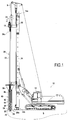
- FIG. 1 there is shown a machine 10 for producing columns in a soil S according to a first embodiment of the invention.
- the drilling machine 10 comprises a carrier 12 on which is mounted, generally in an articulated manner, a drillpole 14. On the carrier 12 may also be mounted other equipment such as the control panel of the drilling machine 10.
- a movable carriage 16 is slidably mounted along the mast 14. This sliding carriage 16 can be moved along the mast 14 by means known elsewhere and not detailed here.
- a rotation drive device in the form of a rotation head 18 is mounted on the carriage 16.
- the rotation head 18 is connected to the upper end of a tool perforation 20, that it is adapted to rotate to perform the perforation of soil S.
- the perforation tool 20 comprises a hollow central core 22 extending along a longitudinal axis X parallel to the mast 14 and delimiting a longitudinal pipe, and a cutting tool 26 at its lower end, for cutting the soil S.
- the perforation tool 20 is an auger, and more particularly a discharge auger, adapted to perforate the soil without extracting cuttings.
- This example is not, however, limiting.
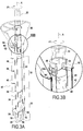
- the perforation tool 20 comprises a helical blade 24, of substantially constant diameter, extending over a lower portion 30 of the central core 22 (see in particular the figure 3A ).
- the lower portion 30 is surmounted by an upper portion 32 of greater diameter, for laterally discharging the ground cut by the helical blade 24 during drilling.
- the upper end 20a of the perforation tool 20 is connected to supply means 34 in a first building material, in this case concrete.
- the lower end 20b of the perforation tool 20 is provided with an orifice 28 for the injection of the first construction material into the soil S.
- the machine 10 further comprises a body 40, forming reservoir here, extending around the perforation tool 20.
- the body 40 has a cylindrical outer envelope 42 intended to come into contact with the ground S and extending around the perforation tool 20.
- the outer casing 42 of the body 40 is coaxial with the perforating tool 20 and carries, on its outer face, a helical blade 44, intended to facilitate the penetration, by rotation, of the body 40 in the ground.
- the diameter of the outer casing 42 is generally at least 1.2 times greater than the diameter of the perforating tool 20.
- the diameter of the outer casing is 600 mm, for a diameter of the perforation tool equal to 420 mm.
- the body 40 is intended to receive a second building material and comprises an internal wall 46 in the form of a tube disposed inside the outer envelope 42 and defining with it a space ring 48 for receiving said second material, in this case ballast. It is understood that the annular space 48 extends radially between the inner tube 46 and the outer casing 42.
- the body 40 is provided at its lower end with at least one opening (in this case two) 50 to discharge the second building material.
- the lower end of the body further comprises at least one valve (in this case two) 52 dimensioned to be able to cover the opening 50 of the body.
- each valve 52 is intended to plug an opening 50.
- each valve 52 is pivotally mounted about an axis 54 mounted on the outer casing 42.
- each valve is configured to close during the descent of the body 40 because of its support against the ground and to open gravitarily during the ascent under the effect of the thrust of the second material spilled by the corresponding opening 50.
- the upper end of the outer casing 42 is further secured to a funnel portion 56 which facilitates the filling of the body 40 with the second building material.
- the movement of the body 40 is done exclusively by means of the perforation tool 20.
- the body 40 is not mounted on the mast 14 of the machine 10. It is independent of the mast 14 .
- the machine 10 is equipped with a securing system 60 to allow the fastening of the body 40 with the perforating tool 20, in rotation and in translation.
- These securing means 60 comprise in this case at least a first element attached to or forming an integral part of the perforating tool 20 and at least a second element attached to or forming an integral part of the body 40, said elements being adapted to cooperate to form a connection with bayonet.
- the first element is a lug 62 formed at the periphery of the central core 22. More particularly, the perforation tool 20 here has two lugs, diametrically opposed.
- the second element is an L-shaped lumen 64 formed in an upper part of the body 40, of which a first branch 66, open at its lower end, extends in the longitudinal direction, and the other 68 forms a housing extending orthogonally. at said first branch 66, in the F1 direction of rotation of the body 40. More particularly, the body here has two lights 64, diametrically opposed.
- the securing means 60 may also take a different form.
- the at least one first element can be a light and the at least one second element can be a lug.
- each lug 62 abuts against the upstream wall 68b of the housing 68.
- perforation tool 20 drives the body 40 in its translational movement.
- each lug 62 is extracted from the housing 68 (lug shown in full on the figure 3B )
- the central core 22 is completely free to slide through the body 40 and free to rotate relative to the body 40. It can then, as will be described in more detail below, be lowered into the ground S up to the desired depth P2 for the column, then go up to the body by pouring the first building material through its orifice 28.
- the slots 64 are formed in an upper portion of the body 40 configured so that, regardless of the angular position of the central core 20 relative to the body 40, the lugs 62 abut against said portion in their highest position. It is thus understood that the perforation tool 20 always drives the body 40 in its upward movement along the axis X, the lugs abutting against the body 40.
- the upper portion in question here is an upper portion of the inner tube 46, of reduced internal diameter.
- a shutter 70 is pivotally mounted at the lower end 20b of the perforation tool 20, about an axis of rotation 74. More specifically, the shutter 70 has a stop surface 72 adapted, when the tool perforation 20 is raised near the body 40, to cooperate with the lower end of the inner tube 46 in a cam mechanism, to cause the rotation of the shutter 70 about the axis 74 after which the latter closes the orifice 28. Thus, the flow of the concrete is stopped.
- step (a) the carriage 16 is positioned at the top of the mast 14, so that the body 40 and the perforation tool 20, secured, are arranged out of the ground.
- step (b) the rotation head 18 is actuated and the carriage 16 is moved towards the lower end of the mast 14 so that the body 40 and the perforating tool 20 penetrate into the ground S up to a first predetermined depth P1.
- the body 40 and the perforation tool 20 are integrally rotated in the direction of the arrow F1.
- step (c) the perforation tool 20 is pivoted in the opposite direction a few degrees, so as to extract the lug 62 of the housing 68 and place it in line with the second branch 66 of the light 64.
- body 40 remains in place, and in particular does not rotate, because of the friction of the ground S against its outer casing 42.
- the body 40 and the perforation tool 20 are then in their decoupled position.
- the carriage 16 is then moved along the mast 14 towards its lower end 14b, causing the perforation tool 40 to descend into the ground S to a second depth P2 greater than the first depth P1.
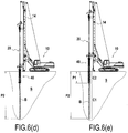
- step (d) the carriage 16 is returned to the upper end 14a of the mast 14 so as to raise the perforation tool 20.
- the shutter 70 is open and concrete B is introduced into the soil through the orifice 28, whereby a lower portion of column C1 is formed.
- the body 40 is held down in the ground on the first depth P1, and does not move.
- the shutter 70 closes when the perforation tool 20 is raised to said first depth P1.
- the perforation tool 20 is pivoted in the direction of rotation a few degrees so that the lug 62 enters the light 64 and comes finally be housed in the housing 68.
- the perforation tool 20 and the body 40 are then secured in rotation and in translation.
- step (e) the perforation tool 20 is raised while driving it in rotation.
- the ballast M is poured into the ground through the opening 50 of the body, above the lower column portion C1, so as to form the upper column portion C2.
- the entire body cavity 40 is filled with the second building material, it is also possible to fill only a part. It is understood that in this case, the upper surface of the second column is located below the surface of the ground.
- the upper portion of the column may also consist of several different materials.
- it may comprise a first section made of ballast and a second section, surmounting the first, made of a less noble material.
- step (e) we obtain the mixed column C represented on the figure 8 , consisting of a lower portion C1 concrete B, and an upper portion C2 ballast M.
- the machine 10 according to the invention also makes it possible to produce mono material columns.
- step (d) the perforation tool 20 is raised while pumping the second construction material - here concrete - into the soil S so as to form the lower portion C1 of the column .
- the concrete may be conveyed by the longitudinal pipe and poured through the orifice 28 located at the lower end 20b of the perforating tool 20.
- step (e) the assembly formed of the body 40 and the perforation tool 20 is completely raised while pumping concrete into the soil S so as to form the upper portion C2 of the column.
- the upper and lower portions are made of concrete, introduced into the ground in a single phase.
- the concrete can again be conveyed by the longitudinal pipe and then discharged through the orifice 28.
- the body 40 could be devoid of spill opening 50.
- the shutter 70 remains open to allow pumping of concrete during this ascent phase. To do this, the lower end of the perforating tool protrudes slightly from the lower end of the body so as not to cause the closing of the shutter.
- the inner wall 46 could also be omitted. According to another example of implementation, it could be provided, on the contrary, that the concrete is conveyed through the body 40, and poured through the opening 50 provided at the lower end of the body.
- the soil to be perforated, very compact makes it difficult for the body 40 to enter the soil S, in particular when the body 40 has a large diameter and the first depth P1 is high.
- a solution according to the invention may consist in carrying out a preliminary step of decompression of the soil S, before making it penetrate the secured assembly of the body 40 and the perforation tool 20 as described in connection with the step (a) above, and continue the implementation with steps (b) through (e).
- This preliminary decompression step consists in descending into the ground, generally at least to the first depth P1, the perforation tool 20 disengaged from the body 40 (remaining, itself, above the surface of the ground), then to reassemble it, before to secure the body 40 and the perforation tool 20.
- FIGS. 9A and 9B illustrate a machine 110 according to a second embodiment of the invention, and particularly suitable for producing two-diameter piles.
- This machine 110 comprises a longitudinal mast 114 fixed to a carrier 112, and a carriage 116 sliding along the mast 114, similar to the carriage 16 of the first embodiment, on which is mounted a first rotational drive system 118 allowing rotating a perforation tool 120.
- the machine 110 further comprises a body 140 similar to the body 40 of the first embodiment.
- the length of the body is here greater than in the case of the realization of a structure with low arase.
- the body here has a length of about 6 meters.
- the machine 110 differs from the previous embodiment in that it further comprises a second carriage 180, slidably mounted along the mast 114, below the first carriage 116.
- this second carriage 180 carries a second rotary drive system 182, coupled to the body 140.
- the second rotary drive system 182 here comprises a ring 184 connected to the outer casing 142 of the body 140, for example by welding on its outer surface.
- the crown is itself connected to a motor 186 rotating it.
- the body 140 being driven in translation by the perforation tool 120, the carriage 180 is here free to translate along the mast 114 being driven by the body 140. No own drive means in translation of the second carriage 180 n is provided on the machine 110.
- the second rotary drive system 182 is intended to act in addition to the perforation tool 120, which, when it is secured to the body 140, drives it into rotation.
- the torque applied to the body 140 during the drilling phase of the soil is thus increased, allowing easier drilling, especially when the body 140 is of large diameter, when the first depth P1 is high, and / or when the ground is particularly compact.
- step (a) the first carriage 116 is disposed at the upper end of the mast 114.
- the perforation tool 120 and the body 140 are in the up position, out of the ground S, and are secured.
- step (b) the perforation tool 120 is rotated and the carriage 116 is lowered towards the lower end of the mast 114, driving the assembly formed by the perforating tool 120 and the body 140 secured together with the second carriage 180 secured to the body 140.
- the second rotating head 182 rotates the body 140 in the same direction as the perforating tool 120.
- the assembly formed by the body 140 and the perforation tool 120 is lowered to the first depth P1.
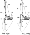
- step (c) the perforation tool 120 and the body 140 are disengaged, and the perforation tool 140 is lowered into the ground S to a second depth P2 greater than the first depth P1.
- step (d) the perforation tool 120 is raised to the depth P1, introducing concrete B into the ground, whereby a lower pile portion is formed, and then the perforation tool 120 and the body 140 are secured (in rotation and in translation).
- step (e) the assembly formed by the perforation tool 120 and the body 140 is finally wound up, while still injecting concrete B through the orifice 128 of the perforating tool, so as to form the portion upper pile.
- an additional step (f) and while the concrete is not yet hardened, to introduce in the first and / or in the second column portion at least one reinforcement cage 190, designed to strengthen the stake.
- at least in the first column portion a first reinforcement cage having a first diameter
- in the second column portion a second reinforcement cage having a larger diameter.
- the second reinforcement cage may possibly surround an upper portion of the first reinforcing cage. It is also possible to have in the first and second column portions a single cage of variable diameter reinforcement.
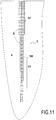
- a two-diameter concrete pile C ' is obtained, as illustrated on FIG. figure 11 , having a lower portion C1 'and an upper portion C2' of greater diameter, reinforced by metal reinforcements.
- the openings 50 and the valves 52 of the body can be omitted.
- the shutter 70 remains open by slightly letting the lower end of the perforation tool out of the body.
- machine according to this second embodiment can be used in the same way for the production of mixed columns, and in particular for the production of low-pitched concrete structures, surmounted by a temporary embankment, as described in FIG. connection with the first embodiment.
Landscapes
- Engineering & Computer Science (AREA)
- Structural Engineering (AREA)
- General Engineering & Computer Science (AREA)
- Life Sciences & Earth Sciences (AREA)
- Paleontology (AREA)
- Mining & Mineral Resources (AREA)
- General Life Sciences & Earth Sciences (AREA)
- Civil Engineering (AREA)
- Agronomy & Crop Science (AREA)
- Environmental & Geological Engineering (AREA)
- Soil Sciences (AREA)
- Piles And Underground Anchors (AREA)
- Placing Or Removing Of Piles Or Sheet Piles, Or Accessories Thereof (AREA)
Claims (18)
- Maschine (10, 110) für die Ausbildung von Säulen in einem Boden (S), umfassend:- einen Träger (12, 112), der mit einem Mast (14, 114), welcher sich in einer Längsrichtung erstreckt, ausgestattet ist,- einen beweglichen Schlitten (16, 116), der entlang des Mastes (14, 114) verschieblich angebracht ist,- ein Bodenbohrwerkzeug (20, 120), das sich entlang einer Längsachse (X) parallel zu der Längsrichtung erstreckt und mit dem beweglichen Schlitten fest verbunden ist, das ein oberes Ende (20a, 120a), welches mit Mitteln zum Zuführen eines Baumaterials verbunden ist, und ein unteres Ende, welches mit einer Öffnung (28, 128) zum Einspritzen des Baumaterials versehen ist, aufweist,- ein System zum Drehantreiben des Bohrwerkzeugs (18, 118), und- einen Körper (40, 140), der sich um das Bohrwerkzeug (20, 120) herum erstreckt, so dass das Bohrwerkzeug durch den Körper hindurch verschieblich ist,wobei die Maschine dadurch gekennzeichnet ist, dass sie ferner ein Kopplungssystem (60, 160) zur Kopplung des Körpers (40, 140) mit dem Bohrwerkzeug (20, 120) umfasst, das derart ausgestaltet ist, dass in wenigstens einer Ausführung die Rotation des Bohrwerkzeugs (20, 120) zur Rotation des Körpers (40, 140) führt und die Translation des Bohrwerkzeugs (20, 120) zur Translation des Körpers (40, 140) führt.
- Maschine (10, 110) nach Anspruch 1, bei der das Kopplungssystem (60, 160) ein Bajonett-System ist.
- Maschine (10) nach Anspruch 1 oder 2, bei der der Körper (40) nicht an dem Mast (14) befestigt ist.
- Maschine (110) nach Anspruch 1 oder 2, ferner umfassend ein an dem Mast (14, 114) angebrachtes zweites Drehantriebssystem (182), das dazu ausgelegt ist, den Körper (140) drehanzutreiben.
- Maschine (10, 110) nach einem der Ansprüche 1 bis 4, bei der das Bohrwerkzeug (20, 120) eine mittlere Seele (22, 122), die sich entlang der Längsachse (X) erstreckt und von einer spiralförmigen Schneide (24, 124) umgeben ist, umfasst.
- Maschine (10, 110) nach einem der Ansprüche 1 bis 5, bei der der Körper (40, 140) eine zylindrische Außenhülle (42, 142) umfasst, die dazu bestimmt ist, mit dem Boden in Kontakt zu gelangen, und die sich um das Bohrwerkzeug (20, 120) herum erstreckt.
- Maschine (10, 110) nach Anspruch 6, bei der der Durchmesser der Außenhülle (42, 142) wenigstens 1,2-mal größer als der Durchmesser des Bohrwerkzeugs (20, 120), vorzugsweise wenigstens 1,5-mal größer als dieser Durchmesser ist.
- Maschine (10, 110) nach Anspruch 6 oder 7, bei der die Außenhülle (42, 142) eine spiralförmige Schneide (44, 144) auf ihrer Außenseite trägt.
- Maschine (10, 110) nach einem der Ansprüche 6 bis 8, bei der der Körper (40, 140) ferner eine Innenwand (46, 146) umfasst, die zwischen der Außenhülle (42) und dem Bohrwerkzeug (20, 120) angeordnet ist.
- Maschine (10) nach einem der Ansprüche 1 bis 9, bei der der Körper (40) dazu bestimmt ist, ein zweites Baumaterial aufzunehmen, und an seinem unteren Ende mit einer Öffnung (50) zum Ausgießen des zweiten Baumaterials versehen ist.
- Maschine (10, 110) nach einem der Ansprüche 1 bis 10, bei der das Bohrwerkzeug (20, 120) ferner einen Verschluss (70), welcher geeignet ist, die Öffnung (28, 128) zu verschließen, umfasst.
- Maschine nach Anspruch 11, bei der der Verschluss (70) derart angeordnet ist, dass er die Öffnung verschließt, wenn das untere Ende des Bohrwerkzeugs (20, 120) mit dem unteren Ende des Körpers (40, 140) in Kontakt gelangt.
- Verfahren zum Ausbilden einer Säule in einem Boden mit Hilfe einer Maschine nach einem der Ansprüche 1 bis 12, bei dem:a) man das Bohrwerkzeug (20, 120) und den Körper (40, 140), die dreh- und translationsgekoppelt sind, bis zu einer vorbestimmten ersten Tiefe (P1) in den Boden drehend eindringen lässt,b) der Körper (40, 140) und das Bohrwerkzeug (20, 120) voneinander entkoppelt werden,c) das Bohrwerkzeug (20, 120) bis zu einer vorbestimmten zweiten Tiefe (P2), die größer als die erste (P1) ist, hinab bewegt wird,d) das Bohrwerkzeug (20, 120) von der vorbestimmten zweiten Tiefe (P2) aus wieder hinauf bewegt wird, gleichzeitig wird ein erstes Baumaterial durch die am unteren Ende des Bohrwerkzeugs (20, 120) befindliche Öffnung (28, 128) in den Boden eingebracht, unde) das Bohrwerkzeug (20, 120) und der Körper (40, 140) wieder hinauf bewegt werden.
- Verfahren nach Anspruch 13, bei dem während des Schrittes e) unter Hinaufbewegen des Bohrwerkzeugs (20, 120) und des Körpers (40, 140) wenigstens ein zweites Baumaterial in den Boden gegossen wird.
- Verfahren nach Anspruch 14, bei dem während des Schrittes e) das wenigstens eine zweite Baumaterial über die Öffnung (28, 128) des Bohrwerkzeugs (20, 120) ausgegossen wird.
- Verfahren nach Anspruch 14 oder 15, bei dem der Körper (40, 140) dazu bestimmt ist, das wenigstens eine zweite Baumaterial aufzunehmen, und an seinem unteren Ende mit einer Öffnung (50, 150) zum Ausgießen des zweiten Baumaterials versehen ist, und im Laufe des Schrittes e) das zweite Material über die Öffnung (50, 150) ausgegossen wird.
- Verfahren nach einem der Ansprüche 13 bis 16, das vor dem Schritt a) einen Schritt a0) umfasst, bei dem das Bohrwerkzeug (20, 120) ein erstes Mal in dem Boden wenigstens bis zu der vorbestimmten ersten Tiefe (P1) hinab bewegt, es anschließend wieder hinauf bewegt wird.
- Verfahren nach einem der Ansprüche 13 bis 17, bei dem die Maschine ein an dem Mast (14, 114) angebrachtes zweites Drehantriebssystem (182) umfasst, das dazu ausgelegt ist, den Körper (140) drehanzutreiben, und während des Schrittes a) der Körper durch das erste Drehantriebssystem (18, 118) und das zweite Drehantriebssystem (182) drehangetrieben wird.
Priority Applications (1)
| Application Number | Priority Date | Filing Date | Title |
|---|---|---|---|
| PL15187924T PL3002371T3 (pl) | 2014-10-01 | 2015-10-01 | Maszyna i sposób dla wykonywania kolumn w gruncie |
Applications Claiming Priority (1)
| Application Number | Priority Date | Filing Date | Title |
|---|---|---|---|
| FR1459355A FR3026754B1 (fr) | 2014-10-01 | 2014-10-01 | Machine et procede pour la realisation de colonnes dans un sol |
Publications (2)
| Publication Number | Publication Date |
|---|---|
| EP3002371A1 EP3002371A1 (de) | 2016-04-06 |
| EP3002371B1 true EP3002371B1 (de) | 2017-06-28 |
Family
ID=51866273
Family Applications (1)
| Application Number | Title | Priority Date | Filing Date |
|---|---|---|---|
| EP15187924.4A Active EP3002371B1 (de) | 2014-10-01 | 2015-10-01 | Maschine und verfahren zur erstellung von säulen in einem boden |
Country Status (6)
| Country | Link |
|---|---|
| US (1) | US9624638B2 (de) |
| EP (1) | EP3002371B1 (de) |
| CA (1) | CA2906244C (de) |
| FR (1) | FR3026754B1 (de) |
| HU (1) | HUE034523T2 (de) |
| PL (1) | PL3002371T3 (de) |
Families Citing this family (28)
| Publication number | Priority date | Publication date | Assignee | Title |
|---|---|---|---|---|
| US9506295B1 (en) | 2014-10-17 | 2016-11-29 | Berkel & Company Contractors, Inc. | Reversible displacement auger tool |
| US9512588B2 (en) | 2014-10-17 | 2016-12-06 | Berkel & Company Contractors, Inc. | Reversible displacement auger tool |
| ITUB20159641A1 (it) * | 2015-12-18 | 2017-06-18 | Soilmec Spa | Dispositivo e metodo per la movimentazione e l?assemblaggio reciproco di segmenti di una batteria di scavo, per esempio segmenti di elica o di asta. |
| FR3078739B1 (fr) * | 2018-03-09 | 2020-03-27 | Soletanche Freyssinet | Machine de forage comportant un dispositif de connexion pour un dispositif de mesure de verticalite |
| US10889955B2 (en) | 2018-07-30 | 2021-01-12 | Schnabel Foundation Company | Cutting tool adapter and method of underpinning structures using cutting tool adapter for soil mixing |
| US11479938B2 (en) * | 2019-03-29 | 2022-10-25 | Ojjo, Inc. | Systems, methods and machines for aligning and assembling truss foundations |
| RO134509A1 (ro) | 2019-04-08 | 2020-10-30 | Tudor Saidel | Procedeu şi dispozitiv de execuţie pe loc a unui pilot, cu diametre diferite, descrescătoare în adâncime |
| FR3097588B1 (fr) * | 2019-06-21 | 2022-03-18 | Soletanche Freyssinet | Machine pour forer un sol recouvert d’une couche poreuse, et procédé correspondant |
| CN110374097A (zh) * | 2019-07-26 | 2019-10-25 | 北京中岩大地科技股份有限公司 | 基于大直径搅拌提高桩基承载力的施工方法 |
| US11051795B2 (en) | 2019-07-31 | 2021-07-06 | Covidien Lp | Tissue retrieval bag |
| US11304687B2 (en) | 2019-08-13 | 2022-04-19 | Covidien Lp | Tissue specimen bag furling device and method |
| US11253240B2 (en) | 2019-09-10 | 2022-02-22 | Covidien Lp | Tissue specimen retrieval devices |
| US11172949B2 (en) | 2019-10-07 | 2021-11-16 | Covidien Lp | Tissue specimen retrieval devices |
| EP4055226A4 (de) | 2019-11-08 | 2023-12-20 | Ojjo, Inc. | Systeme, verfahren und maschinen für das automatische eintreiben von schraubenankern |
| US11759188B2 (en) | 2020-01-31 | 2023-09-19 | Covidien Lp | Devices, systems, and methods for specimen removal |
| US11160543B2 (en) | 2020-02-13 | 2021-11-02 | Covidien Lp | Magnetic suture tab for free standing specimen bag |
| US11224413B2 (en) | 2020-02-19 | 2022-01-18 | Covidien Lp | Retrieval device with bag release mechanism |
| US11369352B2 (en) | 2020-03-31 | 2022-06-28 | Covidien Lp | Dual channel design for free standing specimen bag |
| US11406369B2 (en) | 2020-04-08 | 2022-08-09 | Covidien Lp | Tissue specimen retrieval device with reinforced spring |
| WO2021211065A1 (en) * | 2020-04-13 | 2021-10-21 | Seafco Public Company Limited | Pile installation system and method |
| US11246613B2 (en) | 2020-05-15 | 2022-02-15 | Covidien Lp | Actuation mechanisms for tissue specimen retrieval devices and tissue specimen retrieval devices incorporating the same |
| US11304714B2 (en) | 2020-05-19 | 2022-04-19 | Covidien Lp | Tissue specimen retrieval device with assisted deployment |
| US11517297B2 (en) | 2020-06-05 | 2022-12-06 | Covidien Lp | Rollable tissue specimen bag with improved brim for tenting |
| EP4080012B1 (de) * | 2021-04-22 | 2024-05-22 | ABI Anlagentechnik-Baumaschinen-Industriebedarf Maschinenfabrik und Vertriebsgesellschaft mbH | Baumaschine für den spezialtiefbau |
| EP4098803A1 (de) * | 2021-05-31 | 2022-12-07 | ABI Anlagentechnik-Baumaschinen-Industriebedarf Maschinenfabrik und Vertriebsgesellschaft mbH | Rüttelstopflanze und verfahren zum rüsten eines mäklers mit einer rüttelstopflanze |
| CN114482027A (zh) * | 2022-03-07 | 2022-05-13 | 中部城市建设有限公司 | 一种混凝土桩身载体桩的施工方法 |
| CN114753370B (zh) * | 2022-03-23 | 2023-12-15 | 郓城县水务局 | 一种水利工程施工用物料灌浆装置及其使用方法 |
| CN115450217B (zh) * | 2022-09-06 | 2024-05-28 | 中国水电基础局有限公司 | 一种在孔口预埋管内开孔破壁灌浆的灌浆方法 |
Family Cites Families (9)
| Publication number | Priority date | Publication date | Assignee | Title |
|---|---|---|---|---|
| US3604214A (en) * | 1968-08-16 | 1971-09-14 | Lee A Turzillo | Means and method of making columnar structures in situ |
| US3512366A (en) * | 1969-02-14 | 1970-05-19 | Lee A Turzillo | Method for forming cast-in-place reinforced concrete pile |
| US3690109A (en) * | 1970-03-16 | 1972-09-12 | Lee A Turzillo | Method and means for producing pile or like structural columns in situ |
| US3886754A (en) * | 1973-07-27 | 1975-06-03 | Lee A Turzillo | Method of extending augered pile cavity through rock or like obstruction |
| JPS61207712A (ja) * | 1985-03-12 | 1986-09-16 | N I T:Kk | 地盤改良工法及びその装置 |
| US6183166B1 (en) * | 1999-04-01 | 2001-02-06 | Verne L. Schellhorn | Method of centrifugally forming a subterranean soil-cement casing |
| DE10238193B4 (de) * | 2002-08-21 | 2004-08-19 | Bauer Spezialtiefbau Gmbh | Bohrvorrichtung |
| FR2903711B1 (fr) * | 2006-07-12 | 2010-12-10 | Cie Du Sol | Outil melangeur pour le traitement d'une portion de sol. |
| FR2960571B1 (fr) * | 2010-05-27 | 2012-06-22 | Soletanche Freyssinet | Machine et procede pour la realisation de colonnes dans un sol |
-
2014
- 2014-10-01 FR FR1459355A patent/FR3026754B1/fr active Active
-
2015
- 2015-09-25 CA CA2906244A patent/CA2906244C/en active Active
- 2015-09-29 US US14/868,504 patent/US9624638B2/en active Active
- 2015-10-01 PL PL15187924T patent/PL3002371T3/pl unknown
- 2015-10-01 HU HUE15187924A patent/HUE034523T2/en unknown
- 2015-10-01 EP EP15187924.4A patent/EP3002371B1/de active Active
Non-Patent Citations (1)
| Title |
|---|
| None * |
Also Published As
| Publication number | Publication date |
|---|---|
| CA2906244A1 (en) | 2016-04-01 |
| EP3002371A1 (de) | 2016-04-06 |
| FR3026754B1 (fr) | 2016-12-02 |
| FR3026754A1 (fr) | 2016-04-08 |
| HUE034523T2 (en) | 2018-02-28 |
| US20160097177A1 (en) | 2016-04-07 |
| PL3002371T3 (pl) | 2017-12-29 |
| CA2906244C (en) | 2023-01-03 |
| US9624638B2 (en) | 2017-04-18 |
Similar Documents
| Publication | Publication Date | Title |
|---|---|---|
| EP3002371B1 (de) | Maschine und verfahren zur erstellung von säulen in einem boden | |
| EP0265344B1 (de) | Verfahren zum Herstellen eines Pfahls im Boden, sowie Bohrmaschine und Vorrichtung zur Ausführung dieses Verfahrens | |
| EP1525371A1 (de) | Teleskopführungsleitung für offshore-bohren | |
| FR2503241A1 (fr) | Dispositif a trepan pouvant etre descendu dans un puits de forage progressant dans un terrain dur, notamment du rocher, et procede pour le forage | |
| EP2156907B1 (de) | Einrichtung und Verfahren zur Bodensanierung | |
| EP2390419B1 (de) | Vorrichtung und Verfahren zum Einbringen von Säulen im Boden | |
| FR2566813A1 (fr) | Dispositif et procede pour la realisation de pieux en beton dans le sol et pieux obtenus par ce procede | |
| FR2648839A1 (fr) | Pieux de fondation, procedes, outils et machines pour la construction desdits pieux | |
| EP0382607A1 (de) | Vorrichtung zum Herstellen von Pfählen im Boden mit einem kontinuierlichen hohlen Bohrer | |
| EP1471186B1 (de) | Bohrschnecke zur Pfahlherstellung | |
| FR2874222A1 (fr) | Machine pour creuser une tranchee et realiser une paroi dans ladite tranchee | |
| EP3119939A1 (de) | Bohrungs- und betonierungsausrüstung zur herstellung eines betonpfahls im boden und zugehöriges verfahren | |
| EP2204500B1 (de) | Aushubmaschine mit schwenkbarem Kellygestänge | |
| EP2900875B1 (de) | Verfahren zur herstellung einer gründung im boden | |
| FR2800796A1 (fr) | Dispositif de forage du type a tariere | |
| EP3414399A1 (de) | Verfahren zur herstellung einer verankerungszugstange und verankerungszugstange | |
| FR2609307A1 (fr) | Dispositif d'entrainement de tariere pour le forage et le betonnage des pieux dans le sol et procede pour leur realisation | |
| FR2526855A1 (fr) | Appareil pour creuser des tunnels horizontaux | |
| EP1929094A1 (de) | Maschine zur herstellung einer durchgehenden wand im boden | |
| EP3754154B1 (de) | Maschine zum aufbohren eines mit einer porösen schicht bedeckten bodens, und entsprechendes verfahren | |
| EP3205775B1 (de) | Bohrverfahren | |
| EP3636839A1 (de) | Vorrichtung zum glätten einer säule | |
| FR2523171A1 (fr) | Procede et dispositif pour enfoncer un pieu tubulaire dans le sol | |
| BE496140A (de) | ||
| BE1006194A5 (fr) | Dispositif et procede de forage pour la formation de pieux ou analogues. |
Legal Events
| Date | Code | Title | Description |
|---|---|---|---|
| PUAI | Public reference made under article 153(3) epc to a published international application that has entered the european phase |
Free format text: ORIGINAL CODE: 0009012 |
|
| AK | Designated contracting states |
Kind code of ref document: A1 Designated state(s): AL AT BE BG CH CY CZ DE DK EE ES FI FR GB GR HR HU IE IS IT LI LT LU LV MC MK MT NL NO PL PT RO RS SE SI SK SM TR |
|
| AX | Request for extension of the european patent |
Extension state: BA ME |
|
| 17P | Request for examination filed |
Effective date: 20160919 |
|
| RBV | Designated contracting states (corrected) |
Designated state(s): AL AT BE BG CH CY CZ DE DK EE ES FI FR GB GR HR HU IE IS IT LI LT LU LV MC MK MT NL NO PL PT RO RS SE SI SK SM TR |
|
| GRAP | Despatch of communication of intention to grant a patent |
Free format text: ORIGINAL CODE: EPIDOSNIGR1 |
|
| INTG | Intention to grant announced |
Effective date: 20161202 |
|
| RIC1 | Information provided on ipc code assigned before grant |
Ipc: E02D 7/22 20060101ALI20161118BHEP Ipc: E02D 5/34 20060101ALI20161118BHEP Ipc: E02D 27/12 20060101ALI20161118BHEP Ipc: E02D 3/12 20060101ALI20161118BHEP Ipc: E02D 5/30 20060101ALI20161118BHEP Ipc: E02D 5/66 20060101ALI20161118BHEP Ipc: E02D 3/08 20060101AFI20161118BHEP Ipc: E02D 5/38 20060101ALI20161118BHEP |
|
| GRAS | Grant fee paid |
Free format text: ORIGINAL CODE: EPIDOSNIGR3 |
|
| GRAJ | Information related to disapproval of communication of intention to grant by the applicant or resumption of examination proceedings by the epo deleted |
Free format text: ORIGINAL CODE: EPIDOSDIGR1 |
|
| GRAL | Information related to payment of fee for publishing/printing deleted |
Free format text: ORIGINAL CODE: EPIDOSDIGR3 |
|
| REG | Reference to a national code |
Ref country code: DE Ref legal event code: R079 Ref document number: 602015003317 Country of ref document: DE Free format text: PREVIOUS MAIN CLASS: E02D0003080000 Ipc: E02D0005360000 |
|
| INTC | Intention to grant announced (deleted) | ||
| RIC1 | Information provided on ipc code assigned before grant |
Ipc: E02D 5/66 20060101ALI20170413BHEP Ipc: E02D 3/08 20060101ALI20170413BHEP Ipc: E02D 5/34 20060101ALI20170413BHEP Ipc: E02D 7/22 20060101ALI20170413BHEP Ipc: E02D 27/12 20060101ALI20170413BHEP Ipc: E02D 5/38 20060101ALI20170413BHEP Ipc: E02D 15/04 20060101ALI20170413BHEP Ipc: E02D 3/12 20060101ALI20170413BHEP Ipc: E02D 5/36 20060101AFI20170413BHEP Ipc: E02D 5/30 20060101ALI20170413BHEP |
|
| GRAR | Information related to intention to grant a patent recorded |
Free format text: ORIGINAL CODE: EPIDOSNIGR71 |
|
| GRAA | (expected) grant |
Free format text: ORIGINAL CODE: 0009210 |
|
| INTG | Intention to grant announced |
Effective date: 20170517 |
|
| AK | Designated contracting states |
Kind code of ref document: B1 Designated state(s): AL AT BE BG CH CY CZ DE DK EE ES FI FR GB GR HR HU IE IS IT LI LT LU LV MC MK MT NL NO PL PT RO RS SE SI SK SM TR |
|
| REG | Reference to a national code |
Ref country code: GB Ref legal event code: FG4D Free format text: NOT ENGLISH |
|
| REG | Reference to a national code |
Ref country code: CH Ref legal event code: EP |
|
| REG | Reference to a national code |
Ref country code: AT Ref legal event code: REF Ref document number: 904939 Country of ref document: AT Kind code of ref document: T Effective date: 20170715 |
|
| REG | Reference to a national code |
Ref country code: IE Ref legal event code: FG4D Free format text: LANGUAGE OF EP DOCUMENT: FRENCH |
|
| REG | Reference to a national code |
Ref country code: DE Ref legal event code: R096 Ref document number: 602015003317 Country of ref document: DE |
|
| REG | Reference to a national code |
Ref country code: FR Ref legal event code: PLFP Year of fee payment: 3 |
|
| REG | Reference to a national code |
Ref country code: RO Ref legal event code: EPE |
|
| PG25 | Lapsed in a contracting state [announced via postgrant information from national office to epo] |
Ref country code: GR Free format text: LAPSE BECAUSE OF FAILURE TO SUBMIT A TRANSLATION OF THE DESCRIPTION OR TO PAY THE FEE WITHIN THE PRESCRIBED TIME-LIMIT Effective date: 20170929 Ref country code: HR Free format text: LAPSE BECAUSE OF FAILURE TO SUBMIT A TRANSLATION OF THE DESCRIPTION OR TO PAY THE FEE WITHIN THE PRESCRIBED TIME-LIMIT Effective date: 20170628 Ref country code: NO Free format text: LAPSE BECAUSE OF FAILURE TO SUBMIT A TRANSLATION OF THE DESCRIPTION OR TO PAY THE FEE WITHIN THE PRESCRIBED TIME-LIMIT Effective date: 20170928 Ref country code: FI Free format text: LAPSE BECAUSE OF FAILURE TO SUBMIT A TRANSLATION OF THE DESCRIPTION OR TO PAY THE FEE WITHIN THE PRESCRIBED TIME-LIMIT Effective date: 20170628 Ref country code: LT Free format text: LAPSE BECAUSE OF FAILURE TO SUBMIT A TRANSLATION OF THE DESCRIPTION OR TO PAY THE FEE WITHIN THE PRESCRIBED TIME-LIMIT Effective date: 20170628 |
|
| REG | Reference to a national code |
Ref country code: NL Ref legal event code: MP Effective date: 20170628 |
|
| REG | Reference to a national code |
Ref country code: LT Ref legal event code: MG4D |
|
| REG | Reference to a national code |
Ref country code: AT Ref legal event code: MK05 Ref document number: 904939 Country of ref document: AT Kind code of ref document: T Effective date: 20170628 |
|
| PG25 | Lapsed in a contracting state [announced via postgrant information from national office to epo] |
Ref country code: LV Free format text: LAPSE BECAUSE OF FAILURE TO SUBMIT A TRANSLATION OF THE DESCRIPTION OR TO PAY THE FEE WITHIN THE PRESCRIBED TIME-LIMIT Effective date: 20170628 Ref country code: SE Free format text: LAPSE BECAUSE OF FAILURE TO SUBMIT A TRANSLATION OF THE DESCRIPTION OR TO PAY THE FEE WITHIN THE PRESCRIBED TIME-LIMIT Effective date: 20170628 Ref country code: RS Free format text: LAPSE BECAUSE OF FAILURE TO SUBMIT A TRANSLATION OF THE DESCRIPTION OR TO PAY THE FEE WITHIN THE PRESCRIBED TIME-LIMIT Effective date: 20170628 Ref country code: NL Free format text: LAPSE BECAUSE OF FAILURE TO SUBMIT A TRANSLATION OF THE DESCRIPTION OR TO PAY THE FEE WITHIN THE PRESCRIBED TIME-LIMIT Effective date: 20170628 Ref country code: BG Free format text: LAPSE BECAUSE OF FAILURE TO SUBMIT A TRANSLATION OF THE DESCRIPTION OR TO PAY THE FEE WITHIN THE PRESCRIBED TIME-LIMIT Effective date: 20170928 |
|
| PG25 | Lapsed in a contracting state [announced via postgrant information from national office to epo] |
Ref country code: CZ Free format text: LAPSE BECAUSE OF FAILURE TO SUBMIT A TRANSLATION OF THE DESCRIPTION OR TO PAY THE FEE WITHIN THE PRESCRIBED TIME-LIMIT Effective date: 20170628 Ref country code: SK Free format text: LAPSE BECAUSE OF FAILURE TO SUBMIT A TRANSLATION OF THE DESCRIPTION OR TO PAY THE FEE WITHIN THE PRESCRIBED TIME-LIMIT Effective date: 20170628 Ref country code: AT Free format text: LAPSE BECAUSE OF FAILURE TO SUBMIT A TRANSLATION OF THE DESCRIPTION OR TO PAY THE FEE WITHIN THE PRESCRIBED TIME-LIMIT Effective date: 20170628 Ref country code: EE Free format text: LAPSE BECAUSE OF FAILURE TO SUBMIT A TRANSLATION OF THE DESCRIPTION OR TO PAY THE FEE WITHIN THE PRESCRIBED TIME-LIMIT Effective date: 20170628 |
|
| PG25 | Lapsed in a contracting state [announced via postgrant information from national office to epo] |
Ref country code: ES Free format text: LAPSE BECAUSE OF FAILURE TO SUBMIT A TRANSLATION OF THE DESCRIPTION OR TO PAY THE FEE WITHIN THE PRESCRIBED TIME-LIMIT Effective date: 20170628 Ref country code: IS Free format text: LAPSE BECAUSE OF FAILURE TO SUBMIT A TRANSLATION OF THE DESCRIPTION OR TO PAY THE FEE WITHIN THE PRESCRIBED TIME-LIMIT Effective date: 20171028 Ref country code: SM Free format text: LAPSE BECAUSE OF FAILURE TO SUBMIT A TRANSLATION OF THE DESCRIPTION OR TO PAY THE FEE WITHIN THE PRESCRIBED TIME-LIMIT Effective date: 20170628 |
|
| REG | Reference to a national code |
Ref country code: HU Ref legal event code: AG4A Ref document number: E034523 Country of ref document: HU |
|
| REG | Reference to a national code |
Ref country code: DE Ref legal event code: R097 Ref document number: 602015003317 Country of ref document: DE |
|
| PG25 | Lapsed in a contracting state [announced via postgrant information from national office to epo] |
Ref country code: DK Free format text: LAPSE BECAUSE OF FAILURE TO SUBMIT A TRANSLATION OF THE DESCRIPTION OR TO PAY THE FEE WITHIN THE PRESCRIBED TIME-LIMIT Effective date: 20170628 |
|
| PLBE | No opposition filed within time limit |
Free format text: ORIGINAL CODE: 0009261 |
|
| STAA | Information on the status of an ep patent application or granted ep patent |
Free format text: STATUS: NO OPPOSITION FILED WITHIN TIME LIMIT |
|
| PG25 | Lapsed in a contracting state [announced via postgrant information from national office to epo] |
Ref country code: MC Free format text: LAPSE BECAUSE OF FAILURE TO SUBMIT A TRANSLATION OF THE DESCRIPTION OR TO PAY THE FEE WITHIN THE PRESCRIBED TIME-LIMIT Effective date: 20170628 |
|
| 26N | No opposition filed |
Effective date: 20180329 |
|
| REG | Reference to a national code |
Ref country code: IE Ref legal event code: MM4A |
|
| PG25 | Lapsed in a contracting state [announced via postgrant information from national office to epo] |
Ref country code: LU Free format text: LAPSE BECAUSE OF NON-PAYMENT OF DUE FEES Effective date: 20171001 |
|
| REG | Reference to a national code |
Ref country code: BE Ref legal event code: MM Effective date: 20171031 |
|
| PG25 | Lapsed in a contracting state [announced via postgrant information from national office to epo] |
Ref country code: SI Free format text: LAPSE BECAUSE OF FAILURE TO SUBMIT A TRANSLATION OF THE DESCRIPTION OR TO PAY THE FEE WITHIN THE PRESCRIBED TIME-LIMIT Effective date: 20170628 Ref country code: BE Free format text: LAPSE BECAUSE OF NON-PAYMENT OF DUE FEES Effective date: 20171031 |
|
| REG | Reference to a national code |
Ref country code: FR Ref legal event code: PLFP Year of fee payment: 4 |
|
| PG25 | Lapsed in a contracting state [announced via postgrant information from national office to epo] |
Ref country code: MT Free format text: LAPSE BECAUSE OF FAILURE TO SUBMIT A TRANSLATION OF THE DESCRIPTION OR TO PAY THE FEE WITHIN THE PRESCRIBED TIME-LIMIT Effective date: 20170628 |
|
| PG25 | Lapsed in a contracting state [announced via postgrant information from national office to epo] |
Ref country code: IE Free format text: LAPSE BECAUSE OF NON-PAYMENT OF DUE FEES Effective date: 20171001 |
|
| REG | Reference to a national code |
Ref country code: CH Ref legal event code: PL |
|
| PG25 | Lapsed in a contracting state [announced via postgrant information from national office to epo] |
Ref country code: CH Free format text: LAPSE BECAUSE OF NON-PAYMENT OF DUE FEES Effective date: 20181031 Ref country code: LI Free format text: LAPSE BECAUSE OF NON-PAYMENT OF DUE FEES Effective date: 20181031 |
|
| PG25 | Lapsed in a contracting state [announced via postgrant information from national office to epo] |
Ref country code: CY Free format text: LAPSE BECAUSE OF FAILURE TO SUBMIT A TRANSLATION OF THE DESCRIPTION OR TO PAY THE FEE WITHIN THE PRESCRIBED TIME-LIMIT Effective date: 20170628 |
|
| PG25 | Lapsed in a contracting state [announced via postgrant information from national office to epo] |
Ref country code: MK Free format text: LAPSE BECAUSE OF FAILURE TO SUBMIT A TRANSLATION OF THE DESCRIPTION OR TO PAY THE FEE WITHIN THE PRESCRIBED TIME-LIMIT Effective date: 20170628 |
|
| PG25 | Lapsed in a contracting state [announced via postgrant information from national office to epo] |
Ref country code: PT Free format text: LAPSE BECAUSE OF FAILURE TO SUBMIT A TRANSLATION OF THE DESCRIPTION OR TO PAY THE FEE WITHIN THE PRESCRIBED TIME-LIMIT Effective date: 20170628 |
|
| PG25 | Lapsed in a contracting state [announced via postgrant information from national office to epo] |
Ref country code: AL Free format text: LAPSE BECAUSE OF FAILURE TO SUBMIT A TRANSLATION OF THE DESCRIPTION OR TO PAY THE FEE WITHIN THE PRESCRIBED TIME-LIMIT Effective date: 20170628 |
|
| GBPC | Gb: european patent ceased through non-payment of renewal fee |
Effective date: 20191001 |
|
| PG25 | Lapsed in a contracting state [announced via postgrant information from national office to epo] |
Ref country code: GB Free format text: LAPSE BECAUSE OF NON-PAYMENT OF DUE FEES Effective date: 20191001 |
|
| REG | Reference to a national code |
Ref country code: DE Ref legal event code: R082 Ref document number: 602015003317 Country of ref document: DE Representative=s name: CBDL PATENTANWAELTE GBR, DE |
|
| P01 | Opt-out of the competence of the unified patent court (upc) registered |
Effective date: 20230528 |
|
| PGFP | Annual fee paid to national office [announced via postgrant information from national office to epo] |
Ref country code: TR Payment date: 20230922 Year of fee payment: 9 Ref country code: IT Payment date: 20230920 Year of fee payment: 9 |
|
| PGFP | Annual fee paid to national office [announced via postgrant information from national office to epo] |
Ref country code: PL Payment date: 20230925 Year of fee payment: 9 Ref country code: FR Payment date: 20230920 Year of fee payment: 9 |
|
| PGFP | Annual fee paid to national office [announced via postgrant information from national office to epo] |
Ref country code: RO Payment date: 20231002 Year of fee payment: 9 Ref country code: HU Payment date: 20231004 Year of fee payment: 9 Ref country code: DE Payment date: 20230920 Year of fee payment: 9 |