EP3002371B1 - Machine et procédé pour la réalisation de colonnes dans un sol - Google Patents
Machine et procédé pour la réalisation de colonnes dans un sol Download PDFInfo
- Publication number
- EP3002371B1 EP3002371B1 EP15187924.4A EP15187924A EP3002371B1 EP 3002371 B1 EP3002371 B1 EP 3002371B1 EP 15187924 A EP15187924 A EP 15187924A EP 3002371 B1 EP3002371 B1 EP 3002371B1
- Authority
- EP
- European Patent Office
- Prior art keywords
- perforation tool
- machine
- tool
- ground
- perforation
- Prior art date
- Legal status (The legal status is an assumption and is not a legal conclusion. Google has not performed a legal analysis and makes no representation as to the accuracy of the status listed.)
- Active
Links
- 238000000034 method Methods 0.000 title claims description 23
- 239000004566 building material Substances 0.000 claims description 26
- 238000007599 discharging Methods 0.000 claims description 5
- 238000004519 manufacturing process Methods 0.000 claims description 4
- 230000008878 coupling Effects 0.000 claims 3
- 238000010168 coupling process Methods 0.000 claims 3
- 238000005859 coupling reaction Methods 0.000 claims 3
- 239000002689 soil Substances 0.000 description 33
- 239000004567 concrete Substances 0.000 description 20
- 239000000463 material Substances 0.000 description 19
- 208000031968 Cadaver Diseases 0.000 description 10
- 239000004035 construction material Substances 0.000 description 9
- 230000002787 reinforcement Effects 0.000 description 7
- 238000010276 construction Methods 0.000 description 5
- 238000005553 drilling Methods 0.000 description 5
- 238000005520 cutting process Methods 0.000 description 4
- 238000002347 injection Methods 0.000 description 4
- 239000007924 injection Substances 0.000 description 4
- 230000035515 penetration Effects 0.000 description 3
- 238000005086 pumping Methods 0.000 description 3
- 230000006378 damage Effects 0.000 description 2
- 230000006837 decompression Effects 0.000 description 2
- 238000006073 displacement reaction Methods 0.000 description 2
- 230000006872 improvement Effects 0.000 description 2
- 239000004570 mortar (masonry) Substances 0.000 description 2
- 238000004080 punching Methods 0.000 description 2
- 230000009471 action Effects 0.000 description 1
- 239000012615 aggregate Substances 0.000 description 1
- -1 ballast Substances 0.000 description 1
- 238000009412 basement excavation Methods 0.000 description 1
- 230000009172 bursting Effects 0.000 description 1
- 238000001311 chemical methods and process Methods 0.000 description 1
- 230000001627 detrimental effect Effects 0.000 description 1
- 238000009826 distribution Methods 0.000 description 1
- 230000000694 effects Effects 0.000 description 1
- 239000011440 grout Substances 0.000 description 1
- 230000036541 health Effects 0.000 description 1
- 239000007788 liquid Substances 0.000 description 1
- 230000007246 mechanism Effects 0.000 description 1
- 239000002184 metal Substances 0.000 description 1
- 230000008569 process Effects 0.000 description 1
- 230000003014 reinforcing effect Effects 0.000 description 1
- 230000000717 retained effect Effects 0.000 description 1
- 239000004576 sand Substances 0.000 description 1
- 239000000243 solution Substances 0.000 description 1
- 239000000126 substance Substances 0.000 description 1
- 238000011144 upstream manufacturing Methods 0.000 description 1
- 230000003313 weakening effect Effects 0.000 description 1
- 238000003466 welding Methods 0.000 description 1
Images


Classifications
-
- E—FIXED CONSTRUCTIONS
- E02—HYDRAULIC ENGINEERING; FOUNDATIONS; SOIL SHIFTING
- E02D—FOUNDATIONS; EXCAVATIONS; EMBANKMENTS; UNDERGROUND OR UNDERWATER STRUCTURES
- E02D5/00—Bulkheads, piles, or other structural elements specially adapted to foundation engineering
- E02D5/22—Piles
- E02D5/34—Concrete or concrete-like piles cast in position ; Apparatus for making same
- E02D5/38—Concrete or concrete-like piles cast in position ; Apparatus for making same making by use of mould-pipes or other moulds
- E02D5/385—Concrete or concrete-like piles cast in position ; Apparatus for making same making by use of mould-pipes or other moulds with removal of the outer mould-pipes
-
- E—FIXED CONSTRUCTIONS
- E02—HYDRAULIC ENGINEERING; FOUNDATIONS; SOIL SHIFTING
- E02D—FOUNDATIONS; EXCAVATIONS; EMBANKMENTS; UNDERGROUND OR UNDERWATER STRUCTURES
- E02D15/00—Handling building or like materials for hydraulic engineering or foundations
- E02D15/02—Handling of bulk concrete specially for foundation or hydraulic engineering purposes
- E02D15/04—Placing concrete in mould-pipes, pile tubes, bore-holes or narrow shafts
-
- E—FIXED CONSTRUCTIONS
- E02—HYDRAULIC ENGINEERING; FOUNDATIONS; SOIL SHIFTING
- E02D—FOUNDATIONS; EXCAVATIONS; EMBANKMENTS; UNDERGROUND OR UNDERWATER STRUCTURES
- E02D27/00—Foundations as substructures
- E02D27/10—Deep foundations
- E02D27/12—Pile foundations
-
- E—FIXED CONSTRUCTIONS
- E02—HYDRAULIC ENGINEERING; FOUNDATIONS; SOIL SHIFTING
- E02D—FOUNDATIONS; EXCAVATIONS; EMBANKMENTS; UNDERGROUND OR UNDERWATER STRUCTURES
- E02D3/00—Improving or preserving soil or rock, e.g. preserving permafrost soil
- E02D3/02—Improving by compacting
- E02D3/08—Improving by compacting by inserting stones or lost bodies, e.g. compaction piles
-
- E—FIXED CONSTRUCTIONS
- E02—HYDRAULIC ENGINEERING; FOUNDATIONS; SOIL SHIFTING
- E02D—FOUNDATIONS; EXCAVATIONS; EMBANKMENTS; UNDERGROUND OR UNDERWATER STRUCTURES
- E02D3/00—Improving or preserving soil or rock, e.g. preserving permafrost soil
- E02D3/12—Consolidating by placing solidifying or pore-filling substances in the soil
- E02D3/126—Consolidating by placing solidifying or pore-filling substances in the soil and mixing by rotating blades
-
- E—FIXED CONSTRUCTIONS
- E02—HYDRAULIC ENGINEERING; FOUNDATIONS; SOIL SHIFTING
- E02D—FOUNDATIONS; EXCAVATIONS; EMBANKMENTS; UNDERGROUND OR UNDERWATER STRUCTURES
- E02D5/00—Bulkheads, piles, or other structural elements specially adapted to foundation engineering
- E02D5/22—Piles
- E02D5/24—Prefabricated piles
- E02D5/30—Prefabricated piles made of concrete or reinforced concrete or made of steel and concrete
-
- E—FIXED CONSTRUCTIONS
- E02—HYDRAULIC ENGINEERING; FOUNDATIONS; SOIL SHIFTING
- E02D—FOUNDATIONS; EXCAVATIONS; EMBANKMENTS; UNDERGROUND OR UNDERWATER STRUCTURES
- E02D5/00—Bulkheads, piles, or other structural elements specially adapted to foundation engineering
- E02D5/22—Piles
- E02D5/34—Concrete or concrete-like piles cast in position ; Apparatus for making same
- E02D5/36—Concrete or concrete-like piles cast in position ; Apparatus for making same making without use of mouldpipes or other moulds
-
- E—FIXED CONSTRUCTIONS
- E02—HYDRAULIC ENGINEERING; FOUNDATIONS; SOIL SHIFTING
- E02D—FOUNDATIONS; EXCAVATIONS; EMBANKMENTS; UNDERGROUND OR UNDERWATER STRUCTURES
- E02D5/00—Bulkheads, piles, or other structural elements specially adapted to foundation engineering
- E02D5/66—Mould-pipes or other moulds
- E02D5/665—Mould-pipes or other moulds for making piles
-
- E—FIXED CONSTRUCTIONS
- E02—HYDRAULIC ENGINEERING; FOUNDATIONS; SOIL SHIFTING
- E02D—FOUNDATIONS; EXCAVATIONS; EMBANKMENTS; UNDERGROUND OR UNDERWATER STRUCTURES
- E02D7/00—Methods or apparatus for placing sheet pile bulkheads, piles, mouldpipes, or other moulds
- E02D7/22—Placing by screwing down
Definitions
- the present invention relates to the field of soil improvement techniques and that of deep foundations.
- soil improvement techniques aim at consolidating land with a heterogeneous structure, especially when they are inconstructible.
- the present invention more specifically relates to a machine for producing rigid structures in a soil, and a method using said machine.
- the cured material coppicing also presents problems related to the safety and health of the operators (noise and vibration for the use of jackhammers, projection risk for chemical processes).
- the coppicing of fresh material involves large-scale excavations that destroy the soil and destabilize the working platform.
- An object of the invention is to provide a machine and a method for producing rigid structures in a floor, in particular low pile structures, which overcome the drawbacks of the aforementioned prior art.
- the body being secured in translation to the perforation tool, it is not necessary to provide additional means of movement of the body in the longitudinal direction of the mast.
- the machine therefore has a limited number of components, which simplifies its assembly, and makes it easier to use.
- the fastening system is capable, in a first configuration, of fastening the perforating tool and the body in rotation about the longitudinal axis in at least one direction of rotation and in translation along the longitudinal axis. , and, in a second configuration, to release said rotational and translational movements.
- a fastening system that can be used is a bayonet system.
- the perforation tool and the body can thus be introduced together into the ground in the secured state, and can then be detached so that the perforating tool can penetrate the ground deeper than the body, by sliding through the latter. .
- the machine according to the invention thus makes it possible to carry out in the ground with a single tooling, in a single phase and with precision, a column comprising a lower portion made with the perforation tool, and an upper portion produced by the introduced body. in the ground.
- the geometric shape of the upper portion of the column corresponds to the geometric shape (imprint) of the body.
- the upper portion of the column has a diameter greater than that of the lower portion.
- the machine according to the invention makes it possible for example to form so-called mixed columns, a lower portion of which consists of a first building material and of which an upper portion is consisting of at least a second material of construction different from the first.
- the first material is usually concrete or mortar
- the second material is generally a filling material such as ballast, aggregates, sand, liquid fill, grout or mortar.
- the machine according to the invention therefore makes it possible to produce in the ground rigid structures surmounted by a filling material that can be temporary (because intended solely to temporarily seal the borehole formed to produce the structure, and to avoid the pollution of the structure ) or intended to stay permanently in particular to form a force distribution mattress or a column head. It is understood that the base of the structure is then at the junction between the lower portion and the upper portion of the column. The level of the arase, which corresponds to the level of the lower end of the body once introduced into the ground, can thus be determined with precision.
- the machine thus comprises means for supplying a first building material connected to the upper end of the perforating tool, and means for supplying at least a second material of construction different from the first, connected for example to the upper end of the perforation tool or to the body.
- the body, rotated, can penetrate the soil to a high depth, including when it has a large diameter.
- the machine according to the invention is therefore suitable for producing so-called low pile structures.
- it makes it possible to produce such a structure with a single tool, in a single phase, and in a safe manner.
- the machine according to the invention also makes it possible, as will be described hereinafter, to produce mono-material columns, called bi-diameter columns or piles, comprising a lower portion and an upper portion of diameter greater than the lower portion.
- the lower portion and the upper column portion are made of the same construction material.
- the body is not attached to the mast. More particularly, the body is never attached to the lower end of the mast. It is independent of the mast.
- the body is not connected directly to the mast, nor is it connected to the mast via an intermediate device attached to the lower end of the mast. The body is only connected to the mast via the perforation tool and the fastening system.
- the mast is preserved from vibration forces that could damage it.
- the machine further comprises a second rotation drive system, mounted on the mast, configured to drive the body in rotation.
- the second rotation drive system increases the torque applied to the body, which can be advantageous or necessary, especially when the body must be introduced into the ground to a high depth.
- the means for moving the body in the longitudinal direction of the mast are formed by the perforating tool.
- the second rotary drive system is for example mounted on a carriage, itself mounted free in translation along the mast and adapted to be driven in the longitudinal direction of the mast by the body and the punching tool. In other words, there are no other means for moving the body in translation along the mast, in particular mounted on the mast.
- the rotary perforation tool is advantageously of the type comprising a central core extending along the longitudinal axis and surrounded by a helical blade, forming an auger.
- the perforation tool is a discharge auger, the penetration into the soil causes a lateral clamping of the soil without vibration or remounting of cuttings along the borehole.
- the body generally includes a cylindrical outer shell for contacting the ground and extending around the perforating tool. It is understood that when the body and the perforation tool are secured, the rotation of the perforation tool is transmitted to the outer casing of the body, which then rotates in contact with the ground.
- the outer casing carries for example, on its outer face, a helical blade.
- the outer shell is, for example, in the form of a substantially constant circular section tube.
- the upper column portion prefferably has a diameter substantially larger than the lower column portion. This is particularly the case when it is desired to make bi-diameter piles.
- the diameter of the outer casing is at least 1.2 times greater than the diameter of the perforating tool, preferably at least 1.5 times greater than this diameter.
- the diameter of the perforation tool is defined as its maximum outside diameter.
- the body further includes an inner wall disposed between the outer shell and the perforation tool.
- the body may be intended to receive a second construction material, and may be provided at its lower end with an opening for discharging said second material.
- the space defined between the outer envelope and the inner wall is then intended to receive the second material, before it is discharged through the opening.
- the perforation tool further comprises a shutter capable of closing the orifice.
- said shutter is arranged in such a way that it closes the orifice when the lower end of the perforation tool comes into contact with the lower end of the body.
- step a the displacement of the perforation tool (in rotation and in translation towards the depth of the ground) is effected by moving the mobile carriage along the mast and by actuating the system. rotational drive of the tool, and this displacement of the perforation tool is transmitted to the body via the fastening system.
- the body is only driven in rotation and in translation by the perforation tool.
- the machine comprises a second rotation drive system, mounted on the mast, configured to drive the body in rotation, and during step a), the body is further driven into rotation by the second rotary drive system.
- step e) at least one second construction material is poured into the soil by raising the perforation tool and the body.
- the second building material may be different from or identical to the first building material.
- the body may be adapted to receive the second building material, and may be provided at its lower end with an opening for discharging said second building material, so that during step e), the second material is discharged through said opening.
- step e it is possible to pour the second construction material through the injection orifice of the perforating tool.
- the perforation tool is moved up to the first predetermined depth and solidarises in rotation the body and the perforation tool; then, during step e), the assembly formed by the body and the perforating tool is rotated by rotating them, while pouring into the ground the second building material.
- the method may comprise a preliminary step a0) carried out before step a) and intended to decompress the soil if it is too compact, to facilitate the introduction of the body into the soil.
- the perforation tool is first lowered into the ground at least up to the first predetermined depth, and is then raised.
- the method comprises a step subsequent to step e), during which at least one reinforcement cage is introduced into the column.
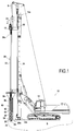
- FIG. 1 there is shown a machine 10 for producing columns in a soil S according to a first embodiment of the invention.
- the drilling machine 10 comprises a carrier 12 on which is mounted, generally in an articulated manner, a drillpole 14. On the carrier 12 may also be mounted other equipment such as the control panel of the drilling machine 10.
- a movable carriage 16 is slidably mounted along the mast 14. This sliding carriage 16 can be moved along the mast 14 by means known elsewhere and not detailed here.
- a rotation drive device in the form of a rotation head 18 is mounted on the carriage 16.
- the rotation head 18 is connected to the upper end of a tool perforation 20, that it is adapted to rotate to perform the perforation of soil S.
- the perforation tool 20 comprises a hollow central core 22 extending along a longitudinal axis X parallel to the mast 14 and delimiting a longitudinal pipe, and a cutting tool 26 at its lower end, for cutting the soil S.
- the perforation tool 20 is an auger, and more particularly a discharge auger, adapted to perforate the soil without extracting cuttings.
- This example is not, however, limiting.
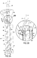
- the perforation tool 20 comprises a helical blade 24, of substantially constant diameter, extending over a lower portion 30 of the central core 22 (see in particular the figure 3A ).
- the lower portion 30 is surmounted by an upper portion 32 of greater diameter, for laterally discharging the ground cut by the helical blade 24 during drilling.
- the upper end 20a of the perforation tool 20 is connected to supply means 34 in a first building material, in this case concrete.
- the lower end 20b of the perforation tool 20 is provided with an orifice 28 for the injection of the first construction material into the soil S.
- the machine 10 further comprises a body 40, forming reservoir here, extending around the perforation tool 20.
- the body 40 has a cylindrical outer envelope 42 intended to come into contact with the ground S and extending around the perforation tool 20.
- the outer casing 42 of the body 40 is coaxial with the perforating tool 20 and carries, on its outer face, a helical blade 44, intended to facilitate the penetration, by rotation, of the body 40 in the ground.
- the diameter of the outer casing 42 is generally at least 1.2 times greater than the diameter of the perforating tool 20.
- the diameter of the outer casing is 600 mm, for a diameter of the perforation tool equal to 420 mm.
- the body 40 is intended to receive a second building material and comprises an internal wall 46 in the form of a tube disposed inside the outer envelope 42 and defining with it a space ring 48 for receiving said second material, in this case ballast. It is understood that the annular space 48 extends radially between the inner tube 46 and the outer casing 42.
- the body 40 is provided at its lower end with at least one opening (in this case two) 50 to discharge the second building material.
- the lower end of the body further comprises at least one valve (in this case two) 52 dimensioned to be able to cover the opening 50 of the body.
- each valve 52 is intended to plug an opening 50.
- each valve 52 is pivotally mounted about an axis 54 mounted on the outer casing 42.
- each valve is configured to close during the descent of the body 40 because of its support against the ground and to open gravitarily during the ascent under the effect of the thrust of the second material spilled by the corresponding opening 50.
- the upper end of the outer casing 42 is further secured to a funnel portion 56 which facilitates the filling of the body 40 with the second building material.
- the movement of the body 40 is done exclusively by means of the perforation tool 20.
- the body 40 is not mounted on the mast 14 of the machine 10. It is independent of the mast 14 .
- the machine 10 is equipped with a securing system 60 to allow the fastening of the body 40 with the perforating tool 20, in rotation and in translation.
- These securing means 60 comprise in this case at least a first element attached to or forming an integral part of the perforating tool 20 and at least a second element attached to or forming an integral part of the body 40, said elements being adapted to cooperate to form a connection with bayonet.
- the first element is a lug 62 formed at the periphery of the central core 22. More particularly, the perforation tool 20 here has two lugs, diametrically opposed.
- the second element is an L-shaped lumen 64 formed in an upper part of the body 40, of which a first branch 66, open at its lower end, extends in the longitudinal direction, and the other 68 forms a housing extending orthogonally. at said first branch 66, in the F1 direction of rotation of the body 40. More particularly, the body here has two lights 64, diametrically opposed.
- the securing means 60 may also take a different form.
- the at least one first element can be a light and the at least one second element can be a lug.
- each lug 62 abuts against the upstream wall 68b of the housing 68.
- perforation tool 20 drives the body 40 in its translational movement.
- each lug 62 is extracted from the housing 68 (lug shown in full on the figure 3B )
- the central core 22 is completely free to slide through the body 40 and free to rotate relative to the body 40. It can then, as will be described in more detail below, be lowered into the ground S up to the desired depth P2 for the column, then go up to the body by pouring the first building material through its orifice 28.
- the slots 64 are formed in an upper portion of the body 40 configured so that, regardless of the angular position of the central core 20 relative to the body 40, the lugs 62 abut against said portion in their highest position. It is thus understood that the perforation tool 20 always drives the body 40 in its upward movement along the axis X, the lugs abutting against the body 40.
- the upper portion in question here is an upper portion of the inner tube 46, of reduced internal diameter.
- a shutter 70 is pivotally mounted at the lower end 20b of the perforation tool 20, about an axis of rotation 74. More specifically, the shutter 70 has a stop surface 72 adapted, when the tool perforation 20 is raised near the body 40, to cooperate with the lower end of the inner tube 46 in a cam mechanism, to cause the rotation of the shutter 70 about the axis 74 after which the latter closes the orifice 28. Thus, the flow of the concrete is stopped.
- step (a) the carriage 16 is positioned at the top of the mast 14, so that the body 40 and the perforation tool 20, secured, are arranged out of the ground.
- step (b) the rotation head 18 is actuated and the carriage 16 is moved towards the lower end of the mast 14 so that the body 40 and the perforating tool 20 penetrate into the ground S up to a first predetermined depth P1.
- the body 40 and the perforation tool 20 are integrally rotated in the direction of the arrow F1.
- step (c) the perforation tool 20 is pivoted in the opposite direction a few degrees, so as to extract the lug 62 of the housing 68 and place it in line with the second branch 66 of the light 64.
- body 40 remains in place, and in particular does not rotate, because of the friction of the ground S against its outer casing 42.
- the body 40 and the perforation tool 20 are then in their decoupled position.
- the carriage 16 is then moved along the mast 14 towards its lower end 14b, causing the perforation tool 40 to descend into the ground S to a second depth P2 greater than the first depth P1.
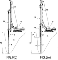
- step (d) the carriage 16 is returned to the upper end 14a of the mast 14 so as to raise the perforation tool 20.
- the shutter 70 is open and concrete B is introduced into the soil through the orifice 28, whereby a lower portion of column C1 is formed.
- the body 40 is held down in the ground on the first depth P1, and does not move.
- the shutter 70 closes when the perforation tool 20 is raised to said first depth P1.
- the perforation tool 20 is pivoted in the direction of rotation a few degrees so that the lug 62 enters the light 64 and comes finally be housed in the housing 68.
- the perforation tool 20 and the body 40 are then secured in rotation and in translation.
- step (e) the perforation tool 20 is raised while driving it in rotation.
- the ballast M is poured into the ground through the opening 50 of the body, above the lower column portion C1, so as to form the upper column portion C2.
- the entire body cavity 40 is filled with the second building material, it is also possible to fill only a part. It is understood that in this case, the upper surface of the second column is located below the surface of the ground.
- the upper portion of the column may also consist of several different materials.
- it may comprise a first section made of ballast and a second section, surmounting the first, made of a less noble material.
- step (e) we obtain the mixed column C represented on the figure 8 , consisting of a lower portion C1 concrete B, and an upper portion C2 ballast M.
- the machine 10 according to the invention also makes it possible to produce mono material columns.
- step (d) the perforation tool 20 is raised while pumping the second construction material - here concrete - into the soil S so as to form the lower portion C1 of the column .
- the concrete may be conveyed by the longitudinal pipe and poured through the orifice 28 located at the lower end 20b of the perforating tool 20.
- step (e) the assembly formed of the body 40 and the perforation tool 20 is completely raised while pumping concrete into the soil S so as to form the upper portion C2 of the column.
- the upper and lower portions are made of concrete, introduced into the ground in a single phase.
- the concrete can again be conveyed by the longitudinal pipe and then discharged through the orifice 28.
- the body 40 could be devoid of spill opening 50.
- the shutter 70 remains open to allow pumping of concrete during this ascent phase. To do this, the lower end of the perforating tool protrudes slightly from the lower end of the body so as not to cause the closing of the shutter.
- the inner wall 46 could also be omitted. According to another example of implementation, it could be provided, on the contrary, that the concrete is conveyed through the body 40, and poured through the opening 50 provided at the lower end of the body.
- the soil to be perforated, very compact makes it difficult for the body 40 to enter the soil S, in particular when the body 40 has a large diameter and the first depth P1 is high.
- a solution according to the invention may consist in carrying out a preliminary step of decompression of the soil S, before making it penetrate the secured assembly of the body 40 and the perforation tool 20 as described in connection with the step (a) above, and continue the implementation with steps (b) through (e).
- This preliminary decompression step consists in descending into the ground, generally at least to the first depth P1, the perforation tool 20 disengaged from the body 40 (remaining, itself, above the surface of the ground), then to reassemble it, before to secure the body 40 and the perforation tool 20.
- FIGS. 9A and 9B illustrate a machine 110 according to a second embodiment of the invention, and particularly suitable for producing two-diameter piles.
- This machine 110 comprises a longitudinal mast 114 fixed to a carrier 112, and a carriage 116 sliding along the mast 114, similar to the carriage 16 of the first embodiment, on which is mounted a first rotational drive system 118 allowing rotating a perforation tool 120.
- the machine 110 further comprises a body 140 similar to the body 40 of the first embodiment.
- the length of the body is here greater than in the case of the realization of a structure with low arase.
- the body here has a length of about 6 meters.
- the machine 110 differs from the previous embodiment in that it further comprises a second carriage 180, slidably mounted along the mast 114, below the first carriage 116.
- this second carriage 180 carries a second rotary drive system 182, coupled to the body 140.
- the second rotary drive system 182 here comprises a ring 184 connected to the outer casing 142 of the body 140, for example by welding on its outer surface.
- the crown is itself connected to a motor 186 rotating it.
- the body 140 being driven in translation by the perforation tool 120, the carriage 180 is here free to translate along the mast 114 being driven by the body 140. No own drive means in translation of the second carriage 180 n is provided on the machine 110.
- the second rotary drive system 182 is intended to act in addition to the perforation tool 120, which, when it is secured to the body 140, drives it into rotation.
- the torque applied to the body 140 during the drilling phase of the soil is thus increased, allowing easier drilling, especially when the body 140 is of large diameter, when the first depth P1 is high, and / or when the ground is particularly compact.
- step (a) the first carriage 116 is disposed at the upper end of the mast 114.
- the perforation tool 120 and the body 140 are in the up position, out of the ground S, and are secured.
- step (b) the perforation tool 120 is rotated and the carriage 116 is lowered towards the lower end of the mast 114, driving the assembly formed by the perforating tool 120 and the body 140 secured together with the second carriage 180 secured to the body 140.
- the second rotating head 182 rotates the body 140 in the same direction as the perforating tool 120.
- the assembly formed by the body 140 and the perforation tool 120 is lowered to the first depth P1.
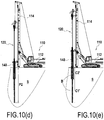
- step (c) the perforation tool 120 and the body 140 are disengaged, and the perforation tool 140 is lowered into the ground S to a second depth P2 greater than the first depth P1.
- step (d) the perforation tool 120 is raised to the depth P1, introducing concrete B into the ground, whereby a lower pile portion is formed, and then the perforation tool 120 and the body 140 are secured (in rotation and in translation).
- step (e) the assembly formed by the perforation tool 120 and the body 140 is finally wound up, while still injecting concrete B through the orifice 128 of the perforating tool, so as to form the portion upper pile.
- an additional step (f) and while the concrete is not yet hardened, to introduce in the first and / or in the second column portion at least one reinforcement cage 190, designed to strengthen the stake.
- at least in the first column portion a first reinforcement cage having a first diameter
- in the second column portion a second reinforcement cage having a larger diameter.
- the second reinforcement cage may possibly surround an upper portion of the first reinforcing cage. It is also possible to have in the first and second column portions a single cage of variable diameter reinforcement.
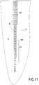
- a two-diameter concrete pile C ' is obtained, as illustrated on FIG. figure 11 , having a lower portion C1 'and an upper portion C2' of greater diameter, reinforced by metal reinforcements.
- the openings 50 and the valves 52 of the body can be omitted.
- the shutter 70 remains open by slightly letting the lower end of the perforation tool out of the body.
- machine according to this second embodiment can be used in the same way for the production of mixed columns, and in particular for the production of low-pitched concrete structures, surmounted by a temporary embankment, as described in FIG. connection with the first embodiment.
Description
- La présente invention concerne le domaine des techniques d'amélioration de sol et celui des fondations profondes.
- De manière générale, les techniques d'amélioration de sol ont pour objectif de consolider des terrains présentant une structure hétérogène, notamment lorsqu'ils sont inconstructibles.
- Parmi ces techniques, il est connu de réaliser un maillage de structures rigides, couramment appelées inclusions rigides, dans le sol. Ces structures sont réalisées pour améliorer la capacité portante du sol et diminuer les tassements.
- La présente invention concerne plus précisément une machine pour la réalisation de structures rigides dans un sol, et un procédé utilisant ladite machine.
- Elle est particulièrement adaptée à la réalisation de telles structures dites à arase basse.
- On parle généralement de structure à arase basse lorsque l'extrémité supérieure d'une structure se trouve à plusieurs mètres sous la plateforme de travail.
- Les techniques connues à ce jour pour la réalisation de telles structures prévoient généralement qu'une colonne continue soit réalisée jusqu'au niveau de la plateforme de travail puis que celle-ci soit recépée jusqu'au niveau de l'arase souhaitée, par exemple à l'aide d'une pelle mécanique lorsque le matériau est encore frais, ou par destruction lorsque le matériau est déjà durci (par exemple au marteau-piqueur, par éclatement, ou par recépage chimique).
- Ces différentes techniques impliquent plusieurs phases de travaux, qui engendrent une augmentation des délais de réalisation. Elles nécessitent par ailleurs la mise en oeuvre de plusieurs outillages différents. Le recépage sur matériau durci présente en outre des problèmes liés à la sécurité et à la santé des opérateurs (bruit et vibration pour l'utilisation des marteaux piqueurs, risque de projection pour les procédés chimiques). Le recépage sur matériau frais implique, lui, de réaliser des excavations de grandes dimensions qui déstructurent le sol et déstabilisent la plateforme de travail.
- On connaît, de la demande de brevet
FR 2 960 571 - Les essais ont montré que cette machine n'est pas adaptée à la réalisation de structures à arase basse, le réservoir ne pouvant pas être introduit dans tous les terrains sur une hauteur suffisante.
- Il a également été constaté à l'utilisation que la vibration du réservoir avait un effet néfaste sur le mât, la somme des vibrations de l'outil de perforation et du réservoir, respectivement en partie haute et basse du mât, fragilisant considérablement la machine.
- Un but de l'invention est de proposer une machine et un procédé de réalisation de structures rigides dans un sol, notamment de structures à arase basse, qui remédient aux inconvénients de l'art antérieur précités.
- Ce but est atteint avec une machine selon l'invention comportant :
- un porteur muni d'un mât s'étendant selon une direction longitudinale ;
- un chariot mobile monté coulissant le long du mât ;
- un outil de perforation de sol, s'étendant selon un axe longitudinal parallèle à ladite direction longitudinale et solidaire dudit chariot mobile, présentant une extrémité supérieure reliée à des moyens d'alimentation en un matériau de construction, et une extrémité inférieure munie d'un orifice pour l'injection du matériau de construction ;
- un système d'entraînement en rotation de l'outil de perforation ; et
- un corps s'étendant autour de l'outil de perforation de sorte que l'outil de perforation est apte à coulisser au travers dudit corps ;
- Dans la présente invention, on comprend que, lorsque le corps est solidarisé à l'outil de perforation, la rotation de l'outil de perforation est transmise directement au corps, qui peut ainsi être introduit facilement dans le sol, et ce, jusqu'à des profondeurs importantes, et quel que soit son diamètre.
- Par ailleurs, le corps étant solidarisé en translation à l'outil de perforation, il n'est pas nécessaire de prévoir des moyens complémentaires de déplacement du corps dans la direction longitudinale du mât. La machine présente donc un nombre de composants limité, ce qui simplifie son montage, et la rend plus facile d'utilisation.
- On comprend que le système de solidarisation est apte, dans une première configuration, à solidariser l'outil de perforation et le corps en rotation autour de l'axe longitudinal dans au moins un sens de rotation et en translation le long de l'axe longitudinal, et, dans une seconde configuration, à libérer lesdits mouvements de rotation et de translation. Un exemple de système de solidarisation pouvant être utilisé est un système à baïonnette.
- L'outil de perforation et le corps peuvent ainsi être introduits ensemble dans le sol à l'état solidarisé, puis peuvent être désolidarisés afin que l'outil de perforation puisse pénétrer dans le sol plus profondément que le corps, en coulissant à travers ce dernier.
- La machine selon l'invention permet ainsi de réaliser dans le sol avec un seul outillage, en une seule phase et avec précision, une colonne comprenant une portion inférieure réalisée grâce à l'outil de perforation, et une portion supérieure réalisée grâce au corps introduit dans le sol.
- On comprend que la forme géométrique de la portion supérieure de la colonne correspond à la forme géométrique (empreinte) du corps. En particulier, la portion supérieure de la colonne présente un diamètre supérieur à celui de la portion inférieure.
- La machine selon l'invention permet par exemple de former des colonnes dites mixtes, dont une portion inférieure est constituée d'un premier matériau de construction et dont une portion supérieure est constituée d'au moins un deuxième matériau de construction différent du premier.
- En l'espèce, le premier matériau est généralement du béton ou du mortier, et le deuxième matériau est généralement un matériau de remplissage tel que du ballast, des granulats, du sable, un remblai liquide, un coulis ou encore un mortier.
- La machine selon l'invention permet donc de réaliser dans le sol des structures rigides surmontées d'un matériau de remplissage pouvant être provisoire (car destiné uniquement à reboucher temporairement le trou de forage formé pour réaliser la structure, et éviter la pollution de la structure) ou destiné à rester en place définitivement notamment pour former un matelas de répartition d'efforts ou une tête de colonne. On comprend que l'arase de la structure se situe alors au niveau de la jonction entre la portion inférieure et la portion supérieure de la colonne. Le niveau de l'arase, qui correspond au niveau de l'extrémité inférieure du corps une fois introduit dans le sol, peut ainsi être déterminé avec précision.
- De façon avantageuse, la machine comprend donc des moyens d'alimentation en un premier matériau de construction reliés à l'extrémité supérieure de l'outil de perforation, et des moyens d'alimentation en au moins un deuxième matériau de construction différent du premier, reliés par exemple à l'extrémité supérieure de l'outil de perforation ou au corps.
- Le corps, entraîné en rotation, peut pénétrer dans le sol jusqu'à une profondeur élevée, y compris lorsqu'il présente un diamètre important. La machine selon l'invention est donc adaptée à la réalisation de structures dites à arase basse. Elle permet en particulier de réaliser une telle structure avec un seul outillage, en une seule phase, et de manière sûre.
- La machine selon l'invention permet aussi, comme il sera décrit dans la suite, de réaliser des colonnes mono-matière, dites colonnes ou pieux bi-diamètre, comprenant une portion inférieure et une portion supérieure de diamètre supérieur à la portion inférieure. Dans ce cas, la portion inférieure et la portion supérieure de colonne sont constituées du même matériau de construction.
- Selon un premier mode de réalisation de l'invention, le corps n'est pas attaché au mât. Plus particulièrement, le corps n'est jamais attaché à l'extrémité inférieure du mât. Il est indépendant du mât. On comprend que, selon ce mode de réalisation, le corps n'est pas relié directement au mât, et qu'il n'est pas non plus relié au mât via un dispositif intermédiaire fixé à l'extrémité inférieure du mât. Le corps est uniquement relié au mât par l'intermédiaire de l'outil de perforation et du système de solidarisation.
- Avec une telle configuration, le mât est préservé d'efforts de vibration qui pourraient l'endommager.
- Selon un deuxième mode de réalisation de l'invention, la machine comprend en outre un deuxième système d'entraînement en rotation, monté sur le mât, configuré pour entraîner le corps en rotation. Le deuxième système d'entraînement en rotation permet d'augmenter le couple de rotation appliqué au corps, ce qui peut être avantageux voire nécessaire, notamment lorsque le corps doit être introduit dans le sol jusqu'à une profondeur élevée.
- Dans le premier mode de réalisation et de préférence également dans le deuxième mode, les moyens pour déplacer le corps dans la direction longitudinale du mât sont formés par l'outil de perforation. Dans le deuxième mode de réalisation, plus particulièrement, le deuxième système d'entraînement en rotation est par exemple monté sur un chariot, lui-même monté libre en translation le long du mât et adapté à être entraîné dans la direction longitudinale du mât par le corps et l'outil de perforation. Autrement dit, il n'existe pas d'autres moyens de déplacement du corps en translation le long du mât, en particulier montés sur le mât.
- L'outil de perforation rotatif est avantageusement du type comprenant une âme centrale s'étendant selon l'axe longitudinal et entourée d'une lame hélicoïdale, formant une tarière. Selon un exemple avantageux, l'outil de perforation est une tarière à refoulement, dont la pénétration dans le sol entraîne un serrage latéral du sol sans vibration ni remontée de déblais le long du forage.
- Le corps comprend généralement une enveloppe externe cylindrique destinée à venir en contact avec le sol et s'étendant autour de l'outil de perforation. On comprend que, lorsque le corps et l'outil de perforation sont solidarisés, la rotation de l'outil de perforation est transmise à l'enveloppe externe du corps, qui tourne alors au contact du sol. Pour faciliter sa pénétration dans le sol, l'enveloppe externe porte par exemple, sur sa face extérieure, une lame hélicoïdale.
- L'enveloppe externe se présente, par exemple, sous la forme d'un tube à section circulaire sensiblement constante.
- Il est parfois souhaitable que la portion de colonne supérieure présente un diamètre sensiblement plus grand que la portion de colonne inférieure. C'est le cas notamment lorsque l'on souhaite réaliser des pieux bi-diamètres.
- Selon un exemple, le diamètre de l'enveloppe externe est au moins 1.2 fois supérieur au diamètre de l'outil de perforation, de préférence au moins 1,5 fois supérieur à ce diamètre.
- Dans la présente demande, on désigne par diamètre de l'enveloppe externe son diamètre extérieur maximal.
- De la même manière, on désigne par diamètre de l'outil de perforation son diamètre extérieur maximal.
- Selon un exemple, le corps comporte en outre une paroi interne disposée entre l'enveloppe externe et l'outil de perforation.
- Dans le cas où l'on souhaite réaliser des colonnes mixtes, le corps peut être destiné à recevoir un deuxième matériau de construction, et peut être muni, à son extrémité inférieure, d'une ouverture pour déverser ledit deuxième matériau.
- L'espace délimité entre l'enveloppe externe et la paroi interne est alors destiné à recevoir le deuxième matériau, avant que celui-ci soit déversé par l'ouverture.
- Selon un exemple, l'outil de perforation comporte en outre un obturateur apte à obturer l'orifice.
- Avantageusement, ledit obturateur est arrangé de telle manière qu'il obture l'orifice lorsque l'extrémité inférieure de l'outil de perforation vient au contact de l'extrémité inférieure du corps.
- L'invention concerne également un procédé de réalisation d'une colonne dans un sol à l'aide d'une machine telle que définie précédemment, dans lequel :
- a) on fait pénétrer dans le sol en les faisant tourner l'outil de perforation et le corps solidarisés en rotation et en translation, jusqu'à une première profondeur prédéterminée ;
- b) on désolidarise le corps et l'outil de perforation ;
- c) on descend l'outil de perforation jusqu'à une deuxième profondeur prédéterminée supérieure à la première ;
- d) on remonte l'outil de perforation depuis ladite deuxième profondeur prédéterminée, tout en introduisant un premier matériau de construction dans le sol au travers de l'orifice situé à l'extrémité inférieure de l'outil de perforation de manière à former la portion inférieure de la colonne, et
- e) on remonte l'outil de perforation et le corps.
- On comprend que lors de l'étape a), on entraîne le déplacement de l'outil de perforation (en rotation et en translation vers la profondeur du sol), en déplaçant le chariot mobile le long du mât et en actionnant le système d'entraînement en rotation de l'outil, et ce déplacement de l'outil de perforation est transmis au corps par l'intermédiaire du système de solidarisation.
- Selon un exemple de mise en oeuvre, le corps est uniquement entraîné en rotation et en translation par l'outil de perforation.
- Selon un autre exemple de mise en oeuvre, la machine comprend un deuxième système d'entraînement en rotation, monté sur le mât, configuré pour entraîner le corps en rotation, et lors de l'étape a), le corps est en outre entraîné en rotation par le deuxième système d'entraînement en rotation.
- Selon un exemple de mise en oeuvre, lors de l'étape e), on déverse dans le sol au moins un deuxième matériau de construction en remontant l'outil de perforation et le corps.
- On comprend que le deuxième matériau de construction peut être différent du premier matériau de construction ou identique à ce dernier.
- Dans le cas où le deuxième matériau de construction est différent du premier, le corps peut être destiné à recevoir le deuxième matériau de construction, et peut être muni, à son extrémité inférieure, d'une ouverture pour déverser ledit deuxième matériau de construction, de sorte qu'au cours de l'étape e), on déverse le deuxième matériau par ladite ouverture.
- Dans le cas où le deuxième matériau de construction est identique au premier matériau de construction, on peut, au cours de l'étape e), déverser le deuxième matériau de construction par l'orifice d'injection de l'outil de perforation.
- Selon un exemple de mise en oeuvre, lors de l'étape d), on remonte l'outil de perforation jusqu'à la première profondeur prédéterminée et on solidarise en rotation le corps et l'outil de perforation ; puis, lors de l'étape e), on remonte l'ensemble formé par le corps et l'outil de perforation en les faisant tourner, tout en déversant dans le sol le deuxième matériau de construction.
- Selon un exemple, le procédé peut comprendre une étape préliminaire a0) réalisée avant l'étape a) et destinée à décomprimer le sol si celui-ci est trop compact, afin de faciliter l'introduction du corps dans le sol. Au cours de cette étape préliminaire, on descend par exemple une première fois l'outil de perforation dans le sol au moins jusqu'à la première profondeur prédéterminée, puis on le remonte.
- Selon un exemple, le procédé comprend une étape postérieure à l'étape e), au cours de laquelle on introduit au moins une cage d'armatures dans la colonne.
- L'invention sera mieux comprise à la lecture de la description détaillée faite ci-après, à titre indicatif mais non limitatif, en référence aux dessins annexés, sur lesquels :
- la
figure 1 représente une machine pour la réalisation de colonnes dans un sol selon un premier mode de réalisation de l'invention ; - la
figure 2 est une vue en perspective, partiellement arrachée, de la partie inférieure de la machine de lafigure 1 ; - les
figures 3A et 3B illustrent le système de solidarisation de l'outil de perforation et du corps ; - les
figures 4 et 5 illustrent le principe de fonctionnement de l'obturateur disposé à l'extrémité inférieure de l'outil de perforation ; - les
figures 6(a) à 6(e) illustrent les différentes étapes du procédé de réalisation d'une colonne, à l'aide de la machine de lafigure 1 ; - la
figure 7 illustre une variante du procédé décrit en liaison avec lafigure 6 ; - la
figure 8 montre une colonne mixte réalisée grâce au procédé selon la présente invention ; - la
figure 9A représente une machine pour la réalisation de colonnes dans un sol selon un deuxième mode de réalisation de l'invention ; - la
figure 9B montre plus en détail le deuxième système d'entraînement en rotation du corps illustré sur lafigure 9A ; - les
figures 10(a) à 10(e) illustrent les différentes étapes du procédé de réalisation d'une colonne, à l'aide de la machine de lafigure 9A ; - la
figure 11 illustre un pieu bi-diamètre réalisé grâce au procédé selon la présente invention. - Sur la
figure 1 on a représenté une machine 10 pour la réalisation de colonnes dans un sol S selon un premier mode de réalisation de l'invention. - La machine de forage 10 comprend un porteur 12 sur lequel est monté, généralement de façon articulée, un mât de forage 14. Sur le porteur 12 peuvent également être montés d'autres équipements tels que le pupitre de commande de la machine de forage 10.
- Un chariot mobile 16 est monté coulissant le long du mât 14. Ce chariot coulissant 16 peut être déplacé le long du mât 14 par des moyens connus par ailleurs et non détaillés ici.
- Un dispositif d'entraînement en rotation (premier dispositif d'entraînement en rotation) sous la forme d'une tête de rotation 18, est monté sur le chariot 16. La tête de rotation 18 est reliée à l'extrémité supérieure d'un outil de perforation 20, qu'elle est adaptée à mettre en rotation pour réaliser la perforation du sol S.
- Pour la suite, on définit une extrémité inférieure 20b de l'outil de perforation 20 dirigée vers le sol en position prêt à forer, et une extrémité supérieure 20a dudit outil, dirigée vers le ciel dans la même position.
- L'outil de perforation 20 comprend une âme centrale creuse 22 s'étendant selon un axe longitudinal X parallèle au mât 14 et délimitant une conduite longitudinale, ainsi qu'un outil de coupe 26 à son extrémité inférieure, permettant le découpage du sol S.
- Dans l'exemple particulier illustré, l'outil de perforation 20 est une tarière, et plus particulièrement une tarière à refoulement, adaptée pour perforer le sol sans extraction de déblais. Cet exemple n'est cependant pas limitatif.
- Le fonctionnement d'une tarière à refoulement est bien connu en soi, et n'est donc pas décrit en détail dans la suite.
- On retient simplement ici que l'outil de perforation 20 comporte une lame hélicoïdale 24, de diamètre sensiblement constant, s'étendant sur une portion inférieure 30 de l'âme centrale 22 (voir en particulier la
figure 3A ). Dans l'exemple, la portion inférieure 30 est surmontée d'une portion supérieure 32 de diamètre plus élevé, destinée à refouler latéralement le sol découpé par la lame hélicoïdale 24, lors du forage. - L'extrémité supérieure 20a de l'outil de perforation 20 est reliée à des moyens d'alimentation 34 en un premier matériau de construction, en l'espèce du béton.
- L'extrémité inférieure 20b de l'outil de perforation 20 est quant à elle munie d'un orifice 28 pour l'injection du premier matériau de construction dans le sol S.
- Selon l'invention, la machine 10 comporte en outre un corps 40, formant ici réservoir, s'étendant autour de l'outil de perforation 20.
- Comme il ressort particulièrement des
figures 2 et3 , le corps 40 comporte une enveloppe externe cylindrique 42 destinée à venir en contact avec le sol S et s'étendant autour de l'outil de perforation 20. - L'enveloppe externe 42 du corps 40 est coaxiale à l'outil de perforation 20 et porte, sur sa face externe, une lame hélicoïdale 44, destinée à faciliter la pénétration, par rotation, du corps 40 dans le sol.
- Le diamètre de l'enveloppe externe 42 est généralement au moins 1,2 fois supérieur au diamètre de l'outil de perforation 20.
- A titre d'exemple, le diamètre de l'enveloppe externe est de 600 mm, pour un diamètre de l'outil de perforation égal à 420 mm.
- Dans l'exemple, le corps 40 est destiné à recevoir un deuxième matériau de construction et comporte pour cela une paroi interne 46 sous la forme d'un tube, disposée à l'intérieur de l'enveloppe externe 42 et définissant avec elle un espace annulaire 48 destiné à recevoir ledit deuxième matériau, en l'espèce du ballast. On comprend que l'espace annulaire 48 s'étend radialement entre le tube interne 46 et l'enveloppe externe 42.
- Le corps 40 est muni, à son extrémité inférieure, d'au moins une ouverture (en l'espèce deux) 50 pour déverser le deuxième matériau de construction.
- Dans l'exemple, l'extrémité inférieure du corps comporte en outre au moins un clapet (en l'espèce deux) 52 dimensionné pour pouvoir recouvrir l'ouverture 50 du corps. Autrement dit, chaque clapet 52 est destiné à boucher une ouverture 50.
- En l'espèce, chaque clapet 52 est monté pivotant autour d'un axe 54 monté sur l'enveloppe externe 42. Dans l'exemple, chaque clapet est configuré pour se fermer lors de la descente du corps 40 du fait de son appui contre le sol et pour s'ouvrir gravitairement lors de la remontée sous l'effet de la poussée du deuxième matériau déversé par l'ouverture correspondante 50.
- Dans l'exemple illustré, l'extrémité supérieure de l'enveloppe externe 42 est en outre solidaire d'une portion formant entonnoir 56 qui permet de faciliter le remplissage du corps 40 avec le deuxième matériau de construction.
- Dans le mode de réalisation illustré, le déplacement du corps 40 se fait exclusivement par l'intermédiaire de l'outil de perforation 20. Le corps 40 n'est pas monté sur le mât 14 de la machine 10. Il est indépendant du mât 14.
- La machine 10 est équipée d'un système de solidarisation 60 pour permettre la solidarisation du corps 40 avec l'outil de perforation 20, en rotation et en translation. Ces moyens de solidarisation 60, dont le principe de fonctionnement se comprend mieux à l'aide des
figures 3A et 3B , comprennent en l'espèce au moins un premier élément fixé à ou formant partie intégrante de l'outil de perforation 20 et au moins un second élément fixé à ou formant partie intégrante du corps 40, lesdits éléments étant adaptés à coopérer pour former une liaison à baïonnette. - Dans l'exemple, le premier élément est un ergot 62 formé à la périphérie de l'âme centrale 22. Plus particulièrement, l'outil de perforation 20 présente ici deux ergots, diamétralement opposés.
- Le deuxième élément est une lumière en L 64 formée dans une partie supérieure du corps 40, dont une première branche 66, ouverte à son extrémité inférieure, s'étend selon la direction longitudinale, et l'autre 68 forme un logement s'étendant orthogonalement à ladite première branche 66, dans la direction F1 de rotation du corps 40. Plus particulièrement, le corps présente ici deux lumières 64, diamétralement opposés.
- A noter que les moyens de solidarisation 60 peuvent aussi prendre une forme différente. Selon une variante, notamment, le au moins un premier élément peut être une lumière et le au moins un deuxième élément peut être un ergot.
- Dans l'exemple illustré, on comprend aisément que dans une première position (position couplée) dans laquelle chaque ergot 62 vient en butée contre la paroi de fond 68c d'un logement 68 (ergot illustré en pointillé sur la
figure 3B ), l'outil de perforation 20 entraîne le corps 40 dans son mouvement lorsqu'il est mis en rotation autour de son axe X dans le sens F1. - Lorsque, dans le même temps, l'outil de perforation est déplacé vers l'aval, c'est-à-dire vers le sol, chaque ergot 62 vient en butée contre la paroi amont 68b du logement 68. En conséquence, l'outil de perforation 20 entraîne le corps 40 dans son mouvement de translation.
- A l'inverse, dans une deuxième position (position découplée) dans laquelle chaque ergot 62 est extrait du logement 68 (ergot illustré en plein sur la
figure 3B ), l'âme centrale 22 est entièrement libre de coulisser à travers le corps 40 et libre de tourner relativement au corps 40. Elle peut alors, comme il sera décrit plus en détail dans la suite, être descendue dans le sol S jusqu'à la profondeur P2 désirée pour la colonne, puis remonter jusqu'au corps en déversant le premier matériau de construction par son orifice 28. - On note que, dans l'exemple, les lumières 64 sont formées dans une partie supérieure du corps 40 configurée de sorte que, quelle que soit la position angulaire de l'âme centrale 20 par rapport au corps 40, les ergots 62 viennent en butée contre ladite portion dans leur position la plus haute. On comprend qu'ainsi, l'outil de perforation 20 entraîne toujours le corps 40 dans son mouvement de remontée le long de l'axe X, les ergots venant en butée contre le corps 40.
- La portion supérieure dont il est question est ici une portion supérieure du tube interne 46, de diamètre interne réduit.
- A noter que, dans le mouvement de remontée précité, on souhaite stopper le déversement du béton une fois l'extrémité inférieure 20b de l'outil arrivée au contact de l'extrémité inférieure 40b du corps 40.
- Pour ce faire, et comme illustré plus en détail sur les
figures 4 et 5 , un obturateur 70 est monté pivotant à l'extrémité inférieure 20b de l'outil de perforation 20, autour d'un axe de rotation 74. Plus précisément, l'obturateur 70 présente une surface de butée 72 adaptée, lorsque l'outil de perforation 20 est remonté à proximité du corps 40, à coopérer avec l'extrémité inférieure du tube interne 46 selon un mécanisme de came, pour provoquer la rotation de l'obturateur 70 autour de l'axe 74 à la suite de quoi ce dernier vient obturer l'orifice 28. Ainsi, l'écoulement du béton est stoppé. - A l'aide des
figures 6(a) à 6(e) , on va maintenant décrire un exemple du procédé de réalisation d'une colonne mixte C dans un sol S selon l'invention à l'aide de la machine 10 que l'on vient de décrire. - A l'étape (a), le chariot 16 est positionné en haut du mât 14, de sorte que le corps 40 et l'outil de perforation 20, solidarisés, sont disposés hors du sol.
- A l'étape (b), la tête de rotation 18 est actionnée et le chariot 16 est déplacé vers l'extrémité inférieure du mât 14 de sorte que le corps 40 et l'outil de perforation 20 pénètrent dans le sol S jusqu'à une première profondeur prédéterminée P1. Le corps 40 et l'outil de perforation 20 sont solidairement entraînés en rotation dans le sens de la flèche F1.
- A l'étape (c), l'outil de perforation 20 est pivoté en sens inverse de quelques degrés, de manière à extraire l'ergot 62 du logement 68 et le placer au droit de la deuxième branche 66 de la lumière 64. Le corps 40 reste lui en place, et en particulier ne tourne pas, du fait du frottement du sol S contre son enveloppe externe 42. Le corps 40 et l'outil de perforation 20 sont alors dans leur position découplée.
- Le chariot 16 est alors déplacé le long du mât 14, vers son extrémité inférieure 14b, entraînant la descente de l'outil de perforation 40 dans le sol S jusqu'à une deuxième profondeur P2 supérieure à la première profondeur P1.
- A l'étape (d), le chariot 16 est ramené vers l'extrémité supérieure 14a du mât 14 de manière à remonter l'outil de perforation 20. Pendant la remontée, l'obturateur 70 est ouvert et du béton B est introduit dans le sol au travers de l'orifice 28, grâce à quoi une portion inférieure de colonne C1 est formée. Dans cette étape, le corps 40 est maintenu enfoncé dans le sol sur la première profondeur P1, et ne bouge pas. Comme on l'a vu précédemment, l'obturateur 70 se referme lorsque l'outil de perforation 20 est remonté jusqu'à ladite première profondeur P1. A cet instant, l'outil de perforation 20 est pivoté dans le sens de rotation de quelques degrés de façon à ce que l'ergot 62 pénètre dans la lumière 64 et vienne finalement se loger dans le logement 68. L'outil de perforation 20 et le corps 40 sont alors solidarisés en rotation et en translation.
- A l'étape (e), on remonte l'outil de perforation 20, tout en l'entraînant en rotation. Au cours de la remontée du corps 40, du ballast M est déversé dans le sol au travers de l'ouverture 50 du corps, au-dessus de la portion de colonne inférieure C1, de manière à former la portion de colonne supérieure C2.
- A noter que bien que dans l'exemple illustré, toute l'empreinte du corps 40 est remplie du second matériau de construction, il est également possible de n'en remplir qu'une partie. On comprend que dans ce cas, la surface supérieure de la deuxième colonne est située en-dessous de la surface du sol.
- A noter également que la portion supérieure de colonne peut aussi être constituée de plusieurs matériaux différents. Par exemple, elle peut comprendre un premier tronçon réalisé en ballast et un deuxième tronçon, surmontant le premier, réalisé dans un matériau moins noble.
- Dans l'exemple, à l'issue de l'étape (e), on obtient la colonne mixte C représentée sur la
figure 8 , constituée d'une portion inférieure C1 en béton B, et d'une portion supérieure C2 en ballast M. - La machine 10 selon l'invention permet également de réaliser des colonnes mono matière. Pour ce faire, au cours de l'étape (d), on remonte l'outil de perforation 20 tout en pompant le deuxième matériau de construction - ici du béton - dans le sol S de manière à former la portion inférieure C1 de la colonne. Le béton peut être acheminé par la conduite longitudinale et déversé par l'orifice 28 situé à l'extrémité inférieure 20b de l'outil de perforation 20.
- Puis, au cours de l'étape (e), on remonte complètement l'ensemble formé du corps 40 et de l'outil de perforation 20, tout en pompant du béton dans le sol S de manière à former la portion supérieure C2 de la colonne. On comprend que, dans cet exemple de réalisation, les portions supérieure et inférieure sont constituées de béton, introduit dans le sol en une seule phase. Le béton peut là encore être acheminé par la conduite longitudinale puis déversé par l'orifice 28. On comprend que, dans cette utilisation particulière, le corps 40 pourrait être dépourvu d'ouverture de déversement 50. Dans cas, on prévoit que l'obturateur 70 reste ouvert pour permettre le pompage du béton pendant cette phase de remontée. Pour ce faire, l'extrémité inférieure de l'outil de perforation dépasse légèrement de l'extrémité inférieure du corps afin de ne pas provoquer la fermeture de l'obturateur.
- Selon une disposition particulière, la paroi interne 46 pourrait, elle aussi, être omise. Selon un autre exemple de mise en oeuvre, on pourrait prévoir, au contraire, que le béton soit acheminé par l'intermédiaire du corps 40, et déversé par l'ouverture 50 prévue à l'extrémité inférieure du corps.
- Dans certains cas de figure, le sol à perforer, très compact, rend difficile la pénétration du corps 40 dans le sol S, en particulier lorsque le corps 40 présente un grand diamètre et que la première profondeur P1 est élevée.
- Dans ce cas, une solution selon l'invention peut consister à réaliser une étape préalable de décompression du sol S, avant d'y faire pénétrer l'ensemble solidarisé du corps 40 et de l'outil de perforation 20 comme décrit en liaison avec l'étape (a) ci-dessus, et de poursuivre la mise en oeuvre avec les étapes (b) à (e).
- Cette étape préalable de décompression, illustrée par la
figure 7 , consiste à descendre dans le sol, généralement au moins jusqu'à la première profondeur P1, l'outil de perforation 20 désolidarisé du corps 40 (restant, lui, au-dessus de la surface du sol), puis à le remonter, avant de solidariser le corps 40 et l'outil de perforation 20. - Les
figures 9A et 9B illustrent une machine 110 conforme à un deuxième mode de réalisation de l'invention, et particulièrement adaptée à la réalisation de pieux bi-diamètres. - A noter que les éléments identiques ou similaires à ceux de la machine 10 du premier mode de réalisation y portent les mêmes références numériques incrémentées de 100.
- Cette machine 110 comporte un mât longitudinal 114 fixé à un porteur 112, et un chariot 116 coulissant le long du mât 114, similaire au chariot 16 du premier mode de réalisation, sur lequel est monté un premier système d'entraînement en rotation 118 permettant d'entraîner en rotation un outil de perforation 120.
- La machine 110 comprend par ailleurs un corps 140 similaire au corps 40 du premier mode de réalisation. On note néanmoins que la longueur du corps est ici plus grande que dans le cas de la réalisation d'une structure à arase basse. Le corps présente ici une longueur de l'ordre de 6 mètres.
- Un système de solidarisation 160 entre le corps 140 et l'outil de perforation 120, similaire à celui du premier mode de réalisation, est également prévu.
- La machine 110 selon ce deuxième mode de réalisation se différencie de la précédente en ce qu'elle comporte en outre un deuxième chariot 180, monté coulissant le long du mât 114, en dessous du premier chariot 116.
- Dans l'exemple illustré, ce deuxième chariot 180 porte un deuxième système d'entraînement en rotation 182, couplé au corps 140.
- Le deuxième système d'entraînement en rotation 182 comprend ici une couronne 184 reliée à l'enveloppe externe 142 du corps 140, par exemple par soudure sur sa surface extérieure. La couronne est elle-même reliée à un moteur 186 l'entraînant en rotation.
- Le corps 140 étant entraîné en translation par l'outil de perforation 120, le chariot 180 est ici libre de se translater le long du mât 114 en étant entraîné par le corps 140. Aucun moyen propre d'entraînement en translation du deuxième chariot 180 n'est prévu sur la machine 110.
- On comprend que le deuxième système d'entraînement en rotation 182 est destiné à agir en complément de l'outil de perforation 120, qui, lorsqu'il est solidarisé au corps 140, l'entraîne en rotation. Le couple de rotation appliqué au corps 140 lors de la phase de forage du sol est ainsi augmenté, permettant un forage plus aisé, notamment lorsque le corps 140 est de diamètre important, lorsque la première profondeur P1 est élevée, et/ou lorsque le sol est particulièrement compact.
- A l'aide des
figures 10(a) à 10(e) , on va maintenant décrire un procédé selon l'invention de réalisation d'un pieu bi-diamètre à l'aide de la machine 110 du deuxième mode de réalisation illustré sur lesfigures 9A et 9B . - A l'étape (a), le premier chariot 116 est disposé à l'extrémité supérieure du mât 114. L'outil de perforation 120 et le corps 140 se trouvent en position haute, hors du sol S, et sont solidarisés.
- A l'étape (b), l'outil de perforation 120 est entrainé en rotation et le chariot 116 est descendu vers l'extrémité inférieure du mât 114, entraînant l'ensemble formé par l'outil de perforation 120 et le corps 140 solidarisés, ainsi que le deuxième chariot 180, solidaire du corps 140. Dans le même temps, la deuxième tête de rotation 182 entraîne en rotation le corps 140, dans le même sens que l'outil de perforation 120.
- L'ensemble formé par le corps 140 et l'outil de perforation 120 est descendu jusqu'à la première profondeur P1.
- A l'étape (c), l'outil de perforation 120 et le corps 140 sont désolidarisés, et l'outil de perforation 140 est descendu dans le sol S jusqu'à une deuxième profondeur P2 supérieure à la première profondeur P1.
- A l'étape (d), l'outil de perforation 120 est remonté jusqu'à la profondeur P1, en introduisant du béton B dans le sol, grâce à quoi une portion inférieure de pieu est formée, puis l'outil de perforation 120 et le corps 140 sont solidarisés (en rotation et en translation).
- A l'étape (e), on remonte finalement l'ensemble formé par l'outil de perforation 120 et le corps 140, en injectant toujours du béton B par l'orifice 128 de l'outil de perforation, afin de former la portion supérieure du pieu.
- De manière optionnelle on peut, dans une étape supplémentaire (f), et alors que le béton n'est pas encore durci, introduire dans la première et/ou dans la deuxième portion de colonne au moins une cage d'armatures 190, destinée à renforcer le pieu. Par exemple, on peut disposer au moins dans la première portion de colonne une première cage d'armatures présentant un premier diamètre, et, dans la deuxième portion de colonne, une seconde cage d'armatures de diamètre plus élevé. Dans ce cas, la deuxième cage d'armatures peut éventuellement entourer une partie supérieure de la première cage d'armatures. On peut aussi disposer dans la première et la deuxième portion de colonne une unique cage d'armatures à diamètre variable.
- Après durcissement du béton, on obtient finalement un pieu bi-diamètre en béton C' tel qu'illustré sur la
figure 11 , présentant une portion inférieure C1' et une portion supérieure C2' de diamètre plus élevé, renforcées par des armatures métalliques. - On comprend que dans ce deuxième mode de réalisation, les ouvertures 50 et les clapets 52 du corps peuvent être omis. Dans ce cas, on prévoit également que l'obturateur 70 reste ouvert en laissant dépasser légèrement l'extrémité inférieure de l'outil de perforation hors du corps.
- A noter cependant que la machine selon ce deuxième mode de réalisation peut être utilisée de la même manière pour la réalisation de colonnes mixtes, et en particulier pour la réalisation de structures en béton à arase basse, surmontée d'un remblai provisoire, comme décrit en liaison avec le premier mode de réalisation.
Claims (18)
- Machine (10, 110) pour la réalisation de colonnes dans un sol (S), comportant :- un porteur (12,112) muni d'un mât (14, 114) s'étendant selon une direction longitudinale ;- un chariot mobile (16, 116) monté coulissant le long du mât (14, 114) ;- un outil de perforation de sol (20, 120), s'étendant selon un axe longitudinal (X) parallèle à ladite direction longitudinale et solidaire dudit chariot mobile, présentant une extrémité supérieure (20a, 120a) reliée à des moyens d'alimentation en un matériau de construction, et une extrémité inférieure munie d'un orifice (28, 128) pour l'injection du matériau de construction ;- un système d'entraînement en rotation de l'outil de perforation (18, 118) ; et- un corps (40, 140) s'étendant autour de l'outil de perforation (20, 120) de sorte que l'outil de perforation est apte à coulisser au travers dudit corps ;ladite machine étant caractérisée en ce qu'elle comprend en outre un système de solidarisation (60, 160) du corps (40, 140) avec l'outil de perforation (20, 120), configuré de sorte que, dans au moins une configuration, la rotation de l'outil de perforation (20, 120) entraîne la rotation du corps (40, 140) et la translation de l'outil de perforation (20, 120) entraîne la translation du corps (40, 140).
- Machine (10, 110) selon la revendication 1, dans laquelle le système de solidarisation (60, 160) est un système à baïonnette.
- Machine (10) selon la revendication 1 ou 2, dans laquelle le corps (40) n'est pas attaché au mât (14).
- Machine (110) selon la revendication 1 ou 2, comprenant en outre un deuxième système d'entraînement en rotation (182), monté sur le mât (14, 114), configuré pour entraîner le corps (140) en rotation.
- Machine (10, 110) selon l'une quelconque des revendications 1 à 4, dans laquelle l'outil de perforation (20, 120) comprend une âme centrale (22, 122) s'étendant selon l'axe longitudinal (X) et entourée d'une lame hélicoïdale (24, 124).
- Machine (10, 110) selon l'une quelconque des revendications 1 à 5, dans laquelle le corps (40, 140) comprend une enveloppe externe cylindrique (42, 142) destinée à venir en contact avec le sol et s'étendant autour de l'outil de perforation (20, 120).
- Machine (10, 110) selon la revendication 6, dans laquelle le diamètre de l'enveloppe externe (42, 142) est au moins 1,2 fois supérieur au diamètre de l'outil de perforation (20, 120), de préférence au moins 1,5 fois supérieur à ce diamètre.
- Machine (10, 110) selon la revendication 6 ou 7, dans laquelle l'enveloppe externe (42, 142) porte une lame hélicoïdale (44, 144) sur sa face externe.
- Machine (10, 110) selon l'une quelconque des revendications 6 à 8, dans laquelle le corps (40, 140) comporte en outre une paroi interne (46, 146) disposée entre l'enveloppe externe (42) et l'outil de perforation (20, 120).
- Machine (10) selon l'une quelconque des revendications 1 à 9, dans laquelle le corps (40) est destiné à recevoir un deuxième matériau de construction, et est muni, à son extrémité inférieure, d'une ouverture (50) pour déverser ledit deuxième matériau de construction.
- Machine (10, 110) selon l'une quelconque des revendications 1 à 10, dans laquelle l'outil de perforation (20, 120) comporte en outre un obturateur (70) apte à obturer l'orifice (28, 128).
- Machine selon la revendication 11, dans laquelle ledit obturateur (70) est arrangé de telle manière qu'il obture l'orifice lorsque l'extrémité inférieure de l'outil de perforation (20, 120) vient au contact de l'extrémité inférieure du corps (40, 140).
- Procédé de réalisation d'une colonne dans un sol à l'aide d'une machine selon l'une quelconque des revendications 1 à 12, dans lequel :a) on fait pénétrer dans le sol en les faisant tourner l'outil de perforation (20, 120) et le corps (40, 140) solidarisés en rotation et en translation, jusqu'à une première profondeur prédéterminée (P1) ;b) on désolidarise le corps (40, 140) et l'outil de perforation (20, 120) ;c) on descend l'outil de perforation (20, 120) jusqu'à une deuxième profondeur prédéterminée (P2) supérieure à la première (P1) ;d) on remonte l'outil de perforation (20, 120) depuis ladite deuxième profondeur prédéterminée (P2), tout en introduisant un premier matériau de construction dans le sol au travers de l'orifice (28, 128) situé à l'extrémité inférieure de l'outil de perforation (20, 120) ; ete) on remonte l'outil de perforation (20, 120) et le corps (40, 140).
- Procédé selon la revendication 13, dans lequel, lors de l'étape e), on déverse dans le sol au moins un deuxième matériau de construction en remontant l'outil de perforation (20, 120) et le corps (40, 140).
- Procédé selon la revendication 14, dans lequel au cours de l'étape e), on déverse ledit au moins un deuxième matériau de construction par l'orifice (28, 128) de l'outil de perforation (20, 120).
- Procédé selon la revendication 14 ou 15, dans lequel le corps (40, 140) est destiné à recevoir le au moins un deuxième matériau de construction, et est muni, à son extrémité inférieure, d'une ouverture (50, 150) pour déverser ledit deuxième matériau de construction, et au cours de l'étape e), on déverse le deuxième matériau par ladite ouverture (50, 150).
- Procédé selon l'une quelconque des revendications 13 à 16, comprenant préalablement à l'étape a) une étape a0) dans laquelle on descend une première fois l'outil de perforation (20, 120) dans le sol au moins jusqu'à la première profondeur prédéterminée (P1), puis on le remonte.
- Procédé selon l'une quelconque des revendications 13 à 17, dans lequel la machine comprend un deuxième système d'entraînement en rotation (182), monté sur le mât (14, 114), configuré pour entraîner le corps (140) en rotation, et lors de l'étape a), le corps est entraîné en rotation par le premier système d'entraînement en rotation (18, 118) et le deuxième système d'entraînement en rotation (182).
Priority Applications (1)
| Application Number | Priority Date | Filing Date | Title |
|---|---|---|---|
| PL15187924T PL3002371T3 (pl) | 2014-10-01 | 2015-10-01 | Maszyna i sposób dla wykonywania kolumn w gruncie |
Applications Claiming Priority (1)
| Application Number | Priority Date | Filing Date | Title |
|---|---|---|---|
| FR1459355A FR3026754B1 (fr) | 2014-10-01 | 2014-10-01 | Machine et procede pour la realisation de colonnes dans un sol |
Publications (2)
| Publication Number | Publication Date |
|---|---|
| EP3002371A1 EP3002371A1 (fr) | 2016-04-06 |
| EP3002371B1 true EP3002371B1 (fr) | 2017-06-28 |
Family
ID=51866273
Family Applications (1)
| Application Number | Title | Priority Date | Filing Date |
|---|---|---|---|
| EP15187924.4A Active EP3002371B1 (fr) | 2014-10-01 | 2015-10-01 | Machine et procédé pour la réalisation de colonnes dans un sol |
Country Status (6)
| Country | Link |
|---|---|
| US (1) | US9624638B2 (fr) |
| EP (1) | EP3002371B1 (fr) |
| CA (1) | CA2906244C (fr) |
| FR (1) | FR3026754B1 (fr) |
| HU (1) | HUE034523T2 (fr) |
| PL (1) | PL3002371T3 (fr) |
Families Citing this family (28)
| Publication number | Priority date | Publication date | Assignee | Title |
|---|---|---|---|---|
| US9512588B2 (en) | 2014-10-17 | 2016-12-06 | Berkel & Company Contractors, Inc. | Reversible displacement auger tool |
| US9506295B1 (en) | 2014-10-17 | 2016-11-29 | Berkel & Company Contractors, Inc. | Reversible displacement auger tool |
| ITUB20159641A1 (it) * | 2015-12-18 | 2017-06-18 | Soilmec Spa | Dispositivo e metodo per la movimentazione e l?assemblaggio reciproco di segmenti di una batteria di scavo, per esempio segmenti di elica o di asta. |
| FR3078739B1 (fr) * | 2018-03-09 | 2020-03-27 | Soletanche Freyssinet | Machine de forage comportant un dispositif de connexion pour un dispositif de mesure de verticalite |
| US10889955B2 (en) | 2018-07-30 | 2021-01-12 | Schnabel Foundation Company | Cutting tool adapter and method of underpinning structures using cutting tool adapter for soil mixing |
| US11479938B2 (en) * | 2019-03-29 | 2022-10-25 | Ojjo, Inc. | Systems, methods and machines for aligning and assembling truss foundations |
| RO134509A1 (ro) * | 2019-04-08 | 2020-10-30 | Tudor Saidel | Procedeu şi dispozitiv de execuţie pe loc a unui pilot, cu diametre diferite, descrescătoare în adâncime |
| FR3097588B1 (fr) * | 2019-06-21 | 2022-03-18 | Soletanche Freyssinet | Machine pour forer un sol recouvert d’une couche poreuse, et procédé correspondant |
| CN110374097A (zh) * | 2019-07-26 | 2019-10-25 | 北京中岩大地科技股份有限公司 | 基于大直径搅拌提高桩基承载力的施工方法 |
| US11051795B2 (en) | 2019-07-31 | 2021-07-06 | Covidien Lp | Tissue retrieval bag |
| US11304687B2 (en) | 2019-08-13 | 2022-04-19 | Covidien Lp | Tissue specimen bag furling device and method |
| US11253240B2 (en) | 2019-09-10 | 2022-02-22 | Covidien Lp | Tissue specimen retrieval devices |
| US11172949B2 (en) | 2019-10-07 | 2021-11-16 | Covidien Lp | Tissue specimen retrieval devices |
| US11168456B2 (en) | 2019-11-08 | 2021-11-09 | Ojjo, Inc. | Systems, methods, and machines for automated screw anchor driving |
| US11759188B2 (en) | 2020-01-31 | 2023-09-19 | Covidien Lp | Devices, systems, and methods for specimen removal |
| US11160543B2 (en) | 2020-02-13 | 2021-11-02 | Covidien Lp | Magnetic suture tab for free standing specimen bag |
| US11224413B2 (en) | 2020-02-19 | 2022-01-18 | Covidien Lp | Retrieval device with bag release mechanism |
| US11369352B2 (en) | 2020-03-31 | 2022-06-28 | Covidien Lp | Dual channel design for free standing specimen bag |
| US11406369B2 (en) | 2020-04-08 | 2022-08-09 | Covidien Lp | Tissue specimen retrieval device with reinforced spring |
| WO2021211065A1 (fr) * | 2020-04-13 | 2021-10-21 | Seafco Public Company Limited | Système et procédé d'installation de pieux |
| US11246613B2 (en) | 2020-05-15 | 2022-02-15 | Covidien Lp | Actuation mechanisms for tissue specimen retrieval devices and tissue specimen retrieval devices incorporating the same |
| US11304714B2 (en) | 2020-05-19 | 2022-04-19 | Covidien Lp | Tissue specimen retrieval device with assisted deployment |
| US11517297B2 (en) | 2020-06-05 | 2022-12-06 | Covidien Lp | Rollable tissue specimen bag with improved brim for tenting |
| EP4080012A1 (fr) * | 2021-04-22 | 2022-10-26 | ABI Anlagentechnik-Baumaschinen-Industriebedarf Maschinenfabrik und Vertriebsgesellschaft mbH | Machine de construction pour le génie civil spécial |
| EP4098803A1 (fr) * | 2021-05-31 | 2022-12-07 | ABI Anlagentechnik-Baumaschinen-Industriebedarf Maschinenfabrik und Vertriebsgesellschaft mbH | Lance de bourrage vibrante et procédé d'équipement d'un mât d'une lance de bourrage vibrante |
| CN114482027A (zh) * | 2022-03-07 | 2022-05-13 | 中部城市建设有限公司 | 一种混凝土桩身载体桩的施工方法 |
| CN114753370B (zh) * | 2022-03-23 | 2023-12-15 | 郓城县水务局 | 一种水利工程施工用物料灌浆装置及其使用方法 |
| CN115450217A (zh) * | 2022-09-06 | 2022-12-09 | 中国水电基础局有限公司 | 一种在孔口预埋管内开孔破壁灌浆的灌浆方法 |
Family Cites Families (9)
| Publication number | Priority date | Publication date | Assignee | Title |
|---|---|---|---|---|
| US3604214A (en) * | 1968-08-16 | 1971-09-14 | Lee A Turzillo | Means and method of making columnar structures in situ |
| US3512366A (en) * | 1969-02-14 | 1970-05-19 | Lee A Turzillo | Method for forming cast-in-place reinforced concrete pile |
| US3690109A (en) * | 1970-03-16 | 1972-09-12 | Lee A Turzillo | Method and means for producing pile or like structural columns in situ |
| US3886754A (en) * | 1973-07-27 | 1975-06-03 | Lee A Turzillo | Method of extending augered pile cavity through rock or like obstruction |
| JPS61207712A (ja) * | 1985-03-12 | 1986-09-16 | N I T:Kk | 地盤改良工法及びその装置 |
| US6183166B1 (en) * | 1999-04-01 | 2001-02-06 | Verne L. Schellhorn | Method of centrifugally forming a subterranean soil-cement casing |
| DE10238193B4 (de) * | 2002-08-21 | 2004-08-19 | Bauer Spezialtiefbau Gmbh | Bohrvorrichtung |
| FR2903711B1 (fr) * | 2006-07-12 | 2010-12-10 | Cie Du Sol | Outil melangeur pour le traitement d'une portion de sol. |
| FR2960571B1 (fr) * | 2010-05-27 | 2012-06-22 | Soletanche Freyssinet | Machine et procede pour la realisation de colonnes dans un sol |
-
2014
- 2014-10-01 FR FR1459355A patent/FR3026754B1/fr active Active
-
2015
- 2015-09-25 CA CA2906244A patent/CA2906244C/fr active Active
- 2015-09-29 US US14/868,504 patent/US9624638B2/en active Active
- 2015-10-01 EP EP15187924.4A patent/EP3002371B1/fr active Active
- 2015-10-01 PL PL15187924T patent/PL3002371T3/pl unknown
- 2015-10-01 HU HUE15187924A patent/HUE034523T2/en unknown
Non-Patent Citations (1)
| Title |
|---|
| None * |
Also Published As
| Publication number | Publication date |
|---|---|
| FR3026754B1 (fr) | 2016-12-02 |
| CA2906244C (fr) | 2023-01-03 |
| PL3002371T3 (pl) | 2017-12-29 |
| EP3002371A1 (fr) | 2016-04-06 |
| US9624638B2 (en) | 2017-04-18 |
| HUE034523T2 (en) | 2018-02-28 |
| CA2906244A1 (fr) | 2016-04-01 |
| US20160097177A1 (en) | 2016-04-07 |
| FR3026754A1 (fr) | 2016-04-08 |
Similar Documents
| Publication | Publication Date | Title |
|---|---|---|
| EP3002371B1 (fr) | Machine et procédé pour la réalisation de colonnes dans un sol | |
| EP0265344B1 (fr) | Procédé pour la réalisation d'un pieu dans le sol, machine de forage et dispositif pour la mise en oeuvre de ce procédé | |
| EP1525371A1 (fr) | Conduite de guidage telescopique de forage en mer | |
| FR2503241A1 (fr) | Dispositif a trepan pouvant etre descendu dans un puits de forage progressant dans un terrain dur, notamment du rocher, et procede pour le forage | |
| EP2156907B1 (fr) | Equipement et procédé de traitement de polluants dans le sol | |
| EP2390419B1 (fr) | Machine et procédé pour la réalisation de colonnes dans le sol | |
| FR2566813A1 (fr) | Dispositif et procede pour la realisation de pieux en beton dans le sol et pieux obtenus par ce procede | |
| EP0382607B1 (fr) | Dispositif pour l'exécution à la tarière continue creuse de pieux moulés dans le sol | |
| FR2648839A1 (fr) | Pieux de fondation, procedes, outils et machines pour la construction desdits pieux | |
| EP1471186B1 (fr) | Système de tarière à ergot | |
| FR2874222A1 (fr) | Machine pour creuser une tranchee et realiser une paroi dans ladite tranchee | |
| EP1132525A1 (fr) | Appareil d'excavation pour la réalisation de pieux moulés | |
| EP3414399B1 (fr) | Procede de fabrication d'un tirant d'ancrage et tirant d'ancrage. | |
| WO2015140468A1 (fr) | Outillage de forage et bétonnage pour la réalisation d'un pieu en béton dans le sol, et procédé correspondant. | |
| EP1098064A1 (fr) | Dispositif de forage du type à tarière | |
| EP2900875B1 (fr) | Procédé de réalisation d'un ancrage dans un sol | |
| EP2204500A1 (fr) | Machine d'excavation à kelly pivotable | |
| FR2609307A1 (fr) | Dispositif d'entrainement de tariere pour le forage et le betonnage des pieux dans le sol et procede pour leur realisation | |
| WO2007036670A1 (fr) | Machine de realisation d'une paroi continue dans le sol | |
| EP3754154B1 (fr) | Machine pour forer un sol recouvert d'une couche poreuse, et procédé correspondant | |
| EP3205775B1 (fr) | Procédé de forage | |
| FR2635129A1 (fr) | Perfectionnements aux dispositifs et procedes pour la realisation de pieux en beton dans le sol | |
| EP3636839A1 (fr) | Dispositif d'arasement d'une colonne | |
| FR2523171A1 (fr) | Procede et dispositif pour enfoncer un pieu tubulaire dans le sol | |
| BE496140A (fr) |
Legal Events
| Date | Code | Title | Description |
|---|---|---|---|
| PUAI | Public reference made under article 153(3) epc to a published international application that has entered the european phase |
Free format text: ORIGINAL CODE: 0009012 |
|
| AK | Designated contracting states |
Kind code of ref document: A1 Designated state(s): AL AT BE BG CH CY CZ DE DK EE ES FI FR GB GR HR HU IE IS IT LI LT LU LV MC MK MT NL NO PL PT RO RS SE SI SK SM TR |
|
| AX | Request for extension of the european patent |
Extension state: BA ME |
|
| 17P | Request for examination filed |
Effective date: 20160919 |
|
| RBV | Designated contracting states (corrected) |
Designated state(s): AL AT BE BG CH CY CZ DE DK EE ES FI FR GB GR HR HU IE IS IT LI LT LU LV MC MK MT NL NO PL PT RO RS SE SI SK SM TR |
|
| GRAP | Despatch of communication of intention to grant a patent |
Free format text: ORIGINAL CODE: EPIDOSNIGR1 |
|
| INTG | Intention to grant announced |
Effective date: 20161202 |
|
| RIC1 | Information provided on ipc code assigned before grant |
Ipc: E02D 7/22 20060101ALI20161118BHEP Ipc: E02D 5/34 20060101ALI20161118BHEP Ipc: E02D 27/12 20060101ALI20161118BHEP Ipc: E02D 3/12 20060101ALI20161118BHEP Ipc: E02D 5/30 20060101ALI20161118BHEP Ipc: E02D 5/66 20060101ALI20161118BHEP Ipc: E02D 3/08 20060101AFI20161118BHEP Ipc: E02D 5/38 20060101ALI20161118BHEP |
|
| GRAS | Grant fee paid |
Free format text: ORIGINAL CODE: EPIDOSNIGR3 |
|
| GRAJ | Information related to disapproval of communication of intention to grant by the applicant or resumption of examination proceedings by the epo deleted |
Free format text: ORIGINAL CODE: EPIDOSDIGR1 |
|
| GRAL | Information related to payment of fee for publishing/printing deleted |
Free format text: ORIGINAL CODE: EPIDOSDIGR3 |
|
| REG | Reference to a national code |
Ref country code: DE Ref legal event code: R079 Ref document number: 602015003317 Country of ref document: DE Free format text: PREVIOUS MAIN CLASS: E02D0003080000 Ipc: E02D0005360000 |
|
| INTC | Intention to grant announced (deleted) | ||
| RIC1 | Information provided on ipc code assigned before grant |
Ipc: E02D 5/66 20060101ALI20170413BHEP Ipc: E02D 3/08 20060101ALI20170413BHEP Ipc: E02D 5/34 20060101ALI20170413BHEP Ipc: E02D 7/22 20060101ALI20170413BHEP Ipc: E02D 27/12 20060101ALI20170413BHEP Ipc: E02D 5/38 20060101ALI20170413BHEP Ipc: E02D 15/04 20060101ALI20170413BHEP Ipc: E02D 3/12 20060101ALI20170413BHEP Ipc: E02D 5/36 20060101AFI20170413BHEP Ipc: E02D 5/30 20060101ALI20170413BHEP |
|
| GRAR | Information related to intention to grant a patent recorded |
Free format text: ORIGINAL CODE: EPIDOSNIGR71 |
|
| GRAA | (expected) grant |
Free format text: ORIGINAL CODE: 0009210 |
|
| INTG | Intention to grant announced |
Effective date: 20170517 |
|
| AK | Designated contracting states |
Kind code of ref document: B1 Designated state(s): AL AT BE BG CH CY CZ DE DK EE ES FI FR GB GR HR HU IE IS IT LI LT LU LV MC MK MT NL NO PL PT RO RS SE SI SK SM TR |
|
| REG | Reference to a national code |
Ref country code: GB Ref legal event code: FG4D Free format text: NOT ENGLISH |
|
| REG | Reference to a national code |
Ref country code: CH Ref legal event code: EP |
|
| REG | Reference to a national code |
Ref country code: AT Ref legal event code: REF Ref document number: 904939 Country of ref document: AT Kind code of ref document: T Effective date: 20170715 |
|
| REG | Reference to a national code |
Ref country code: IE Ref legal event code: FG4D Free format text: LANGUAGE OF EP DOCUMENT: FRENCH |
|
| REG | Reference to a national code |
Ref country code: DE Ref legal event code: R096 Ref document number: 602015003317 Country of ref document: DE |
|
| REG | Reference to a national code |
Ref country code: FR Ref legal event code: PLFP Year of fee payment: 3 |
|
| REG | Reference to a national code |
Ref country code: RO Ref legal event code: EPE |
|
| PG25 | Lapsed in a contracting state [announced via postgrant information from national office to epo] |
Ref country code: GR Free format text: LAPSE BECAUSE OF FAILURE TO SUBMIT A TRANSLATION OF THE DESCRIPTION OR TO PAY THE FEE WITHIN THE PRESCRIBED TIME-LIMIT Effective date: 20170929 Ref country code: HR Free format text: LAPSE BECAUSE OF FAILURE TO SUBMIT A TRANSLATION OF THE DESCRIPTION OR TO PAY THE FEE WITHIN THE PRESCRIBED TIME-LIMIT Effective date: 20170628 Ref country code: NO Free format text: LAPSE BECAUSE OF FAILURE TO SUBMIT A TRANSLATION OF THE DESCRIPTION OR TO PAY THE FEE WITHIN THE PRESCRIBED TIME-LIMIT Effective date: 20170928 Ref country code: FI Free format text: LAPSE BECAUSE OF FAILURE TO SUBMIT A TRANSLATION OF THE DESCRIPTION OR TO PAY THE FEE WITHIN THE PRESCRIBED TIME-LIMIT Effective date: 20170628 Ref country code: LT Free format text: LAPSE BECAUSE OF FAILURE TO SUBMIT A TRANSLATION OF THE DESCRIPTION OR TO PAY THE FEE WITHIN THE PRESCRIBED TIME-LIMIT Effective date: 20170628 |
|
| REG | Reference to a national code |
Ref country code: NL Ref legal event code: MP Effective date: 20170628 |
|
| REG | Reference to a national code |
Ref country code: LT Ref legal event code: MG4D |
|
| REG | Reference to a national code |
Ref country code: AT Ref legal event code: MK05 Ref document number: 904939 Country of ref document: AT Kind code of ref document: T Effective date: 20170628 |
|
| PG25 | Lapsed in a contracting state [announced via postgrant information from national office to epo] |
Ref country code: LV Free format text: LAPSE BECAUSE OF FAILURE TO SUBMIT A TRANSLATION OF THE DESCRIPTION OR TO PAY THE FEE WITHIN THE PRESCRIBED TIME-LIMIT Effective date: 20170628 Ref country code: SE Free format text: LAPSE BECAUSE OF FAILURE TO SUBMIT A TRANSLATION OF THE DESCRIPTION OR TO PAY THE FEE WITHIN THE PRESCRIBED TIME-LIMIT Effective date: 20170628 Ref country code: RS Free format text: LAPSE BECAUSE OF FAILURE TO SUBMIT A TRANSLATION OF THE DESCRIPTION OR TO PAY THE FEE WITHIN THE PRESCRIBED TIME-LIMIT Effective date: 20170628 Ref country code: NL Free format text: LAPSE BECAUSE OF FAILURE TO SUBMIT A TRANSLATION OF THE DESCRIPTION OR TO PAY THE FEE WITHIN THE PRESCRIBED TIME-LIMIT Effective date: 20170628 Ref country code: BG Free format text: LAPSE BECAUSE OF FAILURE TO SUBMIT A TRANSLATION OF THE DESCRIPTION OR TO PAY THE FEE WITHIN THE PRESCRIBED TIME-LIMIT Effective date: 20170928 |
|
| PG25 | Lapsed in a contracting state [announced via postgrant information from national office to epo] |
Ref country code: CZ Free format text: LAPSE BECAUSE OF FAILURE TO SUBMIT A TRANSLATION OF THE DESCRIPTION OR TO PAY THE FEE WITHIN THE PRESCRIBED TIME-LIMIT Effective date: 20170628 Ref country code: SK Free format text: LAPSE BECAUSE OF FAILURE TO SUBMIT A TRANSLATION OF THE DESCRIPTION OR TO PAY THE FEE WITHIN THE PRESCRIBED TIME-LIMIT Effective date: 20170628 Ref country code: AT Free format text: LAPSE BECAUSE OF FAILURE TO SUBMIT A TRANSLATION OF THE DESCRIPTION OR TO PAY THE FEE WITHIN THE PRESCRIBED TIME-LIMIT Effective date: 20170628 Ref country code: EE Free format text: LAPSE BECAUSE OF FAILURE TO SUBMIT A TRANSLATION OF THE DESCRIPTION OR TO PAY THE FEE WITHIN THE PRESCRIBED TIME-LIMIT Effective date: 20170628 |
|
| PG25 | Lapsed in a contracting state [announced via postgrant information from national office to epo] |
Ref country code: ES Free format text: LAPSE BECAUSE OF FAILURE TO SUBMIT A TRANSLATION OF THE DESCRIPTION OR TO PAY THE FEE WITHIN THE PRESCRIBED TIME-LIMIT Effective date: 20170628 Ref country code: IS Free format text: LAPSE BECAUSE OF FAILURE TO SUBMIT A TRANSLATION OF THE DESCRIPTION OR TO PAY THE FEE WITHIN THE PRESCRIBED TIME-LIMIT Effective date: 20171028 Ref country code: SM Free format text: LAPSE BECAUSE OF FAILURE TO SUBMIT A TRANSLATION OF THE DESCRIPTION OR TO PAY THE FEE WITHIN THE PRESCRIBED TIME-LIMIT Effective date: 20170628 |
|
| REG | Reference to a national code |
Ref country code: HU Ref legal event code: AG4A Ref document number: E034523 Country of ref document: HU |
|
| REG | Reference to a national code |
Ref country code: DE Ref legal event code: R097 Ref document number: 602015003317 Country of ref document: DE |
|
| PG25 | Lapsed in a contracting state [announced via postgrant information from national office to epo] |
Ref country code: DK Free format text: LAPSE BECAUSE OF FAILURE TO SUBMIT A TRANSLATION OF THE DESCRIPTION OR TO PAY THE FEE WITHIN THE PRESCRIBED TIME-LIMIT Effective date: 20170628 |
|
| PLBE | No opposition filed within time limit |
Free format text: ORIGINAL CODE: 0009261 |
|
| STAA | Information on the status of an ep patent application or granted ep patent |
Free format text: STATUS: NO OPPOSITION FILED WITHIN TIME LIMIT |
|
| PG25 | Lapsed in a contracting state [announced via postgrant information from national office to epo] |
Ref country code: MC Free format text: LAPSE BECAUSE OF FAILURE TO SUBMIT A TRANSLATION OF THE DESCRIPTION OR TO PAY THE FEE WITHIN THE PRESCRIBED TIME-LIMIT Effective date: 20170628 |
|
| 26N | No opposition filed |
Effective date: 20180329 |
|
| REG | Reference to a national code |
Ref country code: IE Ref legal event code: MM4A |
|
| PG25 | Lapsed in a contracting state [announced via postgrant information from national office to epo] |
Ref country code: LU Free format text: LAPSE BECAUSE OF NON-PAYMENT OF DUE FEES Effective date: 20171001 |
|
| REG | Reference to a national code |
Ref country code: BE Ref legal event code: MM Effective date: 20171031 |
|
| PG25 | Lapsed in a contracting state [announced via postgrant information from national office to epo] |
Ref country code: SI Free format text: LAPSE BECAUSE OF FAILURE TO SUBMIT A TRANSLATION OF THE DESCRIPTION OR TO PAY THE FEE WITHIN THE PRESCRIBED TIME-LIMIT Effective date: 20170628 Ref country code: BE Free format text: LAPSE BECAUSE OF NON-PAYMENT OF DUE FEES Effective date: 20171031 |
|
| REG | Reference to a national code |
Ref country code: FR Ref legal event code: PLFP Year of fee payment: 4 |
|
| PG25 | Lapsed in a contracting state [announced via postgrant information from national office to epo] |
Ref country code: MT Free format text: LAPSE BECAUSE OF FAILURE TO SUBMIT A TRANSLATION OF THE DESCRIPTION OR TO PAY THE FEE WITHIN THE PRESCRIBED TIME-LIMIT Effective date: 20170628 |
|
| PG25 | Lapsed in a contracting state [announced via postgrant information from national office to epo] |
Ref country code: IE Free format text: LAPSE BECAUSE OF NON-PAYMENT OF DUE FEES Effective date: 20171001 |
|
| REG | Reference to a national code |
Ref country code: CH Ref legal event code: PL |
|
| PG25 | Lapsed in a contracting state [announced via postgrant information from national office to epo] |
Ref country code: CH Free format text: LAPSE BECAUSE OF NON-PAYMENT OF DUE FEES Effective date: 20181031 Ref country code: LI Free format text: LAPSE BECAUSE OF NON-PAYMENT OF DUE FEES Effective date: 20181031 |
|
| PG25 | Lapsed in a contracting state [announced via postgrant information from national office to epo] |
Ref country code: CY Free format text: LAPSE BECAUSE OF FAILURE TO SUBMIT A TRANSLATION OF THE DESCRIPTION OR TO PAY THE FEE WITHIN THE PRESCRIBED TIME-LIMIT Effective date: 20170628 |
|
| PG25 | Lapsed in a contracting state [announced via postgrant information from national office to epo] |
Ref country code: MK Free format text: LAPSE BECAUSE OF FAILURE TO SUBMIT A TRANSLATION OF THE DESCRIPTION OR TO PAY THE FEE WITHIN THE PRESCRIBED TIME-LIMIT Effective date: 20170628 |
|
| PG25 | Lapsed in a contracting state [announced via postgrant information from national office to epo] |
Ref country code: PT Free format text: LAPSE BECAUSE OF FAILURE TO SUBMIT A TRANSLATION OF THE DESCRIPTION OR TO PAY THE FEE WITHIN THE PRESCRIBED TIME-LIMIT Effective date: 20170628 |
|
| PG25 | Lapsed in a contracting state [announced via postgrant information from national office to epo] |
Ref country code: AL Free format text: LAPSE BECAUSE OF FAILURE TO SUBMIT A TRANSLATION OF THE DESCRIPTION OR TO PAY THE FEE WITHIN THE PRESCRIBED TIME-LIMIT Effective date: 20170628 |
|
| GBPC | Gb: european patent ceased through non-payment of renewal fee |
Effective date: 20191001 |
|
| PG25 | Lapsed in a contracting state [announced via postgrant information from national office to epo] |
Ref country code: GB Free format text: LAPSE BECAUSE OF NON-PAYMENT OF DUE FEES Effective date: 20191001 |
|
| REG | Reference to a national code |
Ref country code: DE Ref legal event code: R082 Ref document number: 602015003317 Country of ref document: DE Representative=s name: CBDL PATENTANWAELTE GBR, DE |
|
| P01 | Opt-out of the competence of the unified patent court (upc) registered |
Effective date: 20230528 |
|
| PGFP | Annual fee paid to national office [announced via postgrant information from national office to epo] |
Ref country code: TR Payment date: 20230922 Year of fee payment: 9 Ref country code: IT Payment date: 20230920 Year of fee payment: 9 |
|
| PGFP | Annual fee paid to national office [announced via postgrant information from national office to epo] |
Ref country code: PL Payment date: 20230925 Year of fee payment: 9 Ref country code: FR Payment date: 20230920 Year of fee payment: 9 |
|
| PGFP | Annual fee paid to national office [announced via postgrant information from national office to epo] |
Ref country code: RO Payment date: 20231002 Year of fee payment: 9 Ref country code: HU Payment date: 20231004 Year of fee payment: 9 Ref country code: DE Payment date: 20230920 Year of fee payment: 9 |