EP3002000A1 - Lit, en particulier lit de malade et/ou de soin - Google Patents
Lit, en particulier lit de malade et/ou de soin Download PDFInfo
- Publication number
- EP3002000A1 EP3002000A1 EP14187363.8A EP14187363A EP3002000A1 EP 3002000 A1 EP3002000 A1 EP 3002000A1 EP 14187363 A EP14187363 A EP 14187363A EP 3002000 A1 EP3002000 A1 EP 3002000A1
- Authority
- EP
- European Patent Office
- Prior art keywords
- side rail
- bed
- head
- use position
- foot
- Prior art date
- Legal status (The legal status is an assumption and is not a legal conclusion. Google has not performed a legal analysis and makes no representation as to the accuracy of the status listed.)
- Granted
Links
Images


Classifications
-
- A—HUMAN NECESSITIES
- A61—MEDICAL OR VETERINARY SCIENCE; HYGIENE
- A61G—TRANSPORT, PERSONAL CONVEYANCES, OR ACCOMMODATION SPECIALLY ADAPTED FOR PATIENTS OR DISABLED PERSONS; OPERATING TABLES OR CHAIRS; CHAIRS FOR DENTISTRY; FUNERAL DEVICES
- A61G7/00—Beds specially adapted for nursing; Devices for lifting patients or disabled persons
- A61G7/05—Parts, details or accessories of beds
- A61G7/0507—Side-rails
-
- A—HUMAN NECESSITIES
- A47—FURNITURE; DOMESTIC ARTICLES OR APPLIANCES; COFFEE MILLS; SPICE MILLS; SUCTION CLEANERS IN GENERAL
- A47D—FURNITURE SPECIALLY ADAPTED FOR CHILDREN
- A47D7/00—Children's beds
-
- A—HUMAN NECESSITIES
- A61—MEDICAL OR VETERINARY SCIENCE; HYGIENE
- A61G—TRANSPORT, PERSONAL CONVEYANCES, OR ACCOMMODATION SPECIALLY ADAPTED FOR PATIENTS OR DISABLED PERSONS; OPERATING TABLES OR CHAIRS; CHAIRS FOR DENTISTRY; FUNERAL DEVICES
- A61G7/00—Beds specially adapted for nursing; Devices for lifting patients or disabled persons
- A61G7/05—Parts, details or accessories of beds
- A61G7/0507—Side-rails
- A61G7/0508—Side-rails characterised by a particular connection mechanism
- A61G7/051—Side-rails characterised by a particular connection mechanism pivoting sideward
-
- A—HUMAN NECESSITIES
- A61—MEDICAL OR VETERINARY SCIENCE; HYGIENE
- A61G—TRANSPORT, PERSONAL CONVEYANCES, OR ACCOMMODATION SPECIALLY ADAPTED FOR PATIENTS OR DISABLED PERSONS; OPERATING TABLES OR CHAIRS; CHAIRS FOR DENTISTRY; FUNERAL DEVICES
- A61G7/00—Beds specially adapted for nursing; Devices for lifting patients or disabled persons
- A61G7/05—Parts, details or accessories of beds
- A61G7/0507—Side-rails
- A61G7/0512—Side-rails characterised by customised length
- A61G7/0515—Side-rails characterised by customised length covering the full bed length, e.g. from head board to foot board
-
- A—HUMAN NECESSITIES
- A61—MEDICAL OR VETERINARY SCIENCE; HYGIENE
- A61G—TRANSPORT, PERSONAL CONVEYANCES, OR ACCOMMODATION SPECIALLY ADAPTED FOR PATIENTS OR DISABLED PERSONS; OPERATING TABLES OR CHAIRS; CHAIRS FOR DENTISTRY; FUNERAL DEVICES
- A61G7/00—Beds specially adapted for nursing; Devices for lifting patients or disabled persons
- A61G7/05—Parts, details or accessories of beds
- A61G7/0507—Side-rails
- A61G7/0518—Side-rails quickly removable
-
- A—HUMAN NECESSITIES
- A61—MEDICAL OR VETERINARY SCIENCE; HYGIENE
- A61G—TRANSPORT, PERSONAL CONVEYANCES, OR ACCOMMODATION SPECIALLY ADAPTED FOR PATIENTS OR DISABLED PERSONS; OPERATING TABLES OR CHAIRS; CHAIRS FOR DENTISTRY; FUNERAL DEVICES
- A61G7/00—Beds specially adapted for nursing; Devices for lifting patients or disabled persons
- A61G7/05—Parts, details or accessories of beds
- A61G7/0526—Restraining enclosures
-
- A—HUMAN NECESSITIES
- A61—MEDICAL OR VETERINARY SCIENCE; HYGIENE
- A61G—TRANSPORT, PERSONAL CONVEYANCES, OR ACCOMMODATION SPECIALLY ADAPTED FOR PATIENTS OR DISABLED PERSONS; OPERATING TABLES OR CHAIRS; CHAIRS FOR DENTISTRY; FUNERAL DEVICES
- A61G7/00—Beds specially adapted for nursing; Devices for lifting patients or disabled persons
- A61G7/05—Parts, details or accessories of beds
- A61G7/0506—Head or foot boards
-
- E—FIXED CONSTRUCTIONS
- E05—LOCKS; KEYS; WINDOW OR DOOR FITTINGS; SAFES
- E05D—HINGES OR SUSPENSION DEVICES FOR DOORS, WINDOWS OR WINGS
- E05D3/00—Hinges with pins
- E05D3/06—Hinges with pins with two or more pins
- E05D3/12—Hinges with pins with two or more pins with two parallel pins and one arm
-
- E—FIXED CONSTRUCTIONS
- E05—LOCKS; KEYS; WINDOW OR DOOR FITTINGS; SAFES
- E05D—HINGES OR SUSPENSION DEVICES FOR DOORS, WINDOWS OR WINGS
- E05D5/00—Construction of single parts, e.g. the parts for attachment
- E05D5/02—Parts for attachment, e.g. flaps
- E05D5/04—Flat flaps
- E05D5/046—Flat flaps specially adapted for cabinets or furniture
Definitions
- the invention relates to a bed, in particular in the embodiment as a hospital and / or nursing bed, with a bed frame, the end side wearing a headboard and other end a footboard, as well as with a longitudinally of the bed frame between the headboard and footer extending side rails, the a use position in a non-use position can be transferred.
- a generic bed has a bed frame. This may otherwise be formed and carries in the intended use case a lying surface element, such as a slatted base, which lying surface element in turn serves to receive a mattress, a cushion and / or the like. End of the bed frame end portions are provided, namely a headboard on the one hand and a footboard on the other. These are arranged at one end or at the other end on the bedstead.
- a lying surface element such as a slatted base, which lying surface element in turn serves to receive a mattress, a cushion and / or the like.
- End of the bed frame end portions are provided, namely a headboard on the one hand and a footboard on the other. These are arranged at one end or at the other end on the bedstead.
- a generic bed also has a side rail. In the use position, this extends in the longitudinal direction of the bed frame between the headboard on the one hand and the foot part on the other.
- the purpose of such a side rail is to protect a user of the bed from accidentally falling out of bed.
- the side rail can be moved from the position of use into a non-use position and vice versa, for which purpose the side rail is arranged pivotably, for example, on the head or foot part. It is in the non-use position of the side rail allows unhindered entry into bed, whereas it fulfills its protective function in the use position.
- a generic bed is proposed with the invention, which is characterized according to the invention in that the side rail has two relatively pivotally formed side rail parts, wherein the side rail members are connected to a common hinge strut having a first pivot axis for a side rail part and a to the first pivot axis spaced second pivot axis for the other side gate part provides.
- the side rail according to the invention has two side rail parts and an articulated strut.
- both the one side rail part and the other side rail part are pivotally connected to the joint strut, which results in the interposition of this joint strut relative pivotability of the two side rail parts to each other.
- the two side rail parts are therefore not directly with each other, but indirectly coupled with the interposition of the joint strut with each other.
- the joint strut provides a first pivot axis for the one side rail part and a second pivot axis for the second side rail part, which are designed to be spaced apart from one another.
- the particular advantage of the embodiment according to the invention is that the joint strut, due to the fact that the pivot axes provided by it are spaced from each other, serves as an intermediate joint part, whereby a pivoting of the side rail parts relative to each other by 180 ° is possible, starting from a starting position, in which the side rail parts lie in a common plane, both in one and in the other pivoting direction.
- This allows in a complete swinging the side rail parts in the manner of a Zieharmonika thus not only a complete opening of the associated side of the bed is allowed, and the side rails can be moved and kept extremely space-saving in a non-use position.
- the relative pivotability of the two side rail parts to each other also has the advantage of pivoting only one of the two side rail parts, so as to achieve a partial opening of the associated side of the bed.
- the two pivot axes have a minimum distance from each other, which corresponds to the geometric dimension of a side rail part in the thickness direction.
- This embodiment allows pivoting of the two side rail parts by 360 ° to each other, wherein the head or foot remote side rail part can be pivoted in relation to the other side rail part both inwardly and outwardly.
- the side rails is hinged with one of its two side rail parts pivotally mounted on the head or on the foot, wherein the head or foot part lying in alignment, each having frontally projecting hinge pin.
- hinge pins are used for the articulated arrangement of the side rail at the head or foot part. These are in each case arranged on the front side on the head or foot part, namely on the upper end side on the one hand and on the lower end side on the other.
- the two hinge pins lie in alignment and thus form a pivot axis, around which the side rail is arranged pivotably on the head or foot part.
- one side rail part of the side rail is arranged pivotably on the head or foot part, whereas the other side rail part of the side rail is pivotally mounted on the side rail part, which is articulated on the one hand pivotally on the head or foot.
- frontally arranged on the associated head or foot hinge pin has the advantage that the side rails at least 180 °, preferably 270 ° pivotally mounted on the head or foot part is arranged. This makes it possible to spend the side rail parts in a non-use position in which they are aligned parallel to each other and to the head or foot part. It will Consequently, an extremely space-saving arrangement of the side rail in non-use position achieved.
- the side rail parts each have an extension in the width direction, which falls below the extent of the head or the foot part in the width direction. Due to this configuration is ensured in an advantageous manner that upon pivoting of the side rail in a non-use position, the side rails does not protrude beyond the head or foot on the other side of the bed. If the bed has an extension in the longitudinal direction, which exceeds the width dimension lying transversely thereto twice, it can be provided that the side rail has more than two, for example three side rail parts, in which case adjacent side rail parts in each case pivotable relative to each other with the interposition of a joint strut are arranged.
- each hinge pin accommodates a connection piece with the interposition of a bearing bush. It is thus achieved as far as possible wear and in the operating case noiseless pivoting movement of the side rail in relation to the head or foot.
- the bushing is preferably made of a plastic and is interchangeable received from the hinge pin in the event of a possibly becoming necessary repair.
- the connector has according to a further feature of the invention via a sword which engages in a corresponding receptacle of a side rail part.
- the formation of a recording corresponding to the sword has the advantage that a total page-flush design is achieved, so do not project the sword with respect to the height direction of the side rail. This is not only for safety-relevant aspects of advantage, also the possibility is created to increase the side rail and / or the head or foot in the height direction by top pieces gap or gap.
- the side rail parts each have a latching part cooperating with a latching receptacle arranged on the bed frame.
- This configuration serves to hold the side rails in the use position in a latched position, so that an unintentional swinging of the Side grille is prevented in the non-use position.
- the locking receptacle preferably has a spring-loaded detent pin, which engages in the use position of the side rail in a bore formed at one end of a locking lever. A release of the latching ridge by moving the locking pins is possible only from the bed outside, so that a release of the side rail can not be accomplished by a person lying in bed.
- a latching receptacle of the type described above per side gate part is provided, which not only a position securing the side rail in the use position, but also in the already described partially open position of the side rail is made possible.
- a user-side method of the latching pin is preferably possible only after a previous actuation of the latching pin in locking position holding blocking lug.
- This embodiment has the advantage that the detent pin is blocked in its detent position, that is, an unintentional method of the detent pin is not possible. This provides additional security in terms of fixing the position of the side rail in the use position.
- the Verschwenk Anlagenkeit the blocking lug is designed so that the user side first perform a pivoting movement of the blocking lug and the blocking lug is to hold in its pivoted position before then in a two-handed release of the locking pin can be transferred from the detent position into the release position.
- the hinge pin carries according to a further feature of the invention at its head or foot end remote end a cap. In the final assembled state, this covers the hinge formed from hinge bolt and connecting piece for the pivotable arrangement of the side rail in the head or foot part.
- the hinge pin and the cap form a common component in the form of a joint part.
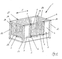
- FIGS. 1 to 3 recognizes bed 1 according to the invention - here designed as a cot - has a bed frame 2. End of the bed frame 2 is a head part 3 and the other end of the bed frame 2, a foot part 4 is provided. In the longitudinal direction 5 of the bed frame 2, two side parts are arranged between the head part 3 on the one hand and the foot part 4, wherein the one side part along the one longitudinal edge and the other side part along the other longitudinal edge of the bed frame 2 extends.
- the one side part is formed as a side rail 25, and the other side part has two side rails 6, wherein the one side rail 6 pivotally mounted on the head part 3 and the other side rail 6 are pivotally mounted on the foot part 4.
- the bed frame 2 takes in the final assembled state in the figures not shown in detail lying surface element, which in turn serves to support a mattress 26, a cushion element and / or the like.
- a lying surface element may, for example, be a slatted frame.
- the two side rails 6 of the reference to the drawing plane Fig. 1 The two side rail parts 7 and 8 are each arranged relatively pivotable to each other, with the interposition of a common hinge strut 9.
- the respective side rail part 7 of a side rail 6 is arranged pivotably on the respectively associated post 23 of the head part 3 or of the foot part 4.
- the respective post 23 provides an axis of rotation about which the respective side rail 6 is pivotable.
- Fig. 1 shows the two side rails 6 in the use position, that is in the closed position, in which a person lying in bed is protected from accidental falling out of the bed 1.
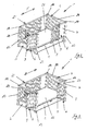
- Fig. 2 shows the one side rail 6 in the open position, that is in non-use position, whereas the other side rail 6 is still in use position.
- Fig. 3 finally shows the one side rail 6 in the position of use and the other side rail 6, namely that with respect to the plane of the drawing Fig. 3 right side rail 6 in the partially open position, in which position the side rail part 7 of the side rail 6 unverschwenkt, the side rail part 8, however, is pivoted relative to the side rail part 7.
- the head or the foot part 3, 4 each have an end piece 24 and two posts 23, wherein the end piece 24 is disposed between the two posts 23.
- the end piece 24 is formed of longitudinal struts and cross struts.
- other embodiments of a head or foot part 3, 4 may be provided.
- the side rails 6 are each pivotally mounted on the head or foot 3, 4, wherein the side rails 6 each have two relatively pivotally formed side rail parts 7 and 8, wherein the side rail parts 7 and 8 respectively not directly, but indirectly coupled with the interposition of a common hinge strut 9 to each other.
- the joint strut 9 two spaced apart pivot axes 10 and 11 ready, which in particular from a synopsis of FIGS. 7 and 8 shows that the distance A between the two pivot axes 10 and 11 corresponds to the geometric dimensions of the side rail 6 in the thickness direction.
- This embodiment has the advantage that the second side rail part 8 can be pivoted by 180 ° in relation to the first side rail part 7, namely counterclockwise by 180 ° and by 180 ° in the clockwise direction when the side rail part 7 is pivoted.
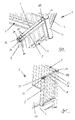
- a side rail 6 on the associated post 23 of the head or foot part 3, 4 serve according Fig. 6 Joint parts 14, wherein the one hinge part 14 at the upper end edge and the other hinge part 14 at the lower end edge of the respectively associated post 23 of the head or foot part 3, 4 are arranged.
- the two each post 23 provided hinge pin 12 are in alignment and so together form a pivot axis about which the respective side rail 6 is pivotable around.
- each hinge pin 12 With the interposition of a plastic bushing 16 formed a fitting 15.
- This connector 15 has a ring 17 and a sword 18, wherein the sword 18 engages in a correspondingly shaped receptacle 20 of the associated side rail 6.
- the sword 20 is screwed to the side rails 6, for which purpose the sword 20 has holes 19, as this particular from the Exploded view according to Fig. 6 results.
- the side rail 6 is pivotally arranged around the associated post 23, whereby a pivoting movement takes place through the pivot axis formed by the two hinge pins 12.
- the post 23 is equipped on the upper side with a post cover 27.
- This post cover 27 may be, for example, a disk formed of plastic, which covers the top of the profile element forming the post 23, for example of aluminum.
- the post 23 provides a channel 28 for receiving the hinge pin 12. In the final assembled state, the hinge pin 12 engages in this channel 28.
- the ring 17 carries a ring cover 21 which is followed by a cap 13 carried by the hinge pin 12. Together, the hinge pin 12 and the cover 13 form the hinge part 14.
- To cover also the sword 20 is a formed sword plastic cover 22nd
- the bearing bushing 16 is preferably arranged within the channel 28 provided by the post 23 and represents a guide contour for the hinge pin 12.
- the hinge pin 12 is preferably replaceably received by this guide contour. It is possible in this respect to replace the hinge pin 12 providing the hinge part, if necessary.
- FIGS. 4 and 5 let on the one hand the headboard side rail 6 in non-use position or recognize the predominantlyteil workede side rails 6 in the partially open position.
- the side rails 6 are arranged pivotably about the associated post 23 due to the articulated arrangement of the respective side rail part 7.
- a pivoting movement of the side rail 6 to the respectively associated post 23 by preferably 270 ° is possible.
- a pivoting movement of the side rail part 8 relative to the side rail part 7 is permitted, wherein due to the interposition of the hinge strut 9, a pivoting movement of the side rail part 8 relative to the side rail part 7 by up to 360 ° is possible.
- FIGS. 7 to 9 can be seen in detail the provided according to the invention Gefenkstrebe 9.
- the Articulated strut 9 provides the articulated strut 9 two pivot axes 10 and 11 spaced apart from each other, wherein in particular from FIG Fig. 7 shows that the distance A between the two pivot axes 10 and 11 corresponds to the geometric dimensions of the side rail 6 in the thickness direction.
- This embodiment has the advantage that the second side rail part 8 can be pivoted by 360 ° in relation to the first side rail part 7, wherein from a synopsis of the FIGS. 7 and 8 shows that the side rail part 8 after Fig. 8 towards the direction Fig. 7 is pivoted by 180 °.
- Fig. 9 lets the coupling of the two side rail parts 7 and 8 to the hinge strut 9 in detail in an exploded view recognize. It shows Fig. 9 the upper edge in the height direction. The lower end edge, not shown in the figures, is formed in an identical manner to the upper end edge.
- Fig. 9 results in the articulated strut 9 frontally two threaded sleeves 29 and 30 ready. These define in the final assembled state, the two later pivot axes 10 and 11. Of each sleeve 29 and 30 pivotally received a hinge flange 31 is provided. This has a ring 32 and a sword 33. In the final assembled state of the ring 32 surrounds the associated sleeve 29 and 30 and the sword 33 is inserted into a corresponding receptacle of the associated side rail part 7 and 8 respectively. For connection to the associated side rail part, the respective sword 33 has holes through which connection screws are guided in the final assembled state.
- the hinge flange 31 is covered on the upper side by means of an essay, not least for optical reasons.
- the article has a ring cover 34 and a sword cover 35.
- screws 36 are provided, which engage with the interposition of a washer 37 in the respectively associated threaded sleeve 29 and 30 respectively.
- FIGS. 10 and 11 let recognize another special feature.
- the side rail arrangement consisting of head part 3, foot part 4 and side rails 42 and 6 is spaced from mattress 26, forming a circumferential gap 38, which is received by a lying surface element not illustrated in the figures .
- This circumferential gap 38 is used in the intended use of receiving the lower edge of a non-illustrated in the figures upholstery, which is to install on the inside of the side rail assembly.
- a spacer is provided, which in the exemplary embodiment shown is a peripheral frame 39, for example made of wood, as this is in particular FIG. 10 lets recognize.
- the frame 39 is formed as a profile element and surrounds the mattress 26 like a frame.
- bed 1 according to the invention has two wing-like side rails 6, which can be transferred from a use position to a non-use position and vice versa.
- a locking device 40 To fix the side rails 6 in the position of use each side rail 6 is a locking device 40, as they are from a synopsis of FIGS. 12 to 14 results.
- the per side rails 6 provided latching device 40 has a bed-side locking receptacle 42 on the one hand and on a side grid side latching part 41 on the other.
- each side grid 6 two such locking devices 40 are provided, namely each side gate part 7 and 8, a locking device 40th
- locking parts 41 are each retracted into the associated locking receptacles 42 and fixed thanks to a provided by the respective locking receptacle 42 locking pin 45 in position.
- the latching receptacle 42 has a latching device 40, in particular Fig. 13 can be removed, via a base plate 43. This bears bedside two pins 44, which engage in the assembled state in corresponding bed-side holes.
- the locking receptacle 42 further has a movable in the height direction 56 and received by a housing 48 locking pin 45, which is designed to be spring-loaded and therefore has the aspiration, in the in FIGS. 13 and 14 To move shown locking position.
- this has a handle 47.
- the latching part 41 has a latching lever 50, which is mounted pivotably about a rotation axis 51.
- the latching lever 50 provides the catch side a bore 52 ready, with the locking pin 45 cooperates with its latching end portion 46, as the locked position in accordance with Fig. 14 shows.
- the latching lever 50 has the catch side on a casserole contour 53, which ends at a transfer of the side rail 6 from a non-use position in the use position end to the locking pin 45.
- the detent lever 50 pivots about the axis of rotation 51, with respect to the plane of the drawing Fig. 14 counterclockwise. This pivoting movement of the locking lever 50 allows retraction of the locking pin 45 in the locking lever 50 rastpin varnish provided bore 52.
- the twisting movement of the locking lever 50 about the axis of rotation 51 is against the spring force of a spring tongue 54 which is supported with its end portion 55 relative to the locking lever 50.
- the latching lever 50 is due to this spring force acting on it endeavors, in the latched position according to Fig. 14 to remain.
- the locking pin 45 In order to transfer a side rail 6 from the position of use to an open non-use position, the locking pin 45 is to be moved in the height direction 56 downward. As a result, the locking lever 50 is released and an extension of the locking part 41 from the locking receptacle 42, thus pivoting the side rail 6 is possible.
- the blocking tab 49 In order to be able to move the latching pin 45 downwards with respect to the height direction 56, the blocking tab 49 is first to be pivoted on the user side in the direction of the base plate 43 of the latching receptacle 42. Only when the blocking lug 49 is in the pivoted position, the latching pin 45 is released, thus a method of the same is permitted by the user.
Landscapes
- Health & Medical Sciences (AREA)
- Nursing (AREA)
- Life Sciences & Earth Sciences (AREA)
- Animal Behavior & Ethology (AREA)
- General Health & Medical Sciences (AREA)
- Public Health (AREA)
- Veterinary Medicine (AREA)
- Invalid Beds And Related Equipment (AREA)
Priority Applications (1)
| Application Number | Priority Date | Filing Date | Title |
|---|---|---|---|
| EP14187363.8A EP3002000B1 (fr) | 2014-10-01 | 2014-10-01 | Lit, en particulier lit de malade et/ou de soin |
Applications Claiming Priority (1)
| Application Number | Priority Date | Filing Date | Title |
|---|---|---|---|
| EP14187363.8A EP3002000B1 (fr) | 2014-10-01 | 2014-10-01 | Lit, en particulier lit de malade et/ou de soin |
Publications (2)
| Publication Number | Publication Date |
|---|---|
| EP3002000A1 true EP3002000A1 (fr) | 2016-04-06 |
| EP3002000B1 EP3002000B1 (fr) | 2016-09-21 |
Family
ID=51626482
Family Applications (1)
| Application Number | Title | Priority Date | Filing Date |
|---|---|---|---|
| EP14187363.8A Not-in-force EP3002000B1 (fr) | 2014-10-01 | 2014-10-01 | Lit, en particulier lit de malade et/ou de soin |
Country Status (1)
| Country | Link |
|---|---|
| EP (1) | EP3002000B1 (fr) |
Cited By (1)
| Publication number | Priority date | Publication date | Assignee | Title |
|---|---|---|---|---|
| US20240133222A1 (en) * | 2019-04-05 | 2024-04-25 | Lifetime Products, Inc. | Double jointed door hinge |
Citations (4)
| Publication number | Priority date | Publication date | Assignee | Title |
|---|---|---|---|---|
| DE29612398U1 (de) * | 1996-07-17 | 1996-10-24 | SAVI Möbel GmbH, 48691 Vreden | Behindertengerechtes Kranken-/Kinderbett |
| US20120223283A1 (en) * | 2011-03-04 | 2012-09-06 | Richell Corporation | Convertible Pet Barrier With a Connection Member |
| US8397321B1 (en) * | 2012-03-12 | 2013-03-19 | Brack Smith | Wheel chair accessible crib |
| US8566979B1 (en) * | 2012-05-30 | 2013-10-29 | Peter Kayser | Infant crib having paired sets of vertically hinged doors for creating opening along entire sidewall |
-
2014
- 2014-10-01 EP EP14187363.8A patent/EP3002000B1/fr not_active Not-in-force
Patent Citations (4)
| Publication number | Priority date | Publication date | Assignee | Title |
|---|---|---|---|---|
| DE29612398U1 (de) * | 1996-07-17 | 1996-10-24 | SAVI Möbel GmbH, 48691 Vreden | Behindertengerechtes Kranken-/Kinderbett |
| US20120223283A1 (en) * | 2011-03-04 | 2012-09-06 | Richell Corporation | Convertible Pet Barrier With a Connection Member |
| US8397321B1 (en) * | 2012-03-12 | 2013-03-19 | Brack Smith | Wheel chair accessible crib |
| US8566979B1 (en) * | 2012-05-30 | 2013-10-29 | Peter Kayser | Infant crib having paired sets of vertically hinged doors for creating opening along entire sidewall |
Cited By (2)
| Publication number | Priority date | Publication date | Assignee | Title |
|---|---|---|---|---|
| US20240133222A1 (en) * | 2019-04-05 | 2024-04-25 | Lifetime Products, Inc. | Double jointed door hinge |
| US12460459B2 (en) * | 2019-04-05 | 2025-11-04 | Lifetime Products, Inc. | Double jointed door hinge |
Also Published As
| Publication number | Publication date |
|---|---|
| EP3002000B1 (fr) | 2016-09-21 |
Similar Documents
| Publication | Publication Date | Title |
|---|---|---|
| AT515135B1 (de) | Scharnier, insbesondere für ein Möbelstück | |
| EP2364685B1 (fr) | Lit, en particulier lit de malade et/ou de soin | |
| DE60310000T2 (de) | Schlossanordnung für Sektionaltore | |
| DE102008062774A1 (de) | Türschutzgitter | |
| DE69901167T2 (de) | Klapptisch | |
| DE102011050395A1 (de) | Beschlag für eine Schiebetür | |
| DE202020105174U1 (de) | Sicherheitstor | |
| EP3002000B1 (fr) | Lit, en particulier lit de malade et/ou de soin | |
| EP2078812A2 (fr) | Elément de recouvrement pour un rail de guidage | |
| EP2649907B1 (fr) | Barreau latéral pour lit | |
| EP3001999B1 (fr) | Lit, en particulier lit de malade et/ou de soin | |
| EP3158907A1 (fr) | Barre d'appui pivotable et pliable, en particulier pour le domaine sanitaire | |
| EP3851004A1 (fr) | Dispositif de montage destiné au montage amovible d'une pièce de garniture sur un corps de wc | |
| EP3270859A1 (fr) | Lit réglable en hauteur | |
| EP2134306B1 (fr) | Grille latérale | |
| DE202007004269U1 (de) | Bett | |
| DE102013101362B4 (de) | Seitengitter für ein Bett | |
| EP2908700B1 (fr) | Barreau latéral pour lit | |
| EP1358824A1 (fr) | Dispositif de verrouillage | |
| DE102004052309B4 (de) | Möbel | |
| DE102023125789A1 (de) | Seitengitter für ein Bett | |
| DE8201832U1 (de) | Falzschere für um eine waagerechte Achse schwenkbare Flügel von Fenstern, Türen und dergleichen | |
| DE4412607C2 (de) | Gelenk | |
| DE102016201315A1 (de) | Pflegebett | |
| DE102021125772A1 (de) | Abstandhalter, Führungsschiene für einen Raffstore oder eine Jalousie sowie Raffstore und Jalousie und Verfahren hierfür |
Legal Events
| Date | Code | Title | Description |
|---|---|---|---|
| PUAI | Public reference made under article 153(3) epc to a published international application that has entered the european phase |
Free format text: ORIGINAL CODE: 0009012 |
|
| 17P | Request for examination filed |
Effective date: 20150911 |
|
| AK | Designated contracting states |
Kind code of ref document: A1 Designated state(s): AL AT BE BG CH CY CZ DE DK EE ES FI FR GB GR HR HU IE IS IT LI LT LU LV MC MK MT NL NO PL PT RO RS SE SI SK SM TR |
|
| AX | Request for extension of the european patent |
Extension state: BA ME |
|
| GRAP | Despatch of communication of intention to grant a patent |
Free format text: ORIGINAL CODE: EPIDOSNIGR1 |
|
| INTG | Intention to grant announced |
Effective date: 20160428 |
|
| GRAS | Grant fee paid |
Free format text: ORIGINAL CODE: EPIDOSNIGR3 |
|
| GRAA | (expected) grant |
Free format text: ORIGINAL CODE: 0009210 |
|
| AK | Designated contracting states |
Kind code of ref document: B1 Designated state(s): AL AT BE BG CH CY CZ DE DK EE ES FI FR GB GR HR HU IE IS IT LI LT LU LV MC MK MT NL NO PL PT RO RS SE SI SK SM TR |
|
| REG | Reference to a national code |
Ref country code: GB Ref legal event code: FG4D Free format text: NOT ENGLISH |
|
| REG | Reference to a national code |
Ref country code: CH Ref legal event code: EP |
|
| REG | Reference to a national code |
Ref country code: AT Ref legal event code: REF Ref document number: 830449 Country of ref document: AT Kind code of ref document: T Effective date: 20161015 |
|
| REG | Reference to a national code |
Ref country code: IE Ref legal event code: FG4D Free format text: LANGUAGE OF EP DOCUMENT: GERMAN |
|
| REG | Reference to a national code |
Ref country code: DE Ref legal event code: R096 Ref document number: 502014001513 Country of ref document: DE |
|
| REG | Reference to a national code |
Ref country code: CH Ref legal event code: NV Representative=s name: E. BLUM AND CO. AG PATENT- UND MARKENANWAELTE , CH |
|
| REG | Reference to a national code |
Ref country code: FR Ref legal event code: PLFP Year of fee payment: 3 |
|
| REG | Reference to a national code |
Ref country code: NL Ref legal event code: FP |
|
| REG | Reference to a national code |
Ref country code: LT Ref legal event code: MG4D |
|
| PG25 | Lapsed in a contracting state [announced via postgrant information from national office to epo] |
Ref country code: NO Free format text: LAPSE BECAUSE OF FAILURE TO SUBMIT A TRANSLATION OF THE DESCRIPTION OR TO PAY THE FEE WITHIN THE PRESCRIBED TIME-LIMIT Effective date: 20161221 Ref country code: FI Free format text: LAPSE BECAUSE OF FAILURE TO SUBMIT A TRANSLATION OF THE DESCRIPTION OR TO PAY THE FEE WITHIN THE PRESCRIBED TIME-LIMIT Effective date: 20160921 Ref country code: LT Free format text: LAPSE BECAUSE OF FAILURE TO SUBMIT A TRANSLATION OF THE DESCRIPTION OR TO PAY THE FEE WITHIN THE PRESCRIBED TIME-LIMIT Effective date: 20160921 Ref country code: RS Free format text: LAPSE BECAUSE OF FAILURE TO SUBMIT A TRANSLATION OF THE DESCRIPTION OR TO PAY THE FEE WITHIN THE PRESCRIBED TIME-LIMIT Effective date: 20160921 |
|
| PG25 | Lapsed in a contracting state [announced via postgrant information from national office to epo] |
Ref country code: LV Free format text: LAPSE BECAUSE OF FAILURE TO SUBMIT A TRANSLATION OF THE DESCRIPTION OR TO PAY THE FEE WITHIN THE PRESCRIBED TIME-LIMIT Effective date: 20160921 Ref country code: SE Free format text: LAPSE BECAUSE OF FAILURE TO SUBMIT A TRANSLATION OF THE DESCRIPTION OR TO PAY THE FEE WITHIN THE PRESCRIBED TIME-LIMIT Effective date: 20160921 Ref country code: BE Free format text: LAPSE BECAUSE OF NON-PAYMENT OF DUE FEES Effective date: 20161031 Ref country code: GR Free format text: LAPSE BECAUSE OF FAILURE TO SUBMIT A TRANSLATION OF THE DESCRIPTION OR TO PAY THE FEE WITHIN THE PRESCRIBED TIME-LIMIT Effective date: 20161222 |
|
| PG25 | Lapsed in a contracting state [announced via postgrant information from national office to epo] |
Ref country code: RO Free format text: LAPSE BECAUSE OF FAILURE TO SUBMIT A TRANSLATION OF THE DESCRIPTION OR TO PAY THE FEE WITHIN THE PRESCRIBED TIME-LIMIT Effective date: 20160921 Ref country code: EE Free format text: LAPSE BECAUSE OF FAILURE TO SUBMIT A TRANSLATION OF THE DESCRIPTION OR TO PAY THE FEE WITHIN THE PRESCRIBED TIME-LIMIT Effective date: 20160921 |
|
| PG25 | Lapsed in a contracting state [announced via postgrant information from national office to epo] |
Ref country code: PL Free format text: LAPSE BECAUSE OF FAILURE TO SUBMIT A TRANSLATION OF THE DESCRIPTION OR TO PAY THE FEE WITHIN THE PRESCRIBED TIME-LIMIT Effective date: 20160921 Ref country code: PT Free format text: LAPSE BECAUSE OF FAILURE TO SUBMIT A TRANSLATION OF THE DESCRIPTION OR TO PAY THE FEE WITHIN THE PRESCRIBED TIME-LIMIT Effective date: 20170123 Ref country code: SK Free format text: LAPSE BECAUSE OF FAILURE TO SUBMIT A TRANSLATION OF THE DESCRIPTION OR TO PAY THE FEE WITHIN THE PRESCRIBED TIME-LIMIT Effective date: 20160921 Ref country code: CZ Free format text: LAPSE BECAUSE OF FAILURE TO SUBMIT A TRANSLATION OF THE DESCRIPTION OR TO PAY THE FEE WITHIN THE PRESCRIBED TIME-LIMIT Effective date: 20160921 Ref country code: BG Free format text: LAPSE BECAUSE OF FAILURE TO SUBMIT A TRANSLATION OF THE DESCRIPTION OR TO PAY THE FEE WITHIN THE PRESCRIBED TIME-LIMIT Effective date: 20161221 Ref country code: IS Free format text: LAPSE BECAUSE OF FAILURE TO SUBMIT A TRANSLATION OF THE DESCRIPTION OR TO PAY THE FEE WITHIN THE PRESCRIBED TIME-LIMIT Effective date: 20170121 Ref country code: SM Free format text: LAPSE BECAUSE OF FAILURE TO SUBMIT A TRANSLATION OF THE DESCRIPTION OR TO PAY THE FEE WITHIN THE PRESCRIBED TIME-LIMIT Effective date: 20160921 Ref country code: ES Free format text: LAPSE BECAUSE OF FAILURE TO SUBMIT A TRANSLATION OF THE DESCRIPTION OR TO PAY THE FEE WITHIN THE PRESCRIBED TIME-LIMIT Effective date: 20160921 |
|
| REG | Reference to a national code |
Ref country code: DE Ref legal event code: R097 Ref document number: 502014001513 Country of ref document: DE |
|
| PG25 | Lapsed in a contracting state [announced via postgrant information from national office to epo] |
Ref country code: IT Free format text: LAPSE BECAUSE OF FAILURE TO SUBMIT A TRANSLATION OF THE DESCRIPTION OR TO PAY THE FEE WITHIN THE PRESCRIBED TIME-LIMIT Effective date: 20160921 |
|
| REG | Reference to a national code |
Ref country code: IE Ref legal event code: MM4A |
|
| PLBE | No opposition filed within time limit |
Free format text: ORIGINAL CODE: 0009261 |
|
| STAA | Information on the status of an ep patent application or granted ep patent |
Free format text: STATUS: NO OPPOSITION FILED WITHIN TIME LIMIT |
|
| PG25 | Lapsed in a contracting state [announced via postgrant information from national office to epo] |
Ref country code: DK Free format text: LAPSE BECAUSE OF FAILURE TO SUBMIT A TRANSLATION OF THE DESCRIPTION OR TO PAY THE FEE WITHIN THE PRESCRIBED TIME-LIMIT Effective date: 20160921 |
|
| 26N | No opposition filed |
Effective date: 20170622 |
|
| PG25 | Lapsed in a contracting state [announced via postgrant information from national office to epo] |
Ref country code: LU Free format text: LAPSE BECAUSE OF NON-PAYMENT OF DUE FEES Effective date: 20161001 |
|
| REG | Reference to a national code |
Ref country code: FR Ref legal event code: PLFP Year of fee payment: 4 |
|
| PG25 | Lapsed in a contracting state [announced via postgrant information from national office to epo] |
Ref country code: IE Free format text: LAPSE BECAUSE OF NON-PAYMENT OF DUE FEES Effective date: 20161001 Ref country code: SI Free format text: LAPSE BECAUSE OF FAILURE TO SUBMIT A TRANSLATION OF THE DESCRIPTION OR TO PAY THE FEE WITHIN THE PRESCRIBED TIME-LIMIT Effective date: 20160921 |
|
| REG | Reference to a national code |
Ref country code: BE Ref legal event code: MM Effective date: 20161031 |
|
| PGFP | Annual fee paid to national office [announced via postgrant information from national office to epo] |
Ref country code: FR Payment date: 20171024 Year of fee payment: 4 |
|
| REG | Reference to a national code |
Ref country code: DE Ref legal event code: R082 Ref document number: 502014001513 Country of ref document: DE Representative=s name: BRINKMANN & PARTNER PATENTANWAELTE PARTNERSCHA, DE Ref country code: DE Ref legal event code: R082 Ref document number: 502014001513 Country of ref document: DE Representative=s name: RAUSCH WANISCHECK-BERGMANN BRINKMANN PARTNERSC, DE |
|
| PGFP | Annual fee paid to national office [announced via postgrant information from national office to epo] |
Ref country code: NL Payment date: 20171019 Year of fee payment: 4 Ref country code: CH Payment date: 20171019 Year of fee payment: 4 |
|
| PG25 | Lapsed in a contracting state [announced via postgrant information from national office to epo] |
Ref country code: HU Free format text: LAPSE BECAUSE OF FAILURE TO SUBMIT A TRANSLATION OF THE DESCRIPTION OR TO PAY THE FEE WITHIN THE PRESCRIBED TIME-LIMIT; INVALID AB INITIO Effective date: 20141001 |
|
| PG25 | Lapsed in a contracting state [announced via postgrant information from national office to epo] |
Ref country code: MK Free format text: LAPSE BECAUSE OF FAILURE TO SUBMIT A TRANSLATION OF THE DESCRIPTION OR TO PAY THE FEE WITHIN THE PRESCRIBED TIME-LIMIT Effective date: 20160921 Ref country code: MC Free format text: LAPSE BECAUSE OF FAILURE TO SUBMIT A TRANSLATION OF THE DESCRIPTION OR TO PAY THE FEE WITHIN THE PRESCRIBED TIME-LIMIT Effective date: 20160921 Ref country code: MT Free format text: LAPSE BECAUSE OF FAILURE TO SUBMIT A TRANSLATION OF THE DESCRIPTION OR TO PAY THE FEE WITHIN THE PRESCRIBED TIME-LIMIT Effective date: 20160921 Ref country code: HR Free format text: LAPSE BECAUSE OF FAILURE TO SUBMIT A TRANSLATION OF THE DESCRIPTION OR TO PAY THE FEE WITHIN THE PRESCRIBED TIME-LIMIT Effective date: 20160921 Ref country code: CY Free format text: LAPSE BECAUSE OF FAILURE TO SUBMIT A TRANSLATION OF THE DESCRIPTION OR TO PAY THE FEE WITHIN THE PRESCRIBED TIME-LIMIT Effective date: 20160921 |
|
| PG25 | Lapsed in a contracting state [announced via postgrant information from national office to epo] |
Ref country code: AL Free format text: LAPSE BECAUSE OF FAILURE TO SUBMIT A TRANSLATION OF THE DESCRIPTION OR TO PAY THE FEE WITHIN THE PRESCRIBED TIME-LIMIT Effective date: 20160921 Ref country code: TR Free format text: LAPSE BECAUSE OF FAILURE TO SUBMIT A TRANSLATION OF THE DESCRIPTION OR TO PAY THE FEE WITHIN THE PRESCRIBED TIME-LIMIT Effective date: 20160921 |
|
| REG | Reference to a national code |
Ref country code: CH Ref legal event code: PL |
|
| REG | Reference to a national code |
Ref country code: NL Ref legal event code: MM Effective date: 20181101 |
|
| GBPC | Gb: european patent ceased through non-payment of renewal fee |
Effective date: 20181001 |
|
| PG25 | Lapsed in a contracting state [announced via postgrant information from national office to epo] |
Ref country code: NL Free format text: LAPSE BECAUSE OF NON-PAYMENT OF DUE FEES Effective date: 20181101 |
|
| PG25 | Lapsed in a contracting state [announced via postgrant information from national office to epo] |
Ref country code: CH Free format text: LAPSE BECAUSE OF NON-PAYMENT OF DUE FEES Effective date: 20181031 Ref country code: FR Free format text: LAPSE BECAUSE OF NON-PAYMENT OF DUE FEES Effective date: 20181031 Ref country code: LI Free format text: LAPSE BECAUSE OF NON-PAYMENT OF DUE FEES Effective date: 20181031 |
|
| PG25 | Lapsed in a contracting state [announced via postgrant information from national office to epo] |
Ref country code: GB Free format text: LAPSE BECAUSE OF NON-PAYMENT OF DUE FEES Effective date: 20181001 |
|
| REG | Reference to a national code |
Ref country code: AT Ref legal event code: MM01 Ref document number: 830449 Country of ref document: AT Kind code of ref document: T Effective date: 20191001 |
|
| PG25 | Lapsed in a contracting state [announced via postgrant information from national office to epo] |
Ref country code: AT Free format text: LAPSE BECAUSE OF NON-PAYMENT OF DUE FEES Effective date: 20191001 |
|
| PGFP | Annual fee paid to national office [announced via postgrant information from national office to epo] |
Ref country code: DE Payment date: 20211221 Year of fee payment: 8 |
|
| REG | Reference to a national code |
Ref country code: DE Ref legal event code: R119 Ref document number: 502014001513 Country of ref document: DE |
|
| PG25 | Lapsed in a contracting state [announced via postgrant information from national office to epo] |
Ref country code: DE Free format text: LAPSE BECAUSE OF NON-PAYMENT OF DUE FEES Effective date: 20230503 |