EP3000539B1 - VERFAHREN ZUM GIEßEN UND WALZEN EINES ENDLOSEN STRANGGUTES - Google Patents
VERFAHREN ZUM GIEßEN UND WALZEN EINES ENDLOSEN STRANGGUTES Download PDFInfo
- Publication number
- EP3000539B1 EP3000539B1 EP14186114.6A EP14186114A EP3000539B1 EP 3000539 B1 EP3000539 B1 EP 3000539B1 EP 14186114 A EP14186114 A EP 14186114A EP 3000539 B1 EP3000539 B1 EP 3000539B1
- Authority
- EP
- European Patent Office
- Prior art keywords
- strip
- rolling
- casting machine
- drive
- soll
- Prior art date
- Legal status (The legal status is an assumption and is not a legal conclusion. Google has not performed a legal analysis and makes no representation as to the accuracy of the status listed.)
- Active
Links
Images


Classifications
-
- B—PERFORMING OPERATIONS; TRANSPORTING
- B21—MECHANICAL METAL-WORKING WITHOUT ESSENTIALLY REMOVING MATERIAL; PUNCHING METAL
- B21B—ROLLING OF METAL
- B21B37/00—Control devices or methods specially adapted for metal-rolling mills or the work produced thereby
- B21B37/46—Roll speed or drive motor control
-
- B—PERFORMING OPERATIONS; TRANSPORTING
- B22—CASTING; POWDER METALLURGY
- B22D—CASTING OF METALS; CASTING OF OTHER SUBSTANCES BY THE SAME PROCESSES OR DEVICES
- B22D11/00—Continuous casting of metals, i.e. casting in indefinite lengths
- B22D11/16—Controlling or regulating processes or operations
- B22D11/20—Controlling or regulating processes or operations for removing cast stock
-
- B—PERFORMING OPERATIONS; TRANSPORTING
- B21—MECHANICAL METAL-WORKING WITHOUT ESSENTIALLY REMOVING MATERIAL; PUNCHING METAL
- B21B—ROLLING OF METAL
- B21B1/00—Metal-rolling methods or mills for making semi-finished products of solid or profiled cross-section; Sequence of operations in milling trains; Layout of rolling-mill plant, e.g. grouping of stands; Succession of passes or of sectional pass alternations
- B21B1/46—Metal-rolling methods or mills for making semi-finished products of solid or profiled cross-section; Sequence of operations in milling trains; Layout of rolling-mill plant, e.g. grouping of stands; Succession of passes or of sectional pass alternations for rolling metal immediately subsequent to continuous casting
- B21B1/463—Metal-rolling methods or mills for making semi-finished products of solid or profiled cross-section; Sequence of operations in milling trains; Layout of rolling-mill plant, e.g. grouping of stands; Succession of passes or of sectional pass alternations for rolling metal immediately subsequent to continuous casting in a continuous process, i.e. the cast not being cut before rolling
-
- B—PERFORMING OPERATIONS; TRANSPORTING
- B21—MECHANICAL METAL-WORKING WITHOUT ESSENTIALLY REMOVING MATERIAL; PUNCHING METAL
- B21B—ROLLING OF METAL
- B21B11/00—Subsidising the rolling process by subjecting rollers or work to vibrations, e.g. ultrasonic vibrations
-
- B—PERFORMING OPERATIONS; TRANSPORTING
- B21—MECHANICAL METAL-WORKING WITHOUT ESSENTIALLY REMOVING MATERIAL; PUNCHING METAL
- B21B—ROLLING OF METAL
- B21B37/00—Control devices or methods specially adapted for metal-rolling mills or the work produced thereby
-
- B—PERFORMING OPERATIONS; TRANSPORTING
- B21—MECHANICAL METAL-WORKING WITHOUT ESSENTIALLY REMOVING MATERIAL; PUNCHING METAL
- B21B—ROLLING OF METAL
- B21B37/00—Control devices or methods specially adapted for metal-rolling mills or the work produced thereby
- B21B37/16—Control of thickness, width, diameter or other transverse dimensions
- B21B37/24—Automatic variation of thickness according to a predetermined program
- B21B37/26—Automatic variation of thickness according to a predetermined program for obtaining one strip having successive lengths of different constant thickness
-
- B—PERFORMING OPERATIONS; TRANSPORTING
- B21—MECHANICAL METAL-WORKING WITHOUT ESSENTIALLY REMOVING MATERIAL; PUNCHING METAL
- B21B—ROLLING OF METAL
- B21B38/00—Methods or devices for measuring, detecting or monitoring specially adapted for metal-rolling mills, e.g. position detection, inspection of the product
-
- B—PERFORMING OPERATIONS; TRANSPORTING
- B22—CASTING; POWDER METALLURGY
- B22D—CASTING OF METALS; CASTING OF OTHER SUBSTANCES BY THE SAME PROCESSES OR DEVICES
- B22D11/00—Continuous casting of metals, i.e. casting in indefinite lengths
- B22D11/06—Continuous casting of metals, i.e. casting in indefinite lengths into moulds with travelling walls, e.g. with rolls, plates, belts, caterpillars
- B22D11/0622—Continuous casting of metals, i.e. casting in indefinite lengths into moulds with travelling walls, e.g. with rolls, plates, belts, caterpillars formed by two casting wheels
-
- B—PERFORMING OPERATIONS; TRANSPORTING
- B22—CASTING; POWDER METALLURGY
- B22D—CASTING OF METALS; CASTING OF OTHER SUBSTANCES BY THE SAME PROCESSES OR DEVICES
- B22D11/00—Continuous casting of metals, i.e. casting in indefinite lengths
- B22D11/12—Accessories for subsequent treating or working cast stock in situ
- B22D11/1226—Accessories for subsequent treating or working cast stock in situ for straightening strands
-
- B—PERFORMING OPERATIONS; TRANSPORTING
- B22—CASTING; POWDER METALLURGY
- B22D—CASTING OF METALS; CASTING OF OTHER SUBSTANCES BY THE SAME PROCESSES OR DEVICES
- B22D11/00—Continuous casting of metals, i.e. casting in indefinite lengths
- B22D11/12—Accessories for subsequent treating or working cast stock in situ
- B22D11/124—Accessories for subsequent treating or working cast stock in situ for cooling
-
- B—PERFORMING OPERATIONS; TRANSPORTING
- B22—CASTING; POWDER METALLURGY
- B22D—CASTING OF METALS; CASTING OF OTHER SUBSTANCES BY THE SAME PROCESSES OR DEVICES
- B22D11/00—Continuous casting of metals, i.e. casting in indefinite lengths
- B22D11/14—Plants for continuous casting
- B22D11/142—Plants for continuous casting for curved casting
-
- B—PERFORMING OPERATIONS; TRANSPORTING
- B22—CASTING; POWDER METALLURGY
- B22D—CASTING OF METALS; CASTING OF OTHER SUBSTANCES BY THE SAME PROCESSES OR DEVICES
- B22D11/00—Continuous casting of metals, i.e. casting in indefinite lengths
- B22D11/14—Plants for continuous casting
- B22D11/143—Plants for continuous casting for horizontal casting
-
- B—PERFORMING OPERATIONS; TRANSPORTING
- B22—CASTING; POWDER METALLURGY
- B22D—CASTING OF METALS; CASTING OF OTHER SUBSTANCES BY THE SAME PROCESSES OR DEVICES
- B22D11/00—Continuous casting of metals, i.e. casting in indefinite lengths
- B22D11/16—Controlling or regulating processes or operations
-
- B—PERFORMING OPERATIONS; TRANSPORTING
- B21—MECHANICAL METAL-WORKING WITHOUT ESSENTIALLY REMOVING MATERIAL; PUNCHING METAL
- B21B—ROLLING OF METAL
- B21B37/00—Control devices or methods specially adapted for metal-rolling mills or the work produced thereby
- B21B2037/002—Mass flow control
-
- B—PERFORMING OPERATIONS; TRANSPORTING
- B21—MECHANICAL METAL-WORKING WITHOUT ESSENTIALLY REMOVING MATERIAL; PUNCHING METAL
- B21B—ROLLING OF METAL
- B21B2275/00—Mill drive parameters
- B21B2275/10—Motor power; motor current
- B21B2275/12—Roll torque
-
- B—PERFORMING OPERATIONS; TRANSPORTING
- B22—CASTING; POWDER METALLURGY
- B22D—CASTING OF METALS; CASTING OF OTHER SUBSTANCES BY THE SAME PROCESSES OR DEVICES
- B22D11/00—Continuous casting of metals, i.e. casting in indefinite lengths
- B22D11/12—Accessories for subsequent treating or working cast stock in situ
- B22D11/1206—Accessories for subsequent treating or working cast stock in situ for plastic shaping of strands
-
- B—PERFORMING OPERATIONS; TRANSPORTING
- B22—CASTING; POWDER METALLURGY
- B22D—CASTING OF METALS; CASTING OF OTHER SUBSTANCES BY THE SAME PROCESSES OR DEVICES
- B22D11/00—Continuous casting of metals, i.e. casting in indefinite lengths
- B22D11/12—Accessories for subsequent treating or working cast stock in situ
- B22D11/128—Accessories for subsequent treating or working cast stock in situ for removing
- B22D11/1282—Vertical casting and curving the cast stock to the horizontal
Definitions
- the invention relates to a method and a casting-rolling plant for casting and rolling an endless strand of metal, in particular steel.
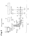
- FIG. 1 A known casting-rolling plant for casting and rolling an endless continuous material is exemplary in FIG. 1 shown.
- the casting / rolling plant 100 shown there comprises a continuous casting machine 110, a rolling mill 120 downstream of the continuous casting machine, a cooling section 170 downstream of the rolling line, a separating device 180 connected downstream of the cooling section, and a reeling device 190 for coiling the strand material 200
- Continuous casting machine 110 a mold 111, one of the mold downstream strand guide 112 and typically a separator 180.
- the separator 180 is used to separate a so-called cold strand.
- the melt solidifies in the mold and in this way, the strand shell of a strand material is formed.
- the thus formed, internally still liquid, extruded material is after leaving the mold 111 supported in the strand guide 112 by means of strand guide rollers 113 and deflected from the vertical to the horizontal.
- the strand guide rollers 113_i are actively driven at least partially by means of drives 114_i.
- the drives 114_i are driven by a strand guide roller drive controller 117.
- the roughing stands is followed by a heater, preferably an inductive heater 129, around the pre-rolled stock 200 to a desired finish rolling temperature to heat up before it subsequently enters a group of (finish) rolling stands 122_4 to N and is finish-rolled there to a desired final rolling thickness.
- the individual rolling stands 122_n are typically associated with individual drives 124_n, which are individually controlled by a higher-level drive control 128.
- the path coordinate which is equivalent to the casting direction or the material flow direction, is in FIG. 1 denoted by the reference numeral x.
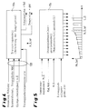
- FIG. 2 shows a detail of the just with reference to FIG. 1 described and known in the prior art casting-rolling plant 100.
- the same technical elements are shown, these are denoted by the same reference numerals as in FIG. 1 designated.
- the strand guide roller designated by the reference symbol 113a is not driven in contrast to the strand guide rollers 113_i.
- the sump tip 160 and its actual position along the path coordinate x are designated by the reference symbol X_S_Ist.
- the thicknesses of the product strand 200 at the exit of the continuous casting machine 110 are denoted by the reference H0, at the exit of the first rolling stand by the reference H1 and at the outlet of the second rolling stand by the reference H2.
- the essential characteristic in the production of endless extrudate 200 or in continuous rolling is that the extruded product 200 is not severed from its production in the mold 111 through its solidification in strand guide 112 until rolling or thickness reduction in the rolling mill 120.
- the above-mentioned separation of the dummy bar at the outlet of the strand guide 112 is not contradictory, because the cold strand is not yet the actual continuous strand material.
- a separation of the endless strand material takes place only with the help of the separator 180 in FIG. 1 immediate in front of the reeling device 190, in order then to cut the previously endlessly rolled stock 200 to desired coil lengths.
- the mass flow in a coupled casting-rolling process is basically constant at each point of the casting-rolling plant 100. Disturbances of this constancy, however, can occur, for example, when the strand 200 accumulates (loops then form) or when it is stretched (the strand can also tear in the limit). Causes of such discontinuities in the mass flow are z. For example, if the casting machine does not continuously nach culinaryt material or the mass flow or the reels do not provide adequate drainage of the mass flow or the strand material.
- Another possibility for controlling the mass flow, in particular within a (finished) rolling train is to incorporate a storage unit for the rolling stock in the mass flow and to control the mass flow by suitable variations of the stored volume of the material to be controlled.
- Such memory can z. B. be realized in the form of loop memories. With material thicknesses of the material to be extruded greater than 20 mm, depending on the material, however, form no loops due to high rigidity. Especially in the area behind the casting machine, this possibility can therefore not be used with the said large material thicknesses.
- a loop control is known, for example, from the Japanese patent application JP 2007185703 A ,
- the preamble of claim 1 is based on EP 2 346 625 B1 ,
- JP 55014133 A JP 55014134 A .
- JP S60 227958 A and JP 60221103 A as well as the German patent application DE 20 2004 010038 A1 directed.
- the invention has the object of developing a known method and a known casting-rolling plant for casting and rolling of extruded material to the effect that the drives of both the continuous casting machine as well as of the rolling mill with respect to one of the two plant parts the same and constant mass flow are synchronized in a higher order.
- the first rolling stand acts as a "speed master” or as a "mass flow master”.
- the mass flow results from the thickness of the material to be stranded at the inlet and at the outlet of the first stand and the speed of the work rolls of the first stand. The speed will, as will be described later, determined and specified by means of a pass schedule model.
- Another advantage of the claimed solution is that a speed detection can be saved both in the strand guide rollers as well as the rollers of the rolling stands.
- the claimed speed specification only in the first roll stand with simultaneous torque input for the strand guide rollers advantageously allows automatically the desired constancy of the mass flow in both parts of the plant, ie both in the continuous casting machine as well as in the rolling mill.
- Due to the claimed specification of the target speed with only a single drive within the continuous casting and the rolling mill ensures that it is not to disturbances in the constancy of mass flow, z. B. comes due to not exactly synchronized drives with speed specification.
- the thickness threshold is, for example, 40 - 20 mm. It depends on the material properties of the material to be extruded, for example on the modulus of elasticity of the material to be stranded.
- the slip is monitored by at least one of the strand guide rollers and, if necessary, counteracted when the risk of slippage of the slip-monitored strand guide roller is detected.
- the position of the sump tip of the strand material within the strand guide is controlled by suitable variations of manipulated variables to a predetermined desired position.
- the controlled system d. H. the solidification process in the continuous casting machine, simulated by means of a solidification model.
- the manipulated variables are calculated in absolute terms by a controller and output to the solidification model.
- the manipulated variables which may affect the position of the sump tip, it is in particular the strength of the cooling of the strand material in the casting machine, the cross-sectional format, in particular the thickness of the material at certain points within and at the output of the strand guide, the casting speed and the geometry the casting machine.
- the geometry of the casting machine reflects its mechanical structure, such as the length, the position of the roll, the shape of the mold, the arrangement of the cooling, etc.
- the invention provides that the desired torque for driving the at least one driven strand guide roller in accordance with the value for the thickness of the strand material at the output of the strand guide and the value for the casting speed, each in the steady state of the casting-rolling plant, as well calculated and specified in accordance with the value for the strand extraction sum moment and (the courses) of the strand shell thickness and the temperature of the strand material within and at the exit of the strand guide from the continuous casting machine drive model.
- the desired torques for the drives of the strand guide rollers over the length of the strand guide are given suitably distributed by the Strangg automatmaschinenAntriebsmodell, taking into account the continuous casting, the Strangauszugs cumulative moment and taking into account (the distribution) of the thickness of the strand shell and the temperature of the material over the length of the strand guide.
- the Strangauszugssummmenmoment can be determined from the sum of the individual strand rolling moments when casting the strand or determined by the solidification model.
- the setpoint torques are predetermined by the continuous casting machine drive model in such a way that they increase in a first range from the mold outlet to the actual position of the sump tip of the strand within the strand guide and in a second range from the position of the sump tip to the metallurgical length Continuous casting machine remain constant.
- the method also allows the adaptation of the rolling thicknesses H0 to HN during operation by the setting of the casting thickness is done dynamically by a flexible employment of the strand guide rollers and at the same time the target torques are adjusted. These are determined by the combination of solidification model and continuous casting machine drive model.
- the control commands z. B. to adjust the rolling thicknesses are forwarded time and place to the appropriate Stauerrollan einen and their drives. Due to the pass schedule model, which then recalculates the control variables with the correspondingly changed boundary conditions, the rolling train also receives new setpoint values for speed, torques and the rolling thicknesses H1 to HN in time and place. Thus, a change in thickness for the finished strip can be done without the system must be restarted.
- the abovementioned object of the invention is furthermore achieved in terms of device technology by the cast-rolling plant claimed according to claim 14.
- the advantages of this solution basically correspond to the advantages mentioned above with reference to the claimed method. It is essential that the entire casting-rolling plant, d. H.
- the stitch plan model unit and the continuous casting machine drive model unit are / are designed to carry out the method according to the invention.
- the cast-rolling plant according to the invention preferably comprises a sump tip control loop for controlling the position of the sump tip of the material strand within the strand guide, a slip detection unit and / or a mass flow control loop for controlling the mass flow of the strand between two, preferably adjacent rolling mills of the rolling train the Stranggut there suitable for looping elastic or flexible, for example, if its thickness between the rolling stands falls below a predetermined thickness threshold.
- the first rolling stand of the rolling train, to which the target rotational speed is predetermined according to the invention, is a roughing stand.
- the starting point of the concept according to the invention is a control circuit 130 for controlling the position of the sump tip to a predetermined desired position X_S_Soll within the strand guide 112.
- the starting point of the inventive concept for controlling the drives Target position X_S_Soll corresponds to a predetermined position of the path components x.
- the sump tip control loop 130 provides that the respective current actual position of the sump tip 160 is simulated or theoretically calculated with the aid of a solidification model 134, which forms the controlled system of the sump tip control loop 130.
- the thus determined actual position X_S_Ist is compared with the predetermined desired position X_S_Soll and a possibly found in the comparison deviation is fed as a controlled variable a controller 132 as an input variable.
- the controller determines suitable values for specific manipulated variables 133, which are suitable for influencing the position of the sump tip, in accordance with the control deviation and on the basis of a predetermined control strategy.
- These manipulated variables are, in particular, the strength of the cooling of the material to be stranded within the mold and / or within the strand guide, ie, overall within the casting machine, by the cross-sectional format, in particular the thickness h (x) of the material at certain points inside and outside the strand Strand guide, the casting speed V_G and the geometry of the casting machine.
- the appropriate values or changes in the values determined by the controller become the solidification model supplied as inputs 133.
- the said manipulated variables 133 change, if at all, only marginally. It is expected that the actual position of the sump tip 160 recalculated by the solidification model based on the supplied changed input variables is better adapted to the desired target position; please refer Fig. 4 ,
- the stitch plan model 126 for the rolling mill 120 is, in each case in the steady state of the continuous casting machine 110, the stitch plan model 126 for the rolling mill 120 as input variables.
- the stitch plan model is preferably also the thicknesses H1, H2 supplied at the output of the first and second rolling stand as input variables.
- the thicknesses H1 and H2 can also be independently determined by the pass-through plan model. This is advantageous for. B. possible under the criteria of the target thickness HN and the load limit of the rolling stands.
- the pass-schedule model 126 then calculates a setpoint speed n1_setpoint for the drive 124_1 of the first rolling stand n1 and the setpoint torques Mn_setpoint for the drives 124_n of the remaining rolling stands 122 n2 to 122_N, if present in the rolling line 120, in accordance with said input variables.
- the thus calculated setpoint speed n1_Soll for the drive 124_1 of the first roll stand 122_1 is then output to the drive control 128 of the rolling train, so that it in turn drives the drive 124_1 accordingly.
- the specification of the setpoint speed for the first roll stand is made to the drive control 128 taking into account a correction value d_n.
- connection of the setpoint torques Mn_Soll calculated by the pass-up plan model 126 to the drives 124_n with 2 ⁇ n ⁇ N takes place fundamentally via the drive control 128.
- This torque connection for the drives can basically be implemented for arbitrarily thin strand qualities, in particular for Strand grades with a thickness of> 0.6 mm. This first alternative is in FIG. 3 not shown.
- FIG. 3 shows a second alternative for the case that the thickness of the material behind a k-th roll stand 122_k k ⁇ 1 falls below a predetermined thick threshold H_Lim.
- the drives 124_n with k + 1 ⁇ n ⁇ N and with k ⁇ 1 for the rolling stands 122_n with k + 1 ⁇ n ⁇ N do not have one of the Stitch plan model predetermined target torque can be applied to keep the mass flow in the area of these rolling stands in accordance with the mass flow predetermined by the first roll stand 122_1 constant. Instead, the mass flow in the area of the subsequent stands is kept constant by providing a loop control at least between these individual stands.
- FIG. 6 An example of a known mass flow control loop 140 is shown in FIG. 6 shown, wherein the mass flow between two stands by means of a mass flow observer 142 is observed or detected, so that subsequently a mass flow controller 144 can output suitable control signals to the drive controller 128 and the drive of the slack store upstream and / or downstream rolling stand 122_n.
- the said setting parameters that is to say the thickness H0 of the strand material 200 at the exit of the continuous casting machine 110 and the casting speed V_G in the steady state, are supplied not only to the pass line model 126 for the rolling train but also to the continuous casting machine drive model 115 as input variables.
- it receives the distribution of the shell thickness f (x) calculated by the solidification model as long as the strand is not solidified along the path component x, the thickness distribution also calculated by the solidification model h (x) of the material to be stranded 200 along the path component x as well as the predetermined summation separation torque M_G, which corresponds to the sum of all setpoint torques of the individual drives within the strand guide.
- the continuous casting machine drive model 115 calculates suitable setpoint torques Mi_Soll for the individual drives 114_i within the strand guide 112. These setpoint values are output via the strand guide roller drive control 117 to the drives 114_i; see also FIG. 5 ,
- FIG. 5 shows the said continuous casting machine drive model 115 with its input variables, which it evaluates in order to calculate therefrom an appropriate distribution of the specified target torques Mi_Soll for the individual drives 114_i within the strand guide 112 along the path component x.
- the amount of setpoint torques in the x-direction initially increases starting from the output of the mold, until at the level of the current position of the sump tip X_S_Ist a predetermined maximum value is reached. This maximum value for the torque of the drives is then maintained within the strand guide until reaching its metallurgical length L_G.
Landscapes
- Engineering & Computer Science (AREA)
- Mechanical Engineering (AREA)
- Metal Rolling (AREA)
- Continuous Casting (AREA)
- Control Of Metal Rolling (AREA)
Description
- Die Erfindung betrifft ein Verfahren sowie eine Gieß-Walz-Anlage zum Gießen und Walzen eines endlosen Stranggutes aus Metall, insbesondere Stahl.,
- Eine bekannte Gieß-Walz-Anlage zum Gießen und Walzen eines endlosen Stranggutes ist beispielhaft in
Figur 1 gezeigt. Die dort gezeigte Gieß-Walz-Anlage 100 umfasst eine Stranggießmaschine 110, eine der Stranggießmaschine nach-geschaltete Walzstraße 120, eine der Walzstraße nachgeschaltete Kühlstrecke 170, eine der Kühlstrecke nachgeschaltete Trenneinrichtung 180 sowie eine Haspeleinrichtung 190 zum Aufhaspeln des Stranggutes 200. Im Einzelnen umfasst die Stranggießmaschine 110 eine Kokille 111, eine der Kokille nachgeordnete Strangführung 112 sowie typischerweise eine Trenneinrichtung 180. Die Trenneinrichtung 180 dient zum Abtrennen eines sogenannten Kaltstranges. An den primär gekühlten Wänden der Kokille 111 erstarrt die Schmelze in der Kokille und auf diese Weise bildet sich die Strangschale eines Stranggutes aus. Das so gebildete, innen noch flüssige, Stranggut wird nach Austritt aus der Kokille 111 in der Strangführung 112 mit Hilfe von Strangführungsrollen 113 gestützt und aus der Vertikalen in die Horizontale umgelenkt. Zu diesem Zweck sind die Strangführungsrollen 113_i zumindest teilweise mit Hilfe von Antrieben 114_i aktiv angetrieben. Die Antriebe 114_i werden von einer Strangführungsrollenantriebssteuerung 117 angesteuert. Die Walzstraße 120 umfasst typischerweise n=1 bis N Walzgerüste 122_n, denen typischerweise jeweils Antriebe 124_n zum Antreiben ihrer Walzen zugeordnet sind. Die ersten n=1 bis L mit L = 3 Walzgerüste 122_1 bis 3 bilden eine Gruppe von Vorgerüsten, denen jeweils die Antriebe 124_1 bis 3 zugeordnet sind. Den Vorgerüsten ist eine Heizung, vorzugsweise eine Induktivheizung 129 nachgeschaltet, um das vorgewalzte Stranggut 200 auf eine gewünschte Fertigwalztemperatur aufzuheizen, bevor es nachfolgend in eine Gruppe von (Fertig-) Walzgerüsten 122_4 bis N einläuft und dort auf eine gewünschte Endwalzdicke fertiggewalzt wird. Den einzelnen Walzgerüsten 122_n sind typischerweise individuelle Antriebe 124_n zugeordnet, welche von einer übergeordneten Antriebssteuerung 128 individuell angesteuert werden. Die Wegkoordinate, gleichbedeutend mit der Gießrichtung oder der Materialflussrichtung, ist inFigur 1 mit dem Bezugszeichen x bezeichnet. -
Figur 2 zeigt eine Detailansicht der soeben unter Bezugnahme aufFigur 1 beschriebenen und im Stand der Technik bekannten Gieß-Walz-Anlage 100. Soweit inFigur 2 dieselben technischen Elemente gezeigt sind, sind diese durch dieselben Bezugszeichen wie inFigur 1 bezeichnet. Insoweit gilt fürFigur 2 dieselbe Beschreibung wie für dieFigur 1 . Darüber hinaus sei lediglich erwähnt, dass die mit dem Bezugszeichen 113a bezeichnete Strangführungsrolle im Unterschied zu den Strangführungsrollen 113_i nicht angetrieben ist. Darüber hinaus ist in der Strangführung 112 die Sumpfspitze 160 und ihre Ist-Position entlang der Wegkoordinate x mit dem Bezugszeichen X_S_Ist bezeichnet. Schließlich ist zu erkennen, dass die Dicken des Stranggutes 200 am Ausgang der Stranggießmaschine 110 mit dem Bezugszeichen H0, am Ausgang des ersten Walzgerüstes mit dem Bezugszeichen H1 und am Ausgang des zweiten Walzgerüstes mit dem Bezugszeichen H2 bezeichnet sind. - Das wesentliche Charakteristikum bei der Herstellung von endlosem Stranggut 200 bzw. beim Endloswalzen besteht darin, dass das Stranggut 200 von seiner Erzeugung in der Kokille 111 über seine Durcherstarrung in Strangführung 112 bis zum Walzen bzw. Dickenreduzieren in der Walzstraße 120 nicht durchtrennt wird. Die oben erwähnte Abtrennung des Kaltstrangs am Ausgang der Strangführung 112 steht dazu nicht im Widerspruch, weil es sich bei dem Kaltstrang noch nicht um das eigentliche endlose Stranggut handelt. Eine Trennung des endlosen Stranggutes erfolgt erst mit Hilfe der Trenneinrichtung 180 in
Figur 1 unmittelbar vor der Haspeleinrichtung 190, um dann das zuvor endlos gewalzte Stranggut 200 auf gewünschte Coillängen zurechtzuschneiden. - Aufgrund des Gesetzes des konstanten Massenflusses ist der Massenfluss bei einem gekoppelten Gieß-Walz-Prozess, wie er beim Endloswalzen vorliegt, grundsätzlich an jeder Stelle der Gieß-Walz-Anlage 100 konstant. Störungen dieser Konstanz können beispielsweise jedoch dann eintreten, wenn sich das Stranggut 200 staut (es bilden sich dann Schlingen) oder wenn es gedehnt wird (das Stranggut kann im Grenzfall auch zerreißen). Ursachen für solche Unstetigkeiten im Massenfluss liegen z. B. vor, wenn die Gießmaschine nicht kontinuierlich Material bzw. den Massenfluss nachfördert oder die Haspeleinrichtungen nicht für eine ausreichende Abfuhr des Massenflusses bzw. des Stranggutes sorgen.
- Für die Stranggießmaschine - für sich alleine betrachtet - gibt es Überlegungen, wie der Massenfluss konstant gehalten bzw. ausgeregelt werden kann; siehe beispielsweise die europäische Patentschrift
EP 1 720 669 B1 . Eine Massenflussregelung innerhalb der (Fertig-)Walzstraße ist in der deutschen AnmeldungDE 283 37 56 A1 beschrieben. - Eine andere Möglichkeit zur Regelung des Massenflusses, insbesondere innerhalb einer (Fertig-)Walzstraße besteht darin, eine Speichereinheit für das Walzgut in den Massenfluss einzubauen und den Massenfluss durch geeignete Variationen des gespeicherten Volumens des Stranggutes zu steuern bzw. zu regeln. Solche Speicher können z. B. in Form von Schlingenspeichern realisiert sein. Bei Materialdicken des Stranggutes größer 20 mm, je nach Material, bilden sich jedoch aufgrund hoher Steifigkeit keine Schlingen aus. Gerade im Bereich hinter der Gießmaschine kann diese Möglichkeit deshalb bei den besagten großen Materialdicken nicht genutzt werden.
- Eine Schlingensteuerung ist beispielsweise bekannt aus der japanischen Patentanmeldung
JP 2007185703 A - Die technischen Lehren der beiden Dokumente aus dem Stand der Technik betreffen jedoch, wie gesagt, lediglich einzelne Anlagenteile, nicht jedoch eine ganzheitliche Lösung für die beiden Anlagenteile Stranggießmaschine und Walzstraße. Hinweise für eine ganzheitliche Lösung bzw. für eine Synchronisation zwischen Stranggießmaschine und Walzstraße sind in der europäischen Patentschrift
EP 2 346 625 B1 offenbart. Konkret schlägt diese Patentschrift vor, während einer Dickenänderung des Stranggutes in der Walzstraße die Auslaufgeschwindigkeit des Walzgutes aus einem vorgeordneten Aggregat, zum Beispiel der Gießmaschine, zu verwenden. Über die genaue Ausführung dieser technischen Lehre schweigt sich die besagte Patentschrift jedoch aus. Bei einer genaueren Betrachtung dieser Lösung zeigt sich jedoch der Nachteil, dass die mit einigen Megawatt ausgestatteten leistungsstarken Hauptantriebe der Walzstraße den mit nur einigen kW ausgeführten Antrieben der Stranggießmaschine, welche die Austrittsgeschwindigkeit des Stranggutes aus der Stranggießmaschine vorgeben, folgen müssen. Dies ist regelungstechnisch nachteilig, weil das regelungstechnische Verhalten, d. h. die Dynamik eines Antriebs mit der Größe des Motors sinkt. Es ist deshalb immer vorteilhafter, einen kleinen Motor einem großen Motor folgen zu lassen, als umgekehrt. - Der Oberbegriff von Anspruch 1 basiert auf der
EP 2 346 625 B1 . - Lediglich zum technologischen Hintergrund wird weiterhin auf die japanischen Patentanmeldungen
JP 55014133 A JP 55014134 A JP S60 227958 A JP 60221103 A DE 20 2004 010038 A1 verwiesen. - Der Erfindung liegt die Aufgabe zugrunde, ein bekanntes Verfahren und eine bekannte Gieß-Walz-Anlage zum Gießen und Walzen von Stranggut dahingehend weiterzubilden, dass die Antriebe von sowohl der Stranggießmaschine wie auch von der Walzstraße im Hinblick auf einen in den beiden genannten Anlagenteilen betraglich gleichen und konstanten Massenfluss übergeordnet synchronisiert werden.
- Diese Aufgabe wird bezüglich des Verfahrens durch das im Patentanspruch 1 beanspruchte Verfahren gelöst. Dieses ist dadurch gekennzeichnet, dass das Stichplanmodell als Sollwertvorgabe eine Soll-Drehzahl für den Antrieb des ersten Walzgerüstes der Walzstraße vorgibt und dass das StranggießmaschinenAntriebsmodell als Sollwertvorgabe ein Soll-Drehmoment für den Antrieb der mindestens einen angetriebenen Strangführungsrolle vorgibt.
- Diese beanspruchte Lösung, wonach der typischerweise sehr leistungsstarke Antrieb des ersten Walzgerüstes eine Soll-Drehzahl vorgegeben bekommt, während insbesondere sämtliche Antriebe der vorgelagerten angetriebenen Strangführungsrollen gleichzeitig keine Drehzahl, sondern stattdessen ein Soll-Drehmoment vorgegeben bekommen, bewirkt vorteilhafterweise, dass das erste Walzgerüst die Geschwindigkeit und damit den Massenfluss nicht nur innerhalb der Walzstraße, sondern auch innerhalb der vorgelagerten Stranggießmaschine vorgibt. Insofern fungiert das erste Walzgerüst als "Speed-Master" bzw. als "Massenfluss-Master". Der Massenfluss ergibt sich dabei aus der Dicke des Stranggutes am Einlauf und am Auslauf des ersten Walzgerüstes sowie der Drehzahl der Arbeitswalzen des ersten Walzgerüstes. Die Drehzahl wird, wie später noch beschrieben werden wird, mittels eines Stichplanmodells ermittelt und vorgegeben. Eine Voreilung vor der Umfangsgeschwindigkeit der Walzen des ersten Walzgerüstes wird dabei berechnet und entsprechend berücksichtigt. Dass die Antriebe der Strangführungsrollen innerhalb der Stranggießmaschine lediglich ein Soll-Drehmoment, nicht jedoch eine Soll-Drehzahl vorgegeben bekommen, bietet den Vorteil, dass sich die Drehzahlen der Strangführungsrollen und insbesondere auch die Drehzahlen der angetriebenen Strangführungsrollen automatisch im Hinblick auf den von dem ersten Walzgerüst vorgegebenen Massenfluss einstellen. Anders ausgedrückt folgen die Antriebe bzw. die Drehzahlen der Strangführungsrollen in der Strangführung dem durch das erste Walzgerüst vorgegeben Massenfluss bzw. der durch das erste Walzgerüst vorgegebenen Geschwindigkeit. Kleine Fehler in der von dem Stichplanmodell durchgeführten Berechnung des Massenflusses werden somit ausgeglichen. Ein weiterer Vorteil der beanspruchten Lösung besteht darin, dass eine Drehzahlerfassung sowohl bei den Strangführungsrollen wie auch bei den Walzen der Walzgerüste eingespart werden kann. Die beanspruchte Drehzahlvorgabe nur bei dem ersten Walzgerüst bei gleichzeitiger Momentenvorgabe für die Strangführungsrollen ermöglicht vorteilhafterweise automatisch die gewünschte Konstanz des Massenflusses in beiden Anlagenteilen, d. h. sowohl in der Stranggießmaschine wie auch in der Walzstraße.
- Wenn gemäß einem ersten Ausführungsbeispiel die Walzstraße mehr als ein Walzgerüst, typischerweise n = 2 bis N Walzgerüste, aufweist, sieht die Erfindung vor, dass das Stichplanmodell jeweils ein individuelles Soll-Drehmoment auch für die Antriebe der Walzen der dem ersten Walzgerüst nachfolgenden Walzgerüste n = 2 bis N vorgibt. Dadurch wird gewährleistet, dass das erste Walzgerüst nach wie vor alleiniger "Speed-Master" bzw. "Massenfluss-Master" bleibt, denn aufgrund der Soll-Drehmomentenvorgabe sind die Drehzahlen bzw. die Umdrehungsgeschwindigkeiten der Walzen der nachfolgenden Walzgerüste n = 2 bis N frei. Aufgrund der beanspruchten Vorgabe der Soll-Drehzahl bei lediglich einem einzigen Antrieb innerhalb der Stranggießanlage und der Walzstraße wird sichergestellt, dass es nicht zu Störungen in der Konstanz des Massenflusses, z. B. aufgrund von nicht genau synchronisierten Antrieben mit Drehzahlvorgabe kommt. Aufgrund der beanspruchten Lösung, wonach nur ein einzelner Antrieb eine Soll-Drehzahl vorgegeben bekommt, während alle anderen Antriebe sowohl in der Stranggießmaschine wie auch in der Walzstraße folgen, stellen sich erfindungsgemäß vorteilhafterweise die Drehzahlen aller anderen Antriebe automatisch so ein, wie es der von dem ersten Walzgerüst vorgegebene Massenfluss nach dem Gesetz der Konstanz des Massenflusses erfordert, ohne dass es dazu einer gesteuerten Synchronisation bedürfen würde.
- Die zuvor beschriebene Vorgabe von individuellen Soll-Drehmomenten für die nachfolgenden Walzgerüste n = 2 bis N in der Walzstraße ist für beliebige Dicken des Stranggutes realisierbar. Alternativ dazu besteht die Möglichkeit, dass, wenn die Dicke des Stranggutes am Auslauf des k'ten Walzgerüstes mit 2 ≤ k < N einen vorgegebenen Dickenschwellenwert unterschreitet, nur den Antrieben der Walzgerüste n = 2 bis k jeweils ein individuelles Soll-Drehmoment vorzugeben. Den verbleibenden Walzgerüsten n = k+1 bis N wird dann bei dieser Alternative kein SollDrehmoment für die Antriebe der Walzgerüste vorgegeben, sondern stattdessen wird der Massenfluss hinter dem k-Walzgerüst - in Massenflussrichtung gesehen - dann mit Hilfe einer gesteuerten Schlingenbildung des Stranggutes konstant gehalten. Diese alternative Ausgestaltung der Erfindung ist jedoch nur unter der besagten Bedingung möglich, dass das Material des Stranggutes eine ausreichende Elastizität bzw. eine ausreichende Flexibilität für die Schlingenbildung aufweist; diese Elastizität bzw. Flexibilität wird maßgeblich durch den besagten Dickenschwellenwert des Stranggutes repräsentiert.
- Zum Steuern der Schlingenbildung wird vorteilhafterweise die jeweils aktuelle Position der Schlinge des Stranggutes im Hinblick auf eine vorgegebene SollPosition, d. h. ein vorgegebenes Soll-Volumen im Schlingenspeicher überwacht.
- Bei Abweichungen werden die Drehzahlen des benachbarten Gerüsts entsprechend korrigiert, wobei die Korrektur wahlweise auf das davor angeordnete oder das nachfolgende Gerüst aufgeschaltet werden kann.
Der Dickenschwellenwert beträgt beispielsweise 40 - 20 mm. Er ist abhängig von den Materialeigenschaften des Stranggutes beispielsweise von dem ElastizitätsModul des Stranggutes. - Weiterhin ist es vorteilhaft, wenn der Schlupf von zumindest einer der Strangführungsrollen überwacht wird und wenn erforderlichenfalls gegensteuert wird, wenn die Gefahr eines Durchdrehens der Schlupf-überwachten Strangführungsrolle erkannt wird.
- Vorteilhafterweise wird die Lage der Sumpfspitze des Stranggutes innerhalb der Strangführung durch geeignete Variationen von Stellgrößen auf eine vorgegebene Soll-Lage geregelt. Zu diesem Zweck wird in einem entsprechenden Regelkreis die Regelstrecke, d. h. der Erstarrungsprozess in der Stranggießmaschine, mittels eines Erstarrungsmodells simuliert. Die Stellgrößen werden von einem Regler betragsmäßig berechnet und an das Erstarrungsmodell ausgegeben. Bei den Stellgrößen, welche die Lage der Sumpfspitze beeinflussen können, handelt es sich insbesondere um die Stärke der Kühlung des Stranggutes in der Gießmaschine, das Querschnittsformat, insbesondere die Dicke des Stranggutes an bestimmten Stellen innerhalb und am Ausgang der Strangführung, die Gießgeschwindigkeit sowie die Geometrie der Gießmaschine.
- Die Geometrie der Gießmaschine spiegelt deren mechanischen Aufbau wider, so zum Beispiel die Länge, die Position der Rolle, die Ausprägung der Kokille, die Anordnung der Kühlung usw.
- Im eingeschwungenen Zustand der Gieß-Walz-Anlage schwanken die besagten Stellgrößen, wenn überhaupt, nur noch sehr wenig. Erfindungsgemäß dienen zwei der besagten Stellgrößen, konkret die Dicke des Stranggutes am Ausgang der Stranggießmaschine und die Gießgeschwindigkeit, jeweils im eingeschwungenen Zustand, als Eingabegrößen für das Stichplanmodell. Aus diesen Eingabegrößen, sowie vorzugsweise zusätzlich nach Maßgabe der gemessenen Dicken des Stranggutes am Ausgang des ersten und des zweiten Walzgerüstes der Walzstraße berechnet das Stichplanmodell die Solldrehzahl für den Antrieb des ersten Walzgerüstes n = 1 und die Soll-Drehmomente für die Antriebe der nachfolgenden Walzgerüste n = 2 bis N, bevor es diese an die Antriebssteuerung für die Antriebe des Walzgerüstes ausgibt.
- Weiterhin ist erfindungsgemäß vorgesehen, dass das Soll-Drehmoment für den Antrieb der mindestens einen angetriebenen Strangführungsrolle nach Maßgabe des Wertes für die Dicke des Stranggutes am Ausgang der Strangführung und des Wertes für die Gießgeschwindigkeit, jeweils im eingeschwungenen Zustand der Gieß-Walz-Anlage, sowie nach Maßgabe des Wertes für das StrangauszugsSummenmoment und (der Verläufe) der Strangschalendicke und der Temperatur des Stranggutes innerhalb und am Ausgang der Strangführung von dem Stranggießmaschinen-Antriebsmodell berechnet und vorgegeben werden.
- Vorteilhafterweise werden die Soll-Drehmomente für die Antriebe der Strangführungsrollen über der Länge der Strangführung von dem StranggießmaschinenAntriebsmodell geeignet verteilt vorgegeben, und zwar unter Berücksichtigung der Stranggießmaschinengeometrie, des Strangauszugs-Summenmomentes sowie unter Berücksichtigung (der Verteilung) der Dicke der Strangschale und der Temperatur des Stranggutes über der Länge der Strangführung.
- Das Strangauszugssummenmoment kann aus der Summe der einzelnen Strangrollenmomente beim Angießen des Stranges ermittelt werden oder durch das Erstarrungsmodell ermittelt werden.
- Vorteilhafterweise werden die Soll-Drehmomente von dem StranggießmaschinenAntriebsmodell derart vorgegeben, dass sie in einem ersten Bereich vom Kokillenausgang bis zu der Ist-Lage der Sumpfspitze des Stranggutes innerhalb der Strangführung betraglich ansteigen und in einem zweiten Bereich von der Lage der Sumpfspitze bis zur metallurgischen Länge der Stranggießmaschine betraglich konstant bleiben.
- Schließlich ist es vorteilhaft, dass eine Änderung des Wertes für die Soll-Drehzahl und / oder der Soll-Werte für die Drehmomente nicht sprungartig, sondern zeitlich langsam ansteigend oder abfallend, z. B. rampenförmig erfolgt. Auf diese Weise wird gewährleistet, dass die dynamische Belastung der Antriebe nicht zu groß wird.
- Weiterhin ermöglicht das Verfahren auch die Anpassung der Walzdicken H0 bis HN im laufenden Betrieb, indem die Einstellung der Gießdicke dynamisch durch eine flexible Anstellung der Strangführungsrollen erfolgt und zeitgleich die Solldrehmomente angepasst werden. Diese werden durch die Verknüpfung von Erstarrungsmodell und Stranggießmaschinenantriebsmodell ermittelt. Die Steuerbefehle z. B. zur Anpassung der Walzdicken werden zeit- und ortgerecht an die entsprechenden Stützrollanstellungen und deren Antriebe weitergeleitet. Die Walzstraße erhält durch das Stichplanmodell, das dann mit den entsprechend geänderten Randbedingungen die Steuergrößen neu ermittelt, ebenfalls zeit- und ortgerecht neue Sollwerte für Drehzahl, Momente und die Walzdicken H1 bis HN. Somit kann eine Dickenänderung für das Fertigband erfolgen, ohne dass die Anlage neu angefahren werden muss.
- Die oben genannte Aufgabe der Erfindung wird weiter vorrichtungstechnisch durch die gemäß Anspruch 14 beanspruchte Gieß-Walz-Anlage gelöst. Die Vorteile dieser Lösung entsprechen grundsätzlich den oben mit Bezug auf das beanspruchte Verfahren genannten Vorteilen. Wesentlich ist, dass die gesamte Gieß-Walz-Anlage, d. h. insbesondere die Stichplanmodelleinheit und die Stranggießmaschinen-Antriebsmodelleinheit ausgebildet ist / sind zur Durchführung des erfindungsgemäßen Verfahrens.
- Die erfindungsgemäße Gieß-Walz-Anlage umfasst vorzugsweise einen Sumpfspitzenregelkreis zur Regelung der Lage der Sumpfspitze des Stranggutes innerhalb der Strangführung, eine Schlupf-Erfassungs-Einheit und / oder einen Massenflussregelkreis zur Regelung des Massenflusses des Stranggutes zwischen zwei, vorzugsweise benachbarten Walzgerüsten der Walzstraße, wenn das Stranggut dort für eine Schlingenbildung geeignet elastisch bzw. flexibel ist, beispielsweise, wenn seine Dicke zwischen den Walzgerüsten einen vorgegebenen Dickenschwellenwert unterschreitet.
- Die Walzstraße kann n=1 bis L Vorgerüste und n = L + 1 bis N Fertigwalzgerüste aufweisen. In diesem Fall handelt es sich bei dem ersten Walzgerüst der Walzstraße, dem erfindungsgemäß die Soll-Drehzahl vorgegeben wird, um ein Vorgerüst.
- Vorteilhafte Ausgestaltungen des erfindungsgemäßen Verfahrens und der erfindungsgemäßen Gieß-Walz-Anlage sind Gegenstand der abhängigen Ansprüche.
- Der Erfindung sind insgesamt sechs Figuren beigefügt, wobei
- Figur 1
- eine Gieß-Walz-Anlage gemäß dem Stand der Technik;
- Figur 2
- eine Detailansicht der Gieß-Walz-Anlage aus dem Stand der Technik nach
Figur 1 ; - Figur 3
- eine schematische Darstellung der erfindungsgemäßen übergeordneten Synchronisation der Antriebe von Stranggießmaschine und Walzstraße;
- Figur 4
- ein Erstarrungsmodell zur Berechnung der Lage der Sumpfspitze mit seinen Eingangs- und Ausgangsgrößen;
- Figur 5
- das Stranggießmaschinen-Antriebsmodell zur Berechnung der Momentenverteilung der Antriebe der einzelnen angetriebenen Strangführungsrollen innerhalb der Strangführung mit seinen Eingangs- und Ausgangsgrößen; und
- Figur 6
- ein Beispiel für eine Massenflussregelung mit Hilfe einer gesteuerten Schlingenbildung des Stranggutes
- Die Erfindung wird nachfolgend unter Bezugnahme auf die
Figuren 3 bis 6 in Form von Ausführungsbeispielen näher beschrieben. -
Figur 3 zeigt das der Erfindung zugrunde liegende Schema zur Ansteuerung der Antriebe sowohl in der Stranggießmaschine 110 wie auch in der Walzstraße 120. Ausgangspunkt des erfindungsgemäßen Konzeptes ist ein Regelkreis 130 zur Regelung der Lage der Sumpfspitze auf eine vorgegebene Soll-Lage X_S_Soll innerhalb der Strangführung 112. Die Soll-Lage X_S_Soll entspricht einer vorbestimmten Position der Wegkomponenten x. Der Sumpfspitzen-Regelkreis 130 sieht vor, dass die jeweils aktuelle Ist-Lage der Sumpfspitze 160 mit Hilfe eines Erstarrungsmodells 134, welches die Regelstrecke des Sumpfspitzen-Regelkreises 130 bildet, simuliert bzw. theoretisch berechnet wird. Die so ermittelte Ist-Lage X_S_Ist wird mit der vorgegebenen Soll-Lage X_S_Soll verglichen und eine bei dem Vergleich eventuell festgestellte Abweichung wird als Regelgröße einem Regler 132 als Eingangsgröße zugeführt. Der Regler ermittelt dann nach Maßgabe der Regelabweichung sowie auf Basis einer vorgegebenen Regelstrate-gie geeignete Werte für bestimmte Stellgrößen 133, die geeignet sind, die Lage der Sumpfspitze zu beeinflussen. Bei diesen Stellgrößen handelt es sich insbesondere um die Stärke der Kühlung des Stranggutes innerhalb der Kokille und / oder innerhalb der Strangführung, d. h. insgesamt innerhalb der Gießmaschine, um das Querschnittsformat, insbesondere die Dicke h(x) des Stranggutes an bestimmten Stellen innerhalb und außerhalb der Strangführung, um die Gießgeschwindigkeit V_G und um die Geometrie der Gießmaschine. Die von dem Regler ermittelten geeigneten Werte bzw. Veränderungen der Werte werden dem Erstarrungsmodell als Eingangsgrößen 133 zugeführt. Im eingeschwungenen Zustand der Gieß-Walz-Anlage 100 und insbesondere der Stranggießmaschine 110 ändern sich die besagten Stellgrößen 133, wenn überhaupt, nur noch marginal. Es wird erwartet, dass die von dem Erstarrungsmodell auf Basis der zugeführten veränderten Eingangsgrößen neu berechnete Ist-Lage der Sumpfspitze 160 besser an die gewünschte Soll-Lage adaptiert ist; sieheFig. 4 . - Zwei dieser Stellgrößen, nämlich die Dicke H0 des Stranggutes 200 am Ausgang der Strangführung 112 sowie der Wert für die Gießgeschwindigkeit V_G, werden, jeweils im eingeschwungenen Zustand der Stranggießmaschine 110, dem Stichplanmodell 126 für die Walzstraße 120 als Eingangsgrößen aufgeschaltet. Darüber hinaus werden dem Stichplanmodell vorzugsweise auch die Dicken H1, H2 am Ausgang des ersten und des zweiten Walzgerüstes als Eingangsgrößen zugeführt. Die Dicken H1 und H2 können vom Stichplanmodell auch eigenständig ermittelt werden. Dies ist vorteilhaft z. B. möglich unter den Kriterien der Zieldicke HN und der Belastungsgrenze der Walzgerüste. Das Stichplanmodell 126 berechnet dann nach Maßgabe der besagten Eingangsgrößen zunächst eine Soll-Drehzahl n1_Soll für den Antrieb 124_1 des ersten Walzgerüstes n1 sowie die Soll-Drehmomente Mn_Soll für die Antriebe 124_n der übrigen Walzgerüste 122 n2 bis 122_N, sofern in der Walzstraße 120 vorhanden. Die so berechnete Soll-Drehzahl n1_Soll für den Antrieb 124_1 des ersten Walzgerüstes 122_1 wird dann an die Antriebssteuerung 128 der Walzstraße ausgegeben, damit diese wiederum den Antrieb 124_1 entsprechend ansteuert. Eventuell erfolgt die Vorgabe der Soll-Drehzahl für das erste Walzgerüst an die Antriebssteuerung 128 unter Berücksichtigung eines Korrekturwertes d_n.
- Die Aufschaltung der von dem Stichplanmodell 126 berechneten Soll-Drehmomente Mn_Soll an die Antriebe 124_n mit 2 < n ≤ N erfolgt grundsätzlich über die Antriebssteuerung 128. Diese Momentenaufschaltung für die Antriebe ist grundsätzlich realisierbar für beliebig dünne Stranggüten, insbesondere für Stranggüten mit einer Dicke von > 0,6 mm. Diese erste Alternative ist in
Figur 3 nicht dargestellt. -
Figur 3 zeigt dagegen eine zweite Alternative für den Fall, dass die Dicke des Stranggutes hinter einem k-ten Walzgerüst 122_k mit k≥1 einen vorgegebenen dicken Schwellenwert H_Lim unterschreitet. In diesem Fall kann alternativ zu der ersten Alternative gemäß einer zweiten Alternative vorgesehen werden, dass die Antriebe 124_n mit k+1 < n ≤ N und mit k≥1 für die Walzgerüste 122_n mit k+1 < n ≤ N nicht mit einem von dem Stichplanmodell vorgegebenen Soll-Drehmoment beaufschlagt werden, um den Massenfluss auch im Bereich dieser Walzgerüste entsprechend dem von dem ersten Walzgerüst 122_1 vorgegebenen Massenfluss konstant zu halten. Stattdessen wird der Massenfluss im Bereich der nachfolgenden Gerüste dadurch konstant gehalten, dass zumindest zwischen einzelnen dieser Gerüste eine Schlingenregelung vorgesehen ist. - Ein Beispiel für einen an sich bekannten Massenflussregelkreis 140 ist in
Figur 6 gezeigt, wobei der Massenfluss zwischen zwei Gerüsten mit Hilfe eines Massenflussbeobachters 142 beobachtet bzw. erfasst wird, damit nachfolgend ein Massenflussregler 144 geeignete Steuersignale an die Antriebssteuerung 128 bzw. den Antrieb des dem Schlingenspeicher vorgelagerten und / oder nachgelagerten Walzgerüstes 122_n ausgeben kann. - Wie in
Figur 3 weiterhin zu erkennen ist, werden die besagten Stellparameter, das heißt die Dicke H0 des Stranggutes 200 am Ausgang der Stranggießmaschine 110 sowie die Gießgeschwindigkeit V_G im eingeschwungenen Zustand nicht nur dem Stichplanmodell 126 für die Walzstraße, sondern auch dem Stranggießmaschinen-Antriebsmodell 115 als Eingangsgrößen zugeführt. Darüber hinaus empfängt es die von dem Erstarrungsmodell berechnete Verteilung der Schalendicke f(x), solange das Stranggut noch nicht durcherstarrt ist entlang der Wegkomponente x, die ebenfalls von dem Erstarrungsmodell berechnete Dickenverteilung h(x) des Stranggutes 200 entlang der Wegkomponente x sowie das vorgegebene Summenauszugsmoment M_G, welches der Summe aller Soll-Drehmomente der Einzelantriebe innerhalb der Strangführung entspricht. Aufgrund dieser Eingangsparameter berechnet das Stranggießmaschinen-Antriebsmodell 115 geeignete Soll-Drehmomente Mi_Soll für die einzelnen Antriebe 114_i innerhalb der Strangführung 112. Diese Soll-Werte werden über die StrangführungsrollenAntriebssteuerung 117 an die Antriebe 114_i ausgegeben; siehe auchFigur 5 . -
Figur 5 zeigt das besagte Stranggießmaschinen-Antriebsmodell 115 mit seinen Eingangsgrößen, die es auswertet, um daraus eine geeignete Verteilung der vorzugebenen Soll-Drehmomente Mi_Soll für die einzelnen Antriebe 114_i innerhalb der Strangführung 112 entlang der Wegkomponente x zu berechnen. Wie inFigur 5 zu erkennen ist, steigt der Betrag der Soll-Drehmomente in x-Richtung zunächst beginnend ab dem Ausgang der Kokille an, bis auf Höhe der aktuellen Lage der Sumpfspitze X_S_Ist ein vorgegebener Maximalwert erreicht ist. Dieser maximale Wert für das Drehmoment der Antriebe wird dann innerhalb der Strangführung bis zum Erreichen von deren metallurgischen Länge L_G beibehalten. -
- 100
- Gieß-Walz-Anlage
- 110
- Stranggießmaschine
- 111
- Kokille
- 112
- Strangführung
- 113_i
- i'te angetriebene Strangführungsrollen
- 113a
- nicht angetriebene Strangführungsrolle
- 114_i
- Antrieb für i'te Strangführungsrolle
- 115
- Stranggießmaschinenantriebsmodell
- 117
- Strangführungsrollenantriebssteuerung
- 118
- Schlupferfassungseinheit
- 120
- Walzstraße
- 122_n
- n'tes Walzgerüst
- 124_n
- Antrieb für Walze des n'ten Walzgerüstes
- 126
- Stichplanmodell
- 128
- Antriebssteuerung
- 129
- Induktivheizung
- 130
- Sumpfspitzen-Regelkreis
- 132
- Regler
- 133
- Stellgrößen (=Eingangsgrößen des Erstarrungsmodells)
- 134
- Regelstrecke = Erstarrungsmodell
- 140
- Massenflussregelkreis
- 142
- Massenflussbeobachter
- 144
- Massenflusssegler
- 160
- Sumpfspitze
- 170
- Kühlstrecke
- 180
- Trenneinrichtung
- 190
- Haspeleinrichtung
- 200
- Stranggut
- d_n
- Korrekturwert für Soll-Drehzahl des ersten Walzgerüstes
- f(x)
- Dicke der Schale des Stranggutes an der Position x
- g(x)
- Temperatur des Stranggutes an der Position x
- h(x)
- Dicke des Stranggutes an der Position x
- H0
- Dicke des Stranggutes am Ausgang der Stranggießmaschine
- H1
- Dicke des Stranggutes am Ausgang des n=1 Walzgerüstes
- H2
- Dicke des Stranggutes am Ausgang des n=2 Walzgerüstes
- Hk
- Dicke des Stranggutes am Ausgang des k'ten Walzgerüstes
- HN
- Dicke des Warmbandes beim Verlassen der Walzstraße
- H_Lim
- vorgegebener Dickenschwellenwert für Stranggut
- i
- Laufparameter der Strangführungsrollen bzw. Nummer eines Walzgerüstes
- k
- Parameter
- L
- Anzahl der Vorgerüste in der Walzstraße
- L_G
- metallurgische Länge der Stranggießmaschine
- M_G
- Summenauszugsmoment
- Mi_Soll
- Soll-Drehmoment für i'te Strangführungsolle
- Mn-Soll
- Soll-Drehmoment für n'tes Walzgerüst
- n
- Laufparameter der Walzgerüste bzw. Nummer eines Walzgerüstes
- N
- Maximalanzahl der Walzgerüste bzw. letztes Walzgerüst in der Walzstraße
- nn_Soll
- Soll-Drehzahl für n'tes Walzgerüst
- n1_Soll
- Soll-Drehzahl für erstes Walzgerüst
- V_G
- Gießgeschwindigkeit
- x
- Wegkoordinate in Gießrichtung = Wegkoordinate in Materialflussrichtung
- X_S_Ist
- Ist-Position der Sumpfspitze
- X_S_Soll
- Sollposition für Lage der Sumpfspitze
Claims (13)
- Verfahren zum Betreiben einer Gieß-Walz-Anlage (100) zum Gießen und Walzen eines endlosen Stranggutes (200), wobei die Gieß-Walz-Anlage eine Stranggießmaschine (110) und eine der Stranggießmaschine nachgeordnete Walzstraße (120) umfasst,
wobei die Stranggießmaschine (110) eine Kokille (111), eine der Kokille nachgeordnete Strangführung (112) mit Strangführungsrollen (113_i), mit mindestens einem Antrieb (114) zum Antreiben von zumindest einer der Strangführungsrollen (113), ein Stranggießmaschinen-Antriebsmodell (115) und eine Strangführungsrollenantriebssteuerung (117) aufweist;
wobei die Walzstraße (120) n Walzgerüste (122_n) mit n= 1 bis N aufweist mit jeweiligen Antrieben (124) für ihre Walzen, ein Stichplanmodell (126) und eine Antriebssteuerung (128) zum Ansteuern der Antriebe (124) der Walzen; und
wobei das Verfahren folgende Schritte aufweist:Ansteuern des Antriebs (124) für die Walzen des ersten Walzgerüstes (122_1) durch die Antriebssteuerung (124) im Ansprechen auf eine Sollwertvorgabe des Stichplanmodells (126); undAnsteuern des Antriebs (114) der mindestens einen Strangführungsrolle (113) durch die Strangführungsrollenantriebssteuerung (117) im Ansprechen auf eine Sollwertvorgabe des Stranggießmaschinenantriebsmodells (115);dadurch gekennzeichnet,
dass das Stichplanmodell (126) als Sollwertvorgabe eine Soll-Drehzahl (n1_Soll) für den Antrieb (124_1) des ersten Walzgerüstes (122_1) der Walzstraße (126) vorgibt; und
dass das Stranggießmaschinenantriebsmodell (115) als Sollwertvorgabe ein Soll-Drehmoment (Mi_Soll) für den Antrieb (114_i) der mindestens einen angetriebenen Strangführungsrolle (113_i) vorgibt. - Verfahren nach Anspruch 1, dadurch gekennzeichnet,
dass das Stichplanmodell (126) jeweils ein individuelles Soll-Drehmoment (Mn_Soll) für die Antriebe (124_n) der Walzen der Walzgerüste n=2 bis N vorgibt. - Verfahren nach Anspruch 1, dadurch gekennzeichnet,
dass das Stichplanmodell (126) jeweils ein individuelles Soll-Drehmoment (Mn_Soll) für die Antriebe (124) der Walzen der Walzgerüste (122_n) n=2 bis k mit 2≤k<N vorgibt, wenn die Dicke (Hk) des Stranggutes (200) am Auslauf des k'ten Walzgerüstes einen vorgegebenen Dickenschwellenwert (H_Lim) unterschreitet; und
dass der Massenfluss - in Materialflussrichtung (x) gesehen - hinter dem k'ten Walzgerüst dann mit Hilfe einer gesteuerten oder geregelten Schlingenbildung des Stranggutes (200) konstant gehalten wird. - Verfahren nach Anspruch 3, dadurch gekennzeichnet,
dass zum Steuern der Schlingenbildung die jeweils aktuelle Position der Schlinge des Stranggutes im Hinblick auf eine vorgegebene Soll-Position überwacht wird. - Verfahren nach Anspruch 3 oder 4, dadurch gekennzeichnet der Dickenschwellenwert (H_Lim) am Auslauf des k'ten Walzgerüstes in Abhängigkeit des Elastizitäts- E-Moduls des Materials des Stranggutes (200) vorgegeben wird.
- Verfahren nach einem der vorangegangenen Ansprüche,
dadurch gekennzeichnet,
dass der Schlupf von zumindest einzelnen der Strangführungsrollen (113_i) überwacht wird und dass erforderlichenfalls gegengesteuert wird, wenn die Gefahr eines Durchrutschens der Strangführungsrolle (113_i), an welcher der Schlupf erfasst wird, besteht. - Verfahren nach einem der vorangegangenen Ansprüche,
dadurch gekennzeichnet,
dass die Lage (X_S_Ist) der Sumpfspitze (160) des Stranggutes (200) innerhalb der Strangführung (112) durch geeignete Variation von Stellgrößen eines Erstarrungsmodells (134) auf eine vorgegebene Soll-Lage (X_S_Soll) geregelt wird. - Verfahren nach Anspruch 7, dadurch gekennzeichnet,
dass es sich bei den Stellgrößen insbesondere um die Stärke der Kühlung des Stranggutes (200) in der Gießmaschine (110), das Querschnittsformat, insbesondere die Dicke (h(x)) des Stranggutes (200) an bestimmten Stellen innerhalb und am Ausgang der Strangführung (112), die Gießgeschwindigkeit (V_G) und die Geometrie der Gießmaschine handelt. - Verfahren nach Anspruch 8, dadurch gekennzeichnet,
dass die Soll-Drehzahl (n1_Soll) für den Antrieb (124_1) der Arbeitswalzen des ersten Walzgerüstes (122_1) n=1 und die Soll-Drehmomente für die Antriebe der Arbeitswalzen der Walzgerüste (122_n) n=2 bis N nach Maßgabe der Werte für die Dicke (H0) des Stranggutes am Ausgang der Stranggießmaschine und des Wertes für die Gießgeschwindigkeit (V_G), jeweils im eingeschwungenen Zustand der Gieß-Walzanlage, sowie vorzugsweise auch nach Maßgabe der gemessenen Dicken (H1, H2) des Stranggutes (200) am Ausgang des ersten und des zweiten Walzgerüstes (122_1, 122_2) der Walzstraße (120) von dem Stichplanmodell (126) berechnet und vorgegeben werden. - Verfahren nach Anspruch 9, dadurch gekennzeichnet,
dass das Soll-Drehmoment (Mi_Soll) für den Antrieb (114-_i) der mindestens einen angetriebenen Strangführungsrolle (113-_i) nach Maßgabe des Wertes für die Dicke (H0) des Stranggutes (20) am Ausgang der Strangführung (112) und des Wertes für die Gießgeschwindigkeit (V-G), jeweils im eingeschwungenen Zustand der Gieß-Walzanlage, sowie nach Maßgabe des Wertes für das Strangauszugssummenmoment (M_G) und der Verläufe der Schalendicke (f(x)) und der Temperatur (g(x)) innerhalb und am Ausgang der Strangführung von dem Stranggießmaschinenantriebsmodell (115) berechnet und vorgegeben werden. - Verfahren nach einem der vorangegangenen Ansprüche, dadurch gekennzeichnet,
dass die Soll-Drehmomente (Mi_Soll) für die Antriebe (114_i) der Strangführungsrollen über der Länge (x) der Strangführung (112) von dem Stranggießmaschinenantriebs-modell (115) geeignet verteilt vorgegeben werden, unter Berücksichtigung der Stranggießmaschinengeometrie, des Strangauszugs-summenmomentes (M_G) sowie der Verteilung der Dicke der Strangschale (f(x)) und der Temperatur (g(x)) über der Länge (x) der Strangführung (112). - Verfahren nach Anspruch 11,
dadurch gekennzeichnet,
dass die Soll-Drehmomente (Mi_Soll) von dem Stranggießmaschinenantriebsmodell (115) derart vorgegeben werden, dass sie in einem ersten Bereich vom Kokillenausgang bis zu der Ist-Lage (X_S) der Sumpfspitze (160) des Stranggutes (200) innerhalb der Strangführung (112) ansteigen und in einem zweiten Bereich von der Sumpfspitze (160) bis zur metallurgischen Länge (L_G) der Stranggießmaschine (110) konstant bleiben. - Verfahren nach einem der vorangegangenen Ansprüche, dadurch gekennzeichnet,
dass eine Änderung des Wertes für die Soll-Drehzahl (n1_Soll) des ersten Walzgerüstes (122_1) und/oder der Soll-Werte (Mi_Soll, Mn_Soll) für die Drehmomente der Antriebe (114_i) der Strangführungsrollen und/oder der Antriebe (124_n) der Walzen der Walzgerüste (122_n) über zeitliche Rampen erfolgt.
Priority Applications (7)
| Application Number | Priority Date | Filing Date | Title |
|---|---|---|---|
| EP14186114.6A EP3000539B1 (de) | 2014-09-24 | 2014-09-24 | VERFAHREN ZUM GIEßEN UND WALZEN EINES ENDLOSEN STRANGGUTES |
| JP2017516164A JP6413014B2 (ja) | 2014-09-24 | 2015-08-04 | 無端のストランド材の鋳造及び圧延をするための方法及び鋳造圧延設備 |
| CN201580060186.2A CN107073534B (zh) | 2014-09-24 | 2015-08-04 | 用于铸造和轧制无头连铸坯材的方法和铸造轧制设备 |
| PCT/EP2015/067910 WO2016045847A1 (de) | 2014-09-24 | 2015-08-04 | VERFAHREN UND GIEß-WALZ-ANLAGE ZUM GIEßEN UND WALZEN EINES ENDLOSEN STRANGGUTES |
| KR1020177009253A KR101924003B1 (ko) | 2014-09-24 | 2015-08-04 | 연속 스트랜드 금속을 주조 및 압연하기 위한 방법 및 그 주조/압연 시스템 |
| RU2017113766A RU2683671C2 (ru) | 2014-09-24 | 2015-08-04 | Способ и литейно-прокатная установка для непрерывной разливки и прокатки непрерывной заготовки |
| US15/514,249 US10821502B2 (en) | 2014-09-24 | 2015-08-04 | Method and casting/rolling system for casting and rolling a continuous strand material |
Applications Claiming Priority (1)
| Application Number | Priority Date | Filing Date | Title |
|---|---|---|---|
| EP14186114.6A EP3000539B1 (de) | 2014-09-24 | 2014-09-24 | VERFAHREN ZUM GIEßEN UND WALZEN EINES ENDLOSEN STRANGGUTES |
Publications (2)
| Publication Number | Publication Date |
|---|---|
| EP3000539A1 EP3000539A1 (de) | 2016-03-30 |
| EP3000539B1 true EP3000539B1 (de) | 2016-11-16 |
Family
ID=51619005
Family Applications (1)
| Application Number | Title | Priority Date | Filing Date |
|---|---|---|---|
| EP14186114.6A Active EP3000539B1 (de) | 2014-09-24 | 2014-09-24 | VERFAHREN ZUM GIEßEN UND WALZEN EINES ENDLOSEN STRANGGUTES |
Country Status (7)
| Country | Link |
|---|---|
| US (1) | US10821502B2 (de) |
| EP (1) | EP3000539B1 (de) |
| JP (1) | JP6413014B2 (de) |
| KR (1) | KR101924003B1 (de) |
| CN (1) | CN107073534B (de) |
| RU (1) | RU2683671C2 (de) |
| WO (1) | WO2016045847A1 (de) |
Families Citing this family (8)
| Publication number | Priority date | Publication date | Assignee | Title |
|---|---|---|---|---|
| AT519277A1 (de) * | 2016-11-03 | 2018-05-15 | Primetals Technologies Austria GmbH | Gieß-Walz-Verbundanlage |
| EP3318342A1 (de) | 2016-11-07 | 2018-05-09 | Primetals Technologies Austria GmbH | Verfahren zum betreiben einer giesswalzverbundanlage |
| CN109622630B (zh) * | 2019-01-03 | 2020-04-24 | 包头铝业有限公司 | 耐热铝合金杆材轧制工艺参数在线调节方法 |
| IT202000000316A1 (it) | 2020-01-10 | 2021-07-10 | Danieli Off Mecc | Metodo ed apparato di produzione di prodotti metallici piani |
| DE102021203848A1 (de) | 2021-04-19 | 2022-10-20 | Sms Group Gmbh | Verbesserung der Produktivität einer Gießwalzanlage durch Einstellung einer optimalen Gießdicke |
| US12134131B2 (en) * | 2021-06-16 | 2024-11-05 | General Electric Company | Methods and apparatus for recoating parameter control |
| DE102022208499A1 (de) | 2022-08-16 | 2024-02-22 | Sms Group Gmbh | Verfahren und Computerprogrammprodukt zum Betreiben einer Gieß-Walzanlage |
| AT528176A1 (de) * | 2024-03-05 | 2025-10-15 | Primetals Technologies Austria GmbH | Giesswalzverbundanlage mit verbesserter produktivität |
Citations (2)
| Publication number | Priority date | Publication date | Assignee | Title |
|---|---|---|---|---|
| JPS60227958A (ja) * | 1984-12-06 | 1985-11-13 | Yaskawa Electric Mfg Co Ltd | 連続鋳造設備における鋳片引抜装置の制御方法 |
| DE102004010038A1 (de) * | 2004-03-02 | 2005-09-15 | Sms Demag Ag | Verfahren und Einrichtung zum Antreiben von Stützrollen einer Stranggießmaschine für flüssige Metalle, insbesondere für flüssige Stahlwerkstoffe |
Family Cites Families (13)
| Publication number | Priority date | Publication date | Assignee | Title |
|---|---|---|---|---|
| US4132095A (en) | 1977-08-04 | 1979-01-02 | United States Steel Corporation | Automatic gauge control method and apparatus for tandem strip mills |
| JPS5514133A (en) | 1978-07-14 | 1980-01-31 | Toshiba Corp | Producing apparatus of steel bar product |
| JPS5514134A (en) | 1978-07-14 | 1980-01-31 | Toshiba Corp | Producing apparatus of steel bar product |
| JPS56114522A (en) * | 1980-02-13 | 1981-09-09 | Kikai Syst Shinko Kyokai | Speed control method of direct rolling mill |
| JPS60221103A (ja) | 1984-04-17 | 1985-11-05 | Ishikawajima Harima Heavy Ind Co Ltd | 鋳造圧延設備 |
| JPH0773734B2 (ja) * | 1988-02-19 | 1995-08-09 | 株式会社日立製作所 | タンデムミルの速度制御装置 |
| DE19613718C1 (de) * | 1996-03-28 | 1997-10-23 | Mannesmann Ag | Verfahren und Anlage zur Herstellung von warmgewalztem Stahlband |
| JP4788349B2 (ja) | 2006-01-16 | 2011-10-05 | Jfeスチール株式会社 | 圧延制御方法及び熱間仕上圧延機 |
| DE102007004053A1 (de) * | 2007-01-22 | 2008-07-31 | Siemens Ag | Gießanlage zum Gießen eines Gießguts und Verfahren zur Führung eines Gießguts aus einem Gießbehälter einer Gießanlage |
| RU2477661C2 (ru) * | 2008-10-30 | 2013-03-20 | Сименс Акциенгезелльшафт | Способ регулирования толщины при выходе раската, который проходит через многоклетьевую линию прокатного стана, разомкнутое и/или замкнутое управляющее устройство и прокатный стан |
| DE102012218353A1 (de) * | 2012-10-09 | 2014-04-10 | Siemens Ag | Breitenbeeinflussung eines bandförmigen Walzguts |
| KR101461734B1 (ko) * | 2012-12-21 | 2014-11-14 | 주식회사 포스코 | 연주 및 열연 간 직결 연연속 압연 라인에서의 폭 제어장치 및 방법 |
| CN103602886B (zh) | 2013-12-06 | 2015-11-04 | 东北大学 | 一种双辊薄带连铸制备1.5mm级Fe-Si合金带的方法 |
-
2014
- 2014-09-24 EP EP14186114.6A patent/EP3000539B1/de active Active
-
2015
- 2015-08-04 KR KR1020177009253A patent/KR101924003B1/ko active Active
- 2015-08-04 CN CN201580060186.2A patent/CN107073534B/zh active Active
- 2015-08-04 WO PCT/EP2015/067910 patent/WO2016045847A1/de not_active Ceased
- 2015-08-04 US US15/514,249 patent/US10821502B2/en active Active
- 2015-08-04 RU RU2017113766A patent/RU2683671C2/ru active
- 2015-08-04 JP JP2017516164A patent/JP6413014B2/ja active Active
Patent Citations (2)
| Publication number | Priority date | Publication date | Assignee | Title |
|---|---|---|---|---|
| JPS60227958A (ja) * | 1984-12-06 | 1985-11-13 | Yaskawa Electric Mfg Co Ltd | 連続鋳造設備における鋳片引抜装置の制御方法 |
| DE102004010038A1 (de) * | 2004-03-02 | 2005-09-15 | Sms Demag Ag | Verfahren und Einrichtung zum Antreiben von Stützrollen einer Stranggießmaschine für flüssige Metalle, insbesondere für flüssige Stahlwerkstoffe |
Also Published As
| Publication number | Publication date |
|---|---|
| KR20170048569A (ko) | 2017-05-08 |
| EP3000539A1 (de) | 2016-03-30 |
| WO2016045847A1 (de) | 2016-03-31 |
| JP6413014B2 (ja) | 2018-10-24 |
| RU2017113766A3 (de) | 2018-10-24 |
| CN107073534A (zh) | 2017-08-18 |
| RU2017113766A (ru) | 2018-10-24 |
| RU2683671C2 (ru) | 2019-04-01 |
| US20170266704A1 (en) | 2017-09-21 |
| JP2017529245A (ja) | 2017-10-05 |
| KR101924003B1 (ko) | 2018-11-30 |
| CN107073534B (zh) | 2019-07-02 |
| US10821502B2 (en) | 2020-11-03 |
Similar Documents
| Publication | Publication Date | Title |
|---|---|---|
| EP3000539B1 (de) | VERFAHREN ZUM GIEßEN UND WALZEN EINES ENDLOSEN STRANGGUTES | |
| EP2176010B1 (de) | Verfahren zum herstellen eines bandes aus stahl | |
| EP1519798B1 (de) | Verfahren und giesswalzanlage zum semi-endloswalzen oder endloswalzen durch giessen eines metalls insbesondere eines stahlstrangs, der nach dem erstarren bei bedarf quergeteilt wird | |
| EP2428288B1 (de) | Verfahren zum Herstellen von Stahlbändern durch Endloswalzen oder Semi-Endloswalzen | |
| WO1997036699A1 (de) | Verfahren und anlage zur herstellung von warmgewalztem stahlband | |
| EP2603337B1 (de) | Verfahren zum herstellen von walzgut mittels einer giesswalzverbundanlage, steuer- und/oder regeleinrichtung für eine giesswalzverbundanlage und giesswalzverbundanlage | |
| DE69507729T2 (de) | Verfahren zur Herstellung von Bandstahl, ausgehend von dünnen Bramen, und entsprechende Anlage | |
| EP0611610A1 (de) | Verfahren zum Herstellen eines Bandes, Vorstreifens oder einer Bramme | |
| EP2441538A1 (de) | Stranggießvorrichtung mit dynamischer Strangdickenreduzierung | |
| EP3341142B1 (de) | Verfahren zum betreiben einer anlage nach dem csp-konzept | |
| EP2427281B1 (de) | Verfahren zum herstellen eines in einer walzstrasse einer walzanlage gewalzten walzguts, steuer- und/oder regeleinrichtung für eine walzanlage zur herstellung von gewalztem walzgut, walzanlage zur herstellung von gewalztem walzgut, maschinenlesbarer programmcode und speichermedium | |
| EP2340133B1 (de) | Verfahren zum einstellen einer antriebslast für eine mehrzahl an antrieben einer walzstrasse zum walzen von walzgut, steuer- und/oder regeleinrichtung, speichermedium, programmcode und walzanlage | |
| EP2293889B1 (de) | Konti-walzstrasse mit ein- und/oder ausgliedern von walzgerüsten im laufenden betrieb | |
| DE2241032A1 (de) | Verfahren und vorrichtung zur steuerung der auf einen gusstrang einwirkenden kraefte | |
| EP2906369B1 (de) | Breitenbeeinflussung eines bandförmigen walzguts | |
| WO2016165933A1 (de) | GIEß-WALZ-ANLAGE UND VERFAHREN ZU DEREN BETRIEB | |
| EP2864062A1 (de) | Verfahren zur gezielten beeinflussung der geometrie eines walzguts | |
| WO2015101577A1 (de) | VERFAHREN UND VORRICHTUNG ZUR HERSTELLUNG EINES METALLISCHEN BANDES IM KONTINUIERLICHEN GIEßWALZVERFAHREN | |
| DE102022208499A1 (de) | Verfahren und Computerprogrammprodukt zum Betreiben einer Gieß-Walzanlage | |
| WO1999058263A1 (de) | Anordnung und verfahren zum erzeugen von stahlband | |
| EP4249141B1 (de) | Betriebsverfahren für eine walzstrasse | |
| DE102023135962A1 (de) | Warmwalzvorrichtung und Verfahren zum Warmwalzen sowie Anlage zur Herstellung und/oder Verarbeitung eines metallischen Gutes | |
| DE102024126791A1 (de) | Bandgießmaschine, Warmbandanlage, Produktionslinie, Verfahren zum Gießen eines metallischen Bands und Verwendung eines umlaufenden Raupenzugs | |
| DE102005049151A1 (de) | Verfahren zum Stranggießen von flüssigen Metallen, insbesondere von flüssigem Stahl und Soft-Reduzieren | |
| EP3944910A1 (de) | Verfahren zur herstellung eines giessstrangs in einer stranggiessanlage |
Legal Events
| Date | Code | Title | Description |
|---|---|---|---|
| PUAI | Public reference made under article 153(3) epc to a published international application that has entered the european phase |
Free format text: ORIGINAL CODE: 0009012 |
|
| 17P | Request for examination filed |
Effective date: 20140924 |
|
| AK | Designated contracting states |
Kind code of ref document: A1 Designated state(s): AL AT BE BG CH CY CZ DE DK EE ES FI FR GB GR HR HU IE IS IT LI LT LU LV MC MK MT NL NO PL PT RO RS SE SI SK SM TR |
|
| AX | Request for extension of the european patent |
Extension state: BA ME |
|
| GRAP | Despatch of communication of intention to grant a patent |
Free format text: ORIGINAL CODE: EPIDOSNIGR1 |
|
| INTG | Intention to grant announced |
Effective date: 20160610 |
|
| GRAS | Grant fee paid |
Free format text: ORIGINAL CODE: EPIDOSNIGR3 |
|
| GRAA | (expected) grant |
Free format text: ORIGINAL CODE: 0009210 |
|
| RBV | Designated contracting states (corrected) |
Designated state(s): AL AT BE BG CH CY CZ DE DK EE ES FI FR GB GR HR HU IE IS IT LI LT LU LV MC MK MT NL NO PL PT RO RS SE SI SK SM TR |
|
| AK | Designated contracting states |
Kind code of ref document: B1 Designated state(s): AL AT BE BG CH CY CZ DE DK EE ES FI FR GB GR HR HU IE IS IT LI LT LU LV MC MK MT NL NO PL PT RO RS SE SI SK SM TR |
|
| REG | Reference to a national code |
Ref country code: GB Ref legal event code: FG4D Free format text: NOT ENGLISH |
|
| REG | Reference to a national code |
Ref country code: CH Ref legal event code: EP |
|
| REG | Reference to a national code |
Ref country code: IE Ref legal event code: FG4D Free format text: LANGUAGE OF EP DOCUMENT: GERMAN |
|
| REG | Reference to a national code |
Ref country code: AT Ref legal event code: REF Ref document number: 845420 Country of ref document: AT Kind code of ref document: T Effective date: 20161215 |
|
| REG | Reference to a national code |
Ref country code: DE Ref legal event code: R096 Ref document number: 502014001974 Country of ref document: DE |
|
| REG | Reference to a national code |
Ref country code: DE Ref legal event code: R096 Ref document number: 502014001974 Country of ref document: DE |
|
| PG25 | Lapsed in a contracting state [announced via postgrant information from national office to epo] |
Ref country code: LV Free format text: LAPSE BECAUSE OF FAILURE TO SUBMIT A TRANSLATION OF THE DESCRIPTION OR TO PAY THE FEE WITHIN THE PRESCRIBED TIME-LIMIT Effective date: 20161116 |
|
| REG | Reference to a national code |
Ref country code: NL Ref legal event code: MP Effective date: 20161116 |
|
| REG | Reference to a national code |
Ref country code: LT Ref legal event code: MG4D |
|
| PG25 | Lapsed in a contracting state [announced via postgrant information from national office to epo] |
Ref country code: LT Free format text: LAPSE BECAUSE OF FAILURE TO SUBMIT A TRANSLATION OF THE DESCRIPTION OR TO PAY THE FEE WITHIN THE PRESCRIBED TIME-LIMIT Effective date: 20161116 Ref country code: GR Free format text: LAPSE BECAUSE OF FAILURE TO SUBMIT A TRANSLATION OF THE DESCRIPTION OR TO PAY THE FEE WITHIN THE PRESCRIBED TIME-LIMIT Effective date: 20170217 Ref country code: NO Free format text: LAPSE BECAUSE OF FAILURE TO SUBMIT A TRANSLATION OF THE DESCRIPTION OR TO PAY THE FEE WITHIN THE PRESCRIBED TIME-LIMIT Effective date: 20170216 Ref country code: NL Free format text: LAPSE BECAUSE OF FAILURE TO SUBMIT A TRANSLATION OF THE DESCRIPTION OR TO PAY THE FEE WITHIN THE PRESCRIBED TIME-LIMIT Effective date: 20161116 Ref country code: SE Free format text: LAPSE BECAUSE OF FAILURE TO SUBMIT A TRANSLATION OF THE DESCRIPTION OR TO PAY THE FEE WITHIN THE PRESCRIBED TIME-LIMIT Effective date: 20161116 |
|
| PG25 | Lapsed in a contracting state [announced via postgrant information from national office to epo] |
Ref country code: PL Free format text: LAPSE BECAUSE OF FAILURE TO SUBMIT A TRANSLATION OF THE DESCRIPTION OR TO PAY THE FEE WITHIN THE PRESCRIBED TIME-LIMIT Effective date: 20161116 Ref country code: ES Free format text: LAPSE BECAUSE OF FAILURE TO SUBMIT A TRANSLATION OF THE DESCRIPTION OR TO PAY THE FEE WITHIN THE PRESCRIBED TIME-LIMIT Effective date: 20161116 Ref country code: RS Free format text: LAPSE BECAUSE OF FAILURE TO SUBMIT A TRANSLATION OF THE DESCRIPTION OR TO PAY THE FEE WITHIN THE PRESCRIBED TIME-LIMIT Effective date: 20161116 Ref country code: PT Free format text: LAPSE BECAUSE OF FAILURE TO SUBMIT A TRANSLATION OF THE DESCRIPTION OR TO PAY THE FEE WITHIN THE PRESCRIBED TIME-LIMIT Effective date: 20170316 Ref country code: HR Free format text: LAPSE BECAUSE OF FAILURE TO SUBMIT A TRANSLATION OF THE DESCRIPTION OR TO PAY THE FEE WITHIN THE PRESCRIBED TIME-LIMIT Effective date: 20161116 Ref country code: FI Free format text: LAPSE BECAUSE OF FAILURE TO SUBMIT A TRANSLATION OF THE DESCRIPTION OR TO PAY THE FEE WITHIN THE PRESCRIBED TIME-LIMIT Effective date: 20161116 |
|
| PG25 | Lapsed in a contracting state [announced via postgrant information from national office to epo] |
Ref country code: RO Free format text: LAPSE BECAUSE OF FAILURE TO SUBMIT A TRANSLATION OF THE DESCRIPTION OR TO PAY THE FEE WITHIN THE PRESCRIBED TIME-LIMIT Effective date: 20161116 Ref country code: CZ Free format text: LAPSE BECAUSE OF FAILURE TO SUBMIT A TRANSLATION OF THE DESCRIPTION OR TO PAY THE FEE WITHIN THE PRESCRIBED TIME-LIMIT Effective date: 20161116 Ref country code: EE Free format text: LAPSE BECAUSE OF FAILURE TO SUBMIT A TRANSLATION OF THE DESCRIPTION OR TO PAY THE FEE WITHIN THE PRESCRIBED TIME-LIMIT Effective date: 20161116 Ref country code: DK Free format text: LAPSE BECAUSE OF FAILURE TO SUBMIT A TRANSLATION OF THE DESCRIPTION OR TO PAY THE FEE WITHIN THE PRESCRIBED TIME-LIMIT Effective date: 20161116 Ref country code: SK Free format text: LAPSE BECAUSE OF FAILURE TO SUBMIT A TRANSLATION OF THE DESCRIPTION OR TO PAY THE FEE WITHIN THE PRESCRIBED TIME-LIMIT Effective date: 20161116 |
|
| REG | Reference to a national code |
Ref country code: DE Ref legal event code: R097 Ref document number: 502014001974 Country of ref document: DE |
|
| PG25 | Lapsed in a contracting state [announced via postgrant information from national office to epo] |
Ref country code: SM Free format text: LAPSE BECAUSE OF FAILURE TO SUBMIT A TRANSLATION OF THE DESCRIPTION OR TO PAY THE FEE WITHIN THE PRESCRIBED TIME-LIMIT Effective date: 20161116 Ref country code: BG Free format text: LAPSE BECAUSE OF FAILURE TO SUBMIT A TRANSLATION OF THE DESCRIPTION OR TO PAY THE FEE WITHIN THE PRESCRIBED TIME-LIMIT Effective date: 20170216 |
|
| PLBE | No opposition filed within time limit |
Free format text: ORIGINAL CODE: 0009261 |
|
| STAA | Information on the status of an ep patent application or granted ep patent |
Free format text: STATUS: NO OPPOSITION FILED WITHIN TIME LIMIT |
|
| 26N | No opposition filed |
Effective date: 20170817 |
|
| PG25 | Lapsed in a contracting state [announced via postgrant information from national office to epo] |
Ref country code: SI Free format text: LAPSE BECAUSE OF FAILURE TO SUBMIT A TRANSLATION OF THE DESCRIPTION OR TO PAY THE FEE WITHIN THE PRESCRIBED TIME-LIMIT Effective date: 20161116 |
|
| REG | Reference to a national code |
Ref country code: CH Ref legal event code: PL |
|
| PG25 | Lapsed in a contracting state [announced via postgrant information from national office to epo] |
Ref country code: MC Free format text: LAPSE BECAUSE OF FAILURE TO SUBMIT A TRANSLATION OF THE DESCRIPTION OR TO PAY THE FEE WITHIN THE PRESCRIBED TIME-LIMIT Effective date: 20161116 |
|
| REG | Reference to a national code |
Ref country code: IE Ref legal event code: MM4A |
|
| REG | Reference to a national code |
Ref country code: BE Ref legal event code: MM Effective date: 20170930 |
|
| PG25 | Lapsed in a contracting state [announced via postgrant information from national office to epo] |
Ref country code: LU Free format text: LAPSE BECAUSE OF NON-PAYMENT OF DUE FEES Effective date: 20170924 |
|
| REG | Reference to a national code |
Ref country code: FR Ref legal event code: ST Effective date: 20180531 |
|
| PG25 | Lapsed in a contracting state [announced via postgrant information from national office to epo] |
Ref country code: LI Free format text: LAPSE BECAUSE OF NON-PAYMENT OF DUE FEES Effective date: 20170930 Ref country code: CH Free format text: LAPSE BECAUSE OF NON-PAYMENT OF DUE FEES Effective date: 20170930 Ref country code: IE Free format text: LAPSE BECAUSE OF NON-PAYMENT OF DUE FEES Effective date: 20170924 |
|
| PG25 | Lapsed in a contracting state [announced via postgrant information from national office to epo] |
Ref country code: BE Free format text: LAPSE BECAUSE OF NON-PAYMENT OF DUE FEES Effective date: 20170930 Ref country code: FR Free format text: LAPSE BECAUSE OF NON-PAYMENT OF DUE FEES Effective date: 20171002 |
|
| PG25 | Lapsed in a contracting state [announced via postgrant information from national office to epo] |
Ref country code: MT Free format text: LAPSE BECAUSE OF FAILURE TO SUBMIT A TRANSLATION OF THE DESCRIPTION OR TO PAY THE FEE WITHIN THE PRESCRIBED TIME-LIMIT Effective date: 20161116 |
|
| PG25 | Lapsed in a contracting state [announced via postgrant information from national office to epo] |
Ref country code: HU Free format text: LAPSE BECAUSE OF FAILURE TO SUBMIT A TRANSLATION OF THE DESCRIPTION OR TO PAY THE FEE WITHIN THE PRESCRIBED TIME-LIMIT; INVALID AB INITIO Effective date: 20140924 |
|
| PG25 | Lapsed in a contracting state [announced via postgrant information from national office to epo] |
Ref country code: CY Free format text: LAPSE BECAUSE OF FAILURE TO SUBMIT A TRANSLATION OF THE DESCRIPTION OR TO PAY THE FEE WITHIN THE PRESCRIBED TIME-LIMIT Effective date: 20161116 |
|
| PG25 | Lapsed in a contracting state [announced via postgrant information from national office to epo] |
Ref country code: MK Free format text: LAPSE BECAUSE OF FAILURE TO SUBMIT A TRANSLATION OF THE DESCRIPTION OR TO PAY THE FEE WITHIN THE PRESCRIBED TIME-LIMIT Effective date: 20161116 |
|
| PG25 | Lapsed in a contracting state [announced via postgrant information from national office to epo] |
Ref country code: TR Free format text: LAPSE BECAUSE OF FAILURE TO SUBMIT A TRANSLATION OF THE DESCRIPTION OR TO PAY THE FEE WITHIN THE PRESCRIBED TIME-LIMIT Effective date: 20161116 |
|
| PG25 | Lapsed in a contracting state [announced via postgrant information from national office to epo] |
Ref country code: AL Free format text: LAPSE BECAUSE OF FAILURE TO SUBMIT A TRANSLATION OF THE DESCRIPTION OR TO PAY THE FEE WITHIN THE PRESCRIBED TIME-LIMIT Effective date: 20161116 Ref country code: IS Free format text: LAPSE BECAUSE OF FAILURE TO SUBMIT A TRANSLATION OF THE DESCRIPTION OR TO PAY THE FEE WITHIN THE PRESCRIBED TIME-LIMIT Effective date: 20170316 |
|
| P01 | Opt-out of the competence of the unified patent court (upc) registered |
Effective date: 20230707 |
|
| PGFP | Annual fee paid to national office [announced via postgrant information from national office to epo] |
Ref country code: GB Payment date: 20240919 Year of fee payment: 11 |
|
| PGFP | Annual fee paid to national office [announced via postgrant information from national office to epo] |
Ref country code: DE Payment date: 20250919 Year of fee payment: 12 |
|
| PGFP | Annual fee paid to national office [announced via postgrant information from national office to epo] |
Ref country code: IT Payment date: 20250923 Year of fee payment: 12 |
|
| PGFP | Annual fee paid to national office [announced via postgrant information from national office to epo] |
Ref country code: AT Payment date: 20250919 Year of fee payment: 12 |