EP1720669B1 - Verfahren und einrichtung zum antreiben von stützrollen einer stranggiessmaschine für flüssige metalle, insbesondere für flüssige stahlwerkstoffe - Google Patents
Verfahren und einrichtung zum antreiben von stützrollen einer stranggiessmaschine für flüssige metalle, insbesondere für flüssige stahlwerkstoffe Download PDFInfo
- Publication number
- EP1720669B1 EP1720669B1 EP05707040A EP05707040A EP1720669B1 EP 1720669 B1 EP1720669 B1 EP 1720669B1 EP 05707040 A EP05707040 A EP 05707040A EP 05707040 A EP05707040 A EP 05707040A EP 1720669 B1 EP1720669 B1 EP 1720669B1
- Authority
- EP
- European Patent Office
- Prior art keywords
- drive
- torque
- support rollers
- drive support
- drives
- Prior art date
- Legal status (The legal status is an assumption and is not a legal conclusion. Google has not performed a legal analysis and makes no representation as to the accuracy of the status listed.)
- Expired - Lifetime
Links
- 238000000034 method Methods 0.000 title claims abstract description 25
- 238000009749 continuous casting Methods 0.000 title claims abstract description 17
- 229910000831 Steel Inorganic materials 0.000 title claims abstract description 9
- 239000010959 steel Substances 0.000 title claims abstract description 9
- 239000000463 material Substances 0.000 title claims abstract description 8
- 229910052751 metal Inorganic materials 0.000 title abstract 2
- 239000002184 metal Substances 0.000 title abstract 2
- 150000002739 metals Chemical class 0.000 title abstract 2
- 238000005266 casting Methods 0.000 claims abstract description 19
- 238000012937 correction Methods 0.000 claims description 17
- 239000007788 liquid Substances 0.000 claims description 7
- 229910001338 liquidmetal Inorganic materials 0.000 claims description 7
- 238000009826 distribution Methods 0.000 claims description 6
- 230000005540 biological transmission Effects 0.000 claims description 4
- 238000012545 processing Methods 0.000 claims description 3
- 230000003068 static effect Effects 0.000 claims description 3
- 230000001105 regulatory effect Effects 0.000 claims description 2
- 230000015572 biosynthetic process Effects 0.000 claims 2
- 239000003595 mist Substances 0.000 claims 1
- 238000013461 design Methods 0.000 description 3
- 238000012935 Averaging Methods 0.000 description 2
- 238000011161 development Methods 0.000 description 2
- 229910001018 Cast iron Inorganic materials 0.000 description 1
- 238000001816 cooling Methods 0.000 description 1
- 238000010586 diagram Methods 0.000 description 1
- 230000000694 effects Effects 0.000 description 1
- ZINJLDJMHCUBIP-UHFFFAOYSA-N ethametsulfuron-methyl Chemical compound CCOC1=NC(NC)=NC(NC(=O)NS(=O)(=O)C=2C(=CC=CC=2)C(=O)OC)=N1 ZINJLDJMHCUBIP-UHFFFAOYSA-N 0.000 description 1
- 238000009434 installation Methods 0.000 description 1
- 238000004519 manufacturing process Methods 0.000 description 1
- 238000009987 spinning Methods 0.000 description 1
- 238000012549 training Methods 0.000 description 1
Images

Classifications
-
- B—PERFORMING OPERATIONS; TRANSPORTING
- B21—MECHANICAL METAL-WORKING WITHOUT ESSENTIALLY REMOVING MATERIAL; PUNCHING METAL
- B21B—ROLLING OF METAL
- B21B37/00—Control devices or methods specially adapted for metal-rolling mills or the work produced thereby
- B21B37/48—Tension control; Compression control
- B21B37/52—Tension control; Compression control by drive motor control
-
- B—PERFORMING OPERATIONS; TRANSPORTING
- B22—CASTING; POWDER METALLURGY
- B22D—CASTING OF METALS; CASTING OF OTHER SUBSTANCES BY THE SAME PROCESSES OR DEVICES
- B22D11/00—Continuous casting of metals, i.e. casting in indefinite lengths
- B22D11/12—Accessories for subsequent treating or working cast stock in situ
-
- B—PERFORMING OPERATIONS; TRANSPORTING
- B22—CASTING; POWDER METALLURGY
- B22D—CASTING OF METALS; CASTING OF OTHER SUBSTANCES BY THE SAME PROCESSES OR DEVICES
- B22D11/00—Continuous casting of metals, i.e. casting in indefinite lengths
- B22D11/16—Controlling or regulating processes or operations
- B22D11/20—Controlling or regulating processes or operations for removing cast stock
Definitions
- the invention relates to a method and apparatus for driving the support rollers of a continuous casting machine for liquid metals, in particular for liquid steel materials forming a strand guide for the casting strand of electrically driven individual support rollers and / or hydraulically adjustable support roller segments, wherein a load balancing control for the drives Sum of the functions of casting speed, engine torque, engine speed and common correction factors is used and is provided with individual adjustment of torque and speed of each drive roller motor.
- the strand guide for the casting strand which is cast in billets, slabs or Dünnbrammen-, pre-profile or block format, also serves as a discharge device that moves the cast strand from the continuous casting mold coming through the strand guide against the resistors.
- the strand guide consists of dragged (non-driven) support rollers and a support roller opposite, driven drive support rollers.
- the drive support rollers transmit both guiding and strand conveying forces in cooperation with the towed support rollers and are pressed against the casting strand with a defined contact force.
- the entirety of the drive support rollers overcomes the pull-out resistors to which the strand is subjected on its way through the strand guide.
- the first type provides to synchronize the drives by hand and to let themselves in during operation.
- a further disadvantage is that a higher overall torque is required when a process-related short-time increased pull-out resistance occurs; for the drives which could transmit more than the average torque, only the mean value of the total torque is called up, ie these drives are under-demanded while others Drives can not transmit the required torque for the reasons given. This The process can lead to a standstill of the cast strand, resulting in a cast-iron demolition with major damage.
- EP-B-0 463 203 discloses a guide method for the electric drives of rollers of a continuous casting machine, wherein the cast strand is pulled out of the continuous casting mold by the driven rollers whose drives are individually regulated by means of controllers and wherein the setpoint specification for the roller drives , for example via the speed specification, depending on the load.
- the setpoint specification for the roller drives for example via the speed specification, depending on the load.
- the method takes into account non-operational situations and not a total amount of power that allows control of the experience of the normally applied total driving force.
- JP 2003 033854 A is a method and a device for driving the support roller of a continuous casting machine for liquid metals, known, with individual adjustment of torque and speed.
- the known training of the type described initially corresponds.
- JP 11 151 558 A abtract
- the known method or the known device with an individual adjustment of torque and speed of each drive-support roller motor is provided.
- the disadvantages can not be eliminated that drives that can muster only a small torque than the target torque due to their low normal force, either by Rollenverschleiss or technologically, and thus rotate at a greatly increased speed, whereby the drive rollers increased Wear subject.
- a known torque compensation unit for adjusting the load torque of each drive roller is therefore not sufficient to determine a necessary total drive torque.
- the invention has for its object to distribute the normally applied total drive torque to the drives, as is their natural Transferability due to the normal force of the respective support roller and drive support role corresponds.
- the stated object is achieved in that a total drive torque determined for all drives from the normal force of the driven support rollers and transferred proportionally to each support role, and that a static default setting of the torque distribution as specific load capacity of each drive support role is based.
- a total drive torque determined for all drives from the normal force of the driven support rollers and transferred proportionally to each support role and that a static default setting of the torque distribution as specific load capacity of each drive support role is based.
- One embodiment provides that the specific load capacity of a drive support roller is determined from the geometry of the strand guide, the ferrostatic height and / or the roller pitch.
- a correction of the set values takes place according to other characteristics in that the actual setting forces of the piston-cylinder units of a strand support roller segment or a drive support roller and functional values of the casting format are returned to the load balancing control.
- the accuracy of the control method can be increased by taking into account an unweighted total factor formed from the specific load capacity, the dynamic factor and the additional correction factor.
- Another development provides that from the unweighted total factor, a weighted total factor with the ratio of the number of all active drives to the sum of all unweighted factors of all active drives is formed and taken into account by multiplication.
- control circuit is provided for each drive, to which the average value of the Drehtriebtriebmömente of all active drives and the setpoint speed is supplied.
- the mean value is fed with the weighted total factor to the controllers as the setpoint, which converts them into a speed control value.
- a special feature is also given by the fact that only the drives are taken into account for the averaging or summation of the rotational drive torques, which are suitable for the transmission of the rotary drive torque.
- a device for driving drive support rollers of a continuous casting machine for liquid metals, especially for liquid steel materials, forms according to the prior art, a strand guide for the casting strand of electrically driven, individual drive support rollers and 1 or hydraulically adjustable strand support roller segments, wherein a load balancing control for the drives is formed as the sum of the individual forces for casting speed, engine torque, engine speed and usual correction factors and is provided with individual adjustment of torque and speed of each drive-support roller motor.
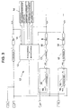
- the load output control system has a register block for determining the rotational torque distribution, whose input variables consist at least of the number "n" of the active drives, and the load capacity of the individual drive support rollers, wherein processing values are determined by the system-specific design of the strand guide, expressed in terms of the geometry data of the cast strand and that information about the state of wear of the drive support rollers and the current Anstell concept F and the current drive torque M serve as input variables.
- a setpoint value M is determined in the arithmetic block from the input variables and introduced in each case into a torque controller as an input variable.
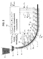
- the casting strand 1 (FIGS. 1 and 2) is produced in a continuous casting process, in which the liquid metal, in particular liquid steel material, is guided from the ladle 2 via an intermediate container 3, formed in the continuous casting mold 4 by cooling with a strand shell, transported out, and further cooled and pulled out.
- the drive support rollers 7c are provided with a drive 10 consisting of an electric motor 8 for rotating support rollers, as well as for a strand support roller segment 9 (of a set of slipping support rollers 7a) such motor 8 is provided individually for each drive support roller 7c.
- drive 10 and a hydraulic piston-cylinder unit 11 for employment of individual support rollers 7a and drive support rollers 7c is designated.
- a load balancing control 12 (FIG. 1), the sum of the drive torques M 1 -M n is formed by all active drives 10 and an average value is formed therefrom. This mean value is fed back to each drive 10 as the desired drive torque M setpoint n . Via one controller each (in the load balancing controller 12) an attempt is made to set the output drive torque of the respective drive to the desired value by changing the rotational speed n setpoint n of the respective drive 10.
- the manipulated variables are the speed setpoint or the torque setpoint.
- FIG. 2 provides a method for driving drive support rollers 7c of the continuous casting machine shown as an example of a continuous slab caster for liquid metals, in particular for liquid steel materials, which electrically guides the strand guide 7 for the casting strand 1 driven, individual drive support rollers 7c and form the hydraulically engageable strand support roller segments 9, wherein the load compensation control 12 for the drives 10 as a sum of the individual forces for casting speed, engine torque, engine speed and usual correction factors is assumed.
- the total driving torque is determined for all the drives 10 from the normal force of the driven drive support rollers 7c, transferred to each drive support roller 7c proportionately according to the local conditions, with a static basic adjustment of the torque distribution as a specific load capacity of each drive support roller 7c is used.
- the specific load capacity of a drive support roller 7c is determined from the geometry of the strand guide 7 (for example sheet system), the ferrostatic height (height difference of the liquid strand core to the casting level of the continuous casting mold 4) and / or the roll pitch 7b.
- the actual setting forces F 1 -F n of the piston-cylinder units 11 of a strand support roller segment 9 or a drive support roller 7 c and functional values of the casting format are fed back to the load balancing control 12.
- a dynamic factor results from the setting forces F 1 -F n of the individual torques and from the individual speeds n 1-n for the torque input for each drive 10 from the ratio of the current normal force of the drive support rollers 7c to the theoretical normal force.
- An additional correction factor can be used for the roller wear and the friction conditions between cast strand 1 and support rollers 7a or drive support rollers 7c be taken into account. Furthermore, an unweighted total factor formed from the specific load capacity, the dynamic factor and the additional correction factor can be taken into account. In this case, a weighted total factor with the ratio of the number of all active drives 10 to the sum of all unweighted factors of all active drives 10 by multiplication is formed from the unweighted total factor. and taken into account.
- a control loop is formed, to which the mean value of the rotational drive torques of all active drives 10 and the setpoint speed n Soll is supplied.
- the mean value is supplied in each case with the weighted overall factor to the controllers as a target value M Soll, which transfers it to a speed setpoint value n set.
- the drives 10 are taken into account for the averaging or summation of the rotational drive torques, which are suitable for the transmission of the rotary drive torque, ie are capable of transmission.
- the actual setting forces F 1 -F n of the piston-cylinder units 11 for the strand support roller segments 9 or the drive support rollers 7 c or the piston-cylinder units 11 of drive support rollers 7 c can be increased until the required rotational drive torque is transmitted.
- the load balancing control 12 (FIG. 3) has a computation block 13 for determining the torque distribution, whose input variables 14 (number of drives "n", values for the system-specific design of the strand guide 7, geometry data of the cast strand 1, state of wear of the drive support rollers 7c and the stop position). Forces F with actual value), wherein the load capacity of the individual drive support rollers 7c are taken into account. For the installation-specific design of the strand guide 7, the geometric data of the cast strand 1, processing values are provided. Information about the state of wear of the drive support rollers 7c as well as the actual setting forces F and the current drive torques M serve as input variables 14 as input variables 14. In the calculation block 13, the input variables are entered Setpoint M is determined and introduced in each case in a torque controller as an input variable 16. In addition, a speed controller 17 is connected to the torque controller 15 and a correction speed 18 for the electric motor 8 is transmitted to this.
Landscapes
- Engineering & Computer Science (AREA)
- Mechanical Engineering (AREA)
- Continuous Casting (AREA)
- Rolls And Other Rotary Bodies (AREA)
- Control Of Multiple Motors (AREA)
- Fluid-Pressure Circuits (AREA)
Description
- Die Erfindung betrifft ein Verfahren und eine Einrichtung zum Antreiben der Stützrollen einer Stranggießmaschine für flüssige Metalle, insbesondere für flüssige Stahlwerkstoffe, die eine Strangführung für den Gießstrang aus elektrisch angetriebenen einzelnen Stützrollen und / oder aus hydraulisch anstellbaren Stützrollensegmenten bilden, wobei eine Lastausgleichsregelung für die Antriebe als Summe aus den Funktionen von Gießgeschwindigkeit, Motordrehmoment, Motordrehzahl und üblicher Korrekturfaktoren eingesetzt wird und mit individueller Einstellung von Drehmoment und Drehzahl jedes Antriebs-Stützrollenmotors versehen ist.
- Die Strangführung für den Gießstrang, der im Knüppel-, Brammen- oder Dünnbrammen-, Vorprofil- oder Block-Format gegossen wird, dient gleichzeitig als Ausfördereinrichtung, die den Gießstrang aus der Stranggießkokille kommend durch die Strangführung gegen deren Widerstände auszieht. Die Strangführung besteht aus geschleppten (nicht angetriebenen) Stützrollen und einer Stützrolle gegenüberliegenden, angetriebenen Antriebsstützrollen. Die Antriebsstützrollen übertragen sowohl Führungs- als auch Strangförderkräfte in Zusammenwirken mit den geschleppten Stützrollen und werden mit definierter Anstellkraft gegen den Gießstrang gedrückt. Die Gesamtheit der Antriebsstützrollen überwindet die Ausziehwiderstände, denen der Strang auf seinem Weg durch die Strangführung unterworfen ist.
- Die Leistung dieser Antriebe wird im allgemeinen derart bemessen, dass einerseits bei jeder denkbaren Betriebssituation ein sicheres Ausfördem des Gießstranges gewährleistet ist, andererseits jedoch die Herstellkosten und Betriebskosten möglichst niedrig gehalten und die Antriebe nicht unnötig überdimensioniert werden.
- Es ist bekannt, die Antriebsmomente der einzelnen Antriebe auf den Gießstrang nach zwei unterschiedlichen Arten zu übertragen.
- Die erste Art sieht vor, die Antriebe von Hand abzugleichen und während des Betriebes sich selbst zu überlassen.
- Bei einer zweiten Art (vgl. Fig. 1 zum Stand der Technik) wird von allen aktiven Antrieben die Summe der Antriebsmomente ( M1 - Mn ) festgestellt und daraus ein Mittelwert gebildet. Dieser Mittelwert wird als Sollantriebsmoment an jeden Antrieb zurückgeführt. Über eine Lastausgleichsregelung wird versucht, durch Drehzahländerungen (nSoll-n) des jeweiligen Antriebs das abgegebene Antriebsmoment dieses Antriebs auf den Sollwert einzustellen.
- Beiden Arten der Regelung haftet der Nachteil an, dass die Zuordnung der Antriebsmomente nicht nach den tatsächlich übertragbaren Kräften bzw. Drehmomenten erfolgt. Die Folge davon ist, dass Antriebe, die aufgrund ihrer geringen Normalkraft, sei es durch Rollenverschleiß oder technologisch bedingt, nur ein kleineres Moment als das Sollmoment aufbringen können und somit permanent mit stark erhöhter Drehzahl drehen, wodurch die Antriebsrollen einem erhöhten Verschleiß unterliegen.
- Ein weiterer Nachteil besteht darin, dass bei Entstehen eines prozessbedingt kurzzeitig erhöhten Ausziehwiderstandes ein höheres Gesamtdrehmoment benötigt wird, bei den Antrieben, die mehr als das mittlere Drehmoment übertragen könnten, wird nur der Mittelwert des Gesamtdrehmomentes abgerufen, d.h. also diese Antriebe sind unterfordert , während andere Antriebe das geforderte Sollmoment aus den angegebenen Gründen nicht übertragen können. Dieser Vorgang kann zum Stillstand des Gießstranges führen, was einen Gießabbruch mit großen Schäden zur Folge hat.
- Aus der EP - B- 0 463 203 ist ein Führungsverfahren für die elektrischen Antriebe von Rollen einer Stranggießanlage bekannt, wobei der Gießstrang durch die angetriebenen Rollen, deren Antriebe über Regler einzeln geregelt sind, aus der Stranggießkokille abgezogen wird und wobei die Sollwertvorgabe für die Rollenantriebe, bspw. über die Drehzahlvorgabe, lastabhängig erfolgt. Hier soll ein Lastausgleich zwischen den einzelnen Rollenantrieben erfolgen. Das Verfahren berücksichtigt jedoch nicht betriebsbedingte Situationen und nicht einen Gesamtaufwand an Leistung, der eine Kontrolle der erfahrungsgemäß im Normalfall aufzubringenden Gesamtantriebskraft gestattet.
- Aus der JP 2003 033854 A (abstract) ist ein Verfahren bzw eine Einrichtung zum Antreiben der Stützrolle einer Stranggießmaschine für flüssige Metalle, bekannt, mit individueller Einstellung von Drehmoment und Drehzahl. Insofern entspricht die bekannte Ausbildung der eingangs bezeichneten Gattung.
- In der JP 11 151 558 A (abstract) ist das bekannte Verfahren bzw. die bekannte Einrichtung mit einer individuellen Einstellung von Drehmoment und Drehzahl jedes Antriebs-Stützrollenmotors versehen. Dabei können jedoch die Nachteile nicht beseitigt werden, dass Antriebe, die aufgrund ihrer geringen Normalkraft, sei es durch Rollenverschleiss oder technologisch bedingt, nur ein kleines Drehmoment als das Soll-Drehmoment aufbringen können und somit mit stark erhöhter Drehzahl drehen, wodurch die Antriebsrollen einem erhöhten Verschleiß unterliegen. Eine bekannte Drehmoment-Ausgleichs-Recheneinhit zum Einstellen des Lastmomentes jeder Treibrolle reicht daher nicht aus, um ein notwendiges Gesamtantriebsmoment zu ermitteln.
- Der Erfindung liegt die Aufgabe zugrunde, das im Normalfall aufzubringende Gesamtantriebsdrehmoment auf die Antriebe zu verteilen, wie es deren natürlichen Übertragbarkeit aufgrund der Normalkraft der jeweiligen Stützrolle und Antriebsstützrolle entspricht.
- Die gestellte Aufgabe wird erfindungsgemäß dadurch gelöst, dass ein Gesamtantriebsmoment für alle Antriebe aus der Normalkraft der angetriebenen Stützrollen ermittelt und auf jede Stützrolle anteilsmäßig übertragen wird, und dass eine statische Grundeinstellung der Drehmomentverteilung als spezifische Belastbarkeit jeder Antriebsstützrolle zugrunde gelegt wird. Dadurch wird einerseits ein unnötiges Durchdrehen der Antriebsstützrollen verhindert und andererseits ist gewährleistet, dass das maximal mögliche Antriebsmoment von den Antriebsrollen auch tatsächlich auf den Gießstrang übertragen werden kann. Außerdem wird dadurch der Rollenverschleiß erheblich vermindert. Das Verfahren lässt sich sowohl bei konventionellen Strang-Stützrollensegmenten mit separat anstellbarer Antriebsstützrolle, bei Stützrollensegmenten mit im Oberrahmen integrierter Antriebsrolle (Cyber-Link-Segmenten); bei reinem Antriebs mittels Treiberrollen, als auch bei Mischformen von Antriebsvarianten anwenden.
- Eine Ausgestaltung sieht vor, dass die spezifische Belastbarkeit einer Antriebsstützrolle aus der Geometrie der Strangführung, der ferrostatischen Höhe und / oder der Rollenteilung ermittelt wird.
- Eine Korrektur der eingestellten Werte erfolgt nach anderen Merkmalen dadurch, dass die aktuellen Anstellkräfte der Kolben-Zylinder-Einheiten eines Strang-Stützrollensegmentes oder einer Antriebsstützrolle und Funktionswerte des Gießformats auf die Lastausgleichsregelung rückgeführt werden.
- Aus diesen Korrekturwerten kann nach einer Weiterentwicklung ein dynamischer Faktor aus den Anstellkräften der einzelnen Drehmomente und aus den einzelnen Drehzahlen für die Drehmomentvorgabe für jeden Antrieb aus dem Verhältnis der aktuellen Normalkraft der Antriebsstützrolle zur theoretischen Normalkraft ergibt.
- Weiterhin kann ein zusätzlicher Korrekturfaktor für den Rollenverschleiß und die Reibverhältnisse zwischen Gießstrang und Stützrollen bzw. Antriebsstützrollen berücksichtigt werden. Dadurch wird ein weiteres Kriterium der bisherigen Abweichungen erfasst.
- Nach anderen Merkmalen lässt sich die Genauigkeit des Regelverfahrens dadurch erhöhen, dass ein aus der spezifischen Belastbarkeit, dem dynamischen Faktor und dem zusätzlichen Korrekturfaktor gebildeter ungewichteter Gesamtfaktor berücksichtigt wird.
- Eine andere Weiterentwicklung sieht vor, dass aus dem ungewichteten Gesamtfaktor ein gewichteter Gesamtfaktor mit dem Verhältnis aus der Anzahl aller aktiven Antriebe zur Summe aller ungewichteten Faktoren aller aktiven Antriebe durch Multiplikation gebildet und berücksichtigt wird.
- Weitere Merkmale bestehen darin, dass für jeden Antrieb ein Regelkreis vorgesehen ist, dem der Mittelwert der Drehäntriebsmömente aller aktiven Antriebe und der Sollwertdrehzahl zugeführt wird.
- Darauf aufbauend wird der Mittelwert jeweils mit dem gewichteten Gesamtfaktor den Reglern als Sollwert zugeführt, der diesen in einen Drehzahl-Stellwert überführt.
- Eine Besonderheit ist außerdem dadurch gegeben, dass für die Mittelwertbildung oder Summenbildung der Drehantriebsmomente nur die Antriebe berücksichtigt werden, die für die Übertragung des Drehantriebsmomentes geeignet sind.
- In Fällen, in denen die Prozess-Situation eine solche Maßnahme erlaubt, ist vorgesehen, dass die aktuellen Anstellkräfte der Kolben-Zylinder-Einheiten für die Strang-Stützrollensegmente oder der Antriebsstützrollen oder der Kolben-Zylinder-Einheiten von Antriebsstützrollen derart erhöht werden bis das geforderte Drehantriebsmoment übertragen wird.
- Eine Einrichtung zum Antreiben von Antriebsstützrollen einer Stranggießmaschine für flüssige Metalle, insbesondere für flüssige Stahlwerkstoffe, bildet nach dem Stand der Technik eine Strangführung für den Gießstrang aus elektrisch angetriebenen, einzelnen Antriebsstützrollen und 1 oder aus hydraulisch anstellbaren Strang-Stützrollensegmenten, wobei eine Lastausgleichsregelung für die Antriebe als Summe aus den Einzelkräften für Gießgeschwindigkeit, Motordrehmoment, Motordrehzahl und übliche Korrekturfaktoren ausgebildet ist und mit individueller Einstellung von Drehmoment und Drehzahl jedes Antriebs-Stützrollenmotors versehen ist.
- Die gestellte Aufgabe wird erfindungsgemäß dadurch gelöst, dass die Lastausgteicfrtsregelung einen Rechsnblock-zur Ermittlung der Drehfnomentverteiiung aüfweist, dessen Eingangsgrößen zumindest aus der Anzahl "n" der aktiven Antriebe, und der Belastbarkeit der einzelnen Antriebsstützrollen bestehen, wobei Verarbeitungswerte durch die anlagenspezifische Ausführung der Strangführung, der Geometriedaten des Gießstrangs ausgedrückt eingegeben werden und dass Informationen über den Verschleisszustand der Antriebsstützrollen sowie die aktuellen Anstellkräfte F und die aktuellen Antriebsmomente M als Eingangsgrößen dienen.
- In Ausgestaltung des Grundgedankens wird in dem Rechenblock aus den Eingangsgrößen ein Sollwert M ermittelt und jeweils in einen Drehmomentregler als Eingangsgröße eingeführt.
- Weitere Merkmale sind dahingehend vorgesehen, dass an den Drehmomentregler jeweils ein Drehzahlregler angeschlossen ist und an diesen eine Korrekturdrehzahl an den elektrischen Motor übertragen wird.
- In der Zeichnung ist ein Ausführungsbeispiel der Erfindung dargestellt, das nachstehend näher erläutert wird.
- Es zeigen:
- Fig. 1
- eine Gesamt-Seitenahsicht einer Stranggießanlage mit einer Lastausgleichsregelung gemäß dem derzeitigen Stand der Technik,
- Fig. 2
- dieselbe Gesamt-Seitenansicht der Stranggießanlage mit der erfindungsgemäßen Lastausgleichsregelung und
- Fig. 3
- ein Blockschaltbild der Lastausgleichsregelung.
- Der Gießstrang 1 (Fig. 1 und 2) entsteht im kontinuierlichen Gießverfahren, bei dem das flüssige Metall, insbesondere flüssiger Stahlwerkstoff, aus der Gießpfanne 2 über einen Zwischenbehälter 3 geführt, in der Stranggießkokille 4 durch Abkühlen mit einer Strangschale gebildet, austransportiert, weiter gekühlt und ausgezogen wird.
- Im Gegensatz zum Stand der Technik (Fig. 1) ist erfindungsgemäß (Fig. 2) eine Strangführung 7 für den Gießstrang 1 aus einem Segment (ohne Anstellung und ohne Antrieb der Stützrollen) nachfolgend aus Segmenten 6 mit schleppend mitlaufenden Stützrollen 7a bei entsprechender Rollenteilung 7b und unabhängig angestellten Antriebsstützrollen 7c gebildet. Die Antriebsstützrollen 7c sind mit einem Antrieb 10 versehen, der für drehende Stützrollen aus einem elektrischen Motor 8 besteht, wie auch für ein Strang-Stützrollensegment 9 (aus einem Satz von schleppenden Stützrollen 7a) ein solcher Motor 8 einzeln für jede Antriebsstützrolle 7c vorhanden ist. Als Antrieb 10 ist auch eine hydraulische Kolben-Zylinder-Einheit 11 zur Anstellung einzelner Stützrollen 7a und Antriebsstützrollen 7c bezeichnet.
- In einer Lastausgleichsregelung 12 (Fig. 1) wird von allen aktiven Antrieben 10 die Summe der Antriebsmomente M1- Mn gebildet und daraus ein Mittelwert gebildet. Dieser Mittelwert wird als Sollantriebsmoment M Soll n an jeden Antrieb 10 zurückgeführt. Über jeweils einen Regler (in der Lastausgleichsregelung 12) wird versucht, durch Drehzahländerungen n Soll n des jeweiligen Antriebs 10 das abgegebene Antriebsmoment des jeweiligen Antriebs auf den Sollwert einzustellen. Die Stellwerte sind der Drehzahlsollwert bzw. der Drehmomentsollwert.
- Im Gegensatz zum Stand der Technik (Fig. 1) ist in Fig 2 ein Verfahren zum Antreiben von Antriebsstützrollen 7c der gezeigten Stranggießmaschine als Beispiel für eine Brammenstranggießanlage für flüssige Metalle, insbesondere für flüssige Stahlwerkstoffe vorausgesetzt, die die Strangführung 7 für den Gießstrang 1 aus elektrisch angetriebenen, einzelnen Antriebsstützrollen 7c und aus den hydraulisch anstellbaren Strang-Stützrollensegmenten 9 bilden, wobei die Lastausgleichsregelung 12 für die Antriebe 10 als Summe aus den Einzelkräften für Gießgeschwindigkeit, Motordrehmoment, Motordrehzahl und übliche Korrekturfaktoren vorausgesetzt wird.
- Das Gesamtanfriebsmoment wird für alle Antriebe 10 aus der Normalkraft der angetriebenen Antriebsstützrollen 7c ermittelt, auf jede Antriebsstützrolle 7c anteilsmäßig nach den örtlichen Verhälfnissen übertragen, wobei eine statische Grundeinstellung der Drehmomentverteilung als spezifische Belastbarkeit jeder Antriebsstützrolle 7c zugrunde gelegt wird. Die spezifische Belastbarkeit einer Antriebsstützrolle 7c wird aus der Geometrie der Strangführung 7 (bspw. Bogenanlage), der ferrostatischen Höhe (Höhenunterschied des flüssigen Strangkerns bis zum Gießspiegel der Stranggießkokille 4) und / oder der Rollenteilung 7b ermittelt. Die aktuellen Anstellkräfte F1- Fn der Kolben-Zylinder-Einheiten 11 eines Strang-Stützrollensegmentes 9 oder einer Antriebsstützrolle 7c und Funktionswerte des Gießformates werden auf die Lastausgleichsregelung 12 rückgeführt. Ein dynamischer Faktor ergibt sich aus den Anstellkräften F1 - F n der einzelnen Drehmomente und aus den einzelnen Drehzahlen n 1-n für die Drehmomentvorgabe für jeden Antrieb 10 aus dem Verhältnis der aktuellen Normalkraft der Antriebsstützrollen 7c zur theoretischen Normalkraft.
- Ein zusätzlicher Korrekturfaktor kann für den Rollenverschleiß und die Reibverhältnisse zwischen Gießstrang 1 und Stützrollen 7a bzw. Antriebsstützrollen 7c berücksichtigt werden. Weiterhin kann ein aus der spezifischen Belastbarkeit, dem dynamischen Faktor und dem zusätzlichen Korrekturfaktor gebildeter, ungewichteter Gesamtfaktor berücksichtigt werden. Dabei wird aus dem ungewichteten Gesamtfaktor ein gewichteter Gesamtfaktor mit dem Verhältnis aus der Anzahl aller aktiven Antriebe 10 zur Summe aller ungewichteter Faktoren aller aktiven Antriebe 10 durch,Multiplikation gebildet. und berücksichtigt.
- Für jeden Antrieb 10 (Antriebsstützrollen 7c und / oder hydraulische Kolben-Zylinder-Einheit 11) ist ein Regelkreis gebildet, dem der Mittelwert der Drehantriebsmomente aller aktiven Antriebe 10 und der Sollwertdrehzahl n Soll zugeführt wird. Der Mittelwert wird jeweils mit dem gewichteten Gesamtfaktor den Reglern als Sollwert M Soll zugeführt, der diesen in einen Drehzahl-Sollwert n Soll überführt. Dabei werden für die Mittelwertbildung oder Summenbildung der Drehantriebsmomente nur die Antriebe 10 berücksichtigt, die für die Übertragung des Drehantriebsmomentes geeignet, d.h. übertragungsfähig sind.
- Ferner können die aktuellen Anstellkräfte F1- F n der Kolben-Zylinder-Einheiten 11 für die Strang-Stützrollensegmente 9 oder der Antriebsstützrollen 7c oder der Kolben-Zylinder-Einheiten 11 von Antriebsstützrollen 7c derart erhöht werden bis das geforderte Drehantriebsmoment übertragen wird.
- Die Lastausgleichsregelung 12 (Fig. 3) weist einen Rechenblock 13 zur Ermittlung der Drehmomentverteilung auf, dessen Eingangsgrößen 14 (Anzahl Antriebe "n", Werte für die anlagenspezifische Ausführung der Strangführung 7, Geometriedaten des Gießstrangs 1, Verschleisszustand der Antriebsstützrollen 7c und die Anstell- Kräfte F mit Istwert) umfasst, wobei auch die Belastbarkeit der einzelnen Antriebsstützrollen 7c berücksichtigt sind. Für die anlagenspezifische Ausführung der Strangführung 7, der Geometriedaten des Gießstrangs 1 sind Verarbeitungswerte vorgesehen. Als weitere Eingangsgrößen 14 dienen Informationen über den Verschleisszustand der Antriebsstützrollen 7c sowie die aktuellen Anstellkräfte F und die aktuellen Antriebsdrehmomente M als Eingangsgrößen 14. In dem Rechenblock 13 wird aus den Eingangsgrößen ein Sollwert M ermittelt und jeweils in einen Drehmomentregler als Eingangsgröße 16 eingeführt. Außerdem ist an den Drehmomentenregler 15 jeweils ein Drehzahlregler 17 angeschlossen und auf diesen wird eine Korrekturdrehzahl 18 für den elektrischen Motor 8 übertragen.
-
- 1
- Gießstrang
- 2
- Gießpfanne
- 3
- Zwischenbehälter
- 4
- Stranggießkokille
- 5
- Segment ohne Anstellung und ohne Antrieb
- 6
- Segment mit unabhängig angestellter Antriebsstützrolle
- 7
- Strangführung
- 7a
- Stützrollen, schleppend
- 7b
- Rollenteilung
- 7c
- Antriebsstützrollen
- 8
- elektrischer Motor
- 9
- Strang-Stützrollensegment
- 10
- Antrieb
- 11
- hydraulische Kolben-Zylinder-Einheit
- 12
- Lastausgleichsregelung
- 13
- Rechenblock
- 14
- Eingangsgröße
- 15
- Drehmomentenregler
- 16
- Eingangsgröße
- 17
- Drehzahlgeber
- 18
- Korrekturdrehzahl
Claims (14)
- Verfahren zum Antreiben der Stützrollen (7c) einer Stranggießmaschine für flüssige Metalle, insbesondere für flüssige Stahlwerkstoffe, die eine Strangführung (7) für den Gießstrang (1) aus elektrisch angetriebenen einzelnen Antriebsstützrollen (7c) und / oder aus hydraulisch anstellbaren Strang-Stützrollensegmenten (9) bilden, wobei eine Lastausgleichsregelung (12) für die Antriebe (10) als Summe aus den Einzelkräften für Gießgeschwindigkeit, Motordrehmoment, Motordrehzahl und übliche Korrekturfaktoren eingesetzt wird, und mit individueller Einstellung von Drehmoment und Drehzahl jedes Antriebs-Stützrollenmotors (8) versehen ist,
dadurch gekennzeichnet,
dass ein Gesamtantriebsmoment für alle Antriebe (10) aus der Normalkraft der angetriebenen Antriebsstützrollen (7c) derart ermittelt und auf jede Antriebsstützrolle (7c) anteilsmäßig übertragen wird, dass eine statische Grundeinstellung der Drehmomentverteilung als spezifische Belastbarkeit jeder Antriebsstützrolle (7c) zugrunde gelegt wird. - Verfahren nach Anspruch 1,
dadurch gekennzeichnet,
dass die spezifische Belastbarkeit einer Antriebsstützrolle (7c) aus der Geometrie der Strangführung (7), der ferrostatischen Höhe und / oder der Rollenteilung (7b) ermittelt wird. - Verfahren nach einem der Ansprüche 1 oder 2,
dadurch gekennzeichnet,
dass die aktuellen Anstellkräfte (F1 - Fn ) der Kolben-Zylinder-Einheiten (11) eines Strang-Stützrollensegmentes (9) oder einer Antriebsstützrolle (7c) und Funktionswerte des Gießformats auf die Lastausgleichsregelung (12) rückgeführt werden. - Verfahren nach Anspruch 3,
dadurch gekennzeichnet,
dass ein dynamischer Faktor aus den Anstellkräften (F1 - Fn) der einzelnen Drehmomente ( M 1-n) und aus den einzelnen Drehzahlen ( n 1-n) für die Drehmomentvorgabe für jeden Antrieb (10) aus dem Verhältnis der aktuellen Normalkraft der Antriebsstützrolle (7c) zur theoretischen Normalkraft ergibt. - Verfahren nach einem der Ansprüche 1 bis 4,
dadurch gekennzeichnet,
dass ein zusätzlicher Korrekturfaktor für den Rollenverschleiß- und die Reibverhältnisse zwischen Gießstrang (1) und Stützrollen (7a) bzw. Antriebsstützrolle (7c) berücksichtigt wird. - Verfahren nach einem der Ansprüche 1 bis 5,
dadurch gekennzeichnet,
dass ein aus der spezifischen Belastbarkeit, dem dynamischen Faktor und dem zusätzlichen Korrekturfaktor gebildeter ungewichteter Gesamtfaktor berücksichtigt wird. - Verfahren nach Anspruch 6.
dadurch gekennzeichnet,
dass aus dem ungewichteten Gesamtfaktor ein gewichteter Gesamtfaktor mit dem Verhältnis aus der Anzahl aller aktiven Antriebe (10) zur Summe aller ungewichteten Faktoren aller aktiven Antriebe (10) durch Multiplikation gebildet und berücksichtigt wird. - Verfahren nach einem der Ansprüche 1 bis 7,
dadurch gekennzeichnet,
dass für jeden Antrieb (10) ein Regelkreis vorgesehen ist, dem der Mittelwert der Drehantriebsmomente aller aktiven Antriebe (10) und der Sollwertdrehzahl (n Soll) zugeführt wird. - Verfahren nach den Ansprüchen 7 und 8,
dadurch gekennzeichnet,
dass der Mittelwert jeweils mit dem gewichteten Gesamtfaktor den Reglern als Sollwert ( M Soll) zugeführt wird, der diesen in einen Drehzahl-Stellwert ( n Soll) überführt. - Verfahren nach einem der Ansprüche 8 oder 9,
dadurch gekennzeichnet,
dass für die Mittelwertbildung oder Summenbildung der Drehantriebsmomente nur die Antriebe (10) berücksichtigt werden, die für die Übertragung des Drehantriebsmomentes geeignet sind. - Verfahren nach einem der Ansprüche 8 oder 9,
dadurch gekennzeichnet,
dass die aktuellen Anstellkräfte (F1 - Fn ) der Kolben-Zylinder-Einheiten (11) für die Strang-Stützrollensegmente (9) oder der Antriebsstützrollen (7c) oder der Kolben-Zylinder-Einheiten (11) von Antriebsstützrollen (7c) derart erhöht werden bis das geforderte Drehantriebsmoment übertragen wird. - Einrichtung zum Antreiben von Antriebsstützrollen (7c) einer Stranggießmaschine für flüssige Metalle, insbesondere für flüssige Stahlwerkstoffe, die eine Strangführung (7) für den Gießstrang (1) aus elektrisch angetriebenen, einzelnen Antriebsstützrollen (7c) und / oder aus hydraulisch anstellbaren Strang-Stützrollensegmenten (9) bilden, wobei eine Lastausgleichsregelung (12) für die Antriebe (10) als Summe aus den Einzelkräften für Gießgeschwindigkeit, Motordrehmoment, Motordrehzahl und übliche Korrekturfaktoren ausgebildet ist, und mit individueller Einstellung von Drehmoment und Drehzahl jedes Antriebs-Stützrollenmotors (8) versehen ist,
dadurch gekennzeichnet,
dass die Lastausgleichsregelung (12) einen Rechenblock (13) zur Ermittlung der Drehmomentverteilung aufweist, dessen Eingangsgrößen (14) zumindest aus der Anzahl "n" der aktiven Antriebe (8; 11) und der Belastbarkeit der einzelnen Antriebsstützrollen (7c) bestehen, wobei Verarbeitungswerte durch die anlagenspezifische Ausführung der Strangführung (7), der Geometriedaten des Gießstrangs (1) ausgedrückt eingegeben werden, und dass Informationen über den Verschleisszustand der Antriebsstützrollen (7c) sowie die aktuellen Anstellkräfte F1-n und die aktuellen Antriebsmomente M ist,1-n als Eingangsgrößen (14) dienen. - Einrichtung nach Anspruch 12,
dadurch gekennzeichnet,
dass in dem Rechenblock (13) aus den Eingangsgrößen (14) ein Sollwert M soll.1-n ermittelt und jeweils in einen Drehmomentregier (15) als Eingangsgröße (16) eingeführt wird. - Einrichtung nach den Ansprüchen 12 und 13,
dadurch gekennzeichnet,
dass an den Drehmomentregler (15) jeweils ein Drehzahlregler (17) angeschlossen ist und an diesen eine Korrekturdrehzahl (18) an den elektrischen Motor (8) übertragbar ist.
Applications Claiming Priority (2)
| Application Number | Priority Date | Filing Date | Title |
|---|---|---|---|
| DE102004010038A DE102004010038A1 (de) | 2004-03-02 | 2004-03-02 | Verfahren und Einrichtung zum Antreiben von Stützrollen einer Stranggießmaschine für flüssige Metalle, insbesondere für flüssige Stahlwerkstoffe |
| PCT/EP2005/000802 WO2005084841A1 (de) | 2004-03-02 | 2005-01-27 | Verfahren und einrichtung zum antreiben von stützrollen einer stranggiessmaschine für flüssige metalle, insbesondere für flüssige stahlwekstoffe |
Publications (2)
| Publication Number | Publication Date |
|---|---|
| EP1720669A1 EP1720669A1 (de) | 2006-11-15 |
| EP1720669B1 true EP1720669B1 (de) | 2007-05-09 |
Family
ID=34853880
Family Applications (1)
| Application Number | Title | Priority Date | Filing Date |
|---|---|---|---|
| EP05707040A Expired - Lifetime EP1720669B1 (de) | 2004-03-02 | 2005-01-27 | Verfahren und einrichtung zum antreiben von stützrollen einer stranggiessmaschine für flüssige metalle, insbesondere für flüssige stahlwerkstoffe |
Country Status (11)
| Country | Link |
|---|---|
| US (1) | US7762312B2 (de) |
| EP (1) | EP1720669B1 (de) |
| JP (1) | JP2007526128A (de) |
| KR (1) | KR20070005610A (de) |
| CN (1) | CN1925932B (de) |
| AT (1) | ATE361796T1 (de) |
| CA (1) | CA2558481C (de) |
| DE (2) | DE102004010038A1 (de) |
| ES (1) | ES2285678T3 (de) |
| RU (1) | RU2369460C2 (de) |
| WO (1) | WO2005084841A1 (de) |
Cited By (2)
| Publication number | Priority date | Publication date | Assignee | Title |
|---|---|---|---|---|
| US8497014B2 (en) | 2007-06-27 | 2013-07-30 | Pilkington Group Limited | Heat treatable coated glass pane |
| EP3000539A1 (de) | 2014-09-24 | 2016-03-30 | SMS group GmbH | Verfahren und Gieß-Walz-Anlage zum Gießen und Walzen eines endlosen Stranggutes |
Families Citing this family (5)
| Publication number | Priority date | Publication date | Assignee | Title |
|---|---|---|---|---|
| DE102004048618A1 (de) * | 2004-10-06 | 2006-04-13 | Sms Demag Ag | Verfahren und Rollensegment zum Bestimmen der Kernerstarrung und/oder der Sumpfspitze beim Stranggießen von Metallen, insbesondere von Stahlwerkstoffen |
| CN103192044A (zh) * | 2013-04-19 | 2013-07-10 | 中冶连铸技术工程股份有限公司 | 一种拉坯辊的传动负荷控制方法和装置 |
| CN113798460B (zh) * | 2021-09-01 | 2022-11-25 | 中冶南方连铸技术工程有限责任公司 | 拉矫机系统及拉矫机传动装置负载系数的调整方法 |
| CN116274916A (zh) * | 2021-12-20 | 2023-06-23 | 斯凯孚公司 | 用于钢坯连铸过程的实时监测方法和稳定性分析方法 |
| DE102022208499A1 (de) * | 2022-08-16 | 2024-02-22 | Sms Group Gmbh | Verfahren und Computerprogrammprodukt zum Betreiben einer Gieß-Walzanlage |
Family Cites Families (11)
| Publication number | Priority date | Publication date | Assignee | Title |
|---|---|---|---|---|
| US4090549A (en) * | 1974-07-12 | 1978-05-23 | United States Steel Corporation | Method and mechanism for determining forces on a solidifying casting |
| JPS55133855A (en) | 1979-04-06 | 1980-10-18 | Hitachi Ltd | Control method of continuous casting machine |
| JPS56126061A (en) | 1980-03-08 | 1981-10-02 | Yaskawa Electric Mfg Co Ltd | Control unit for ingot drawing device in continuous casting plant |
| JPS59225866A (ja) | 1983-06-07 | 1984-12-18 | Nippon Steel Corp | 連続鋳造設備における鋳片引抜制御装置 |
| JPS60227958A (ja) | 1984-12-06 | 1985-11-13 | Yaskawa Electric Mfg Co Ltd | 連続鋳造設備における鋳片引抜装置の制御方法 |
| JPS63154252A (ja) * | 1986-12-17 | 1988-06-27 | Kobe Steel Ltd | ピンチロ−ルの圧着検出方法 |
| DE3907905C2 (de) | 1988-07-04 | 1999-01-21 | Mannesmann Ag | Stranggießverfahren |
| IT1262116B (it) * | 1993-05-17 | 1996-06-19 | Danieli Off Mecc | Procedimento di prelaminazione controllata per bramme sottili uscenti da colata continua e dispositivo relativo |
| JPH07136751A (ja) | 1993-11-16 | 1995-05-30 | Kobe Steel Ltd | 連続鋳造設備における鋳片引抜ロールのトルクバランス制御方法 |
| JP3874220B2 (ja) * | 1997-11-21 | 2007-01-31 | 株式会社安川電機 | 連続鋳造設備のピンチロール速度制御装置 |
| JP4623619B2 (ja) * | 2001-07-18 | 2011-02-02 | 新日本製鐵株式会社 | 連続鋳造機の鋳片圧縮力制御装置 |
-
2004
- 2004-03-02 DE DE102004010038A patent/DE102004010038A1/de not_active Withdrawn
-
2005
- 2005-01-27 CN CN2005800068817A patent/CN1925932B/zh not_active Expired - Fee Related
- 2005-01-27 JP JP2007501136A patent/JP2007526128A/ja active Pending
- 2005-01-27 ES ES05707040T patent/ES2285678T3/es not_active Expired - Lifetime
- 2005-01-27 US US10/591,518 patent/US7762312B2/en not_active Expired - Fee Related
- 2005-01-27 WO PCT/EP2005/000802 patent/WO2005084841A1/de not_active Ceased
- 2005-01-27 AT AT05707040T patent/ATE361796T1/de active
- 2005-01-27 DE DE502005000710T patent/DE502005000710D1/de not_active Expired - Lifetime
- 2005-01-27 KR KR1020067017897A patent/KR20070005610A/ko not_active Ceased
- 2005-01-27 RU RU2006134625/02A patent/RU2369460C2/ru not_active IP Right Cessation
- 2005-01-27 EP EP05707040A patent/EP1720669B1/de not_active Expired - Lifetime
- 2005-01-27 CA CA2558481A patent/CA2558481C/en not_active Expired - Fee Related
Cited By (2)
| Publication number | Priority date | Publication date | Assignee | Title |
|---|---|---|---|---|
| US8497014B2 (en) | 2007-06-27 | 2013-07-30 | Pilkington Group Limited | Heat treatable coated glass pane |
| EP3000539A1 (de) | 2014-09-24 | 2016-03-30 | SMS group GmbH | Verfahren und Gieß-Walz-Anlage zum Gießen und Walzen eines endlosen Stranggutes |
Also Published As
| Publication number | Publication date |
|---|---|
| CN1925932A (zh) | 2007-03-07 |
| KR20070005610A (ko) | 2007-01-10 |
| DE502005000710D1 (de) | 2007-06-21 |
| RU2006134625A (ru) | 2008-04-10 |
| US7762312B2 (en) | 2010-07-27 |
| DE102004010038A1 (de) | 2005-09-15 |
| ATE361796T1 (de) | 2007-06-15 |
| WO2005084841A1 (de) | 2005-09-15 |
| JP2007526128A (ja) | 2007-09-13 |
| CA2558481C (en) | 2012-01-24 |
| CA2558481A1 (en) | 2005-09-15 |
| RU2369460C2 (ru) | 2009-10-10 |
| ES2285678T3 (es) | 2007-11-16 |
| EP1720669A1 (de) | 2006-11-15 |
| US20080035300A1 (en) | 2008-02-14 |
| CN1925932B (zh) | 2010-12-08 |
Similar Documents
| Publication | Publication Date | Title |
|---|---|---|
| EP0350431B2 (de) | Stranggiessverfahren für die Erzeugung von Brammen mit einer gegenüber dem Gusszustand verringerten Dicke | |
| DE3637893C2 (de) | Verfahren und Anlage zur Herstellung von warmgewalztem Stahlband und Bandgießanlage | |
| DE602004003734T2 (de) | Verfahren und Vorrichtung zur Dickenregelung eines gewalzten Produktes | |
| DE19809807C2 (de) | Anstellverfahren für ein Rollensegment einer Stranggießanlage | |
| DE60034273T2 (de) | Verfahren und Vorrichtung zum Giessen eines Metallstranges | |
| DE4321963A1 (de) | Verfahren zum Steuern eines Warmbandwalzwerks | |
| EP2346625A2 (de) | Verfahren zur einstellung einer auslaufdicke eines eine mehrgerüstige walzstrasse durchlaufenden walzguts, steuer- und/oder regeleinrichtung und walzanlage | |
| EP1720669B1 (de) | Verfahren und einrichtung zum antreiben von stützrollen einer stranggiessmaschine für flüssige metalle, insbesondere für flüssige stahlwerkstoffe | |
| EP1125657A2 (de) | Verfahren und Anlage zum Giessen von Vorprodukten in einer Stranggiessanlage | |
| DE1943556A1 (de) | Verfahren und Einrichtung zur Beeinflussung des Walzablaufs eines Walzgutes in einer Walzanlage | |
| DE3422762C2 (de) | ||
| DE69607781T2 (de) | Warmbandwalzanlage | |
| EP3917694B1 (de) | Verändern der effektiven kontur einer lauffläche einer arbeitswalze während des warmwalzens eines walzguts in einem walzgerüst zu einem gewalzten band | |
| DE69120819T2 (de) | Verfahren und vorrichtung zum giessen zwischen zwei walzen | |
| DE69623343T2 (de) | Walzwerk, walzverfahren und walzanlage | |
| DE3822939C1 (en) | Continuous casting method for the production of slabs with a reduced thickness relative to the cast condition | |
| EP2111314A1 (de) | Verfahren zur führung eines giessguts aus einem giessbehälter einer giessanlage und giessanlage zum giessen eines giessguts | |
| EP0036490B1 (de) | Verfahren und Antriebsanordnung zum Regeln der Einzelantriebe einer Bogenstranggiess-Vielrollenmaschine für Metall, insbesondere für Stahl | |
| EP0721811A1 (de) | Verfahren zur Regelung des Walzspaltprofils | |
| EP2268427B1 (de) | Betriebsverfahren für eine kaltwalzstrasse mit verbesserter dynamik | |
| EP2934779A1 (de) | Verfahren und vorrichtung zum wickeln eines metallbandes | |
| EP2869945B1 (de) | Kontinuierlich arbeitende bandgiess- und walzanlage | |
| DE19511801A1 (de) | Verfahren und Vorrichtung zur Dickenvorsteuerung beim Folienwalzen | |
| DE102010007660A1 (de) | Stranggießmaschine | |
| EP0463203B1 (de) | Führungsverfahren für die elektrischen Antriebe von Rollen einer Stranggiessanlage und Einrichtung zur Durchführung des Verfahrens |
Legal Events
| Date | Code | Title | Description |
|---|---|---|---|
| PUAI | Public reference made under article 153(3) epc to a published international application that has entered the european phase |
Free format text: ORIGINAL CODE: 0009012 |
|
| 17P | Request for examination filed |
Effective date: 20060803 |
|
| AK | Designated contracting states |
Kind code of ref document: A1 Designated state(s): AT BE BG CH CY CZ DE DK EE ES FI FR GB GR HU IE IS IT LI LT LU MC NL PL PT RO SE SI SK TR |
|
| GRAP | Despatch of communication of intention to grant a patent |
Free format text: ORIGINAL CODE: EPIDOSNIGR1 |
|
| GRAS | Grant fee paid |
Free format text: ORIGINAL CODE: EPIDOSNIGR3 |
|
| GRAA | (expected) grant |
Free format text: ORIGINAL CODE: 0009210 |
|
| AK | Designated contracting states |
Kind code of ref document: B1 Designated state(s): AT BE BG CH CY CZ DE DK EE ES FI FR GB GR HU IE IS IT LI LT LU MC NL PL PT RO SE SI SK TR |
|
| PG25 | Lapsed in a contracting state [announced via postgrant information from national office to epo] |
Ref country code: FI Free format text: LAPSE BECAUSE OF FAILURE TO SUBMIT A TRANSLATION OF THE DESCRIPTION OR TO PAY THE FEE WITHIN THE PRESCRIBED TIME-LIMIT Effective date: 20070509 |
|
| REG | Reference to a national code |
Ref country code: GB Ref legal event code: FG4D Free format text: NOT ENGLISH |
|
| REG | Reference to a national code |
Ref country code: CH Ref legal event code: EP |
|
| REG | Reference to a national code |
Ref country code: IE Ref legal event code: FG4D Free format text: LANGUAGE OF EP DOCUMENT: GERMAN |
|
| REF | Corresponds to: |
Ref document number: 502005000710 Country of ref document: DE Date of ref document: 20070621 Kind code of ref document: P |
|
| PG25 | Lapsed in a contracting state [announced via postgrant information from national office to epo] |
Ref country code: SE Free format text: LAPSE BECAUSE OF FAILURE TO SUBMIT A TRANSLATION OF THE DESCRIPTION OR TO PAY THE FEE WITHIN THE PRESCRIBED TIME-LIMIT Effective date: 20070809 |
|
| PG25 | Lapsed in a contracting state [announced via postgrant information from national office to epo] |
Ref country code: IS Free format text: LAPSE BECAUSE OF FAILURE TO SUBMIT A TRANSLATION OF THE DESCRIPTION OR TO PAY THE FEE WITHIN THE PRESCRIBED TIME-LIMIT Effective date: 20070909 |
|
| GBT | Gb: translation of ep patent filed (gb section 77(6)(a)/1977) |
Effective date: 20070822 |
|
| NLV1 | Nl: lapsed or annulled due to failure to fulfill the requirements of art. 29p and 29m of the patents act | ||
| REG | Reference to a national code |
Ref country code: ES Ref legal event code: FG2A Ref document number: 2285678 Country of ref document: ES Kind code of ref document: T3 |
|
| PG25 | Lapsed in a contracting state [announced via postgrant information from national office to epo] |
Ref country code: PL Free format text: LAPSE BECAUSE OF FAILURE TO SUBMIT A TRANSLATION OF THE DESCRIPTION OR TO PAY THE FEE WITHIN THE PRESCRIBED TIME-LIMIT Effective date: 20070509 |
|
| REG | Reference to a national code |
Ref country code: IE Ref legal event code: FD4D |
|
| EN | Fr: translation not filed | ||
| PG25 | Lapsed in a contracting state [announced via postgrant information from national office to epo] |
Ref country code: IE Free format text: LAPSE BECAUSE OF FAILURE TO SUBMIT A TRANSLATION OF THE DESCRIPTION OR TO PAY THE FEE WITHIN THE PRESCRIBED TIME-LIMIT Effective date: 20070509 Ref country code: NL Free format text: LAPSE BECAUSE OF FAILURE TO SUBMIT A TRANSLATION OF THE DESCRIPTION OR TO PAY THE FEE WITHIN THE PRESCRIBED TIME-LIMIT Effective date: 20070509 Ref country code: SI Free format text: LAPSE BECAUSE OF FAILURE TO SUBMIT A TRANSLATION OF THE DESCRIPTION OR TO PAY THE FEE WITHIN THE PRESCRIBED TIME-LIMIT Effective date: 20070509 Ref country code: PT Free format text: LAPSE BECAUSE OF FAILURE TO SUBMIT A TRANSLATION OF THE DESCRIPTION OR TO PAY THE FEE WITHIN THE PRESCRIBED TIME-LIMIT Effective date: 20071009 Ref country code: DK Free format text: LAPSE BECAUSE OF FAILURE TO SUBMIT A TRANSLATION OF THE DESCRIPTION OR TO PAY THE FEE WITHIN THE PRESCRIBED TIME-LIMIT Effective date: 20070509 Ref country code: CZ Free format text: LAPSE BECAUSE OF FAILURE TO SUBMIT A TRANSLATION OF THE DESCRIPTION OR TO PAY THE FEE WITHIN THE PRESCRIBED TIME-LIMIT Effective date: 20070509 Ref country code: BG Free format text: LAPSE BECAUSE OF FAILURE TO SUBMIT A TRANSLATION OF THE DESCRIPTION OR TO PAY THE FEE WITHIN THE PRESCRIBED TIME-LIMIT Effective date: 20070809 |
|
| PG25 | Lapsed in a contracting state [announced via postgrant information from national office to epo] |
Ref country code: SK Free format text: LAPSE BECAUSE OF FAILURE TO SUBMIT A TRANSLATION OF THE DESCRIPTION OR TO PAY THE FEE WITHIN THE PRESCRIBED TIME-LIMIT Effective date: 20070509 Ref country code: LT Free format text: LAPSE BECAUSE OF FAILURE TO SUBMIT A TRANSLATION OF THE DESCRIPTION OR TO PAY THE FEE WITHIN THE PRESCRIBED TIME-LIMIT Effective date: 20070509 |
|
| PLBE | No opposition filed within time limit |
Free format text: ORIGINAL CODE: 0009261 |
|
| STAA | Information on the status of an ep patent application or granted ep patent |
Free format text: STATUS: NO OPPOSITION FILED WITHIN TIME LIMIT |
|
| 26N | No opposition filed |
Effective date: 20080212 |
|
| PG25 | Lapsed in a contracting state [announced via postgrant information from national office to epo] |
Ref country code: GR Free format text: LAPSE BECAUSE OF FAILURE TO SUBMIT A TRANSLATION OF THE DESCRIPTION OR TO PAY THE FEE WITHIN THE PRESCRIBED TIME-LIMIT Effective date: 20070810 |
|
| PG25 | Lapsed in a contracting state [announced via postgrant information from national office to epo] |
Ref country code: RO Free format text: LAPSE BECAUSE OF FAILURE TO SUBMIT A TRANSLATION OF THE DESCRIPTION OR TO PAY THE FEE WITHIN THE PRESCRIBED TIME-LIMIT Effective date: 20070509 |
|
| BERE | Be: lapsed |
Owner name: MS DEMAG AG Effective date: 20080131 |
|
| PG25 | Lapsed in a contracting state [announced via postgrant information from national office to epo] |
Ref country code: FR Free format text: LAPSE BECAUSE OF FAILURE TO SUBMIT A TRANSLATION OF THE DESCRIPTION OR TO PAY THE FEE WITHIN THE PRESCRIBED TIME-LIMIT Effective date: 20080104 |
|
| PG25 | Lapsed in a contracting state [announced via postgrant information from national office to epo] |
Ref country code: MC Free format text: LAPSE BECAUSE OF NON-PAYMENT OF DUE FEES Effective date: 20080131 |
|
| PG25 | Lapsed in a contracting state [announced via postgrant information from national office to epo] |
Ref country code: EE Free format text: LAPSE BECAUSE OF FAILURE TO SUBMIT A TRANSLATION OF THE DESCRIPTION OR TO PAY THE FEE WITHIN THE PRESCRIBED TIME-LIMIT Effective date: 20070509 |
|
| PG25 | Lapsed in a contracting state [announced via postgrant information from national office to epo] |
Ref country code: BE Free format text: LAPSE BECAUSE OF NON-PAYMENT OF DUE FEES Effective date: 20080131 |
|
| PG25 | Lapsed in a contracting state [announced via postgrant information from national office to epo] |
Ref country code: CY Free format text: LAPSE BECAUSE OF FAILURE TO SUBMIT A TRANSLATION OF THE DESCRIPTION OR TO PAY THE FEE WITHIN THE PRESCRIBED TIME-LIMIT Effective date: 20070509 |
|
| REG | Reference to a national code |
Ref country code: CH Ref legal event code: PL |
|
| PG25 | Lapsed in a contracting state [announced via postgrant information from national office to epo] |
Ref country code: LI Free format text: LAPSE BECAUSE OF NON-PAYMENT OF DUE FEES Effective date: 20090131 Ref country code: CH Free format text: LAPSE BECAUSE OF NON-PAYMENT OF DUE FEES Effective date: 20090131 |
|
| PGFP | Annual fee paid to national office [announced via postgrant information from national office to epo] |
Ref country code: ES Payment date: 20100125 Year of fee payment: 6 |
|
| PG25 | Lapsed in a contracting state [announced via postgrant information from national office to epo] |
Ref country code: LU Free format text: LAPSE BECAUSE OF NON-PAYMENT OF DUE FEES Effective date: 20080127 Ref country code: HU Free format text: LAPSE BECAUSE OF FAILURE TO SUBMIT A TRANSLATION OF THE DESCRIPTION OR TO PAY THE FEE WITHIN THE PRESCRIBED TIME-LIMIT Effective date: 20071110 |
|
| PG25 | Lapsed in a contracting state [announced via postgrant information from national office to epo] |
Ref country code: TR Free format text: LAPSE BECAUSE OF FAILURE TO SUBMIT A TRANSLATION OF THE DESCRIPTION OR TO PAY THE FEE WITHIN THE PRESCRIBED TIME-LIMIT Effective date: 20070509 |
|
| REG | Reference to a national code |
Ref country code: ES Ref legal event code: FD2A Effective date: 20120220 |
|
| PG25 | Lapsed in a contracting state [announced via postgrant information from national office to epo] |
Ref country code: ES Free format text: LAPSE BECAUSE OF NON-PAYMENT OF DUE FEES Effective date: 20110128 |
|
| PGFP | Annual fee paid to national office [announced via postgrant information from national office to epo] |
Ref country code: GB Payment date: 20130122 Year of fee payment: 9 |
|
| GBPC | Gb: european patent ceased through non-payment of renewal fee |
Effective date: 20140127 |
|
| PG25 | Lapsed in a contracting state [announced via postgrant information from national office to epo] |
Ref country code: GB Free format text: LAPSE BECAUSE OF NON-PAYMENT OF DUE FEES Effective date: 20140127 |
|
| REG | Reference to a national code |
Ref country code: DE Ref legal event code: R082 Ref document number: 502005000710 Country of ref document: DE Representative=s name: HEMMERICH & KOLLEGEN, DE Ref country code: DE Ref legal event code: R081 Ref document number: 502005000710 Country of ref document: DE Owner name: SMS GROUP GMBH, DE Free format text: FORMER OWNER: SMS SIEMAG AKTIENGESELLSCHAFT, 40237 DUESSELDORF, DE |
|
| P01 | Opt-out of the competence of the unified patent court (upc) registered |
Effective date: 20230707 |
|
| PGFP | Annual fee paid to national office [announced via postgrant information from national office to epo] |
Ref country code: AT Payment date: 20240122 Year of fee payment: 20 |
|
| PGFP | Annual fee paid to national office [announced via postgrant information from national office to epo] |
Ref country code: DE Payment date: 20240119 Year of fee payment: 20 |
|
| PGFP | Annual fee paid to national office [announced via postgrant information from national office to epo] |
Ref country code: IT Payment date: 20240129 Year of fee payment: 20 |
|
| REG | Reference to a national code |
Ref country code: DE Ref legal event code: R071 Ref document number: 502005000710 Country of ref document: DE |
|
| REG | Reference to a national code |
Ref country code: AT Ref legal event code: MK07 Ref document number: 361796 Country of ref document: AT Kind code of ref document: T Effective date: 20250127 |