EP2998541B1 - Fuel injection spray patterns for opposed-piston engines - Google Patents
Fuel injection spray patterns for opposed-piston engines Download PDFInfo
- Publication number
- EP2998541B1 EP2998541B1 EP15192839.7A EP15192839A EP2998541B1 EP 2998541 B1 EP2998541 B1 EP 2998541B1 EP 15192839 A EP15192839 A EP 15192839A EP 2998541 B1 EP2998541 B1 EP 2998541B1
- Authority
- EP
- European Patent Office
- Prior art keywords
- pistons
- combustion chamber
- bore
- cylinder
- fuel
- Prior art date
- Legal status (The legal status is an assumption and is not a legal conclusion. Google has not performed a legal analysis and makes no representation as to the accuracy of the status listed.)
- Active
Links
- 239000000446 fuel Substances 0.000 title claims description 50
- 239000007921 spray Substances 0.000 title claims description 46
- 238000002347 injection Methods 0.000 title claims description 28
- 239000007924 injection Substances 0.000 title claims description 28
- 238000002485 combustion reaction Methods 0.000 claims description 79
- 238000000034 method Methods 0.000 claims description 9
- 239000003570 air Substances 0.000 description 51
- 238000010276 construction Methods 0.000 description 17
- 239000000203 mixture Substances 0.000 description 6
- 230000000295 complement effect Effects 0.000 description 5
- 239000007789 gas Substances 0.000 description 5
- 230000003993 interaction Effects 0.000 description 5
- 230000006835 compression Effects 0.000 description 3
- 238000007906 compression Methods 0.000 description 3
- 238000010586 diagram Methods 0.000 description 3
- 230000000694 effects Effects 0.000 description 2
- 230000002000 scavenging effect Effects 0.000 description 2
- 229910001018 Cast iron Inorganic materials 0.000 description 1
- 229910000677 High-carbon steel Inorganic materials 0.000 description 1
- 229910052782 aluminium Inorganic materials 0.000 description 1
- XAGFODPZIPBFFR-UHFFFAOYSA-N aluminium Chemical compound [Al] XAGFODPZIPBFFR-UHFFFAOYSA-N 0.000 description 1
- 239000012080 ambient air Substances 0.000 description 1
- QVGXLLKOCUKJST-UHFFFAOYSA-N atomic oxygen Chemical compound [O] QVGXLLKOCUKJST-UHFFFAOYSA-N 0.000 description 1
- 238000005266 casting Methods 0.000 description 1
- 239000002283 diesel fuel Substances 0.000 description 1
- 239000003085 diluting agent Substances 0.000 description 1
- 238000003754 machining Methods 0.000 description 1
- 238000004519 manufacturing process Methods 0.000 description 1
- 239000000463 material Substances 0.000 description 1
- 230000007246 mechanism Effects 0.000 description 1
- 239000007769 metal material Substances 0.000 description 1
- 230000000116 mitigating effect Effects 0.000 description 1
- 229910052760 oxygen Inorganic materials 0.000 description 1
- 239000001301 oxygen Substances 0.000 description 1
- 230000008569 process Effects 0.000 description 1
- 230000004044 response Effects 0.000 description 1
- 239000004071 soot Substances 0.000 description 1
- 238000009834 vaporization Methods 0.000 description 1
- 230000008016 vaporization Effects 0.000 description 1
- 239000013598 vector Substances 0.000 description 1
Images


Classifications
-
- F—MECHANICAL ENGINEERING; LIGHTING; HEATING; WEAPONS; BLASTING
- F01—MACHINES OR ENGINES IN GENERAL; ENGINE PLANTS IN GENERAL; STEAM ENGINES
- F01B—MACHINES OR ENGINES, IN GENERAL OR OF POSITIVE-DISPLACEMENT TYPE, e.g. STEAM ENGINES
- F01B7/00—Machines or engines with two or more pistons reciprocating within same cylinder or within essentially coaxial cylinders
- F01B7/02—Machines or engines with two or more pistons reciprocating within same cylinder or within essentially coaxial cylinders with oppositely reciprocating pistons
- F01B7/04—Machines or engines with two or more pistons reciprocating within same cylinder or within essentially coaxial cylinders with oppositely reciprocating pistons acting on same main shaft
- F01B7/06—Machines or engines with two or more pistons reciprocating within same cylinder or within essentially coaxial cylinders with oppositely reciprocating pistons acting on same main shaft using only connecting-rods for conversion of reciprocatory into rotary motion or vice versa
- F01B7/08—Machines or engines with two or more pistons reciprocating within same cylinder or within essentially coaxial cylinders with oppositely reciprocating pistons acting on same main shaft using only connecting-rods for conversion of reciprocatory into rotary motion or vice versa with side rods
-
- F—MECHANICAL ENGINEERING; LIGHTING; HEATING; WEAPONS; BLASTING
- F01—MACHINES OR ENGINES IN GENERAL; ENGINE PLANTS IN GENERAL; STEAM ENGINES
- F01B—MACHINES OR ENGINES, IN GENERAL OR OF POSITIVE-DISPLACEMENT TYPE, e.g. STEAM ENGINES
- F01B7/00—Machines or engines with two or more pistons reciprocating within same cylinder or within essentially coaxial cylinders
- F01B7/02—Machines or engines with two or more pistons reciprocating within same cylinder or within essentially coaxial cylinders with oppositely reciprocating pistons
- F01B7/04—Machines or engines with two or more pistons reciprocating within same cylinder or within essentially coaxial cylinders with oppositely reciprocating pistons acting on same main shaft
- F01B7/12—Machines or engines with two or more pistons reciprocating within same cylinder or within essentially coaxial cylinders with oppositely reciprocating pistons acting on same main shaft using rockers and connecting-rods
-
- F—MECHANICAL ENGINEERING; LIGHTING; HEATING; WEAPONS; BLASTING
- F02—COMBUSTION ENGINES; HOT-GAS OR COMBUSTION-PRODUCT ENGINE PLANTS
- F02B—INTERNAL-COMBUSTION PISTON ENGINES; COMBUSTION ENGINES IN GENERAL
- F02B23/00—Other engines characterised by special shape or construction of combustion chambers to improve operation
- F02B23/02—Other engines characterised by special shape or construction of combustion chambers to improve operation with compression ignition
- F02B23/06—Other engines characterised by special shape or construction of combustion chambers to improve operation with compression ignition the combustion space being arranged in working piston
- F02B23/0618—Other engines characterised by special shape or construction of combustion chambers to improve operation with compression ignition the combustion space being arranged in working piston having in-cylinder means to influence the charge motion
- F02B23/0621—Squish flow
-
- F—MECHANICAL ENGINEERING; LIGHTING; HEATING; WEAPONS; BLASTING
- F02—COMBUSTION ENGINES; HOT-GAS OR COMBUSTION-PRODUCT ENGINE PLANTS
- F02B—INTERNAL-COMBUSTION PISTON ENGINES; COMBUSTION ENGINES IN GENERAL
- F02B23/00—Other engines characterised by special shape or construction of combustion chambers to improve operation
- F02B23/02—Other engines characterised by special shape or construction of combustion chambers to improve operation with compression ignition
- F02B23/06—Other engines characterised by special shape or construction of combustion chambers to improve operation with compression ignition the combustion space being arranged in working piston
- F02B23/0618—Other engines characterised by special shape or construction of combustion chambers to improve operation with compression ignition the combustion space being arranged in working piston having in-cylinder means to influence the charge motion
- F02B23/0624—Swirl flow
-
- F—MECHANICAL ENGINEERING; LIGHTING; HEATING; WEAPONS; BLASTING
- F02—COMBUSTION ENGINES; HOT-GAS OR COMBUSTION-PRODUCT ENGINE PLANTS
- F02B—INTERNAL-COMBUSTION PISTON ENGINES; COMBUSTION ENGINES IN GENERAL
- F02B23/00—Other engines characterised by special shape or construction of combustion chambers to improve operation
- F02B23/02—Other engines characterised by special shape or construction of combustion chambers to improve operation with compression ignition
- F02B23/06—Other engines characterised by special shape or construction of combustion chambers to improve operation with compression ignition the combustion space being arranged in working piston
- F02B23/0618—Other engines characterised by special shape or construction of combustion chambers to improve operation with compression ignition the combustion space being arranged in working piston having in-cylinder means to influence the charge motion
- F02B23/063—Other engines characterised by special shape or construction of combustion chambers to improve operation with compression ignition the combustion space being arranged in working piston having in-cylinder means to influence the charge motion the combustion space in the piston interacting fluid dynamically with the cylinder head, the injector body or the cylinder wall
-
- F—MECHANICAL ENGINEERING; LIGHTING; HEATING; WEAPONS; BLASTING
- F02—COMBUSTION ENGINES; HOT-GAS OR COMBUSTION-PRODUCT ENGINE PLANTS
- F02B—INTERNAL-COMBUSTION PISTON ENGINES; COMBUSTION ENGINES IN GENERAL
- F02B23/00—Other engines characterised by special shape or construction of combustion chambers to improve operation
- F02B23/02—Other engines characterised by special shape or construction of combustion chambers to improve operation with compression ignition
- F02B23/06—Other engines characterised by special shape or construction of combustion chambers to improve operation with compression ignition the combustion space being arranged in working piston
- F02B23/0633—Other engines characterised by special shape or construction of combustion chambers to improve operation with compression ignition the combustion space being arranged in working piston the combustion space being almost completely enclosed in the piston, i.e. having a small inlet in comparison to its volume
-
- F—MECHANICAL ENGINEERING; LIGHTING; HEATING; WEAPONS; BLASTING
- F02—COMBUSTION ENGINES; HOT-GAS OR COMBUSTION-PRODUCT ENGINE PLANTS
- F02B—INTERNAL-COMBUSTION PISTON ENGINES; COMBUSTION ENGINES IN GENERAL
- F02B23/00—Other engines characterised by special shape or construction of combustion chambers to improve operation
- F02B23/02—Other engines characterised by special shape or construction of combustion chambers to improve operation with compression ignition
- F02B23/06—Other engines characterised by special shape or construction of combustion chambers to improve operation with compression ignition the combustion space being arranged in working piston
- F02B23/0645—Details related to the fuel injector or the fuel spray
- F02B23/0648—Means or methods to improve the spray dispersion, evaporation or ignition
- F02B23/0651—Means or methods to improve the spray dispersion, evaporation or ignition the fuel spray impinging on reflecting surfaces or being specially guided throughout the combustion space
-
- F—MECHANICAL ENGINEERING; LIGHTING; HEATING; WEAPONS; BLASTING
- F02—COMBUSTION ENGINES; HOT-GAS OR COMBUSTION-PRODUCT ENGINE PLANTS
- F02B—INTERNAL-COMBUSTION PISTON ENGINES; COMBUSTION ENGINES IN GENERAL
- F02B23/00—Other engines characterised by special shape or construction of combustion chambers to improve operation
- F02B23/02—Other engines characterised by special shape or construction of combustion chambers to improve operation with compression ignition
- F02B23/06—Other engines characterised by special shape or construction of combustion chambers to improve operation with compression ignition the combustion space being arranged in working piston
- F02B23/0645—Details related to the fuel injector or the fuel spray
- F02B23/0663—Details related to the fuel injector or the fuel spray having multiple injectors per combustion chamber
-
- F—MECHANICAL ENGINEERING; LIGHTING; HEATING; WEAPONS; BLASTING
- F02—COMBUSTION ENGINES; HOT-GAS OR COMBUSTION-PRODUCT ENGINE PLANTS
- F02B—INTERNAL-COMBUSTION PISTON ENGINES; COMBUSTION ENGINES IN GENERAL
- F02B23/00—Other engines characterised by special shape or construction of combustion chambers to improve operation
- F02B23/02—Other engines characterised by special shape or construction of combustion chambers to improve operation with compression ignition
- F02B23/06—Other engines characterised by special shape or construction of combustion chambers to improve operation with compression ignition the combustion space being arranged in working piston
- F02B23/0675—Other engines characterised by special shape or construction of combustion chambers to improve operation with compression ignition the combustion space being arranged in working piston the combustion space being substantially spherical, hemispherical, ellipsoid or parabolic
-
- F—MECHANICAL ENGINEERING; LIGHTING; HEATING; WEAPONS; BLASTING
- F02—COMBUSTION ENGINES; HOT-GAS OR COMBUSTION-PRODUCT ENGINE PLANTS
- F02B—INTERNAL-COMBUSTION PISTON ENGINES; COMBUSTION ENGINES IN GENERAL
- F02B23/00—Other engines characterised by special shape or construction of combustion chambers to improve operation
- F02B23/02—Other engines characterised by special shape or construction of combustion chambers to improve operation with compression ignition
- F02B23/06—Other engines characterised by special shape or construction of combustion chambers to improve operation with compression ignition the combustion space being arranged in working piston
- F02B23/0678—Unconventional, complex or non-rotationally symmetrical shapes of the combustion space, e.g. flower like, having special shapes related to the orientation of the fuel spray jets
-
- F—MECHANICAL ENGINEERING; LIGHTING; HEATING; WEAPONS; BLASTING
- F02—COMBUSTION ENGINES; HOT-GAS OR COMBUSTION-PRODUCT ENGINE PLANTS
- F02B—INTERNAL-COMBUSTION PISTON ENGINES; COMBUSTION ENGINES IN GENERAL
- F02B75/00—Other engines
- F02B75/04—Engines with variable distances between pistons at top dead-centre positions and cylinder heads
-
- F—MECHANICAL ENGINEERING; LIGHTING; HEATING; WEAPONS; BLASTING
- F02—COMBUSTION ENGINES; HOT-GAS OR COMBUSTION-PRODUCT ENGINE PLANTS
- F02B—INTERNAL-COMBUSTION PISTON ENGINES; COMBUSTION ENGINES IN GENERAL
- F02B75/00—Other engines
- F02B75/28—Engines with two or more pistons reciprocating within same cylinder or within essentially coaxial cylinders
- F02B75/282—Engines with two or more pistons reciprocating within same cylinder or within essentially coaxial cylinders the pistons having equal strokes
-
- F—MECHANICAL ENGINEERING; LIGHTING; HEATING; WEAPONS; BLASTING
- F02—COMBUSTION ENGINES; HOT-GAS OR COMBUSTION-PRODUCT ENGINE PLANTS
- F02B—INTERNAL-COMBUSTION PISTON ENGINES; COMBUSTION ENGINES IN GENERAL
- F02B75/00—Other engines
- F02B75/32—Engines characterised by connections between pistons and main shafts and not specific to preceding main groups
-
- F—MECHANICAL ENGINEERING; LIGHTING; HEATING; WEAPONS; BLASTING
- F02—COMBUSTION ENGINES; HOT-GAS OR COMBUSTION-PRODUCT ENGINE PLANTS
- F02M—SUPPLYING COMBUSTION ENGINES IN GENERAL WITH COMBUSTIBLE MIXTURES OR CONSTITUENTS THEREOF
- F02M61/00—Fuel-injectors not provided for in groups F02M39/00 - F02M57/00 or F02M67/00
- F02M61/14—Arrangements of injectors with respect to engines; Mounting of injectors
-
- F—MECHANICAL ENGINEERING; LIGHTING; HEATING; WEAPONS; BLASTING
- F16—ENGINEERING ELEMENTS AND UNITS; GENERAL MEASURES FOR PRODUCING AND MAINTAINING EFFECTIVE FUNCTIONING OF MACHINES OR INSTALLATIONS; THERMAL INSULATION IN GENERAL
- F16C—SHAFTS; FLEXIBLE SHAFTS; ELEMENTS OR CRANKSHAFT MECHANISMS; ROTARY BODIES OTHER THAN GEARING ELEMENTS; BEARINGS
- F16C33/00—Parts of bearings; Special methods for making bearings or parts thereof
- F16C33/02—Parts of sliding-contact bearings
- F16C33/04—Brasses; Bushes; Linings
-
- F—MECHANICAL ENGINEERING; LIGHTING; HEATING; WEAPONS; BLASTING
- F02—COMBUSTION ENGINES; HOT-GAS OR COMBUSTION-PRODUCT ENGINE PLANTS
- F02B—INTERNAL-COMBUSTION PISTON ENGINES; COMBUSTION ENGINES IN GENERAL
- F02B2275/00—Other engines, components or details, not provided for in other groups of this subclass
- F02B2275/48—Tumble motion in gas movement in cylinder
-
- F—MECHANICAL ENGINEERING; LIGHTING; HEATING; WEAPONS; BLASTING
- F02—COMBUSTION ENGINES; HOT-GAS OR COMBUSTION-PRODUCT ENGINE PLANTS
- F02M—SUPPLYING COMBUSTION ENGINES IN GENERAL WITH COMBUSTIBLE MIXTURES OR CONSTITUENTS THEREOF
- F02M61/00—Fuel-injectors not provided for in groups F02M39/00 - F02M57/00 or F02M67/00
- F02M61/16—Details not provided for in, or of interest apart from, the apparatus of groups F02M61/02 - F02M61/14
- F02M61/18—Injection nozzles, e.g. having valve seats; Details of valve member seated ends, not otherwise provided for
- F02M61/1806—Injection nozzles, e.g. having valve seats; Details of valve member seated ends, not otherwise provided for characterised by the arrangement of discharge orifices, e.g. orientation or size
-
- Y—GENERAL TAGGING OF NEW TECHNOLOGICAL DEVELOPMENTS; GENERAL TAGGING OF CROSS-SECTIONAL TECHNOLOGIES SPANNING OVER SEVERAL SECTIONS OF THE IPC; TECHNICAL SUBJECTS COVERED BY FORMER USPC CROSS-REFERENCE ART COLLECTIONS [XRACs] AND DIGESTS
- Y02—TECHNOLOGIES OR APPLICATIONS FOR MITIGATION OR ADAPTATION AGAINST CLIMATE CHANGE
- Y02T—CLIMATE CHANGE MITIGATION TECHNOLOGIES RELATED TO TRANSPORTATION
- Y02T10/00—Road transport of goods or passengers
- Y02T10/10—Internal combustion engine [ICE] based vehicles
- Y02T10/12—Improving ICE efficiencies
Definitions
- the field is combustion chambers for internal combustion engines.
- the field includes constructions for opposed-piston engines in which a combustion chamber is defined between end surfaces of pistons disposed in opposition in the bore of a ported cylinder.
- the field includes opposed-piston engines with combustion chamber constructions that produce a tumbling motion in charge air admitted into the cylinder between the piston end surfaces.
- Opposing spray patterns of fuel are injected into the combustion chamber.
- the opposing spray patterns are injected along a major axis of the combustion chamber.
- an opposed-piston engine includes at least one cylinder 10 with a bore 12 and longitudinally-displaced intake and exhaust ports 14 and 16 machined or formed therein.
- One or more fuel injectors 17 are secured in injector ports (ports where injectors are positioned) that open through the side surface of the cylinder.
- Two pistons 20, 22 according to the prior art are disposed in the bore 12 with their end surfaces 20e, 22e in opposition to each other.
- the piston 20 is denominated as the "intake” piston because of its proximity to the intake port 14.
- the piston 22 is denominated as the "exhaust" piston because of its proximity to the exhaust port 16.
- an opposed-piston engine with one or more ported cylinders such as the cylinder 10
- the opposed pistons in response to combustion the opposed pistons move away from respective top dead center (TDC) positions where they are at their innermost positions in the cylinder 10.
- TDC top dead center
- BDC bottom dead center
- the pistons may move in phase so that the intake and exhaust ports 14, 16 open and close in unison.
- one piston may lead the other in phase, in which case the intake and exhaust ports have different opening and closing times.
- a phase offset is introduced into the piston movements.
- the exhaust piston leads the intake piston and the phase offset causes the pistons to move around their BDC positions in a sequence in which the exhaust port 16 opens as the exhaust piston 22 moves through BDC while the intake port 14 is still closed so that combustion gasses start to flow out of the exhaust port 16.
- the intake piston 20 moves through BDC causing the intake port 14 to open while the exhaust port 16 is still open.
- a charge of pressurized air is forced into the cylinder 10 through the open intake port 14, driving exhaust gasses out of the cylinder through the exhaust port 16. As seen in FIG.
- the exhaust port 16 closes before the intake port 14 while the intake piston 20 continues to move away from BDC.
- the charge of fresh air is swirled as it passes through ramped openings of the intake port 14.
- the swirling motion (or simply, "swirl") 30 is a generally helical movement of charge air that circulates around the cylinder's longitudinal axis and moves longitudinally through the bore of the cylinder 10.
- the intake port 14 is closed and the swirling charge air remaining in the cylinder is compressed between the end surfaces 20e and 22e.
- fuel 40 is directly injected through the side of the cylinder ("direct side injection") into the compressed charge air 30 in the bore, between the end surfaces 20e, 22e of the pistons.
- direct side injection the swirling mixture of air and fuel is increasingly compressed in a combustion chamber 32 defined between the end surfaces 20e and 22e as the pistons 20 and 22 move through their respective TDC locations.
- the fuel ignites in the combustion chamber, driving the pistons apart toward their respective BDC locations.
- Turbulence is a desirable feature of charge air motion as fuel injection begins. Turbulence encourages the mixing of charge air with fuel for more complete and more uniform ignition than would otherwise occur.
- the geometries of the intake port openings and the cylinder of an opposed-piston engine provide a very effective platform for generation of a strong swirling motion of the charge air that promotes both removal of exhaust gasses (scavenging) and charge air turbulence.
- charge air motion that is dominated by swirl can produce undesirable effects during combustion. For example, during combustion in a cylindrical combustion chamber defined between flat piston end surfaces, swirl pushes the flame toward the cylinder bore, causing heat loss to the (relatively) cooler cylinder wall.
- turbulence is produced by squish flow from the periphery of the combustion chamber in a radial direction of the cylinder toward the cylinder's axis.
- Squish flow is generated by movement of compressed air from a relatively high-pressure region at the peripheries of the piston end surfaces to a lower-pressure region generated by a bowl formed in at least one piston end surface.
- Squish flow promotes charge air turbulence in the combustion chamber.
- US patent 6,170,443 discloses a cylinder with a pair of opposed pistons having complementary end surface constructions. A circular concave depression formed in one end surface is symmetrical with respect to the axis of its piston and rises to a point in its center.
- the periphery of the opposing end surface has a convex shape in the center of which a semi-toroidal (half donut- shaped) trench is formed.
- TDC the pistons approach TDC, they define a generally toroidally-shaped combustion chamber centered on the longitudinal axis of the cylinder.
- the combustion chamber is surrounded by a circumferential squish band defined between the concave and convex surface shapes.
- the squish band generates an inwardly-directed squish flow into the toroidal trench and creates "a swirl of high intensity near top dead center.” See the '443 patent at column 19, lines 25-27.
- Fuel is injected into the toroidal combustion chamber in a radial direction of the bore.
- tumble is a rotating movement of charge air that circulates in a direction that is transverse to the longitudinal axis of the cylinder.
- the tumbling motion is a circulation of charge air that circulates around a diameter of the cylinder bore.
- This additional element produces even more turbulence of the charge air, and thereby achieves better air/fuel mixing than can be obtained with swirl or squish alone.
- WO 0248524 A1 describes a two-stroke opposed piston internal combustion engine, with all the pistons connected to a common central crankshaft.
- the inboard pistons of each cylinder are connected to the crankshaft with pushrods and the outboard pistons are connected to the crankshaft with pullrods.
- This configuration results in a compact engine with a very low profile, in which the free mass forces can be essentially totally balanced.
- the engine configuration also allows for asymmetrical timing of the intake and exhaust ports through independent angular positioning of the eccentrics on the crankshaft, making the engine suitable for supercharging.
- the present invention provides a method for operating an internal combustion engine according to independent claim 1.
- the tumbling motion is a circulation of charge air that circulates around a diameter of the cylinder bore.
- opposing spray patterns of fuel injected into such a combustion chamber include multi-plume patterns that meet at or near the center of the combustion chamber.
- an internal combustion engine includes at least one cylinder with longitudinally-separated exhaust and intake ports; see, for example, the cylinder 10 illustrated in FIGS. 1 and 2 .
- a pair of pistons is disposed in opposition in a bore of the cylinder and a combustion chamber structure is defined between the opposing end surfaces of the pistons as the pistons move toward top dead center positions.
- a circumferential area defines a periphery on each of the end surfaces.
- the combustion chamber includes a cavity defined between the end surfaces, and has opposing openings through which fuel is injected (hereinafter an "injection ports") that extend at least generally in a diametrical direction of the cylinder and open into the cavity.
- one or more squish zones direct flows of compressed air (called “squish flows”) into the combustion chamber in at least one direction that is skewed with respect to a diametrical direction of the bore. This process is referred to as "generating squish”.
- the portions of the end surfaces that generate squish are referred to as squish surfaces, and channels defined between the squish surfaces are referred to as squish channels.
- Squish flow is deflected or redirected by one or more curved surfaces in a combustion chamber cavity into at least one tumble motion that circulates in the cavity.
- fuel is any fuel that can be used in an opposed-piston engine.
- the fuel may be a relatively homogeneous composition, or a blend.
- the fuel may be diesel fuel or any other fuel ignitable by compression ignition.
- the descriptions contemplate ignition resulting from compression of an air/fuel mixture; however it may be desirable to provide additional mechanisms, such as glow plugs, to assist compression ignition.
- the descriptions contemplate injection of fuel into a compressed gas in a combustion chamber when opposed pistons are at or near TDC locations.
- the gas is preferably pressurized ambient air; however, it may include other components such as exhaust gases or other diluents. In any such case, the gas is referred to as "charge air.”
- FIGS. 13-6, 7A , 7B , and 8 illustrate a combustion chamber construction defined by complementary end surface structures of opposed pistons disposed in a ported cylinder of an opposed piston engine.
- Identical generally symmetrical bowls are formed in the end surfaces of the opposed pistons, and the pistons are rotationally oriented to place complementary curved surfaces of the bowls in opposition in order to maximize the squish surface areas of the squish zone.
- each piston has a periphery surrounding a bowl defining a concave surface.
- the concave surface includes a first portion curving away from a plane containing the periphery surface toward the interior of the piston and a second portion curving away from the first portion and protruding outwardly in part from the plane.
- a convex surface opposite the bowl curves away from the periphery and protrudes outwardly from the plane.
- the convex surface meets the second portion of the concave surface to form a ridge therewith.
- the bowl has a semi-ellipsoidal shape.
- the end surface structure is provided on both pistons and the pistons are disposed in the bore of a ported cylinder with their end surfaces oriented to place complementary curved surfaces of the end surface structures in opposition in order to define a combustion chambers.
- the combustion chamber space defined between these two end surfaces is, or is very close to, an elongated ellipsoidal cylinder, providing a generally symmetrical geometry to reinforce and sustain the tumble motion.
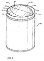
- the structures of the piston end surfaces that define the combustion chamber construction are essentially identical to each other; accordingly, the piston 280 shown in FIG. 3 represents both the intake piston and exhaust piston.
- the piston 280 has an end surface 282.
- a flat circumferential area 284 centered on the longitudinal axis of the piston 280 defines a periphery of the end surface 282.
- a bowl 286 is formed within the periphery.
- the bowl 286 has a concave surface 288 with a first portion 290 curving inwardly from a plane containing the flat circumferential area 284, toward the interior of the piston 280, and a second portion 292 curving outwardly from the interior of the piston through the plane.
- the end surface 282 further includes a convex surface 295 within the periphery that curves outwardly from the plane.
- the convex surface 295 meets the second portion 292 of the concave surface 288 to form a ridge 296 that protrudes outwardly from the end surface 282.
- At least one notch 294 extends through the periphery into the bowl 286; preferably two aligned notches 294 are provided.
- the two pistons 280 having end surfaces shaped as per FIG. 3 are shown at or near respective BDC locations within the ported cylinder 220.
- the pistons are rotationally oriented in the bore of the cylinder 220 so as to align the end surfaces in complement; that is to say, the concave surface portion 290 of one piston 280 faces the convex surface 295 of the other piston.
- Charge air is forced through the intake port 224 into the cylinder, as exhaust products flow out of the cylinder through the exhaust port 226. For purposes of scavenging and air/fuel mixing, the charge air is caused to swirl as it passes through the intake port 224.
- the pistons 280 move from BDC toward TDC as per FIG.
- the opposing concave-convex surfaces 290, 295 mesh with one another to give the combustion chamber cavity an elongated, generally ellipsoidal shape.
- Opposing pairs of notches 294 (see FIG. 3 ) in the end surfaces 282 define injection ports 303 (see FIG. 7A ) that open into the combustion chamber 300 at opposing pole positions of the ellipsoidal shape.
- the elongated, ellipsoidal shape has a major axis 302 that extends between the opposing pole positions. In other words, the injection ports 303 are aligned along the major axis 302.
- FIGS. 9A and 9B Interactions between the end surfaces 282 and charge air are illustrated in FIGS. 9A and 9B.
- FIG. 9A shows squish flows into the combustion chamber 300 without charge air swirl
- FIG. 9B illustrates how the squish flows affect and are affected by swirl.
- squish regions between opposing concave-convex surface pairs 290, 295 produce locally high pressure that directs squish flows of charge air into the central region of the combustion chamber 300.
- the concave-convex surface pairs 290, 295 generate squish flows 341, 342 into the combustion chamber 300.
- a tumbling motion is a circulating motion of charge air in the combustion chamber that is at least generally transverse to the longitudinal axis of the cylinder; in the case of the tumbling motion 343, the circulation is generally around the major axis 302. As per FIG.
- the turbulent motion of the charge air in the combustion chamber 300 includes a swirl component, incoming squish flows, and tumble components about orthogonal tumble axes.
- fuel 248 is injected into the tumbling air in the combustion chamber space 300 by opposed injectors 250.
- the combustion chamber is essentially centered with respect to the longitudinal axes of the cylinder and the pistons.
- the pairs of aligned notches 294 define injection ports 303 opening into the combustion chamber cavity 300.
- the injection ports 303 are located at or near respective ends of the combustion chamber, aligned with the major axis 302 thereof, and fuel is injected from two opposing injectors 250 through the injection ports so that the fuel 248 is confined between and guided by the opposing concave surface portions 292.
- the view is a sectional one at or near the longitudinal midpoint of the cylinder 220, looking directly into the cylinder's bore 221 toward a piston end surface 282 disposed in the bore at a position where it and the unseen piston end surface define the combustion chamber 300.
- the cylinder's axis is indicated by reference numeral 223.
- the combustion chamber 300 is essentially centered longitudinally with respect to the cylinder's axis 223.
- Fuel injectors 250 are positioned with their nozzle tips 251 disposed at injector ports 265.
- Each injector nozzle tip has one or more holes through which fuel 248 is injected through a respective injector port, into the combustion chamber 300.
- each injector tip 251 sprays fuel 248 in a diverging pattern that is aligned with and travels through an injection port 303 along the major axis 302 of the ellipsoidal combustion chamber 300, into the central portion of the combustion chamber 300.
- opposing spray patterns of fuel are injected into the turbulent air motion in the combustion chamber 300.
- the opposing spray patterns travel toward the center of the combustion chamber and form a cloud of fuel droplets that are mixed with charge air having a complex turbulent motion that includes swirl, squish, and tumble components.
- the fuel injectors 250 are disposed such that their axes A are in alignment with each other and a diametrical direction of the bore 221. This causes the injector tips to be oriented in opposition along a diameter of the cylinder 220 that is aligned with the major axis 302.
- Fuel spray patterns In order to amplify the advantages gained with a combustion chamber such as is described and illustrated above, it is desirable to provide fuel spray patterns that further enhance fuel vaporization and air/fuel mixing in the complex, turbulent charge air motion produced by those combustion chambers.
- the fuel spray patterns can be provided with one or more plumes, depending upon design and performance goal. However, spray patterns with multiple plumes are preferred because they expose the injected fuel quantity to a larger portion of oxygen in the combustion chamber, and lead to less fuel-rich regions and lower soot production.
- the fuel spray patterns are produced by injectors that are mounted for opposing direct side injection and that include nozzles in which the holes are placed to independently project respective plumes of a spray pattern.
- FIGS. 10A , 10B, and 10C illustrate opposing fuel spray patterns, however, these patterns are meant only to be representative of opposing spray patterns that are injected into the combustion chamber 300.
- a single representative spray pattern 381 is shown in FIG. 10A , so as to be able to see properties common to both patterns.
- the spray pattern 381 includes a plurality of plumes 383 distributed in an arrangement referenced to an injection axis 385; in this regard, the plumes are arcuately spaced with respect to each other, and are inclined with respect to the injection axis 385.
- the precise configuration of a spray pattern is determined according to design and/or performance requirements. Accordingly, it is within the scope of this description to vary one or more of the following parameters in the specifications of opposing spray patterns: the number of plumes, the arcuate spacing between the plumes, the angles of inclination, and the relationship of the injection axes.
- each spray pattern has a generally conical configuration defined by four plumes 383 that are arcuately spaced at 90°, with each plume 383 inclined at an angle in a range of 10°-30° with respect to the injection axis 385; for example, all of the plumes are inclined at 20° with respect to the injection axis 385.
- the injection axes 385 of the two opposing spray patterns are aligned with respective opposing radial directions of the cylinder bore; that is to say the axes are aligned along a diameter of the bore.
- the opposing spray patterns are rotationally aligned so that the plumes are oriented in opposition near the center of the bore; in another example, shown in FIG. 10C , the opposing spray patterns are mutually rotationally offset so that the plumes are interdigitated.
- the fuel injectors 250 can be configured and/or positioned so as to provide opposing spray patterns having any rotational relationship between the two alignments seen in FIGS. 10B and 10C .
- the opposing four-plume spray patterns can be rotationally offset in a range of 0°-45°, such that, when the rotational offset of the spray patterns is 0° ( FIG.
- the plumes of one spray pattern are in opposition with corresponding plumes of the opposing spray pattern, and, when the rotational offset of the spray patterns is 45° ( FIG. 10C ), the plumes of one spray pattern are interdigitated with the plumes of the opposing spray pattern.
- combustion chamber construction illustrated and described hereinabove is intended to be utilized in opposed-piston combustion-ignition engines which impose swirl on the charge of air forced into the cylinder.- Nevertheless, the combustion chamber construction can be utilized in those opposed-piston combustion-ignition engines that do not swirl the charge air.
- the pistons and associated cylinder are manufactured by casting and/or machining metal materials.
- the pistons may be constituted of a skirt assembled to a crown on which a piston end surface is formed.
- the- crown may comprise a high carbon steel such as 41 -40 or 43-40, and the skirt may be formed using 4032-T651 aluminum.
- the cylinder preferably, but not necessarily, comprises a cast iron composition.
Description
- The field is combustion chambers for internal combustion engines. In particular, the field includes constructions for opposed-piston engines in which a combustion chamber is defined between end surfaces of pistons disposed in opposition in the bore of a ported cylinder. More particularly, the field includes opposed-piston engines with combustion chamber constructions that produce a tumbling motion in charge air admitted into the cylinder between the piston end surfaces. Opposing spray patterns of fuel are injected into the combustion chamber. In some aspects, the opposing spray patterns are injected along a major axis of the combustion chamber.
- Per
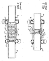
FIG. 1 , an opposed-piston engine includes at least onecylinder 10 with abore 12 and longitudinally-displaced intake andexhaust ports more fuel injectors 17 are secured in injector ports (ports where injectors are positioned) that open through the side surface of the cylinder. Twopistons bore 12 with theirend surfaces piston 20 is denominated as the "intake" piston because of its proximity to theintake port 14. Similarly, thepiston 22 is denominated as the "exhaust" piston because of its proximity to theexhaust port 16. - Operation of an opposed-piston engine with one or more ported cylinders (cylinders with one or more of intake and exhaust ports formed therein) such as the
cylinder 10 is well understood. In this regard, in response to combustion the opposed pistons move away from respective top dead center (TDC) positions where they are at their innermost positions in thecylinder 10. While moving from TDC, the pistons keep their associated ports closed until they approach respective bottom dead center (BDC) positions where they are at their outermost positions in the cylinder. The pistons may move in phase so that the intake andexhaust ports - In many opposed piston constructions, a phase offset is introduced into the piston movements. For example, the exhaust piston leads the intake piston and the phase offset causes the pistons to move around their BDC positions in a sequence in which the
exhaust port 16 opens as theexhaust piston 22 moves through BDC while theintake port 14 is still closed so that combustion gasses start to flow out of theexhaust port 16. As the pistons continue moving away from each other, theintake piston 20 moves through BDC causing theintake port 14 to open while theexhaust port 16 is still open. A charge of pressurized air is forced into thecylinder 10 through theopen intake port 14, driving exhaust gasses out of the cylinder through theexhaust port 16. As seen inFIG. 1 , after further movement of the pistons, theexhaust port 16 closes before theintake port 14 while theintake piston 20 continues to move away from BDC. Typically, the charge of fresh air is swirled as it passes through ramped openings of theintake port 14. With reference toFIG. 1 , the swirling motion (or simply, "swirl") 30 is a generally helical movement of charge air that circulates around the cylinder's longitudinal axis and moves longitudinally through the bore of thecylinder 10. PerFIG. 2 , as thepistons intake port 14 is closed and the swirling charge air remaining in the cylinder is compressed between theend surfaces fuel 40 is directly injected through the side of the cylinder ("direct side injection") into thecompressed charge air 30 in the bore, between theend surfaces combustion chamber 32 defined between theend surfaces pistons - Turbulence is a desirable feature of charge air motion as fuel injection begins. Turbulence encourages the mixing of charge air with fuel for more complete and more uniform ignition than would otherwise occur. The geometries of the intake port openings and the cylinder of an opposed-piston engine provide a very effective platform for generation of a strong swirling motion of the charge air that promotes both removal of exhaust gasses (scavenging) and charge air turbulence. However, charge air motion that is dominated by swirl can produce undesirable effects during combustion. For example, during combustion in a cylindrical combustion chamber defined between flat piston end surfaces, swirl pushes the flame toward the cylinder bore, causing heat loss to the (relatively) cooler cylinder wall. The higher velocity vectors of swirl occur near the cylinder wall, which provides the worst scenario for heat losses: high temperature gas with velocity that transfers heat to the cylinder wall and lowers the thermal efficiency of the engine. Accordingly, in such opposed-piston engines, it is desirable to maintain charge air turbulence as injection starts while mitigating the undesirable effects produced by swirl.
- In certain opposed-piston combustion chamber constructions, turbulence is produced by squish flow from the periphery of the combustion chamber in a radial direction of the cylinder toward the cylinder's axis. Squish flow is generated by movement of compressed air from a relatively high-pressure region at the peripheries of the piston end surfaces to a lower-pressure region generated by a bowl formed in at least one piston end surface. Squish flow promotes charge air turbulence in the combustion chamber. For example,
US patent 6,170,443 discloses a cylinder with a pair of opposed pistons having complementary end surface constructions. A circular concave depression formed in one end surface is symmetrical with respect to the axis of its piston and rises to a point in its center. The periphery of the opposing end surface has a convex shape in the center of which a semi-toroidal (half donut- shaped) trench is formed. As the pistons approach TDC, they define a generally toroidally-shaped combustion chamber centered on the longitudinal axis of the cylinder. The combustion chamber is surrounded by a circumferential squish band defined between the concave and convex surface shapes. As the pistons approach TDC, the squish band generates an inwardly-directed squish flow into the toroidal trench and creates "a swirl of high intensity near top dead center." See the '443 patent at column 19, lines 25-27. Fuel is injected into the toroidal combustion chamber in a radial direction of the bore. - Increasing the turbulence of charge air in the combustion chamber increases the effectiveness of air/fuel mixing. Domination of charge air motion by swirl or squish flow alone does achieve a certain level of turbulence. Accordingly, combustion chamber constructions for opposed-piston engines have been proposed that generate a tumble movement in charge air motion. See, for example, the combustion chambers described in commonly-owned
US patent application 13/066,589 -
WO 0248524 A1 - The relevant state of the art is also represented by
FR 50349 E US 2006/157003 A1 ,GB 562,343 A US 6,182,619 B1 ,US 2008/006,238 A1 ,US 2008/115771 A1 ,US 4 872 433 A . - The present invention provides a method for operating an internal combustion engine according to independent claim 1.
- Preferably, the tumbling motion is a circulation of charge air that circulates around a diameter of the cylinder bore.
- In some aspects, opposing spray patterns of fuel injected into such a combustion chamber include multi-plume patterns that meet at or near the center of the combustion chamber.
-
-
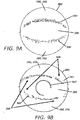
FIG. 1 is a side sectional partially schematic drawing of a cylinder of an opposed-piston engine with prior art opposed pistons near respective bottom dead center locations, and is appropriately labeled "Prior Art". -
FIG. 2 is a side sectional partially schematic drawing of the cylinder ofFIG. 1 with the prior art opposed pistons near respective top dead center locations where flat end surfaces of the pistons define a prior art combustion chamber, and is appropriately labeled "Prior Art". -
FIG. 3 is an elevational perspective view of a piston of a pair of pistons in which identical end surfaces of the pair of pistons are formed to define a combustion chamber construction. -
FIGS. 4-6 are side sectional drawings showing an operational sequence of an opposed-piston engine including a pair of pistons according toFIG. 3 . -
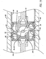
FIG. 7A is an enlarged view of a portion ofFIG. 6 showing in greater detail the combustion chamber construction. -
FIG. 7B is the enlarged view ofFIG. 7A showing squish and tumble air flows in the combustion chamber construction -
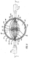
FIG. 8 is an end view of one of the pistons ofFIG. 3 showing an end surface with a bowl formed therein and a pattern of fuel injection. -
FIGS. 9A and 9B are schematic illustrations of the piston end surface view ofFIG. 8 showing interaction between the end surface and squish flow, without swirl (FIG. 9A ), and with swirl (FIG. 9B ). -
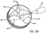
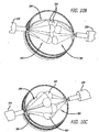
FIGS. 10A is an explanatory diagram for describing a fuel injection spray pattern with multiple plumes.FIG. 10B is an explanatory diagram for describing a first embodiment of a fuel injection spray pattern with multiple plumes.FIG. 10C is an explanatory diagram for describing a second embodiment of a fuel injection spray pattern with multiple plumes - In the combustion chamber construction to be described, an internal combustion engine includes at least one cylinder with longitudinally-separated exhaust and intake ports; see, for example, the
cylinder 10 illustrated inFIGS. 1 and 2 . A pair of pistons is disposed in opposition in a bore of the cylinder and a combustion chamber structure is defined between the opposing end surfaces of the pistons as the pistons move toward top dead center positions. A circumferential area defines a periphery on each of the end surfaces. The combustion chamber includes a cavity defined between the end surfaces, and has opposing openings through which fuel is injected (hereinafter an "injection ports") that extend at least generally in a diametrical direction of the cylinder and open into the cavity. - During operation of the internal combustion engine, as the pistons approach TDC, one or more squish zones direct flows of compressed air (called "squish flows") into the combustion chamber in at least one direction that is skewed with respect to a diametrical direction of the bore. This process is referred to as "generating squish". The portions of the end surfaces that generate squish are referred to as squish surfaces, and channels defined between the squish surfaces are referred to as squish channels. Squish flow is deflected or redirected by one or more curved surfaces in a combustion chamber cavity into at least one tumble motion that circulates in the cavity.
- In the following description, "fuel" is any fuel that can be used in an opposed-piston engine. The fuel may be a relatively homogeneous composition, or a blend. For example, the fuel may be diesel fuel or any other fuel ignitable by compression ignition. Further, the descriptions contemplate ignition resulting from compression of an air/fuel mixture; however it may be desirable to provide additional mechanisms, such as glow plugs, to assist compression ignition. The descriptions contemplate injection of fuel into a compressed gas in a combustion chamber when opposed pistons are at or near TDC locations. The gas is preferably pressurized ambient air; however, it may include other components such as exhaust gases or other diluents. In any such case, the gas is referred to as "charge air."
- Combustion chamber construction: FIGS. 13-6,
7A ,7B , and8 illustrate a combustion chamber construction defined by complementary end surface structures of opposed pistons disposed in a ported cylinder of an opposed piston engine. Identical generally symmetrical bowls are formed in the end surfaces of the opposed pistons, and the pistons are rotationally oriented to place complementary curved surfaces of the bowls in opposition in order to maximize the squish surface areas of the squish zone. - The end surface structure of each piston has a periphery surrounding a bowl defining a concave surface. The concave surface includes a first portion curving away from a plane containing the periphery surface toward the interior of the piston and a second portion curving away from the first portion and protruding outwardly in part from the plane. A convex surface opposite the bowl curves away from the periphery and protrudes outwardly from the plane. The convex surface meets the second portion of the concave surface to form a ridge therewith. According to the invention, the bowl has a semi-ellipsoidal shape. The end surface structure is provided on both pistons and the pistons are disposed in the bore of a ported cylinder with their end surfaces oriented to place complementary curved surfaces of the end surface structures in opposition in order to define a combustion chambers. According to the invention, the combustion chamber space defined between these two end surfaces is, or is very close to, an elongated ellipsoidal cylinder, providing a generally symmetrical geometry to reinforce and sustain the tumble motion. In this construction, it is desirable that a pair of injection ports be positioned in opposition on the major axis of the combustion chamber.
- The structures of the piston end surfaces that define the combustion chamber construction are essentially identical to each other; accordingly, the
piston 280 shown inFIG. 3 represents both the intake piston and exhaust piston. Thepiston 280 has anend surface 282. A flatcircumferential area 284 centered on the longitudinal axis of thepiston 280 defines a periphery of theend surface 282. Abowl 286 is formed within the periphery. Thebowl 286 has aconcave surface 288 with afirst portion 290 curving inwardly from a plane containing the flatcircumferential area 284, toward the interior of thepiston 280, and asecond portion 292 curving outwardly from the interior of the piston through the plane.<'> Theend surface 282 further includes aconvex surface 295 within the periphery that curves outwardly from the plane. Theconvex surface 295 meets thesecond portion 292 of theconcave surface 288 to form aridge 296 that protrudes outwardly from theend surface 282. At least onenotch 294 extends through the periphery into thebowl 286; preferably two alignednotches 294 are provided. - Referring now to
FIGS. 4-6 , the twopistons 280 having end surfaces shaped as perFIG. 3 are shown at or near respective BDC locations within the portedcylinder 220. The pistons are rotationally oriented in the bore of thecylinder 220 so as to align the end surfaces in complement; that is to say, theconcave surface portion 290 of onepiston 280 faces theconvex surface 295 of the other piston. Charge air is forced through theintake port 224 into the cylinder, as exhaust products flow out of the cylinder through theexhaust port 226. For purposes of scavenging and air/fuel mixing, the charge air is caused to swirl as it passes through theintake port 224. As thepistons 280 move from BDC toward TDC as perFIG. 5 , the intake andexhaust ports FIGS. 7A and7B , as thepistons 280 approach TDC, compressed air flows from the peripheries of the end surfaces throughsquish channels 299 defined between the concave- convex surface pairs 290, 295. These squish airflows flow into acombustion chamber 300 having a cavity defined between the end surface bowls. At the same time, compressed charge air nearer the longitudinal axis of the cylinder continues to swirl. As thepistons 280 move through their respective TDC locations, the opposing concave-convex surfaces FIG. 3 ) in the end surfaces 282 define injection ports 303 (seeFIG. 7A ) that open into thecombustion chamber 300 at opposing pole positions of the ellipsoidal shape. As perFIG. 8 , the elongated, ellipsoidal shape has amajor axis 302 that extends between the opposing pole positions. In other words, the injection ports 303 are aligned along themajor axis 302. - Interactions between the end surfaces 282 and charge air are illustrated in
FIGS. 9A and 9B. FIG. 9A shows squish flows into thecombustion chamber 300 without charge air swirl;FIG. 9B illustrates how the squish flows affect and are affected by swirl. As the pistons move toward TDC, squish regions (between opposing concave-convex surface pairs 290, 295) produce locally high pressure that directs squish flows of charge air into the central region of thecombustion chamber 300. In this regard, with reference toFIGS. 7A ,7B and9A , at the start of injection, when the pistons are near their respective TDC locations, the concave-convex surface pairs 290, 295 generate squish flows 341, 342 into thecombustion chamber 300. As illustrated inFIG. 7B , these squish flows are oppositely-directed, parallel, and skewed with respect to themajor axis 302. This spatial relationship causes generation of a tumblingmotion 343 when the squish flows encounter the outwardly- directedend surface portions 292. In this regard, a tumbling motion is a circulating motion of charge air in the combustion chamber that is at least generally transverse to the longitudinal axis of the cylinder; in the case of the tumblingmotion 343, the circulation is generally around themajor axis 302. As perFIG. 9B , whenswirl 347 is added to charge air motion, the swirling motion, depending on its intensity, counteracts or overcomes squish flow in thecombustion chamber regions 348, and enhances the squish flow at the interface between thecombustion chamber regions 349. These swirl-plus-squish interactions generate a more intense tumbling motion around themajor axis 302 than do the squish flows alone. Modelling indicates that as the intensity of the initial swirl is increased, the intensity of this tumbling motion produced near TDC also increases. In addition, the swirl-plus-squish interactions with the end surfaces of the pistons in thecombustion chamber 300 produce a second tumbling motion about an axis that is orthogonal to the major axis. For example, such an axis corresponds to, or is generally parallel to, the equatorial diameter of the elongated ellipsoidal shape. Thus, at the start of injection, the turbulent motion of the charge air in thecombustion chamber 300 includes a swirl component, incoming squish flows, and tumble components about orthogonal tumble axes. - With reference to
FIGS. 7A ,7B , and8 ,fuel 248 is injected into the tumbling air in thecombustion chamber space 300 by opposed injectors 250.The combustion chamber is essentially centered with respect to the longitudinal axes of the cylinder and the pistons. When the pistons are near TDC, the pairs of alignednotches 294 define injection ports 303 opening into thecombustion chamber cavity 300. The injection ports 303 are located at or near respective ends of the combustion chamber, aligned with themajor axis 302 thereof, and fuel is injected from two opposinginjectors 250 through the injection ports so that thefuel 248 is confined between and guided by the opposingconcave surface portions 292. - In some aspects, it is desirable to inject a pair of opposing sprays of fuel into the turbulent charge air motion generated in the combustion chamber by swirl- plus-squish interactions, where the opposing sprays approach the center of the combustion chamber and form a cloud of fuel that is well mixed with the compressed charge air due to the turbulence. With reference to
FIG. 8 , the view is a sectional one at or near the longitudinal midpoint of thecylinder 220, looking directly into the cylinder'sbore 221 toward apiston end surface 282 disposed in the bore at a position where it and the unseen piston end surface define thecombustion chamber 300. The cylinder's axis is indicated byreference numeral 223. In this construction, thecombustion chamber 300 is essentially centered longitudinally with respect to the cylinder'saxis 223.Fuel injectors 250 are positioned with theirnozzle tips 251 disposed atinjector ports 265. Each injector nozzle tip has one or more holes through whichfuel 248 is injected through a respective injector port, into thecombustion chamber 300. Preferably, eachinjector tip 251sprays fuel 248 in a diverging pattern that is aligned with and travels through an injection port 303 along themajor axis 302 of theellipsoidal combustion chamber 300, into the central portion of thecombustion chamber 300. Preferably, opposing spray patterns of fuel are injected into the turbulent air motion in thecombustion chamber 300. In some aspects, the opposing spray patterns travel toward the center of the combustion chamber and form a cloud of fuel droplets that are mixed with charge air having a complex turbulent motion that includes swirl, squish, and tumble components. Preferably, but not necessarily, thefuel injectors 250 are disposed such that their axes A are in alignment with each other and a diametrical direction of thebore 221. This causes the injector tips to be oriented in opposition along a diameter of thecylinder 220 that is aligned with themajor axis 302. - Fuel spray patterns: In order to amplify the advantages gained with a combustion chamber such as is described and illustrated above, it is desirable to provide fuel spray patterns that further enhance fuel vaporization and air/fuel mixing in the complex, turbulent charge air motion produced by those combustion chambers. The fuel spray patterns can be provided with one or more plumes, depending upon design and performance goal. However, spray patterns with multiple plumes are preferred because they expose the injected fuel quantity to a larger portion of oxygen in the combustion chamber, and lead to less fuel-rich regions and lower soot production. The fuel spray patterns are produced by injectors that are mounted for opposing direct side injection and that include nozzles in which the holes are placed to independently project respective plumes of a spray pattern.
-
FIGS. 10A ,10B, and 10C illustrate opposing fuel spray patterns, however, these patterns are meant only to be representative of opposing spray patterns that are injected into thecombustion chamber 300. For clarity, a singlerepresentative spray pattern 381 is shown inFIG. 10A , so as to be able to see properties common to both patterns. As perFIG. 10A , thespray pattern 381 includes a plurality ofplumes 383 distributed in an arrangement referenced to aninjection axis 385; in this regard, the plumes are arcuately spaced with respect to each other, and are inclined with respect to theinjection axis 385. The precise configuration of a spray pattern is determined according to design and/or performance requirements. Accordingly, it is within the scope of this description to vary one or more of the following parameters in the specifications of opposing spray patterns: the number of plumes, the arcuate spacing between the plumes, the angles of inclination, and the relationship of the injection axes. - In the example shown in
FIGS. 10A ,10B, and 10C , each spray pattern has a generally conical configuration defined by fourplumes 383 that are arcuately spaced at 90°, with eachplume 383 inclined at an angle in a range of 10°-30° with respect to theinjection axis 385; for example, all of the plumes are inclined at 20° with respect to theinjection axis 385. Preferably, the injection axes 385 of the two opposing spray patterns are aligned with respective opposing radial directions of the cylinder bore; that is to say the axes are aligned along a diameter of the bore. In one spray pattern example shown inFIG. 10B , the opposing spray patterns are rotationally aligned so that the plumes are oriented in opposition near the center of the bore; in another example, shown inFIG. 10C , the opposing spray patterns are mutually rotationally offset so that the plumes are interdigitated. Thefuel injectors 250 can be configured and/or positioned so as to provide opposing spray patterns having any rotational relationship between the two alignments seen inFIGS. 10B and 10C . Using the example illustrated inFIGS 10A-10C , the opposing four-plume spray patterns can be rotationally offset in a range of 0°-45°, such that, when the rotational offset of the spray patterns is 0° (FIG. 10B ), the plumes of one spray pattern are in opposition with corresponding plumes of the opposing spray pattern, and, when the rotational offset of the spray patterns is 45° (FIG. 10C ), the plumes of one spray pattern are interdigitated with the plumes of the opposing spray pattern. - The combustion chamber construction illustrated and described hereinabove is intended to be utilized in opposed-piston combustion-ignition engines which impose swirl on the charge of air forced into the cylinder.- Nevertheless, the combustion chamber construction can be utilized in those opposed-piston combustion-ignition engines that do not swirl the charge air.
- The pistons and associated cylinder are manufactured by casting and/or machining metal materials. For example, the pistons may be constituted of a skirt assembled to a crown on which a piston end surface is formed. As a further example, but without excluding other materials, the- crown may comprise a high carbon steel such as 41 -40 or 43-40, and the skirt may be formed using 4032-T651 aluminum. In such cases, the cylinder preferably, but not necessarily, comprises a cast iron composition.
Claims (7)
- A method for operating an internal combustion engine including at least one cylinder (220) with longitudinally-separated exhaust and intake ports (226, 224), a pair of pistons (280) disposed in opposition to one another in a bore (221) of the cylinder, wherein a combustion chamber (300) is defined in the bore (221) between end surfaces (282) of the pistons (280), in which:charge air is admitted into the bore from the intake port (224) as the pistons move from respective bottom dead center positions in the bore,a tumble component (343) is added to the motion of the air in the combustion chamber (300), andspray patterns (381) of fuel (248) are injected into the combustion chamber (300) in opposing radial directions of the cylinder,characterized in the end surface structure of each piston (280) having a bowl with a semi-ellipsoidal shape.
- The method of claim 1, wherein the tumble component (343) is added to the motion of the air as the pistons approach top dead center positions in the bore.
- The method of claim 2, in which each spray pattern (381) includes a generally conical plurality of plumes (383) that are arcuately spaced at 90°, each plume inclined at an angle in a range of 10 °to 30 °with respect to an axis (302, 385) of injection.
- The method of claim 3, in which the spray patterns (381) are rotationally oriented so as to orient the plumes (381) of the spray patterns in opposition.
- The method of claim 3, in which the spray patterns (381) are mutually rotationally offset in a range of 0° to 45° so that plumes (383) of a first spray pattern are not in opposition with corresponding plumes of a second spray pattern.
- The method of any one of claims 1-5, wherein the charge air is swirled (387) as it is admitted into the bore and the tumble component (343) is added to a swirling motion of the air as the pistons (280) approach top dead center positions in the bore.
- The method of claim 1, wherein the opposing spray patterns (381) of fuel (248) are side injected into the charge air between the opposing end surfaces (282).
Applications Claiming Priority (4)
| Application Number | Priority Date | Filing Date | Title |
|---|---|---|---|
| US40159810P | 2010-08-16 | 2010-08-16 | |
| US13/066,589 US8800528B2 (en) | 2010-04-27 | 2011-04-18 | Combustion chamber constructions for opposed-piston engines |
| EP11749581.2A EP2606202B1 (en) | 2010-08-16 | 2011-08-15 | Fuel injection spray patterns for opposed-piston engines |
| PCT/US2011/001436 WO2012023975A1 (en) | 2010-08-16 | 2011-08-15 | Fuel injection spray patterns for opposed-piston engines |
Related Parent Applications (2)
| Application Number | Title | Priority Date | Filing Date |
|---|---|---|---|
| EP11749581.2A Division EP2606202B1 (en) | 2010-08-16 | 2011-08-15 | Fuel injection spray patterns for opposed-piston engines |
| EP11749581.2A Division-Into EP2606202B1 (en) | 2010-08-16 | 2011-08-15 | Fuel injection spray patterns for opposed-piston engines |
Publications (2)
| Publication Number | Publication Date |
|---|---|
| EP2998541A1 EP2998541A1 (en) | 2016-03-23 |
| EP2998541B1 true EP2998541B1 (en) | 2017-01-04 |
Family
ID=45936530
Family Applications (2)
| Application Number | Title | Priority Date | Filing Date |
|---|---|---|---|
| EP15192839.7A Active EP2998541B1 (en) | 2010-08-16 | 2011-08-15 | Fuel injection spray patterns for opposed-piston engines |
| EP11749581.2A Active EP2606202B1 (en) | 2010-08-16 | 2011-08-15 | Fuel injection spray patterns for opposed-piston engines |
Family Applications After (1)
| Application Number | Title | Priority Date | Filing Date |
|---|---|---|---|
| EP11749581.2A Active EP2606202B1 (en) | 2010-08-16 | 2011-08-15 | Fuel injection spray patterns for opposed-piston engines |
Country Status (5)
| Country | Link |
|---|---|
| US (1) | US8820294B2 (en) |
| EP (2) | EP2998541B1 (en) |
| JP (1) | JP5946831B2 (en) |
| CN (1) | CN103168148B (en) |
| WO (1) | WO2012023975A1 (en) |
Families Citing this family (30)
| Publication number | Priority date | Publication date | Assignee | Title |
|---|---|---|---|---|
| US10180115B2 (en) * | 2010-04-27 | 2019-01-15 | Achates Power, Inc. | Piston crown bowls defining combustion chamber constructions in opposed-piston engines |
| CN102947545B (en) * | 2010-04-27 | 2015-11-25 | 阿凯提兹动力公司 | For the combustion chamber structure of opposed piston type engine |
| US9512779B2 (en) * | 2010-04-27 | 2016-12-06 | Achates Power, Inc. | Swirl-conserving combustion chamber construction for opposed-piston engines |
| US9309807B2 (en) | 2011-05-18 | 2016-04-12 | Achates Power, Inc. | Combustion chamber constructions for opposed-piston engines |
| GB2493260A (en) * | 2011-07-26 | 2013-01-30 | Ecomotors Internat Inc | Opposed piston engine with tumble flow in shaped combustion chamber |
| US20130104848A1 (en) | 2011-10-27 | 2013-05-02 | Achates Power, Inc. | Fuel Injection Strategies in Opposed-Piston Engines with Multiple Fuel Injectors |
| DE102012111776A1 (en) * | 2011-12-09 | 2013-06-13 | Ecomotors International, Inc. | Opposed piston engine with annular combustion chamber with side injection |
| WO2014052126A1 (en) | 2012-09-25 | 2014-04-03 | Achates Power, Inc. | Fuel injection with swirl spray patterns in opposed-piston engines |
| CN103047064A (en) * | 2012-12-20 | 2013-04-17 | 中国兵器工业集团第七0研究所 | Opposition fuel injection device with opposed pistons and double fuel injectors |
| CN105051359B (en) | 2013-03-15 | 2018-07-06 | 阿凯提兹动力公司 | Limit the bowl-in-piston of the combustion chamber structure in opposed-piston engine |
| CN105492736B (en) | 2013-08-05 | 2020-01-14 | 阿凯提兹动力公司 | Dual fuel configuration for opposed piston engine with shaped combustion chamber |
| WO2015038420A2 (en) * | 2013-09-13 | 2015-03-19 | Achates Power, Inc. | A swirl-conserving combustion chamber construction for opposed-piston engines |
| US9211797B2 (en) | 2013-11-07 | 2015-12-15 | Achates Power, Inc. | Combustion chamber construction with dual mixing regions for opposed-piston engines |
| WO2015123262A1 (en) * | 2014-02-12 | 2015-08-20 | Achates Power, Inc. | A low reactivity, compression-ignition, opposed-piston engine |
| US10415456B2 (en) | 2014-04-29 | 2019-09-17 | Volvo Truck Corporation | Combustion chamber for an internal combustion engine and an internal combustion engine |
| US10161371B2 (en) | 2015-02-27 | 2018-12-25 | Avl Powertrain Engineering, Inc. | Opposed piston three nozzle piston bowl design |
| US10066590B2 (en) * | 2015-02-27 | 2018-09-04 | Avl Powertrain Engineering, Inc. | Opposed piston three nozzle combustion chamber design |
| US9995213B2 (en) | 2015-03-31 | 2018-06-12 | Achates Power, Inc. | Asymmetrically-shaped combustion chamber for opposed-piston engines |
| EP3302728B1 (en) | 2015-05-29 | 2021-01-06 | Orbital Rotation Accessory International Inc. | Grip apparatus for exercise equipment and method for making thereof |
| US9840965B2 (en) * | 2015-07-31 | 2017-12-12 | Achates Power, Inc. | Skewed combustion chamber for opposed-piston engines |
| CN105422257A (en) * | 2015-12-14 | 2016-03-23 | 中国北方发动机研究所(天津) | Double w-shaped combustion chamber applicable to opposed injection |
| WO2017108103A1 (en) * | 2015-12-22 | 2017-06-29 | Volvo Truck Corporation | A piston crown for a piston in an internal combustion arrangement |
| US11085297B1 (en) * | 2016-02-24 | 2021-08-10 | Enginuity Power Systems, Inc | Opposed piston engine and elements thereof |
| US10119493B2 (en) * | 2016-02-29 | 2018-11-06 | Achates Power, Inc. | Multi-layered piston crown for opposed-piston engines |
| US10329997B2 (en) | 2017-07-19 | 2019-06-25 | Ford Global Technologies, Llc | Diesel engine with dual fuel injection |
| US10711729B2 (en) | 2017-07-19 | 2020-07-14 | Ford Global Technologies, Llc | Diesel engine dual fuel injection strategy |
| FR3071878B1 (en) * | 2017-09-29 | 2019-09-27 | IFP Energies Nouvelles | ELLIPTICAL COMBUSTION CHAMBER |
| IT201800001661A1 (en) * | 2018-01-23 | 2019-07-23 | Univ Degli Studi Di Modena E Reggio Emilia | TWO-STROKE ENGINE WITH OPPOSING PISTONS |
| CN113738498A (en) * | 2021-09-02 | 2021-12-03 | 潍柴动力股份有限公司 | Combustion system and gas engine with same |
| CN115163289A (en) * | 2022-06-10 | 2022-10-11 | 中国北方发动机研究所(天津) | Swirl spray tumble combustion system of opposed-piston compression ignition engine |
Family Cites Families (107)
| Publication number | Priority date | Publication date | Assignee | Title |
|---|---|---|---|---|
| US1312605A (en) * | 1919-08-12 | wygodsky | ||
| FR848994A (en) * | 1939-11-09 | |||
| US665475A (en) * | 1899-02-07 | 1901-01-08 | Int De Meunerie Et De Panification Soc | Baker's oven. |
| US667298A (en) * | 1899-03-15 | 1901-02-05 | Fred D Stanley | Shaft-reversing device. |
| US1143408A (en) * | 1913-01-18 | 1915-06-15 | Gen Electric | Internal-combustion engine. |
| US1207799A (en) * | 1915-11-18 | 1916-12-12 | Hugo Junkers | Internal-combustion engine. |
| US1523453A (en) | 1918-06-18 | 1925-01-20 | Super Diesel Tractor Corp | Combustion chamber for liquid-fuei engines |
| US1423088A (en) * | 1920-07-27 | 1922-07-18 | Crossley Kenneth Irwin | Internal-combustion oil engine |
| US1464268A (en) * | 1922-03-03 | 1923-08-07 | Robert Pile Doxford | Engine operated by liquid fuel and method of working the same |
| US1486583A (en) * | 1923-01-26 | 1924-03-11 | William M Huskisson | Internal-combustion engine |
| US1515391A (en) * | 1923-07-05 | 1924-11-11 | Robert Pile Doxford | Internal-combustion engine |
| US1582792A (en) * | 1924-08-18 | 1926-04-27 | Schultz Franz | Diesel engine |
| US1644954A (en) * | 1924-11-12 | 1927-10-11 | Shearer James | Reciprocating engine |
| US1662828A (en) * | 1926-07-19 | 1928-03-20 | Law Cecil | Two-stroke-cycle internal-combustion engine |
| GB320439A (en) * | 1928-07-28 | 1929-10-17 | English Electric Co Ltd | Improvements in or relating to internal combustion engines |
| US1854190A (en) * | 1928-08-01 | 1932-04-19 | Westinghouse Electric & Mfg Co | Internal combustion engine |
| US1853562A (en) * | 1929-04-10 | 1932-04-12 | Westinghouse Electric & Mfg Co | Method of manufacturing cylinder structures |
| US1808664A (en) * | 1930-03-19 | 1931-06-02 | Koschka Frank | Internal combustion engine |
| US1978194A (en) * | 1931-02-24 | 1934-10-23 | Edward Gray Engineer Inc | Internal combustion engine |
| US1967630A (en) * | 1931-09-29 | 1934-07-24 | Kali Chemie Ag | Making potassium bicarbonate and magnesium carbonate trihydrate from engel salt |
| US1976630A (en) * | 1932-01-22 | 1934-10-09 | Pescara Raul Pateras | Method and apparatus for effecting combustion in internal combustion engines |
| BE388676A (en) * | 1932-05-31 | 1932-06-30 | ||
| US2014672A (en) * | 1932-07-27 | 1935-09-17 | Centra Handels & Ind A G | Internal combustion engine |
| US2173081A (en) * | 1933-09-05 | 1939-09-12 | Jean A H Barkeij | Internal combustion engine |
| US2132083A (en) * | 1935-06-05 | 1938-10-04 | Participations Soc Et | Fuel injection in free piston internal combustion engines |
| US2110116A (en) * | 1935-10-16 | 1938-03-01 | Alfaro Heraclio | Fuel injection device for internal combustion engines |
| US2196429A (en) * | 1939-06-03 | 1940-04-09 | Leo A Siciliano | Toy |
| FR50349E (en) * | 1939-06-21 | 1940-03-16 | Swirl chamber pistons for internal combustion engines | |
| GB531366A (en) | 1939-07-20 | 1941-01-02 | Herbert Frank Percy Purday | Improvements relating to the combustion chambers and fuel supply thereto in two-stroke compression ignition oil engines |
| GB540658A (en) * | 1940-08-27 | 1941-10-24 | John Francis Butler | Improvements in and relating to combustion chambers and charge mixing arrangements for compression-ignition oil engines |
| US2337245A (en) * | 1941-08-22 | 1943-12-21 | Harold M Jacklin | Internal combustion engine |
| GB552758A (en) * | 1941-12-06 | 1943-04-22 | Lister & Co Ltd R A | Improvements relating to liquid-fuel-injection internal combustion engines |
| GB562343A (en) | 1942-04-30 | 1944-06-28 | Raul Pateras Pescara | Improvements relating to fuel-injection systems for internal combustion engines |
| US2463418A (en) * | 1942-04-30 | 1949-03-01 | Pescara Raul Pateras | Fuel injection system |
| US2396429A (en) * | 1943-12-24 | 1946-03-12 | Krygsman David | Internal-combustion engine |
| US2440310A (en) * | 1944-04-06 | 1948-04-27 | Atlas Diesel Ab | Uniflow scavenging for engines |
| US2393085A (en) * | 1944-08-25 | 1946-01-15 | William L Wuehr | Internal-combustion engine |
| US2530884A (en) * | 1945-12-15 | 1950-11-21 | Auxiliaire Ind L | Internal-combustion engine with opposed pistons |
| US2682862A (en) * | 1948-06-23 | 1954-07-06 | Atlas Diesel Ab | Internal-combustion engine with open compression chamber |
| US2607328A (en) * | 1948-12-23 | 1952-08-19 | Jencick Stephen | Diesel motor |
| US2699156A (en) * | 1949-07-11 | 1955-01-11 | George F Karow | Multiple piston internal-combustion engine |
| US2805654A (en) * | 1950-10-06 | 1957-09-10 | Harold M Jacklin | Opposed piston two cycle engine |
| US2646779A (en) * | 1951-11-10 | 1953-07-28 | Harlan N Fiser | Sleeve valve means for two-cycle reciprocating engines |
| US2731003A (en) * | 1952-02-23 | 1956-01-17 | Morris Dev Company | Internal-combustion engine |
| US2748757A (en) * | 1952-06-23 | 1956-06-05 | Morris Dev Company | Internal combustion engine combustion chamber |
| US2853983A (en) * | 1956-06-08 | 1958-09-30 | Jr William S Sawle | Internal combustion engine of opposed piston type |
| US3033184A (en) * | 1959-04-22 | 1962-05-08 | William Doxford & Sons Enginee | Opposed piston diesel engines |
| US3117566A (en) * | 1960-05-27 | 1964-01-14 | Thomas B Danckwortt | Port-controlled, opposed-piston, two-cycle internal-combustion engine |
| US3411289A (en) | 1967-03-21 | 1968-11-19 | Fairbanks Morse Inc | Turbocharged opposed piston engine having improved air charging and scavenging |
| AU497643B2 (en) * | 1975-06-23 | 1978-12-21 | F Kaye | Internal combustion engine |
| JPS524909A (en) * | 1975-07-01 | 1977-01-14 | Nissan Motor Co Ltd | Multi-ignition type internal combustion engine |
| JPS594530B2 (en) * | 1978-08-16 | 1984-01-30 | トヨタ自動車株式会社 | two cycle engine |
| SU1216394A1 (en) | 1984-02-29 | 1986-03-07 | Предприятие П/Я В-2988 | Internal combustion engine (its versions) |
| US4872433A (en) * | 1987-12-07 | 1989-10-10 | Paul Marius A | Combustion chamber configurations for two cycle engines |
| US5042441A (en) | 1989-10-03 | 1991-08-27 | Paul Marius A | Low emission combustion system for internal combustion engines |
| US5261359A (en) | 1990-09-13 | 1993-11-16 | Hull Francis R | Reciprocating 2-stroke cycle internal combustion engine |
| US5083530A (en) | 1990-09-14 | 1992-01-28 | Rassey Louis J | Internal combustion engine having opposed pistons |
| DE4335515C2 (en) | 1993-10-19 | 1996-07-04 | Otto C Pulch | Counter-piston two-stroke internal combustion engine with spark ignition, direct fuel injection into the cylinder and stratified charge |
| WO1996041948A1 (en) * | 1995-06-09 | 1996-12-27 | Zexel Corporation | Fuel injection nozzle having a variable nozzle hole area |
| JPH0949431A (en) * | 1995-08-07 | 1997-02-18 | Isuzu Motors Ltd | Direct injection type diesel engine |
| JPH09228925A (en) * | 1996-02-21 | 1997-09-02 | Zexel Corp | Injection hole change-over type fuel injection nozzle |
| DE19651175C2 (en) | 1996-12-10 | 1999-12-30 | Otto C Pulch | Counter-piston two-stroke internal combustion engine with direct fuel injection into the cylinder and adjustable rotation and turbulence of the charge air |
| JP3751462B2 (en) | 1998-03-27 | 2006-03-01 | 株式会社豊田中央研究所 | Direct injection diesel engine |
| JP4075128B2 (en) * | 1998-03-30 | 2008-04-16 | 株式会社デンソー | Fuel injection valve |
| SE519775C2 (en) * | 1998-05-14 | 2003-04-08 | Volvo Car Corp | Internal combustion engine |
| US6170443B1 (en) | 1998-09-11 | 2001-01-09 | Edward Mayer Halimi | Internal combustion engine with a single crankshaft and having opposed cylinders with opposed pistons |
| US6182619B1 (en) | 1998-12-24 | 2001-02-06 | General Atomics Aeronautical Systems, Inc. | Two-stroke diesel engine |
| DE19910092A1 (en) * | 1999-03-08 | 2000-09-14 | Elsbett L | Combination engine with piston and turbine with combustion of central air volume only, and use of outer air layers to prevent heating of cylinder and piston sealing jacket |
| ITPZ990004A1 (en) | 1999-10-04 | 2001-04-04 | Cosimo Sarno | MULTI-INJECTOR SYSTEMS. |
| JP3651338B2 (en) | 1999-12-15 | 2005-05-25 | 株式会社日立製作所 | In-cylinder fuel injection valve and internal combustion engine equipped with the same |
| AUPQ604000A0 (en) | 2000-03-03 | 2000-03-30 | Orbital Engine Company (Australia) Proprietary Limited | Internal combustion engines and control |
| JP3859595B2 (en) * | 2000-12-15 | 2006-12-20 | ハリミ エドワード メイヤー | Internal combustion engine having a single crankshaft and having opposing cylinders with opposing pistons |
| DE10141888A1 (en) | 2001-08-28 | 2003-04-03 | Bosch Gmbh Robert | Controlling fuel injection valves for internal combustion engine involves Controlling at least two fuel injection valves mutually independently depending on operating point |
| CN100366874C (en) * | 2001-12-18 | 2008-02-06 | 机械革新有限公司 | Internal combustion engine using opposed pistons |
| US7210448B2 (en) | 2002-06-11 | 2007-05-01 | Cummins, Inc. | Internal combustion engine producing low emissions |
| JP3769251B2 (en) | 2002-08-28 | 2006-04-19 | 本田技研工業株式会社 | Combustion chamber structure of internal combustion engine |
| DE102004010361A1 (en) | 2003-03-05 | 2004-12-30 | Otte, Dirk | Counter piston engine with piston temperature equalization function relocates thermal load in engine by combustion procedure for bearing of inlet piston in engine to equalize piston temperature |
| EP3081772A1 (en) | 2003-06-25 | 2016-10-19 | Advanced Propulsion Technologies, Inc. | Internal combustion engine |
| US6945210B2 (en) | 2003-09-29 | 2005-09-20 | International Engine Intellectual Property Company, Llc | Combustion chamber with one concave surface and three convex surfaces |
| KR100588542B1 (en) | 2003-12-30 | 2006-06-14 | 현대자동차주식회사 | Direct injection engine |
| FR2864578B1 (en) | 2003-12-31 | 2006-03-24 | Magneti Marelli Motopropulsion | TWO-STROKE MOTOR WITH DIRECT INJECTION |
| JP2005201097A (en) | 2004-01-14 | 2005-07-28 | Toyota Motor Corp | Cylinder injection type internal combustion engine |
| US7438039B2 (en) | 2004-02-06 | 2008-10-21 | Electro-Motive Diesel, Inc. | Large-bore, medium-speed diesel engine having piston crown bowl with acute re-entrant angle |
| US7360511B2 (en) * | 2004-06-10 | 2008-04-22 | Achates Power, Inc. | Opposed piston engine |
| US7156056B2 (en) * | 2004-06-10 | 2007-01-02 | Achates Power, Llc | Two-cycle, opposed-piston internal combustion engine |
| DE102004032452A1 (en) | 2004-07-05 | 2006-01-26 | Daude, Otto, Dr.-Ing. | Gas exchange control for piston engines |
| JP4384945B2 (en) | 2004-07-09 | 2009-12-16 | ヤンマー株式会社 | Combustion chamber shape of direct injection diesel engine |
| US6997158B1 (en) | 2004-10-07 | 2006-02-14 | International Engine Intellectual Property Company, Llc | Diesel combustion chamber |
| US7597084B2 (en) | 2005-03-09 | 2009-10-06 | Caterpillar Inc. | Internal combustion engine and operating method therefor |
| US7270108B2 (en) * | 2005-03-31 | 2007-09-18 | Achates Power Llc | Opposed piston, homogeneous charge pilot ignition engine |
| DE202006020546U1 (en) | 2005-07-08 | 2009-01-08 | Daude, Otto, Dr.-Ing. | Piston engines with sliding bushes and gas exchange control |
| JP2007231908A (en) * | 2006-03-03 | 2007-09-13 | Toyota Motor Corp | Fuel injection device for internal combustion engine |
| JP2007327370A (en) * | 2006-06-06 | 2007-12-20 | Yuzo Terai | Opposed piston type two cycle engine |
| JP4851864B2 (en) | 2006-06-23 | 2012-01-11 | 本田技研工業株式会社 | Direct fuel injection diesel engine |
| US7650873B2 (en) | 2006-07-05 | 2010-01-26 | Advanced Propulsion Technologies, Inc. | Spark ignition and fuel injector system for an internal combustion engine |
| US20080017164A1 (en) | 2006-07-21 | 2008-01-24 | Advanced Propulsion Technologies, Inc. | Piston-pin bearing lubrication system and method for a two sroke internal combustion engine |
| DE102006055251A1 (en) | 2006-11-23 | 2008-05-29 | Mahle International Gmbh | Two-piece piston for an internal combustion engine |
| US20080127947A1 (en) | 2006-11-30 | 2008-06-05 | Advanced Propulsion Technologies, Inc. | OPOC engine |
| JP5070854B2 (en) * | 2007-01-22 | 2012-11-14 | 日産自動車株式会社 | Direct injection internal combustion engine |
| US8789499B2 (en) | 2007-11-08 | 2014-07-29 | Two Heads, LLC | Monoblock valveless opposing piston internal combustion engine |
| JP2009138718A (en) * | 2007-12-11 | 2009-06-25 | Yuzo Terai | Opposed piston two-cycle engine |
| US20090159022A1 (en) | 2007-12-21 | 2009-06-25 | Zhaoding Chu | Differential Speed Reciprocating Piston Internal Combustion Engine |
| DE102008055911A1 (en) | 2008-11-05 | 2010-05-06 | Mahle International Gmbh | Multi-part piston for an internal combustion engine and method for its production |
| US20100108044A1 (en) | 2008-11-06 | 2010-05-06 | International Engine Intellectual Property Company, Llc | Combustion Chamber with Double Convex Surfaces and Double Concave Surfaces |
| DE202009017699U1 (en) | 2009-11-18 | 2010-09-23 | Daude, Otto, Dr.-Ing. MBA | Tangentially aligned on the cylinder circumference injection nozzles for internal combustion engines with gas exchange control |
| CN101737147B (en) * | 2010-02-01 | 2012-05-23 | 曹索格 | Opposed-piston engine |
| WO2012125961A1 (en) | 2011-03-17 | 2012-09-20 | Cummins Intellectual Property, Inc. | Piston for internal combustion engine |
-
2011
- 2011-08-15 CN CN201180049550.7A patent/CN103168148B/en active Active
- 2011-08-15 WO PCT/US2011/001436 patent/WO2012023975A1/en active Application Filing
- 2011-08-15 EP EP15192839.7A patent/EP2998541B1/en active Active
- 2011-08-15 EP EP11749581.2A patent/EP2606202B1/en active Active
- 2011-08-15 JP JP2013524838A patent/JP5946831B2/en active Active
- 2011-08-15 US US13/136,954 patent/US8820294B2/en active Active
Non-Patent Citations (1)
| Title |
|---|
| None * |
Also Published As
| Publication number | Publication date |
|---|---|
| EP2998541A1 (en) | 2016-03-23 |
| WO2012023975A1 (en) | 2012-02-23 |
| EP2606202B1 (en) | 2016-03-09 |
| CN103168148A (en) | 2013-06-19 |
| JP5946831B2 (en) | 2016-07-06 |
| EP2606202A1 (en) | 2013-06-26 |
| JP2013534295A (en) | 2013-09-02 |
| US8820294B2 (en) | 2014-09-02 |
| CN103168148B (en) | 2015-09-02 |
| US20120073541A1 (en) | 2012-03-29 |
Similar Documents
| Publication | Publication Date | Title |
|---|---|---|
| EP2998541B1 (en) | Fuel injection spray patterns for opposed-piston engines | |
| EP2712394B1 (en) | Combustion chamber construction for opposed-piston engines | |
| EP2547868B1 (en) | Combustion chamber constructions for opposed-piston engines | |
| US10180115B2 (en) | Piston crown bowls defining combustion chamber constructions in opposed-piston engines | |
| US9211797B2 (en) | Combustion chamber construction with dual mixing regions for opposed-piston engines | |
| EP2901005B1 (en) | Fuel injection with swirl spray patterns in opposed-piston engines | |
| CN107923305B (en) | Offset combustion chamber for opposed piston engine | |
| CN107636277B (en) | Asymmetrically shaped combustion chamber for opposed-piston engines | |
| EP2948664B1 (en) | Piston crown bowls defining combustion chamber constructions in opposed-piston engines | |
| US11199155B2 (en) | Piston crown for a combustion system and an associated method thereof |
Legal Events
| Date | Code | Title | Description |
|---|---|---|---|
| PUAI | Public reference made under article 153(3) epc to a published international application that has entered the european phase |
Free format text: ORIGINAL CODE: 0009012 |
|
| 17P | Request for examination filed |
Effective date: 20151103 |
|
| AC | Divisional application: reference to earlier application |
Ref document number: 2606202 Country of ref document: EP Kind code of ref document: P |
|
| AK | Designated contracting states |
Kind code of ref document: A1 Designated state(s): AL AT BE BG CH CY CZ DE DK EE ES FI FR GB GR HR HU IE IS IT LI LT LU LV MC MK MT NL NO PL PT RO RS SE SI SK SM TR |
|
| RIN1 | Information on inventor provided before grant (corrected) |
Inventor name: REDON, FABIEN G Inventor name: WAHL, MICHAEL H Inventor name: SHEN, HUIXIAN Inventor name: FUQUA, KEVIN B |
|
| REG | Reference to a national code |
Ref country code: DE Ref legal event code: R079 Ref document number: 602011034198 Country of ref document: DE Free format text: PREVIOUS MAIN CLASS: F02B0075040000 Ipc: F02M0061140000 |
|
| GRAP | Despatch of communication of intention to grant a patent |
Free format text: ORIGINAL CODE: EPIDOSNIGR1 |
|
| RIC1 | Information provided on ipc code assigned before grant |
Ipc: F01B 7/08 20060101ALI20160923BHEP Ipc: F02B 75/32 20060101ALI20160923BHEP Ipc: F02M 61/14 20060101AFI20160923BHEP Ipc: F01B 7/12 20060101ALI20160923BHEP Ipc: F02M 61/18 20060101ALI20160923BHEP Ipc: F01B 7/02 20060101ALI20160923BHEP Ipc: F02B 23/06 20060101ALI20160923BHEP Ipc: F02B 75/04 20060101ALI20160923BHEP Ipc: F02B 75/28 20060101ALI20160923BHEP |
|
| INTG | Intention to grant announced |
Effective date: 20161017 |
|
| GRAS | Grant fee paid |
Free format text: ORIGINAL CODE: EPIDOSNIGR3 |
|
| GRAA | (expected) grant |
Free format text: ORIGINAL CODE: 0009210 |
|
| AC | Divisional application: reference to earlier application |
Ref document number: 2606202 Country of ref document: EP Kind code of ref document: P |
|
| AK | Designated contracting states |
Kind code of ref document: B1 Designated state(s): AL AT BE BG CH CY CZ DE DK EE ES FI FR GB GR HR HU IE IS IT LI LT LU LV MC MK MT NL NO PL PT RO RS SE SI SK SM TR |
|
| REG | Reference to a national code |
Ref country code: GB Ref legal event code: FG4D |
|
| REG | Reference to a national code |
Ref country code: CH Ref legal event code: EP |
|
| REG | Reference to a national code |
Ref country code: AT Ref legal event code: REF Ref document number: 859487 Country of ref document: AT Kind code of ref document: T Effective date: 20170115 |
|
| REG | Reference to a national code |
Ref country code: IE Ref legal event code: FG4D |
|
| REG | Reference to a national code |
Ref country code: DE Ref legal event code: R096 Ref document number: 602011034198 Country of ref document: DE |
|
| REG | Reference to a national code |
Ref country code: SE Ref legal event code: TRGR |
|
| REG | Reference to a national code |
Ref country code: LT Ref legal event code: MG4D Ref country code: NL Ref legal event code: MP Effective date: 20170104 |
|
| REG | Reference to a national code |
Ref country code: AT Ref legal event code: MK05 Ref document number: 859487 Country of ref document: AT Kind code of ref document: T Effective date: 20170104 |
|
| PG25 | Lapsed in a contracting state [announced via postgrant information from national office to epo] |
Ref country code: NL Free format text: LAPSE BECAUSE OF FAILURE TO SUBMIT A TRANSLATION OF THE DESCRIPTION OR TO PAY THE FEE WITHIN THE PRESCRIBED TIME-LIMIT Effective date: 20170104 |
|
| PG25 | Lapsed in a contracting state [announced via postgrant information from national office to epo] |
Ref country code: FI Free format text: LAPSE BECAUSE OF FAILURE TO SUBMIT A TRANSLATION OF THE DESCRIPTION OR TO PAY THE FEE WITHIN THE PRESCRIBED TIME-LIMIT Effective date: 20170104 Ref country code: IS Free format text: LAPSE BECAUSE OF FAILURE TO SUBMIT A TRANSLATION OF THE DESCRIPTION OR TO PAY THE FEE WITHIN THE PRESCRIBED TIME-LIMIT Effective date: 20170504 Ref country code: NO Free format text: LAPSE BECAUSE OF FAILURE TO SUBMIT A TRANSLATION OF THE DESCRIPTION OR TO PAY THE FEE WITHIN THE PRESCRIBED TIME-LIMIT Effective date: 20170404 Ref country code: HR Free format text: LAPSE BECAUSE OF FAILURE TO SUBMIT A TRANSLATION OF THE DESCRIPTION OR TO PAY THE FEE WITHIN THE PRESCRIBED TIME-LIMIT Effective date: 20170104 Ref country code: LT Free format text: LAPSE BECAUSE OF FAILURE TO SUBMIT A TRANSLATION OF THE DESCRIPTION OR TO PAY THE FEE WITHIN THE PRESCRIBED TIME-LIMIT Effective date: 20170104 Ref country code: GR Free format text: LAPSE BECAUSE OF FAILURE TO SUBMIT A TRANSLATION OF THE DESCRIPTION OR TO PAY THE FEE WITHIN THE PRESCRIBED TIME-LIMIT Effective date: 20170405 |
|
| REG | Reference to a national code |
Ref country code: FR Ref legal event code: PLFP Year of fee payment: 7 |
|
| PG25 | Lapsed in a contracting state [announced via postgrant information from national office to epo] |
Ref country code: AT Free format text: LAPSE BECAUSE OF FAILURE TO SUBMIT A TRANSLATION OF THE DESCRIPTION OR TO PAY THE FEE WITHIN THE PRESCRIBED TIME-LIMIT Effective date: 20170104 Ref country code: BG Free format text: LAPSE BECAUSE OF FAILURE TO SUBMIT A TRANSLATION OF THE DESCRIPTION OR TO PAY THE FEE WITHIN THE PRESCRIBED TIME-LIMIT Effective date: 20170404 Ref country code: PL Free format text: LAPSE BECAUSE OF FAILURE TO SUBMIT A TRANSLATION OF THE DESCRIPTION OR TO PAY THE FEE WITHIN THE PRESCRIBED TIME-LIMIT Effective date: 20170104 Ref country code: ES Free format text: LAPSE BECAUSE OF FAILURE TO SUBMIT A TRANSLATION OF THE DESCRIPTION OR TO PAY THE FEE WITHIN THE PRESCRIBED TIME-LIMIT Effective date: 20170104 Ref country code: PT Free format text: LAPSE BECAUSE OF FAILURE TO SUBMIT A TRANSLATION OF THE DESCRIPTION OR TO PAY THE FEE WITHIN THE PRESCRIBED TIME-LIMIT Effective date: 20170504 Ref country code: LV Free format text: LAPSE BECAUSE OF FAILURE TO SUBMIT A TRANSLATION OF THE DESCRIPTION OR TO PAY THE FEE WITHIN THE PRESCRIBED TIME-LIMIT Effective date: 20170104 Ref country code: RS Free format text: LAPSE BECAUSE OF FAILURE TO SUBMIT A TRANSLATION OF THE DESCRIPTION OR TO PAY THE FEE WITHIN THE PRESCRIBED TIME-LIMIT Effective date: 20170104 |
|
| REG | Reference to a national code |
Ref country code: DE Ref legal event code: R097 Ref document number: 602011034198 Country of ref document: DE |
|
| PG25 | Lapsed in a contracting state [announced via postgrant information from national office to epo] |
Ref country code: EE Free format text: LAPSE BECAUSE OF FAILURE TO SUBMIT A TRANSLATION OF THE DESCRIPTION OR TO PAY THE FEE WITHIN THE PRESCRIBED TIME-LIMIT Effective date: 20170104 Ref country code: CZ Free format text: LAPSE BECAUSE OF FAILURE TO SUBMIT A TRANSLATION OF THE DESCRIPTION OR TO PAY THE FEE WITHIN THE PRESCRIBED TIME-LIMIT Effective date: 20170104 Ref country code: SK Free format text: LAPSE BECAUSE OF FAILURE TO SUBMIT A TRANSLATION OF THE DESCRIPTION OR TO PAY THE FEE WITHIN THE PRESCRIBED TIME-LIMIT Effective date: 20170104 Ref country code: RO Free format text: LAPSE BECAUSE OF FAILURE TO SUBMIT A TRANSLATION OF THE DESCRIPTION OR TO PAY THE FEE WITHIN THE PRESCRIBED TIME-LIMIT Effective date: 20170104 |
|
| PLBE | No opposition filed within time limit |
Free format text: ORIGINAL CODE: 0009261 |
|
| STAA | Information on the status of an ep patent application or granted ep patent |
Free format text: STATUS: NO OPPOSITION FILED WITHIN TIME LIMIT |
|
| PG25 | Lapsed in a contracting state [announced via postgrant information from national office to epo] |
Ref country code: DK Free format text: LAPSE BECAUSE OF FAILURE TO SUBMIT A TRANSLATION OF THE DESCRIPTION OR TO PAY THE FEE WITHIN THE PRESCRIBED TIME-LIMIT Effective date: 20170104 Ref country code: SM Free format text: LAPSE BECAUSE OF FAILURE TO SUBMIT A TRANSLATION OF THE DESCRIPTION OR TO PAY THE FEE WITHIN THE PRESCRIBED TIME-LIMIT Effective date: 20170104 |
|
| PG25 | Lapsed in a contracting state [announced via postgrant information from national office to epo] |
Ref country code: SI Free format text: LAPSE BECAUSE OF FAILURE TO SUBMIT A TRANSLATION OF THE DESCRIPTION OR TO PAY THE FEE WITHIN THE PRESCRIBED TIME-LIMIT Effective date: 20170104 |
|
| REG | Reference to a national code |
Ref country code: CH Ref legal event code: PL |
|
| PG25 | Lapsed in a contracting state [announced via postgrant information from national office to epo] |
Ref country code: MC Free format text: LAPSE BECAUSE OF FAILURE TO SUBMIT A TRANSLATION OF THE DESCRIPTION OR TO PAY THE FEE WITHIN THE PRESCRIBED TIME-LIMIT Effective date: 20170104 |
|
| PG25 | Lapsed in a contracting state [announced via postgrant information from national office to epo] |
Ref country code: CH Free format text: LAPSE BECAUSE OF NON-PAYMENT OF DUE FEES Effective date: 20170831 Ref country code: LI Free format text: LAPSE BECAUSE OF NON-PAYMENT OF DUE FEES Effective date: 20170831 |
|
| REG | Reference to a national code |
Ref country code: IE Ref legal event code: MM4A |
|
| REG | Reference to a national code |
Ref country code: BE Ref legal event code: MM Effective date: 20170831 |
|
| PG25 | Lapsed in a contracting state [announced via postgrant information from national office to epo] |
Ref country code: LU Free format text: LAPSE BECAUSE OF NON-PAYMENT OF DUE FEES Effective date: 20170815 |
|
| PG25 | Lapsed in a contracting state [announced via postgrant information from national office to epo] |
Ref country code: IE Free format text: LAPSE BECAUSE OF NON-PAYMENT OF DUE FEES Effective date: 20170815 |
|
| REG | Reference to a national code |
Ref country code: FR Ref legal event code: PLFP Year of fee payment: 8 |
|
| PG25 | Lapsed in a contracting state [announced via postgrant information from national office to epo] |
Ref country code: BE Free format text: LAPSE BECAUSE OF NON-PAYMENT OF DUE FEES Effective date: 20170831 |
|
| PG25 | Lapsed in a contracting state [announced via postgrant information from national office to epo] |
Ref country code: MT Free format text: LAPSE BECAUSE OF NON-PAYMENT OF DUE FEES Effective date: 20170815 |
|
| PG25 | Lapsed in a contracting state [announced via postgrant information from national office to epo] |
Ref country code: HU Free format text: LAPSE BECAUSE OF FAILURE TO SUBMIT A TRANSLATION OF THE DESCRIPTION OR TO PAY THE FEE WITHIN THE PRESCRIBED TIME-LIMIT; INVALID AB INITIO Effective date: 20110815 |
|
| PG25 | Lapsed in a contracting state [announced via postgrant information from national office to epo] |
Ref country code: CY Free format text: LAPSE BECAUSE OF FAILURE TO SUBMIT A TRANSLATION OF THE DESCRIPTION OR TO PAY THE FEE WITHIN THE PRESCRIBED TIME-LIMIT Effective date: 20170104 |
|
| PGFP | Annual fee paid to national office [announced via postgrant information from national office to epo] |
Ref country code: FR Payment date: 20190826 Year of fee payment: 9 Ref country code: IT Payment date: 20190826 Year of fee payment: 9 |
|
| PG25 | Lapsed in a contracting state [announced via postgrant information from national office to epo] |
Ref country code: MK Free format text: LAPSE BECAUSE OF FAILURE TO SUBMIT A TRANSLATION OF THE DESCRIPTION OR TO PAY THE FEE WITHIN THE PRESCRIBED TIME-LIMIT Effective date: 20170104 |
|
| PG25 | Lapsed in a contracting state [announced via postgrant information from national office to epo] |
Ref country code: TR Free format text: LAPSE BECAUSE OF FAILURE TO SUBMIT A TRANSLATION OF THE DESCRIPTION OR TO PAY THE FEE WITHIN THE PRESCRIBED TIME-LIMIT Effective date: 20170104 |
|
| PG25 | Lapsed in a contracting state [announced via postgrant information from national office to epo] |
Ref country code: AL Free format text: LAPSE BECAUSE OF FAILURE TO SUBMIT A TRANSLATION OF THE DESCRIPTION OR TO PAY THE FEE WITHIN THE PRESCRIBED TIME-LIMIT Effective date: 20170104 |
|
| PG25 | Lapsed in a contracting state [announced via postgrant information from national office to epo] |
Ref country code: IT Free format text: LAPSE BECAUSE OF NON-PAYMENT OF DUE FEES Effective date: 20200815 Ref country code: FR Free format text: LAPSE BECAUSE OF NON-PAYMENT OF DUE FEES Effective date: 20200831 |
|
| PGFP | Annual fee paid to national office [announced via postgrant information from national office to epo] |
Ref country code: SE Payment date: 20220827 Year of fee payment: 12 Ref country code: GB Payment date: 20220829 Year of fee payment: 12 Ref country code: DE Payment date: 20220829 Year of fee payment: 12 |
|
| REG | Reference to a national code |
Ref country code: DE Ref legal event code: R119 Ref document number: 602011034198 Country of ref document: DE |