US1853562A - Method of manufacturing cylinder structures - Google Patents
Method of manufacturing cylinder structures Download PDFInfo
- Publication number
- US1853562A US1853562A US354112A US35411229A US1853562A US 1853562 A US1853562 A US 1853562A US 354112 A US354112 A US 354112A US 35411229 A US35411229 A US 35411229A US 1853562 A US1853562 A US 1853562A
- Authority
- US
- United States
- Prior art keywords
- cylinder
- hardened
- cylinder structure
- jacket
- bore
- Prior art date
- Legal status (The legal status is an assumption and is not a legal conclusion. Google has not performed a legal analysis and makes no representation as to the accuracy of the status listed.)
- Expired - Lifetime
Links
Images
Classifications
-
- C—CHEMISTRY; METALLURGY
- C23—COATING METALLIC MATERIAL; COATING MATERIAL WITH METALLIC MATERIAL; CHEMICAL SURFACE TREATMENT; DIFFUSION TREATMENT OF METALLIC MATERIAL; COATING BY VACUUM EVAPORATION, BY SPUTTERING, BY ION IMPLANTATION OR BY CHEMICAL VAPOUR DEPOSITION, IN GENERAL; INHIBITING CORROSION OF METALLIC MATERIAL OR INCRUSTATION IN GENERAL
- C23C—COATING METALLIC MATERIAL; COATING MATERIAL WITH METALLIC MATERIAL; SURFACE TREATMENT OF METALLIC MATERIAL BY DIFFUSION INTO THE SURFACE, BY CHEMICAL CONVERSION OR SUBSTITUTION; COATING BY VACUUM EVAPORATION, BY SPUTTERING, BY ION IMPLANTATION OR BY CHEMICAL VAPOUR DEPOSITION, IN GENERAL
- C23C8/00—Solid state diffusion of only non-metal elements into metallic material surfaces; Chemical surface treatment of metallic material by reaction of the surface with a reactive gas, leaving reaction products of surface material in the coating, e.g. conversion coatings, passivation of metals
- C23C8/06—Solid state diffusion of only non-metal elements into metallic material surfaces; Chemical surface treatment of metallic material by reaction of the surface with a reactive gas, leaving reaction products of surface material in the coating, e.g. conversion coatings, passivation of metals using gases
- C23C8/08—Solid state diffusion of only non-metal elements into metallic material surfaces; Chemical surface treatment of metallic material by reaction of the surface with a reactive gas, leaving reaction products of surface material in the coating, e.g. conversion coatings, passivation of metals using gases only one element being applied
- C23C8/24—Nitriding
- C23C8/26—Nitriding of ferrous surfaces
-
- Y—GENERAL TAGGING OF NEW TECHNOLOGICAL DEVELOPMENTS; GENERAL TAGGING OF CROSS-SECTIONAL TECHNOLOGIES SPANNING OVER SEVERAL SECTIONS OF THE IPC; TECHNICAL SUBJECTS COVERED BY FORMER USPC CROSS-REFERENCE ART COLLECTIONS [XRACs] AND DIGESTS
- Y10—TECHNICAL SUBJECTS COVERED BY FORMER USPC
- Y10S—TECHNICAL SUBJECTS COVERED BY FORMER USPC CROSS-REFERENCE ART COLLECTIONS [XRACs] AND DIGESTS
- Y10S417/00—Pumps
- Y10S417/01—Materials digest
-
- Y—GENERAL TAGGING OF NEW TECHNOLOGICAL DEVELOPMENTS; GENERAL TAGGING OF CROSS-SECTIONAL TECHNOLOGIES SPANNING OVER SEVERAL SECTIONS OF THE IPC; TECHNICAL SUBJECTS COVERED BY FORMER USPC CROSS-REFERENCE ART COLLECTIONS [XRACs] AND DIGESTS
- Y10—TECHNICAL SUBJECTS COVERED BY FORMER USPC
- Y10T—TECHNICAL SUBJECTS COVERED BY FORMER US CLASSIFICATION
- Y10T29/00—Metal working
- Y10T29/49—Method of mechanical manufacture
- Y10T29/49229—Prime mover or fluid pump making
- Y10T29/4927—Cylinder, cylinder head or engine valve sleeve making
- Y10T29/49272—Cylinder, cylinder head or engine valve sleeve making with liner, coating, or sleeve
Definitions
- My invention relates to a method or process of manufacturing cylinder structures and particularly cylinder structures adapted. for use in internal combustion engines and it has for an object to provide a novel and improved method or process of the foregoing character which shall be susceptible of easy and practical accomplishment and at the same time capable of producing a cylinder structure having improvedphysical properties.
- the cylinder structure shall be composed of asteel which may have its surfaces hardenedby the Aabsorption of nitrogen and wherein the cylinder structure may be hardened by a nitriding p rocc.
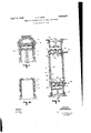
- Fig. l is a view, in sectional. elevation, of a finished air-cooled type of cyhnder structure 1929. ⁇ Serial No. 354,112.
- Various kinds of alloy steels may be employed in the method herein proposed. Steels containing aluminum, chromium, manganese, silicon or molybdenum, either separately or in any desired combination, may be considered to be nitridable.
- I employ a steel known in the trade as Nitralloy and embodying the following constituents:
- inder structure composed of a cylinder or barrel portion 10 .provided with a series of annularly-extending cooling fins 11. Secured to the upper end of the cylinder or barrel portion 10 in any approved manner, as by shrinking and screw ⁇ threads 12, 1s a cylinder head 13 generally composed of aluminum or some aluminum alloy. Disposed within the cylinder 10 is a piston 14 Per cent reciprocable therein in a manner well under- C 0 20 1,30 stood in the art. Mn 0.40 0 60 Referring now tothe process of manufac- P 0 0Q5 M3,X.
- S1 0025 M,X that first of all a steel is selected for the cyli 0 50 Max inder barrel 10 which has such properties Ni 0 20 Max that -it may be readily hardened by mtridmg. Cir 0 75 h 1.50
- Such a steel may, 1f desired, be .so I heat-treated as to vhave physical properties ened.
- Such a steel may be hardened for use in cylinder structures by placing it in a retort, raising the temperature of the retort sufficiently, for example, between 900 and 1050" F., and disposing some substance capable of giving off nitrogen such as, for example, am-
- the cylinder 10 i-s rough machined from a piece of steel of the foregoing character. Thereafter, I may, if I4 so desire, heat treat it to relieve it of any internal strains or stresses. It is then machined to finish size and is preferably tted with a cap 15', Fig. 2, in order to prevent the threads 12 from being nitrided.
- suitable cylinders may be produced byl subjecting them to the foregoing hardening process for a period of from 24 to 90 hours, the length oftime being dependent upon the size, design andservice requirements of the cylinder.
- the cylinder Upon completion of the hardening process the cylinder is removed from the retort after which the cap 15 is removed from the cylinder and the head 13 fitted thereto in a manner well understood in the art.
- a cylinder maybe produced having both its inner surface or bore'as well as its exterior surface hardened to a very high degrec so that friction in the cylinder bore is lessened, excessive wear of the cylinder bore is avoided and any tendency for the exterior surfaces to corrodeV is eliminated. "Such a form of cylinder may be said to have a maximum length of useful life.
- I have assumed that all ofthe hardened surface portions have' been provided with anequal depth of hardness. However, in some instances, I may desire to provide one portion of the cylinder structure with a depth of ⁇ hardness greater than another portion and this may be readily accomplished in accordance with my improved process. For example, assuming that it is "desired to provide a greater depth of hardness for the bore of the cylinder structure than the exterior surface of the cylinder structure, I may cover the exterior surface, leaving the bore of the cylinder exposed, and submit the cylinder structure to the nitriding process. After the nitriding process has continued for the proper length of time, thecylinder structure may be removed from the retort and the cover removed from ⁇ the exterior surface of the cylinder structure.
- the cylinderstructure may-be again disposed in the retort whereupon hardening of the exterior surface is effected and additional hardening of the bore is also effected.
- FIG. 3 shows a cyll inder of the water cooled type having an inner cylindrical sleeve 21 and an outer jacket sleeve 22 defining therewith an intervening cooling jacket 23.
- Cooling fluid for example, water may be supplied to the cooling jacket 23 through an inlet 24 and discharged throughan outlet 25.
- the sleeve 21 and the jacket sleeve 22 of a cylinder structure of the type shown in Fig. 3 are preferably first .formed from separate pieces of material after which the jacket sleeve 22 is secured upon the cylinder sleeve 21 by a shrinkingprocess.
- the end-portions of the jacket sleeve may be welded to the cylinder sleeve as at 32 and 33.
- the jacket sleeve may be welded to the cylinder sleeve in the vicinity of the cylinder ports, as at 34, 35
- the entire cylinder structure may be disposed in a retort and heated in the presence of ammoniapgas in order that all of the surfaces of the c linder may absorb the nitrogen given off by the ammonia gas and become hardened.
- the flanges 37 A may be utilized to protect the threads 38 from the nitriding process.
- the cylinder structure may be removed from the retort and' there is thus produced a cylinder of the water' cooled type having a hardened bore, having a hardened exterior surface resistive to corrosion or the influence ofdampness in the atmosphere, and an interior jacket space, all surfaces of which are very hard.
- the invention in its broader aspects, ing by any suitable medium. That is, the invention, considered from a broad point of view, consists in providing a suitablecylinder structure having portions to be hardened, and, in some cases, portions not to be hardened, in covering the portions not to be contemplates hardenhardened by some suitable material, and then in subjectingthe cylinder structure to the influences of a suitable hardening agent and under proper conditions.
- What I claim is The method of manufacturing an engine cylinder structure of relatively light Weight having an inner bored surface portion and an exterior exposed surface portion which comprises forming the cylinder structure. of a nitridable steel of smallthickness, covering the exterior surface portion of said cylinder structure While leaving the inner bored surface portion exposed, heating the c linder structure in an atmosphere of a su stance giving ofi' nitrogen in order to harden the inner bored surface portion, removing the cover from the exterior surface portion of the cylinder structure, and thereafter again heating the cylinder structure in an atmosphere of a 40 substance giving oli' nitrogen in order to harden the exterior surface portion and to still further harden the inner bored surface portion, thereby providing cylinder structure having the required thickness of unnitrided material to provide the required strength and having mlnimum requisite thickness of nitrided material to provide maximum lightness.
Landscapes
- Chemical & Material Sciences (AREA)
- Chemical Kinetics & Catalysis (AREA)
- Engineering & Computer Science (AREA)
- Materials Engineering (AREA)
- Mechanical Engineering (AREA)
- Metallurgy (AREA)
- Organic Chemistry (AREA)
- Solid-Phase Diffusion Into Metallic Material Surfaces (AREA)
- Heat Treatment Of Articles (AREA)
Description
April 12., 1932.
H; T. HERR METHOD OF MANUFACTURING CYLINDER STRUCTURES Fiied April 1o, 1929 lll/11114110111110111171 www WITNESS l ATTORNEY Patented Apr. 12, 1932 UNITED STATI-:s
PATENT oFFicE HERBERT T. HERR, 0F PHILADELPHIA., PENNSYLVANIA, ASSIGNOR T0 WESTINGHOUSE ELECTRIC & MANUFACTURING COMPANY, A CORPQRATION 0F PENNSYLVANIA METHOD 0F MANUFACTURING CYLINDER STRUCTURES Application led April 10,
My invention relates to a method or process of manufacturing cylinder structures and particularly cylinder structures adapted. for use in internal combustion engines and it has for an object to provide a novel and improved method or process of the foregoing character which shall be susceptible of easy and practical accomplishment and at the same time capable of producing a cylinder structure having improvedphysical properties.
It has for afurther object to provide an improved process or method of manufacture capable of producing a cylinder structure which shall be less subject to wear than cylinders heretofore manufactured and which shall be non-corrodible.
It has for still another object to provide amethod or process of the foregoing character which shall be capable of producing a cylinder structure having an inner or bored surface of such a character that the amount of sliding friction created by a working piston reciprocating therein shall be materially less thanthe amount, created in cylinders constructed in accordance with the methods or processes of the prior art.
It has for still another object to provide a process or. method ofl manufacture of the foregoing character which shall be capable of producing a cylinder of the water-jacket type wherein the interior surfaces of the jacket contacting with the cooling water shall Abe of such a character' as to effectively resist corrosion thereof.
It has for'still another object to provide a method or process ofthe foregoing character wherein the cylinder structure shall be composed of asteel which may have its surfaces hardenedby the Aabsorption of nitrogen and wherein the cylinder structure may be hardened by a nitriding p rocc.
These and other objects are effected by my invention, as will be apparent from the following description and claim taken in con- -nection with the accompanying drawings,
forming a part of this application, in which: Fig. lis a view, in sectional. elevation, of a finished air-cooled type of cyhnder structure 1929. `Serial No. 354,112.
proved method or process of manufacture.
It is well known that the cylinders of in- A ternal combustion engines wear continuously in their bores because of the friction which takes place as a result of the rubbing action created between the bore of the cylinder and the piston and its piston rings. As the wear increases, the bore of the cylinder becomes more and more deformed, resulting in objectionable leakage of lubricating oil past the piston and piston rings and ultimately re- `quiring that the cylinder be either rebored or discarded. In addition, the exterior surfaces of the cylinder and particularly, if it is of the air-cooled type, are subject to intensive corrosive action because of dampness` prevailing in the atmosphere or because of its use in the' propulsion of aircraft of the marine type.
I have, therefore, conceived of a process or method of manufacture, whereby cylinders of the foregoing character may be readily manufactured having both their interior and exterior surfaces hardened to a very high degree. As a result, because of the very hard character of the cylinder bore, the friction created between the piston and the cylinder wall is materially lessened and consequently excessive wear or Vdeformation of the cylinder bore is avoided. In addition, the exterior surface of the cylinder, being also very hard, is preserved and is not subject to corrosion as in the ordinary cylinder.
In accordance with my invention, I form the cylinder of a steel which may be hardi ened by nitriding, that is,-.by the absorptie-n cylinder structure is entirely avoided. Various kinds of alloy steels may be employed in the method herein proposed. Steels containing aluminum, chromium, manganese, silicon or molybdenum, either separately or in any desired combination, may be considered to be nitridable. Preferably, I employ a steel known in the trade as Nitralloy and embodying the following constituents:
inder structure composed of a cylinder or barrel portion 10 .provided with a series of annularly-extending cooling fins 11. Secured to the upper end of the cylinder or barrel portion 10 in any approved manner, as by shrinking and screw `threads 12, 1s a cylinder head 13 generally composed of aluminum or some aluminum alloy. Disposed within the cylinder 10 is a piston 14 Per cent reciprocable therein in a manner well under- C 0 20 1,30 stood in the art. Mn 0.40 0 60 Referring now tothe process of manufac- P 0 0Q5 M3,X. turing the foregoing cylinder,'1t is noted S1 0025 M,X that first of all a steel is selected for the cyli 0 50 Max inder barrel 10 which has such properties Ni 0 20 Max that -it may be readily hardened by mtridmg. Cir 0 75 h 1.50 Preferably, the steel mentioned heretofore Mo 0 15 0 25" and known in the trade as lltralloy 1s em- Al 0 50 125 ployed. Such a steel may, 1f desired, be .so I heat-treated as to vhave physical properties ened.
Such a steel may be hardened for use in cylinder structures by placing it in a retort, raising the temperature of the retort sufficiently, for example, between 900 and 1050" F., and disposing some substance capable of giving off nitrogen such as, for example, am-
' monia gas, into the retort for a suiiicient length of time to obtain the depth of surface hardness required. In this way, a cylinder structure is easily and readily produced which, obviously, has improved wearing qualities.
In addition to cylinders of the air cooled type, my method or process of manufacture is equally applicable to cylinders of the water cooled or water-jacketed type wherein, not only may the bore of the cylinder and its exterior surfaces be made relativel hard, but the entire interior surfaces of the ]acket space may also be hardened so that the cooling water passing through the jacket cannot corrode the same. This constitutesa very important feature of my invention because of the fact that, lalthough the interior surfaces of the water-jacket space or spaces may be relatively inaccessible, nevertheless, by my improved method or process of manufacture, the entire surfaces of such spaces may be readily hard- One of the i advantages of my improved method or process of manufacture res` les Iin the fact that the temperatures involved in the process of nitriding are relatively low, that is, substantially lower than the temperatures ordinarily involved in such heat treatingA operations as, for example, case' hardening. In addition, no quenching-or drawing operation is involved so that the entire cylinder structure, when completed, may have its surfaces hardened without any danger of dis torting or vwarping the same.
Referring now to the drawings for examples of cylinders which may be constructed in accordance' with my improved process or method, I show in Fig. 1, a cylequivalent to those of chrome nickel steel and hence a very light cylinder, consistent with the strength thereof, may be produced. In
accordance with `my improved method, the cylinder 10 i-s rough machined from a piece of steel of the foregoing character. Thereafter, I may, if I4 so desire, heat treat it to relieve it of any internal strains or stresses. It is then machined to finish size and is preferably tted with a cap 15', Fig. 2, in order to prevent the threads 12 from being nitrided.
It is thenv disposed in a closed retort, thetemperature of which is raised, for example, to between 900 and 1050o F., and ammonia gas is allowed to iiow into the retort. vThis 'mi constitutes the process of nitriding and it `continues until such time as the'steel has absorbed sufficient of the nitrogen given oi by the ammonia to provide the depth of hard- -ness required. In other words, the longer the cylinder is retained in the atmosphere of ammonia, the greater the depth of hardness. I have found that with a steel of the foregoing character, suitable cylinders may be produced byl subjecting them to the foregoing hardening process for a period of from 24 to 90 hours, the length oftime being dependent upon the size, design andservice requirements of the cylinder.
Upon completion of the hardening process the cylinder is removed from the retort after which the cap 15 is removed from the cylinder and the head 13 fitted thereto in a manner well understood in the art.
From the foregoing description, it will be apparent that, by my process of manufacturing, a cylinder maybe produced having both its inner surface or bore'as well as its exterior surface hardened to a very high degrec so that friction in the cylinder bore is lessened, excessive wear of the cylinder bore is avoided and any tendency for the exterior surfaces to corrodeV is eliminated. "Such a form of cylinder may be said to have a maximum length of useful life.
In the foregoing embodiment, I have assumed that all ofthe hardened surface portions have' been provided with anequal depth of hardness. However, in some instances, I may desire to provide one portion of the cylinder structure with a depth of` hardness greater than another portion and this may be readily accomplished in accordance with my improved process. For example, assuming that it is "desired to provide a greater depth of hardness for the bore of the cylinder structure than the exterior surface of the cylinder structure, I may cover the exterior surface, leaving the bore of the cylinder exposed, and submit the cylinder structure to the nitriding process. After the nitriding process has continued for the proper length of time, thecylinder structure may be removed from the retort and the cover removed from `the exterior surface of the cylinder structure. Thereafter the cylinderstructure may-be again disposed in the retort whereupon hardening of the exterior surface is effected and additional hardening of the bore is also effected. After final removal of the cylinder structure from the retort, it
will be obvious that the depth of hardness of the bore of the cylinder structure will be greater than that of its exterior surface. It will, therefore be apparent that, in accordance with my improved process of manufacture, it is possible to produce cylinder structures wherein difi'erent depths of hardness structures, as required.
Referring now to Fig. 3, this shows a cyll inder of the water cooled type having an inner cylindrical sleeve 21 and an outer jacket sleeve 22 defining therewith an intervening cooling jacket 23. Cooling fluid, for example, water may be supplied to the cooling jacket 23 through an inlet 24 and discharged throughan outlet 25. Y
Although my invention is applicable to any type of water cooled cylinder, I have shown, for purposes of illustration, a cylinder of the opposed piston type provided with longitudinally spaced scavenging fluid inlet ports 26 and exhaust outlet ports 27. L0- cated intermediate of the ends of the cylinder are circular, fuel inlet ports 28 and disposed within the cylinder are lopposed pistons 29 and 31 arranged to reciprocate therein in a manner' well' understood in the art.
As disclosed and claimed in a copending application of mine, Serial No. 331,809, Patent No. 1,820,069 issued on Aug. 25, 1931 e'ntitled Method of manufacturing an engine cylinder and assigned tothe Westinghouse Electric & Manufacturing Company, the sleeve 21 and the jacket sleeve 22 of a cylinder structure of the type shown in Fig. 3 are preferably first .formed from separate pieces of material after which the jacket sleeve 22 is secured upon the cylinder sleeve 21 by a shrinkingprocess. In order to insure thorough water-tightness of the cooling jacket, the end-portions of the jacket sleeve may be welded to the cylinder sleeve as at 32 and 33. In addition, the jacket sleeve may be welded to the cylinder sleeve in the vicinity of the cylinder ports, as at 34, 35
and 36.
Referring now to my improved. process or method of manufacturing a cylinder of the `foregoing character, it is noted that first of that of the jacket sleeve and the cylinder sleeve, in that it is susceptible of hardening by nitriding. j
After assembly of the jacket sleeve upon the cylinder sleeve, the entire cylinder structure may be disposed in a retort and heated in the presence of ammoniapgas in order that all of the surfaces of the c linder may absorb the nitrogen given off by the ammonia gas and become hardened. The flanges 37 A may be utilized to protect the threads 38 from the nitriding process.
the cylinder structure may be removed from the retort and' there is thus produced a cylinder of the water' cooled type having a hardened bore, having a hardened exterior surface resistive to corrosion or the influence ofdampness in the atmosphere, and an interior jacket space, all surfaces of which are very hard.
Upon completion of the nitriding process,
Attention is especially invited to the fact l that my method permits of hardening the entire, relatively inaccessible, surfaces of the jacket space 2.3, the ammonia gas having` ready access thereto through the cooling water connections ordinarily provided in the cylinder structure. V
While I prefer to use the nitriding process for hardening those portions of the cylinder structure required Vto be hardened because of the peculiar adaptability of the nitriding process on account of the lo`w tem'- peratures involved and the absence of changing the physical properties ofthe element hardened, nevertheless it will be understood by those skilled in the art that my invention, in its broader aspects, ing by any suitable medium. That is, the invention, considered from a broad point of view, consists in providing a suitablecylinder structure having portions to be hardened, and, in some cases, portions not to be hardened, in covering the portions not to be contemplates hardenhardened by some suitable material, and then in subjectingthe cylinder structure to the influences of a suitable hardening agent and under proper conditions.
5 From the foregoing, it will be apparent that I have evolved a novel method or process of manufacturing cylinder structures of both air and Water cooled types whereby the surfaces of the cylinders are readily hardened 1G to a very high degree so as to resist wear and corrosion and that the method proposed is susceptible of ready accomplishment and capable of producing cylinder structures having improved physical qualities.
v WhileI have shown my invention in several forms, it will be obvious to those skilled inthe art that it is not so limited, but is susceptible of various other changes and modications, Without departing from the spirit thereof, and I desire, therefore, that only such limitationsshall be placed thereupon as are imposed by the prior art or as are speciicially set forth in the appended claim.
What I claim is The method of manufacturing an engine cylinder structure of relatively light Weight having an inner bored surface portion and an exterior exposed surface portion which comprises forming the cylinder structure. of a nitridable steel of smallthickness, covering the exterior surface portion of said cylinder structure While leaving the inner bored surface portion exposed, heating the c linder structure in an atmosphere of a su stance giving ofi' nitrogen in order to harden the inner bored surface portion, removing the cover from the exterior surface portion of the cylinder structure, and thereafter again heating the cylinder structure in an atmosphere of a 40 substance giving oli' nitrogen in order to harden the exterior surface portion and to still further harden the inner bored surface portion, thereby providinga cylinder structure having the required thickness of unnitrided material to provide the required strength and having mlnimum requisite thickness of nitrided material to provide maximum lightness.
In testimony whereof, I have hereunto subscribed my name this 1st day of April, 1929.
HERBERT T. HERR.
Priority Applications (1)
| Application Number | Priority Date | Filing Date | Title |
|---|---|---|---|
| US354112A US1853562A (en) | 1929-04-10 | 1929-04-10 | Method of manufacturing cylinder structures |
Applications Claiming Priority (1)
| Application Number | Priority Date | Filing Date | Title |
|---|---|---|---|
| US354112A US1853562A (en) | 1929-04-10 | 1929-04-10 | Method of manufacturing cylinder structures |
Publications (1)
| Publication Number | Publication Date |
|---|---|
| US1853562A true US1853562A (en) | 1932-04-12 |
Family
ID=23391918
Family Applications (1)
| Application Number | Title | Priority Date | Filing Date |
|---|---|---|---|
| US354112A Expired - Lifetime US1853562A (en) | 1929-04-10 | 1929-04-10 | Method of manufacturing cylinder structures |
Country Status (1)
| Country | Link |
|---|---|
| US (1) | US1853562A (en) |
Cited By (13)
| Publication number | Priority date | Publication date | Assignee | Title |
|---|---|---|---|---|
| US2575394A (en) * | 1944-12-27 | 1951-11-20 | Union Carbide & Carbon Corp | Reciprocating piston and cylinder mechanism |
| US2639244A (en) * | 1950-07-15 | 1953-05-19 | Remington Arms Co Inc | Metal finishing method |
| US2938260A (en) * | 1954-04-02 | 1960-05-31 | Curtiss Wright Corp | Method of fabricating cylinder barrels |
| US4447275A (en) * | 1981-01-28 | 1984-05-08 | Nippon Piston Ring Co., Ltd. | Cylinder liner |
| US6799541B1 (en) | 2002-10-25 | 2004-10-05 | Darton International, Inc. | Cylinder sleeve with coolant groove |
| US20080314353A1 (en) * | 2007-06-22 | 2008-12-25 | Eric Highum | Cylinder liner and method construction thereof |
| US20110271932A1 (en) * | 2010-04-27 | 2011-11-10 | Achates Power, Inc. | Combustion chamber constructions for opposed-piston engines |
| US20120073541A1 (en) * | 2010-08-16 | 2012-03-29 | Achates Power, Inc. | Fuel injection spray patterns for opposed-piston engines |
| US9211797B2 (en) | 2013-11-07 | 2015-12-15 | Achates Power, Inc. | Combustion chamber construction with dual mixing regions for opposed-piston engines |
| US9309807B2 (en) | 2011-05-18 | 2016-04-12 | Achates Power, Inc. | Combustion chamber constructions for opposed-piston engines |
| US9512779B2 (en) | 2010-04-27 | 2016-12-06 | Achates Power, Inc. | Swirl-conserving combustion chamber construction for opposed-piston engines |
| US10180115B2 (en) | 2010-04-27 | 2019-01-15 | Achates Power, Inc. | Piston crown bowls defining combustion chamber constructions in opposed-piston engines |
| US20250052300A1 (en) * | 2023-08-08 | 2025-02-13 | Nabtesco Corporation | Power transmission pin for speed changer, speed changer and method of manufacturing power transmission pin for speed changer |
-
1929
- 1929-04-10 US US354112A patent/US1853562A/en not_active Expired - Lifetime
Cited By (18)
| Publication number | Priority date | Publication date | Assignee | Title |
|---|---|---|---|---|
| US2575394A (en) * | 1944-12-27 | 1951-11-20 | Union Carbide & Carbon Corp | Reciprocating piston and cylinder mechanism |
| US2639244A (en) * | 1950-07-15 | 1953-05-19 | Remington Arms Co Inc | Metal finishing method |
| US2938260A (en) * | 1954-04-02 | 1960-05-31 | Curtiss Wright Corp | Method of fabricating cylinder barrels |
| US4447275A (en) * | 1981-01-28 | 1984-05-08 | Nippon Piston Ring Co., Ltd. | Cylinder liner |
| US6799541B1 (en) | 2002-10-25 | 2004-10-05 | Darton International, Inc. | Cylinder sleeve with coolant groove |
| US20080314353A1 (en) * | 2007-06-22 | 2008-12-25 | Eric Highum | Cylinder liner and method construction thereof |
| US7617805B2 (en) | 2007-06-22 | 2009-11-17 | Federal-Mogul World Wide, Inc. | Cylinder liner and method construction thereof |
| US9512779B2 (en) | 2010-04-27 | 2016-12-06 | Achates Power, Inc. | Swirl-conserving combustion chamber construction for opposed-piston engines |
| US20110271932A1 (en) * | 2010-04-27 | 2011-11-10 | Achates Power, Inc. | Combustion chamber constructions for opposed-piston engines |
| US8800528B2 (en) * | 2010-04-27 | 2014-08-12 | Achates Power, Inc. | Combustion chamber constructions for opposed-piston engines |
| US10180115B2 (en) | 2010-04-27 | 2019-01-15 | Achates Power, Inc. | Piston crown bowls defining combustion chamber constructions in opposed-piston engines |
| US9593627B2 (en) | 2010-04-27 | 2017-03-14 | Achates Power, Inc. | Combustion chamber constructions for opposed-piston engines |
| US20120073541A1 (en) * | 2010-08-16 | 2012-03-29 | Achates Power, Inc. | Fuel injection spray patterns for opposed-piston engines |
| US8820294B2 (en) * | 2010-08-16 | 2014-09-02 | Achates Power, Inc. | Fuel injection spray patterns for opposed-piston engines |
| US9309807B2 (en) | 2011-05-18 | 2016-04-12 | Achates Power, Inc. | Combustion chamber constructions for opposed-piston engines |
| US9211797B2 (en) | 2013-11-07 | 2015-12-15 | Achates Power, Inc. | Combustion chamber construction with dual mixing regions for opposed-piston engines |
| US20250052300A1 (en) * | 2023-08-08 | 2025-02-13 | Nabtesco Corporation | Power transmission pin for speed changer, speed changer and method of manufacturing power transmission pin for speed changer |
| US12422021B2 (en) * | 2023-08-08 | 2025-09-23 | Nabtesco Corporation | Power transmission pin for speed changer, speed changer and method of manufacturing power transmission pin for speed changer |
Similar Documents
| Publication | Publication Date | Title |
|---|---|---|
| US1853562A (en) | Method of manufacturing cylinder structures | |
| US2647847A (en) | Method for interfitting machined parts | |
| CA1059395A (en) | Ported engine cylinder liner with selectively hardened bore | |
| US5148780A (en) | Cylinder liner and method for manufacturing the same | |
| US2279671A (en) | Cylinder liner | |
| CN102272491B (en) | Piston rings and cylinder liners | |
| US2125106A (en) | Method of producing cylinders for internal combustion engines | |
| CN102282283B (en) | Nitridable piston rings | |
| US2541116A (en) | Hardened metallic structure | |
| US3305918A (en) | Method of producing composite castforged aluminum piston with bonded ferrous ring carrier | |
| US20060249105A1 (en) | Anti-cavitation diesel cylinder liner | |
| US2064155A (en) | Valve and seat for internal combustion engines | |
| US2362622A (en) | Injection engine | |
| US2827373A (en) | Ni-cr-co-mo valve seat insert | |
| US2201405A (en) | Piston | |
| US1455028A (en) | Air-cooled engine cylinder and method of making same | |
| US1914083A (en) | Nitrided spring | |
| US1688300A (en) | Vania | |
| US2181947A (en) | Method of making thin walled plated pistons for internal combustion engines | |
| US4484547A (en) | Valve guide and method for making same | |
| JP3846811B2 (en) | Piston for internal combustion engine | |
| US2768918A (en) | Cast iron valve seat insert | |
| US3472651A (en) | Engine components of cast iron having ni,cr,and ti as alloying elements | |
| JPH10204678A (en) | Sliding member and its production | |
| US2194872A (en) | Manufacture of cylinders and cooling jackets of internal combustion engines |