EP2998043B1 - Méthode de fabrication d'un composant travaillé - Google Patents
Méthode de fabrication d'un composant travaillé Download PDFInfo
- Publication number
- EP2998043B1 EP2998043B1 EP14797040.4A EP14797040A EP2998043B1 EP 2998043 B1 EP2998043 B1 EP 2998043B1 EP 14797040 A EP14797040 A EP 14797040A EP 2998043 B1 EP2998043 B1 EP 2998043B1
- Authority
- EP
- European Patent Office
- Prior art keywords
- blank
- section
- outer edge
- line
- top plate
- Prior art date
- Legal status (The legal status is an assumption and is not a legal conclusion. Google has not performed a legal analysis and makes no representation as to the accuracy of the status listed.)
- Active
Links
- 238000004519 manufacturing process Methods 0.000 title claims description 40
- 238000003825 pressing Methods 0.000 claims description 66
- 238000005452 bending Methods 0.000 claims description 55
- 238000000034 method Methods 0.000 claims description 42
- 230000001629 suppression Effects 0.000 claims description 26
- 238000007781 pre-processing Methods 0.000 claims description 4
- 238000005336 cracking Methods 0.000 description 72
- 238000010586 diagram Methods 0.000 description 36
- 229910000831 Steel Inorganic materials 0.000 description 18
- 239000010959 steel Substances 0.000 description 18
- 230000000052 comparative effect Effects 0.000 description 16
- 230000009467 reduction Effects 0.000 description 13
- 230000002787 reinforcement Effects 0.000 description 11
- 239000000463 material Substances 0.000 description 6
- 230000012447 hatching Effects 0.000 description 4
- 238000005304 joining Methods 0.000 description 4
- 229910052751 metal Inorganic materials 0.000 description 4
- 239000002184 metal Substances 0.000 description 4
- 239000007769 metal material Substances 0.000 description 4
- 238000003466 welding Methods 0.000 description 4
- 238000006073 displacement reaction Methods 0.000 description 3
- 230000000694 effects Effects 0.000 description 3
- 230000008569 process Effects 0.000 description 3
- 229910052782 aluminium Inorganic materials 0.000 description 2
- XAGFODPZIPBFFR-UHFFFAOYSA-N aluminium Chemical compound [Al] XAGFODPZIPBFFR-UHFFFAOYSA-N 0.000 description 2
- 238000005520 cutting process Methods 0.000 description 2
- 238000013461 design Methods 0.000 description 2
- 238000005516 engineering process Methods 0.000 description 2
- 238000011835 investigation Methods 0.000 description 2
- 230000007246 mechanism Effects 0.000 description 2
- 238000009966 trimming Methods 0.000 description 2
- 238000005299 abrasion Methods 0.000 description 1
- 239000000956 alloy Substances 0.000 description 1
- 229910045601 alloy Inorganic materials 0.000 description 1
- 230000008859 change Effects 0.000 description 1
- 238000010276 construction Methods 0.000 description 1
- 238000007796 conventional method Methods 0.000 description 1
- 230000007423 decrease Effects 0.000 description 1
- 230000007547 defect Effects 0.000 description 1
- 230000001419 dependent effect Effects 0.000 description 1
- 230000003090 exacerbative effect Effects 0.000 description 1
- 230000001747 exhibiting effect Effects 0.000 description 1
- 238000003698 laser cutting Methods 0.000 description 1
- 238000012986 modification Methods 0.000 description 1
- 230000004048 modification Effects 0.000 description 1
- 230000002093 peripheral effect Effects 0.000 description 1
- 238000012545 processing Methods 0.000 description 1
- 238000009877 rendering Methods 0.000 description 1
- 238000012360 testing method Methods 0.000 description 1
Images


Classifications
-
- B—PERFORMING OPERATIONS; TRANSPORTING
- B21—MECHANICAL METAL-WORKING WITHOUT ESSENTIALLY REMOVING MATERIAL; PUNCHING METAL
- B21D—WORKING OR PROCESSING OF SHEET METAL OR METAL TUBES, RODS OR PROFILES WITHOUT ESSENTIALLY REMOVING MATERIAL; PUNCHING METAL
- B21D22/00—Shaping without cutting, by stamping, spinning, or deep-drawing
- B21D22/02—Stamping using rigid devices or tools
-
- B—PERFORMING OPERATIONS; TRANSPORTING
- B21—MECHANICAL METAL-WORKING WITHOUT ESSENTIALLY REMOVING MATERIAL; PUNCHING METAL
- B21D—WORKING OR PROCESSING OF SHEET METAL OR METAL TUBES, RODS OR PROFILES WITHOUT ESSENTIALLY REMOVING MATERIAL; PUNCHING METAL
- B21D22/00—Shaping without cutting, by stamping, spinning, or deep-drawing
- B21D22/20—Deep-drawing
- B21D22/22—Deep-drawing with devices for holding the edge of the blanks
-
- B—PERFORMING OPERATIONS; TRANSPORTING
- B21—MECHANICAL METAL-WORKING WITHOUT ESSENTIALLY REMOVING MATERIAL; PUNCHING METAL
- B21D—WORKING OR PROCESSING OF SHEET METAL OR METAL TUBES, RODS OR PROFILES WITHOUT ESSENTIALLY REMOVING MATERIAL; PUNCHING METAL
- B21D53/00—Making other particular articles
- B21D53/88—Making other particular articles other parts for vehicles, e.g. cowlings, mudguards
-
- B—PERFORMING OPERATIONS; TRANSPORTING
- B21—MECHANICAL METAL-WORKING WITHOUT ESSENTIALLY REMOVING MATERIAL; PUNCHING METAL
- B21D—WORKING OR PROCESSING OF SHEET METAL OR METAL TUBES, RODS OR PROFILES WITHOUT ESSENTIALLY REMOVING MATERIAL; PUNCHING METAL
- B21D22/00—Shaping without cutting, by stamping, spinning, or deep-drawing
- B21D22/20—Deep-drawing
- B21D22/26—Deep-drawing for making peculiarly, e.g. irregularly, shaped articles
Definitions
- the present invention relates to a method of manufacturing a worked component.
- Automotive body shells include unit construction structures (monocoque structures) in which framework members such as front pillars, center pillars, side sills, roof rails, side members and the like, are joined together with various formed panels such as hood ridges, dash panels, front floor panels, rear floor front panels, and rear floor rear panels.
- Framework members that generally have a closed cross-section, such as front pillars, center pillars, and side sills, are assembled by joining configuration members such as front pillar reinforcement, center pillar reinforcement, and side sill outer reinforcement, to other configuration members such as outer panels and inner panels.
- a framework member 1 is formed by joining configuration members 2 to 5 together by spot welding.
- the configuration member 2 has a substantially hat shaped lateral cross-section profile including a top plate section 2a, a pair of vertical wall sections 2b, 2b extending downward from either end of the top plate section 2a, and flange sections 2c, 2c extending outward from lower ends of the vertical wall sections 2b, 2b.
- the top plate section 2a of the structural member 2 has an L-shaped external profile in plan view (such a configuration member is also referred to below as an "L-shaped profile component").
- the strength and rigidity of the framework member 1 are secured by including such a configuration member 2.
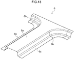
- Fig. 13 is an explanatory diagram illustrating a configuration member (also sometimes referred to below as a "T-shaped profile component") 6 including a top plate section 6a that has a T-shaped external profile in plan view.
- the T-shaped profile component 6 also has a substantially hat shaped lateral cross-section profile including the top plate section 6a, a pair of left and right vertical wall sections 6b, 6b, and flange sections 6c, 6c.
- Y-shaped profile components not illustrated in the drawings, in which the T-shaped profile component 6 has been modified so as to give the top plate section a Y-shaped external profile in plan view.
- Pressing by drawing is normally employed when manufacturing the L-shaped profile component 2, the T-shaped profile component 6, or the Y-shaped profile component by pressing, in order to suppress creasing from occurring.
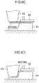
- Fig. 14A is a schematic explanatory diagram illustrating pressing by drawing at a stage prior to the start of forming
- Fig. 14B is a schematic explanatory diagram illustrating forming completion.
- a die 7, a punch 8, and a crease suppresser 9 are employed to press material of a metal plate (a blank) 10 into a press formed article, for example an L-shaped profile component 11, by drawing.
- Fig. 15 is a schematic explanatory diagram illustrating an example of the press formed article 11 manufactured by pressing using drawing
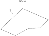
- Fig. 16 is a schematic explanatory diagram illustrating the blank 10 that is the forming material of the press formed article 11.
- Fig. 17 is a schematic explanatory diagram in which a crease suppression region 10a of the blank 10 is illustrated by hatching
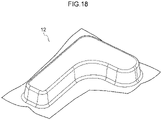
- Fig. 18 is a schematic explanatory diagram illustrating an intermediate press formed article 12 prior to trimming.
- the L-shaped profile component 11 illustrated in Fig. 15 is manufactured by a pressing method using drawing
- (1) the plate metal material 10 illustrated in Fig. 16 is placed between the die 7 and the punch 8 illustrated in Fig. 14A
- the crease suppression region 10a surrounding the plate metal material 10 as illustrated in Fig. 17 is held firmly in place by the crease suppresser 9 and the die 7, (3) as illustrated in Fig. 14B
- the die 7 and the punch 8 are moved relative to each other in the pressing direction (the vertical direction) and the plate metal material 10 is pressed into the intermediate press formed article 12 illustrated in Fig. 18 by drawing, and (4) unwanted portions surrounding the intermediate press formed article 12 are trimmed, so as to obtain the L-shaped profile component 11.
- Fig. 19 is a schematic explanatory diagram illustrating examples of conditions under which the pressing defects of creasing and cracking occur in the intermediate press formed article 12.
- creasing is liable to occur at regions ⁇ where there is excessive inflow of the blank 10 into the mold during the drawing process, and cracking is liable to occur at regions ⁇ where there is localized reduction in plate thickness during the drawing process.
- creasing and cracking are liable to occur due to insufficient ductility of the blank 10.
- JP-A Japanese Patent Application Laid-Open
- Patent Documents 1 to 4" describe pressing methods using bending to manufacture components with a simple cross-section profile such as a hat shaped or a Z-shaped profile extending along the entire length in the length direction.
- these methods are not applicable to manufacture of products with complex profiles such as the L-shaped profile component 2, the T-shaped profile component 6, or a Y-shaped profile component.
- Patent Document 5 In pamphlet of International Publication No. 2011/145679 (also referred to below as "Patent Document 5"), the present inventors have previously disclosed a patented invention (specification of Japanese Patent No. 5168429 ) relating to a method that enables the L-shaped profile component 2, the T-shaped profile component 6, or a Y-shaped profile component to be pressed by bending with good yield, and without creasing or cracking occurring, even when a high tensile steel plate with low ductility is employed for the blank.
- a patented invention specificallyation of Japanese Patent No. 5168429 relating to a method that enables the L-shaped profile component 2, the T-shaped profile component 6, or a Y-shaped profile component to be pressed by bending with good yield, and without creasing or cracking occurring, even when a high tensile steel plate with low ductility is employed for the blank.
- This patented invention is a method to form, from a blank, a component having a substantially hat shaped lateral cross-section profile and a vertical wall section including a bent portion forming a protrusion toward a top plate section side in plan view, such as an L-shaped profile member.
- a blank is placed between a die, and a pad and a bending mold, and (1) in a state in which the pad applies pressure to a portion of a location of the blank corresponding to the top plate section and serving as an out-of-plane deformation suppression region, and also in a state in which an end portion of a portion of the blank corresponding to the L-shape lower side is present in the same plane as the top plate section, moving the die and the bending mold relative to each other in a vertical direction so as to form an L-shaped profile component by forming a vertical wall section and a flange section while sliding (moving in-plane) the end portion of the portion of the blank corresponding to the L-shape lower side over a location of the die corresponding to the top plate section.
- the pad is placed in the vicinity or in contact with a portion of the location of the blank corresponding to the top plate section and serving as an out-of-plane deformation suppression region, and in a state in which a gap between the pad and the die is maintained at from the plate thickness of the blank to 1.1 times the plate thickness of the blank, and also in a state in which the end portion of the blank at the portion corresponding to the L-shape lower side is present in the same plane as the top plate section, moving the die and the bending mold relative to each other in a vertical direction so as to form the L-shaped profile component by forming a vertical wall section and a flange section while sliding (moving in-plane) the end portion of the blank at the portion corresponding to the L-shape lower side over the location of the die corresponding to the top plate section of the blank.
- the method of pressing by bending is referred to as a "free bending method".
- yield is improved since there is no need to provide a large trim region to suppress creasing, such as is always provided at a location of the blank corresponding to a portion at the L-shape lower side of the L-shaped profile component when pressing by normal drawing.
- JP S 64 66024 A discloses a blank to be subjected to drawing to form a container-like part, the blank comprising a bulging part protruding upwardly.
- a method of manufacturing a worked component comprising: a top plate section comprising, of a pair of outer edge portions, at least one outer edge portion that has, in plan view, a straight-line outer edge portion of a straight line and a curved-line outer edge portion that is contiguous to the straight-line outer edge portion and that curves in a concave shape so as to move away from the other outer edge portion toward an outer side; a vertical wall section comprising a straight vertical wall portion that is bent downward from the outer edge portion and that is formed following the straight-line outer edge portion, and a curved vertical wall portion that is formed following the curved-line outer edge portion; and a flange section comprising a straight-line flange portion that extends from the straight vertical wall portion toward the outer side and that is formed following the straight-line outer edge portion, and a curved-line flange portion that is formed following the curved-line outer edge portion and that extends from the curved vertical wall portion toward the outer side
- a free bending method is a technological pressing method that enables cold pressing of L-shaped profile components, T-shaped profile components, or the like from high strength blanks, at low cost and without cracking and creasing occurring.
- edge cracking occurs at an L-shape base section of the top plate section 11a (the portion B in Fig. 15 ) (also sometimes referred to below as “top plate edge cracking").
- Paragraph 0058 of Patent Document 5 refers to providing an excess portion of from 25 mm to 100 mm in cases in which the width of the flange section is less than 25 mm. However, there is no specific detail regarding the shape of the excess portion. There is also no description of providing an excess portion in cases in which the width of the flange section is from 25 mm to 100 mm.
- An object of the present invention is to provide a manufacturing method that prevents or suppresses creasing and cracking during pressing, and a press formed article in which creasing and cracking have been prevented from occurring.
- the present invention is based on the technological concept of "suppressing excessive inflow of the blank from a top plate section to a vertical wall section so as to enable top plate edge cracking to be prevented from occurring, while preventing flange cracking from occurring in the press formed article by devising a way to provide an excess portion to an edge portion of a portion that will form a flange section in a blank with an opened-out shape of a press formed article of an L-shaped profile component, a T-shaped profile component, or moreover a Y-shaped profile component".
- the present invention is based on the technological concept of "providing an excess portion to an edge portion of a portion that will form a flange section in a blank with an opened-out shape of a press formed article of a T-shaped profile component, an L-shaped profile component, or moreover a Y-shaped profile component, and also providing a first recess, a protrusion, and a second recess to an edge portion of the excess portion, thereby enabling the occurrence of flange cracking to be suppressed by the protrusion provided to the excess portion, and enabling top plate edge cracking to be suppressed from occurring due to being able to reduce the amount of displacement from the top plate section to the vertical wall section by straightening out of both the first recess and the second recess provided to the excess portion".
- a first aspect of the present invention provides a method of manufacturing a worked component as defined in claim 1.
- a second aspect of the present invention provides a method of manufacturing a worked component as defined in claim 4.
- Pressing forming the blank or the forming plate of the present invention enables the occurrence of creasing and cracking in the press formed article to be prevented or suppressed.
- the press formed article manufacturing method of the present invention enables a press formed article to be manufactured in which the occurrence of creasing and cracking has been suppressed or prevented.
- the press formed article of the present invention is one that has been manufactured in a desired shape from a high strength blank, with the occurrence of creasing and cracking suppressed or prevented.
- plan view means viewed along the direction of relative movement between a die and a bending mold during pressing.
- the press formed article is an L-shaped profile component.
- the present invention is not limited to an L-shaped profile component, and may be similarly applied to press formed articles such as a T-shaped profile component and a Y-shaped profile component that include both a lateral cross-section profile described later and a curved portion.
- the blank is a metal plate suitable for pressing, and the material properties thereof are not particularly limited.
- the blank is preferably plate metal suitable for pressing, such as a steel plate, an aluminum plate, or an alloy plate with main components of steel or aluminum.
- the blank is a steel plate.
- Fig. 1 is a simplified explanatory diagram of the shape of an L-shaped profile component 20, this being an elongated press formed article according to the present exemplary embodiment.
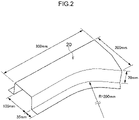
- Fig. 2 is an explanatory diagram illustrating an example of dimensions of relevant portions of the press formed article.
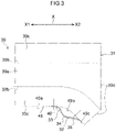
- Fig. 3 is a schematic explanatory diagram illustrating the shape of a blank 30 of the L-shaped profile component 20 according to the present exemplary embodiment.
- the L-shaped profile component 20 is an elongated press formed article that is elongated along a length direction (the arrow X direction in Fig. 1 (also referred to below as the X direction)).
- the dimension of the L-shaped profile component 20 in the X direction is in a range of from 100 mm to 1400 mm, and is, for example, 300 mm, as illustrated in Fig. 2 .
- the L-shaped profile component 20 has a substantially hat shaped lateral cross-section profile, and includes a top plate section 20a with a substantially L-shape in plan view, two vertical wall sections 20c, 20c extending downward from both ends in a direction orthogonal to the X direction of the top plate section 20a (the arrow Y direction orthogonal to the X direction in the present exemplary embodiment (also referred to below as the Y direction)) of the top plate section 20a, and two flange sections 20d, 20d extending toward the outside from lower end portions of the two vertical wall sections 20c, 20c.
- Ridge line sections 20b, 20b having rounded profile lateral cross-sections are provided between the top plate section 20a and the vertical wall sections 20c, 20c.
- the top plate section 20a includes outer edge portions 24a, 24b that form boundary lines with the ridge line sections 20b, 20b at both Y direction end portions of the top plate section 20a.
- the outer edge portion 24a includes a straight-line outer edge portion 24a1 extending along a straight line in plan view from one X direction (also referred to below as the "X1 direction") end portion, a curved-line outer edge portion 24a2 that is contiguous to the straight-line outer edge portion 24a1 and curves so as to form a convex shape protruding toward the inside in plan view, and that diverges from the outer edge portion 24b on progression toward the other X direction (also referred to below as the "X2 direction”), and a straight-line outer edge portion 24a3 that is contiguous to the curved-line outer edge portion 24a2 and extends along a straight line in plan view.
- the outer edge portion 24b on the opposite side is formed by a straight-line outer edge portion having a purely straight line shape in
- the top plate section 20a extends along the X direction and has a specific width w in the Y direction.
- a width w1 at an X1 direction end portion of the top plate section 20a is in a range of from 50 mm to 200 mm, and is, for example, 100 mm, as illustrated in Fig. 2 .
- a width w3 at an X2 direction end portion of the top plate section 20a is in a range of from 70 mm to 1000 mm, and is, for example, 200 mm as illustrated in Fig. 2 .
- a "base section of the L” means the X2 direction end portion 25 of the top plate section 20a, as illustrated in Fig. 1 .
- the end portion is formed from plural portions in plan view (two straight lines in the present exemplary embodiment), all of these portions are included.
- the vertical wall section 20c on the outer edge portion 24a side includes a straight vertical wall portion 20c1 following the straight-line outer edge portion 24a1 and forming a straight line shape from the X1 direction end portion in plan view, a curved vertical wall portion 20c2 following the curved-line outer edge portion 24a2 and forming a curved shape that is convex so as to protrude toward the inside in plan view, and a straight vertical wall portion 20c3 following the straight-line outer edge portion 24a3 and forming a straight line shape in plan view.
- the vertical wall section 20c on the opposite side is formed from a vertical wall section with a purely straight line shape in plan view.
- the height of the vertical wall sections 20c, 20c is in a range of from 20 mm to 120 mm, and is, for example, 70 mm as illustrated in Fig. 2 . If the height of the vertical wall section 20c is below 0.2 times the length of the curved-line outer edge portion 24a2, or below 20 mm, creasing of the vertical wall section 20c is liable to occur.
- the height of the vertical wall section 20c is accordingly preferably 0.2 times the length of the curved-line outer edge portion 24a2 or greater, and also 20 mm or greater.
- the maximum radius of curvature of the vertical wall section 20c (curved vertical wall portion 20c2) in plan view namely the maximum radius of curvature (R MAX ) of the outer edge portion 24a (curved-line outer edge portion 24a2), is preferably from 5 mm to 300 mm. If the maximum radius of curvature is less than 5 mm, a maximum curvature portion juts out locally and is therefore vulnerable to cracking.
- the maximum radius of curvature of the curved vertical wall portion 20c2 (curved-line outer edge portion 24a2) is thus preferably 100 mm or below.
- the flange section 20d on the outer edge portion 24a side includes a straight-line flange portion 20dl following the outer edge portion 24a and with an edge from the X1 direction end portion forming a straight line shape in plan view, a curved-line flange portion 20d2 in a curved shape having an edge indented toward the inside, and a straight-line flange portion 20d3 forming a straight line shape.
- the flange section 20d on the opposite side is formed from a straight-line flange portion with a purely straight line shape in plan view.
- the two flange sections 20d, 20d both have a width in a range of from 10 mm to 100 mm, for example 35 mm, as illustrated in Fig. 2 .
- the width h i of the flange section 20d at a side further toward a first end portion A than the center C of the curved vertical wall portion 20c2 may be from 25 mm to 100 mm. More specifically, pressing is preferably performed such that the width h i of the flange section 20d is from 25 mm to 100 mm in the section D in Fig.
- the width h i of the flange section 20d is defined as the distance of the flange section 20d in a direction orthogonal to a tangent at a freely selected position of an edge of the flange section 20d.
- the occurrence of creasing and cracking in the flange section 20d can be suppressed by setting the flange width h i of the flange section 20d in the section D from 25 mm to 100 mm.
- an intermediate pressed body having a flange section 20d of width 25 mm or greater is preferably manufactured by pressing, with the unwanted portion then being trimmed off.
- the L-shaped profile component 20 is divided into a first portion 21 and a second portion 22 at an X direction boundary position between the straight-line outer edge portion 24a1 and the curved-line outer edge portion 24a2.
- the vertical wall sections 20c, 20c are formed with parallel straight line shapes in plan view, such that the width w1 of the top plate section 20a is substantially uniform.
- the curved vertical wall portion 20c2 (curved-line outer edge portion 24a2) curves substantially toward the plate thickness direction, such that the width w of the top plate section 20a gradually increases on progression toward the X2 direction end portion, thereby giving the top plate section 20a a substantially L-shape in plan view.
- the radius of curvature of the curved vertical wall portion 20c2 is in a range of from 5 mm to 500 mm, and is, for example, 200 mm as illustrated in Fig. 2 .
- curved-line outer edge portion 24a2, the curved vertical wall portion 20c2, and the curved-line flange section 20d2 are also collectively referred to as a curved portion 23.
- the curved-line outer edge portion 24a2 of the L-shaped profile component 20 may have a profile with a uniform curvature, an elliptical profile, a profile including plural curvatures, or a profile including a straight-line portion.
- the top plate section 20a in plan view the top plate section 20a is present to the outside of the curved arc shape of the ridge line section 20b (curved-line outer edge portion 24a2), and the flange section 20d is present at the inside (the arc center side) of the curved arc shape of the ridge line section 20b.
- the top plate section 20a does not need to be a perfectly flat face, and various additional shapes (such as recesses or protrusions) may be imparted to the top plate section 20a according to the design of the press formed article.
- the X1 direction end portion is referred to as the end portion A (first end portion), and the X2 direction end portion is referred to as the end portion B (second end portion).
- width w3 of the X2 direction end portion of the top plate section 20a is 150 mm or greater.
- center pillar reinforcement this being a typical example of a T-shaped profile component
- the L-shaped profile component 20 is formed using the free bending method employing the blank 30, described later, rendering modification of the shape of the blank in order to prevent the occurrence of flange cracking and top plate edge cracking unnecessary, and enabling a width w3 of 150 mm or greater to be secured for the X2 direction end portion of the top plate section 20a.
- a portion of the second portion 22 including the X2 direction end portion configures a joint portion with other members (for example a roof rail or a side sill), and joining to the other members through this portion is performed by appropriate means (such as spot welding or laser welding).
- the press formed article 20 accordingly enables an increase in the joint surface area of the portion configuring the joint portion with other members, and enables the joint strength with the other members to be raised. Increased bending rigidity and increased twisting rigidity of the automotive body shell is enabled when the press formed article is an automotive vehicle body configuration member (such as various pillar outer reinforcements or sill outer reinforcements).
- the L-shaped profile component 20 that is a press formed article according to the present exemplary embodiment is configured as described above.
- the blank 30 is manufactured by cutting a specific shape out of a steel plate material using an appropriate method (such as laser cutting).
- Pre-processing performed on the blank 30 includes, for example, bending to form light protrusions in the interior of the blank 30, pressing by drawing, and hole cutting. Such pre-processing may be performed on the blank 30 as appropriate in consideration of the dimensions and shape of the press formed article 20.
- the blank 30 is configured with a shape 31 of the press formed article 20 as it is opened-out (the shape illustrated by single-dotted intermittent lines in Fig. 3 , also sometimes referred to as the "opened-out shape” in the present specification), namely a shape combining a portion 30a that will form the top plate section 20a, portions 30b, 30b that will form the outer edge portions 24a, 24b, and portions 30c, 30c that will form the ridge line sections 20b, 20b, the vertical wall sections 20c, 20c, and the flange sections 20d, 20d, to which a bulging portion 48 is additionally provided at an edge of a portion that will form the flange section 20d including the curved-line flange portion 20d2.
- An edge of the bulging portion 48 is configured by an excess portion 32 provided with a first recess 33, a protrusion 34, and a second recess 35 that satisfy Condition 1, described below.
- an edge portion 45 of the portion of the opened-out shape 31 that will form the flange section 20d is formed, from the X1 direction end portion, with a straight-line edge portion 45a, a curved-line edge portion 45b, and a straight-line edge portion 45c, similarly to the flange section 20d of the L-shaped profile component 20.
- Condition 1 Taking a curvature in a direction toward the inside of the blank 30 as having a negative sign, and taking a curvature in the opposite direction to toward the inside of the blank 30 as having a positive sign, the first recess 33 with a negative sign curvature, the protrusion 34 with a positive sign curvature, and the second recess 35 with a negative sign curvature are formed in this sequence along the edge of the excess portion 32.
- the blank 30 preferably also satisfies Conditions 2 and 3 below.
- the edge length of the protrusion 30 (edge lengths in plan view are sometimes also referred to below as “edge lengths”) is the edge length of the curved-line edge portion 45b or shorter.
- the protrusion 34 is provided in order to prevent flange cracking, and, since it is the curved-line flange portion 20d2 where flange cracking is liable to occur, the edge length of the protrusion 34 is preferably the edge length of the curved-line edge portion 45b or shorter.
- plan view means as viewed along a direction orthogonal to the extension direction of the plate.
- the edge lengths of the first recess 33, the protrusion 34, and the second recess 35 refer to the distance between inflection points on the edge of the blank 30.
- the absolute values of the respective curvatures of the first recess 33 and the second recess 35 are both 0.1 (1/mm) or below.
- the first recess 33 and the second recess 35 are provided in order to prevent top plate edge cracking, and the first recess 33 and the second recess 35 straighten out and suppress inflow of the blank 30 into the mold during pressing. Accordingly, if the absolute values of the respective curvatures of the first recess 33 and the second recess 35 are large, stress concentration occurs at the first recess 33 and the second recess 35 respectively, and edge cracking is liable to occur at the first recess 33 and the second recess 35 respectively. Accordingly, the absolute values of the respective curvatures of the first recess 33 and the second recess 35 are preferably set to 0.1 (1/mm) or below.
- the opened-out shape 31 is the shape on which the shape of the blank 30 is based, and is the shape of the top plate section 20a, the ridge line sections 20b, 20b, the vertical wall sections 20c, 20c, and the flange sections 20d, 20d as opened out flat.
- the opened-out shape 31 is the shape obtained by adding, to the portion that will form the top plate section 20a, portions that will form the ridge line sections 20b, 20b, portions that will form the vertical wall sections 20c, 20c, and portions that will form the flange sections 20d, 20d.
- the excess portion 32 is a portion that is the basis for preventing flange cracking and top plate edge cracking, and the range and size for forming the excess portion 32 may be decided from these perspectives.
- an excess portion 32 having a width (the distance from a boundary line between the vertical wall section 20c and the flange section 20d, to the edge of the excess portion 32) of from 1/2 to 3/2 times the height of the vertical wall section 20c of the L-shaped profile component 20 product is preferably formed at the portion that will form the curved-line flange portion 20d2 of the L-shaped profile component 20. This is to prevent fluctuations in the excess portion 32 according to the shape (length) of the flange section 20d of the L-shaped profile component 20.
- Flange cracking occurs if the width of the excess portion 32 is less than 1/2 the height of the vertical wall section 20c, and flange creasing and vertical wall cracking occur if the width of the excess portion 32 exceeds 3/2 of the height of the vertical wall section 20c.
- a reduction in the plate thickness of the flange section 20d during forming is suppressed, thereby enabling good pressing to be achieved not only when employing the blank 30 configured from a steel plate with high ductility and comparatively low strength (for example, a steel plate with tensile strength of approximately 400 MPa), but also when employing blanks configured from a steel plate with low ductility and comparatively high strength (for example, a steel plate with tensile strength of approximately 1600 MPa).
- This thereby enables high strength plate steel with a tensile strength from 400 MPa to 1600 MPa to be employed for the blank 30.
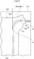
- An X2 direction end portion 30d of the blank 30 preferably has a shape in which at least a portion of the end portion is disposed in the same plane as the portion 30a that will form the top plate section 20a, namely preferably has a shape in which the end portion remains unaffected during pressing. Moreover, as illustrated in Fig. 7 described later, out of the blank 30, the end portion at a location corresponding to an out-of-plane deformation suppression region (region F) is preferably in the same plane as the portion 30a.
- a portion of the blank 30 that is an end portion of the blank 30 and that is present further to the side that will form the top plate section 20a than a portion that will form the curved-line outer edge portion 24a2 and the straight-line outer edge portion 24a3 in a location corresponding to the out-of-plane deformation suppression region, is preferably present in the same plane as the portion that will form the top plate section 20a.
- a straight-line portion may be present at one or both locations out of between the first recess 33 and the protrusion 34, and between the second recess 35 and the protrusion 34 (see the straight-line portions 46, 47 in Fig. 20E ). Accordingly, in cases in which small respective radii suffice for the curvature of the first recess 33, the protrusion 34, and the second recess 35, the excess portion 32 may be formed so as to include desired edges of the first recess 33, the protrusion 34, and the second recess 35, without the need to employ large radii of curvature, with this being preferable.
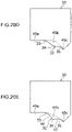
- blanks 30 include a blank 30 in which the first recess 33, the protrusion 34, and the second recess 35 of the excess portion 32 are all provided within the range of the curved-line edge portion 45b (see Fig. 20A ), a blank 30 in which the start point of the first recess 33 is at a straight-line edge portion 45a (see Fig. 20B ), and a blank 30 in which the start point of the second recess 35 is at a straight-line edge portion 45c (see Fig. 20C ).
- first recess 33 is formed to the straight-line edge portion 45a
- the protrusion 34 is formed to the curved-line edge portion 45b
- the second recess 35 is formed to the straight-line edge portion 45c (see Fig. 20D ).
- a blank 30 is conceivable in which the straight-line portions 46, 47 that are straight line shaped in plan view are formed between the first recess 33 and protrusion 34, and between the protrusion 34 and the second recess 35 (see Fig. 20E ).
- the straight-line portions 46, 47 that are straight line shaped in plan view are formed between the first recess 33 and protrusion 34, and between the protrusion 34 and the second recess 35 (see Fig. 20E ).
- the press formed article manufacturing method is one in which the press formed article 20 according to the present invention, as described above, is manufactured by pressing the blank 30 according to the present invention as described above using cold bending that employs the free bending method described in Patent Document 5. Since the free bending method is already known through Patent Document 5, simplified explanation is given below.
- the free bending method explained here employs an L-shaped profile component 20Y and a blank 30Y that are shaped differently to the L-shaped profile component 20 and the blank 30 employed in the above explanation; however, there is no change to the operation and the like. Moreover, configuration elements of the L-shaped profile component 20Y and the blank 30Y that are configuration elements similar to those of the L-shaped profile component 20 and the blank 30 are allocated the same reference numerals, and detailed explanation thereof is omitted.
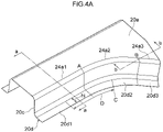
- Fig. 4B is a perspective view of the curved portion 23 of the L-shaped profile component 20 obtained by the present manufacturing method.
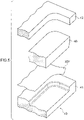
- Fig. 5 is a schematic explanatory drawing of the mold unit 40 employed to carry out the present manufacturing method.
- Fig. 6A and Fig. 6B are cross-sections taken along line a-a in Fig. 4B , and schematically illustrate respective states prior to starting pressing, and on completion of pressing, using the mold unit 40 illustrated in Fig. 5 .
- Fig. 6C and Fig. 6D are cross-sections taken along line b-b in Fig. 4B , and schematically illustrate respective states prior to starting pressing, and on completion of pressing, using the mold unit 40 illustrated in Fig. 5 .
- the mold unit 40 includes a die 41 on which the blank 30Y is placed, a pad 42 that is disposed on the other side of the blank 30 to that of the die 41, and a bending mold 43 that presses the blank 30 by moving relative to the die 41.
- a drive mechanism of the pad 42 may employ springs or hydraulics in cases in which the blank 30 is applied with pressure to an extent that permits in-plane movement of locations corresponding to the out-of-plane deformation suppression region (region F), described later, and the like.
- the pad 42 may also be configured by a gas cushion.
- the drive mechanism of the pad 42 may be an electric cylinder or a hydraulic servo when employed in cases in which the vertical wall section 20c and the flange section 20d are formed in a state in which a gap between the pad 42 and the die 41 at a portion in the vicinity of, or contacting, the out-of-plane deformation suppression region (region F) is maintained at a gap from the plate thickness of the blank 30 to 1.1 times the plate thickness of the blank 30.
- region F out-of-plane deformation suppression region
- the vertical wall section 20c and the flange section 20d are formed in a state in which it is possible for a region of at least a portion of the blank 30Y (at least a portion of a region of the blank 30 corresponding to the top plate section 20a) to slide (move in-plane) over a location of the die 41 corresponding to the top plate section 20a.
- the vertical wall section 20c and the flange section 20d are formed by placing the blank 30Y between the die 41, and the pad 42 and bending mold 43, and at least a portion of the blank 30Y is slid over the location of the die 41 corresponding to the top plate section 20a in a state in which the pad 42 is in the vicinity of, or in contact with, the blank 30Y.
- a state in which the pad 42 is in the vicinity of the blank 30Y means a state in which the blank 30Y and the pad 42 do not contact each other when the blank 30Y slides over the location of the die 41 corresponding to the top plate section 20a, but the blank 30Y and the pad 42 do contact each other if the blank 30Y attempts to deform (or buckle) out-of-plane above this location. More strictly speaking, "a state in which the pad 42 is in the vicinity of the blank 30Y” means a state in which the gap between the pad 42 and the die 41 is maintained at greater than 1.0 times the plate thickness of the blank 30Y, up to and including 1.1 times the plate thickness of the blank 30Y.
- forming may be performed in a state in which the gap between the pad 42 and the die 41 at a portion where the pad 42 is in the vicinity of, or in contact with, the out-of-plane deformation suppression region (region F) that is a portion of the blank 30Y, is maintained at greater than 1.0 times the plate thickness of the blank 30Y, and up to and including 1.1 times the plate thickness of the blank 30Y.
- the gap between the pad 42 and the die 41 is more preferably set at from the plate thickness to 1.03 times the plate thickness since slight creasing occurs when the gap between the pad 42 and the die 41 is 1.03 times the plate thickness of the blank 30Y or greater.
- the vertical wall sections 20c, 20c and the flange sections 20d, 20d are formed at the position of the cross-section on line a-a by placing the portion that will form the top plate section 20a (see the portion 30a that will form the top plate section 20a in Fig. 3 ) on the die 41, and placing the pad 42 so as to hold down or be in the vicinity of this portion while pressing both sides of the blank 30 with the bending mold 43.
- this is performed, as illustrated in Fig. 6C and Fig.
- the vertical wall section 20c and the flange section 20d are formed at the position of the cross-section on line b-b by placing a portion corresponding to the out-of-plane deformation suppression region F on the die 41, and pressing only one side of the blank 30 with the bending mold 43.
- a gap is provided between the pad 42 and the die 41.
- the pad 42 may also apply pressure to the blank 30Y.
- the pad 42 may apply pressure to a portion of the blank 30Y serving as the out-of-plane deformation suppression region (region F) with a specific load pressure.
- pressure refers to the average surface pressure when the pressing force applied by the pad is divided by the surface area of the contact portion between the pad 42 and the blank 30Y, and a certain amount of localized variation may be present.
- Fig. 7 is an explanatory diagram in which the out-of-plane deformation suppression region (region F) of the blank 30Y is illustrated by hatching.
- the pad employed When applying pad pressure, preferably has a shape covering the entire portion of the blank 30 that contacts the top plate face of the die 41, or with a shape that covers part of the portion of the blank 30 that contacts the top plate face of the die 41 and includes the entire out-of-plane deformation suppression region (region F).
- a pad may be employed with a shape that avoids the additional shape portions, that at least includes a region of the out-of-plane deformation suppression region (region F) that extends up to at least 5 mm from the position that will form the outer edge portion 24a (the curved-line outer edge portion 24a2, the straight-line outer edge portion 24a3), and that covers 50% or greater of the surface area of the out-of-plane deformation suppression region (region F).
- a pad with a segmented pressure application face may also be employed.
- the region that will form the top plate section 20a and that extends up to at least 5 mm from the position that will form the outer edge portion 24a is preferably applied with pressure by the pad 42.
- the curved vertical wall portion 20c2 and the curved-line flange portion 20d2 are preferably formed by placing a region that is on the inside of the portion 30a of the blank 30 that will form the top plate section 20a and that extends up to at least 5 mm from the position that will form the outer edge portion 24a, in the vicinity of, or in contact with, the pad 42.
- creasing is liable to occur in the top plate section 20a if the pad 42 only applies pressure to a region that extends up to at least 4 mm from the outer edge portion 24a.
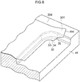
- Fig. 8 is a perspective view illustrating a state in which the blank 30Y has been placed on the die 41.
- Fig. 9 is a perspective view illustrating a state after the blank 30Y has been formed into the L-shaped profile member 20Y.
- the blank 30Y is placed on the die 41, and, in a state in which the portion 30a that will form the top plate section 20a of the L-shaped profile member 20Y is applied with pressure toward the die 41 by the pad 42.
- the bending mold 43 is then lowered in the pressing direction, and the vertical wall sections 20c. 20c and the flange sections 20d, 20d are formed as illustrated in Fig. 9 .
- the blank 30 is deformed so as to follow the shape of the vertical wall section 20c and the flange section 20d by lowering the bending mold 43 in the pressing direction.
- a location of the blank 30 corresponding to the end portion 30d flows into the vertical wall section 20c.
- the press formed article manufacturing method according to the present exemplary embodiment is a method for manufacturing from the blank 30 by cold pressing using the above free bending method.
- the blank 30 when performing pressing by bending, includes the first recess 33, the protrusion 34, and the second recess 35 at the edge portion of the excess portion 32, thereby increasing the amount of the blank that flows into the mold from the protrusion 34 provided to the excess portion 32, and enabling the occurrence of flange cracking to be suppressed.
- Both the first recess 33 and the second recess 35 that are respectively provided on either side of the protrusion 34 in the excess portion 32 straighten out during pressing, thereby enabling a reduction in the amount of displacement from the portion 30a that will form the top plate section 20a toward the vertical wall section 30c, and enabling cracking at the top plate edge to be suppressed from occurring.
- the blank 30 employed in pressing using such bending includes the first recess 33, the protrusion 34, and the second recess 35 at the edge portion of the excess portion 32, making it possible not only to suppress flange cracking from occurring using the protrusion 34 provided to the excess portion 32, but also enabling a reduction in the amount of displacement from the portion 30a that will form the top plate section 20a toward the vertical wall section 30c due to the first recess 33 and the second recess 35 provided to the excess portion both straightening out, thereby enabling the occurrence of top plate edge cracking to be suppressed, even in cases in which the L-shaped profile component 20 is set with a long width w3.
- press formed articles 20 with the shape and dimensions illustrated in Fig. 1 and Fig. 2 were manufactured using the various shaped blanks 36 to 39, and 30 (Comparative Examples 1 to 4, Example) (tensile strength 1180 MPa, plate thickness 1.6 mm), by holding down the portion of the blank that will form the top plate section 20a with a pad, and then employing the free bending method to bend with a bending forming.
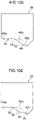
- Fig. 10A illustrates the blank 36 (Comparative Example 1), this having an opened-out shape based on the L-shaped profile component 20.
- Fig. 10B to Fig. 10E each illustrates blanks in which an excess portion 32 is formed to the edge of the portion that will form the flange section 20d.
- Fig. 10B illustrates the blank 37 (Comparative Example 2), formed with a recess portion 46 with a curvature on the edge of the excess portion 32 having a negative sign (radius of curvature 300 mm).
- Fig. 10C illustrates the blank 38 (Comparative Example 3), in which the excess portion 32 is formed with a straight-line edge 47.
- Fig. 10A illustrates the blank 36 (Comparative Example 1), this having an opened-out shape based on the L-shaped profile component 20.
- Fig. 10B to Fig. 10E each illustrates blanks in which an excess portion 32 is formed to the edge of the portion that will form the flange section 20d.
- FIG. 10D illustrates the blank 39 (Comparative Example 4) formed with a recess 48 and a protrusion 49, each having a radius of curvature of 150 mm, next to each other along the edge of the excess portion 32.
- Fig. 10E illustrates the blank 30 (the present Example) formed with the first recess 33, the protrusion 34, and the second recess 35, each having a radius of curvature of 100 mm, next to each other along the edge of the excess portion 32.
- Table 1 illustrates the results of investigating the plate thickness reduction ratio and cracking in the portion A and in the portion B respectively in the press formed article 20 illustrated in Fig. 1 .
- the location A1 to the location A3 in Table 1 refer to the locations in Fig. 1 .
- Table 1 Blank Shape Comparative Example 1 (36) Comparative Example 2 (37) Comparative Example 3 (38) Comparative Example 4 (39)
- flange cracking occurred at the portion A in the Comparative Example 1. It can be seen that although the plate thickness reduction ratio at the portion A decreases as the surface area provided for the excess portion 32 becomes larger, as in the Comparative Examples 2 to 4, and the risk of flange cracking at the portion A is lower, the plate thickness reduction ratio becomes larger at the portion B, and so the risk of top plate edge cracking at the portion B is higher.
- the plate thickness reduction ratio at the portion A not only can the smallest plate thickness reduction ratio at the portion A be achieved, but also the plate thickness reduction ratio at the portion B can also be kept smaller than in the blanks 38, 39 of the Comparative Examples 3 and 4. This thereby enables the occurrence of top plate edge cracking to be prevented at the portion B as well as preventing flange section edge cracking at portion A.
- the blank 30 is formed into an intermediate pressed body by the free bending method in this manner. After performing further bending as required to the intermediate pressed body formed in this manner, trimming is performed to give the external profile the desired shape, and holes are formed to manufacture the pressed body product.
- Fig. 11 is a perspective view illustrating the shape of a press formed article 50, this being a configuration component of a vehicle framework component produced as a sample using the present Example.
- the press formed article 50 has an overall length of 1000 mm, and a top plate section 50a has a width of 100 mm at both the X1 direction and the X2 direction end portions, a height of a vertical wall section 50c of 70 mm. and a width of a flange section 50d of 25 mm.
- Blanks for the press formed article 50 are formed from three types of high tensile steel plates. having respective tensile strengths of 590 MPa grade, 980 MPa grade, and 1180 MPa grade, and each having a plate thickness of 1.6 mm.
- the excess portion 32 illustrated in Fig. 3 is formed to the edge of a portion that will form a curving portion of a flange, and the first recess 33, the protrusion 34, and the second recess 35 are provided to the edge of the excess portion 32.
- the press formed article 50 illustrated in Fig. 11 is manufactured by employing the three types of blank with different strength levels, using the free bending method in which each blank is placed on a punch, and the portion that will form the top plate section is held down by a pad, before then bending using a die.
- the present invention enables high quality and efficient forming with high strength steel plates and the like.
- the present invention has a high degree of applicability in steel plate processing technology industries, for example in the automotive industry.
Claims (13)
- Procédé de fabrication d'un composant ouvré comprenant :une section de plaque haute (20a) comprenant, parmi une paire de portions de bord externe (24a, 24b), au moins une portion de bord externe (24a) qui comporte, en vue en plan, une portion de bord externe en ligne droite (24a1) d'une ligne droite et une portion de bord externe en ligne courbe (24a2) qui est contiguë à la portion de bord externe en ligne droite et qui se courbe en une forme concave de manière à s'éloigner de l'autre portion de bord externe (24b) vers un côté externe ;une section de paroi verticale (20c) comprenant une portion de paroi verticale droite (20c1) qui est cintrée vers le bas à partir de la portion de bord externe et qui est formée en suivant la portion de bord externe en ligne droite, et une portion de paroi verticale courbe (20c2) qui est formée en suivant la portion de bord externe en ligne courbe ; etune section de bride (20d) comprenant une portion de bride en ligne droite (20d1) qui s'étend depuis la portion de paroi verticale en ligne droite vers le côté externe et qui est formée en suivant la portion de bord externe en ligne droite, et une portion de bride en ligne courbe (20d2) qui est formée en suivant la portion de bord externe en ligne courbe et qui s'étend depuis la portion de paroi verticale en ligne courbe vers le côté externe, le procédé comprenant :la fourniture d'une ébauche en forme de plaque plate (30) comprenant une forme débouchante (31) qui combine des portions (30a, 30b, 30c) qui formeront la section de plaque haute, la section de paroi verticale et la section de bride du composant ouvré, etune portion en excès (32) ménagée à un emplacement correspondant à un bord de la section de bride du composant ouvré, la portion en excès s'évasant de la forme débouchante et étant formée avec une protubérance (34) créant une forme protubérante vers le côté externe, et un premier évidement (33) et un second évidement (35) créant respectivement des formes évidées de chaque côté de la protubérance, au moins la protubérance étant ménagée à un emplacement correspondant à un bord de la portion de bride à ligne courbe du composant ouvré ;le placement de l'ébauche ou d'une plaque de formage comprenant l'ébauche entre une matrice (41), et un tampon (42) et un moule de cintrage (43) ; etdans un état dans lequel une portion (30a) de l'ébauche, ou de la plaque de formage, qui formera une portion d'extrémité de la section de plaque haute, la section de paroi verticale, et la section de bride est présente dans un même plan que la portion (30a) de l'ébauche, ou de la plaque de formage, qui formera la section de plaque haute, le formage à la presse de la section de paroi verticale et la section de bride par cintrage tout en déplaçant la portion de l'ébauche, ou de la plaque de formage, qui formera la portion d'extrémité dans le plan par rapport à un emplacement de la matrice correspondant à la section de plaque haute, en déplaçant relativement soit la matrice soit le moule de cintrage dans une direction de manière à les rapprocher l'un de l'autre, dans un état dans lequel une région de suppression de déformation hors plan (F) qui fait partie de la portion (30a) de l'ébauche, ou de la plaque de formage, qui formera la section de plaque haute, se voit appliquer une pression par le tampon.
- Procédé selon la revendication 1, dans lequel la portion en excès comprend en outre une portion en ligne droite (46, 47) formant une ligne droite en vue en plan entre le premier évidement et la protubérance, et/ou entre la protubérance et le second évidement.
- Procédé selon la revendication 1 ou selon la revendication 2, dans lequel un prétraitement a été effectué sur l'ébauche avant pressage.
- Procédé de fabrication d'un composant ouvré comprenant :une section de plaque haute (20a) comprenant, parmi une paire de portions de bord externe (24a, 24b), au moins une portion de bord externe (24a) qui comporte, en vue en plan, une portion de bord externe en ligne droite (24a1) d'une ligne droite et une portion de bord externe en ligne courbe (24a2) qui est contiguë à la portion de bord externe en ligne droite et qui se courbe selon une forme concave de manière à s'éloigner de l'autre portion de bord externe (24b) vers un côté externe ;une section de paroi verticale (20c) comprenant une portion de paroi verticale droite (20c1) qui est cintrée vers le bas à partir de la portion de bord externe et qui est formée en suivant la portion de bord externe en ligne droite, et une portion de paroi verticale courbe (20c2) qui est formée en suivant la portion de bord externe en ligne courbe ; etune section de bride (20d) comprenant une portion de bride en ligne droite (20d1) qui s'étend depuis la portion de paroi verticale en ligne droite vers le côté externe et qui est formée en suivant la portion de bord externe en ligne droite, et une portion de bride en ligne courbe (20d2) qui est formée en suivant la portion de bord externe en ligne courbe et qui s'étend depuis la portion de paroi verticale en ligne courbe vers le côté externe, le procédé comprenant :la fourniture d'une ébauche en forme de plaque plate (30) comprenant une forme débouchante (31) qui combine des portions (30a, 30b, 30c) qui formeront la section de plaque haute, la section de paroi verticale et la section de bride du composant ouvré, etune portion en excès (32) ménagée à un emplacement correspondant à un bord de la section de bride du composant ouvré, la portion en excès s'évasant de la forme débouchante et étant formée avec une protubérance (34) créant une forme protubérante vers le côté externe, et un premier évidement (33) et un second évidement (35) créant respectivement des formes évidées de chaque côté de la protubérance, au moins la protubérance étant ménagée à un emplacement correspondant à un bord de la portion de bride à ligne courbe du composant ouvré ;le placement de l'ébauche ou d'une plaque de formage comprenant l'ébauche entre une matrice (41), et un tampon (42), et un moule de cintrage (43) ; etdans un état dans lequel une portion de l'ébauche, ou de la plaque de formage, qui formera une portion d'extrémité de la section de plaque haute, la section de paroi verticale, et la section de bride, est présente dans un même plan qu'une portion de l'ébauche, ou de la plaque de formage, qui formera la section de plaque haute, le formage à la presse de la section de paroi verticale et la section de bride par cintrage, en plaçant le tampon au voisinage de, ou en contact avec, une région de suppression de déformation hors plan (F) qui fait partie de la portion de l'ébauche, ou de la plaque de formage, qui formera la section de plaque haute, et en déplaçant relativement soit la matrice, soit le moule de cintrage, dans une direction de manière à les rapprocher l'un de l'autre tout en maintenant un espace entre le tampon et la matrice de l'épaisseur de la plaque à 1,1 fois l'épaisseur de la plaque de l'ébauche, ou de la plaque de formage.
- Procédé selon la revendication 4, dans lequel la portion en excès comprend en outre une portion de ligne droite (46, 47) formant une ligne droite en vue en plan entre le premier évidement et la protubérance, et/ou entre la protubérance et le second évidement.
- Procédé selon la revendication 4 ou la revendication 5, dans lequel un prétraitement a été effectué sur l'ébauche avant pressage.
- Procédé de fabrication d'un article formé à la presse selon l'une quelconque des revendications 1 à 6, dans lequel, en vue en plan de l'ébauche ou de la plaque de formage, la région de suppression de la déformation hors plan est une région qui se trouve sur un côté d'un emplacement qui formera la portion de bord externe à ligne courbe parmi des régions de la portion qui formeront la section de plaque haute qui sont divisées en deux par une ligne d'extension d'une ligne qui formera la portion de bord externe à ligne droite, et qui est une région en contact avec la matrice.
- Procédé de fabrication d'un article formé à la presse selon l'une quelconque des revendications 1 à 7, dans lequel une portion qui est une portion d'extrémité de l'ébauche, ou de la plaque de formage, et qui est présente plus loin vers un côté qui formera la section de plaque haute que la portion de bord externe à ligne courbe hors emplacements correspondant à la région de suppression de déformation hors plan de l'ébauche, ou de la plaque de formage, est présente dans un même plan qu'une portion qui formera la section de plaque haute.
- Procédé de fabrication d'un article formé à la presse selon l'une quelconque des revendications 1 à 8, dans lequel une hauteur de la section de paroi verticale est soit de 0,2 fois la longueur de la portion de bord externe à ligne courbe ou plus, soit de 20 mm ou plus.
- Procédé de fabrication d'un article formé à la presse selon l'une quelconque des revendications 1 à 9, dans lequel la section de paroi verticale et la section de bride sont formées en plaçant le tampon à proximité de, ou en contact avec, une région qui est à l'intérieur d'une portion de l'ébauche, ou de la plaque de formage, qui formera la section de plaque haute, et qui est une région qui s'étend jusqu'à au moins 5 mm de la portion de bord externe à ligne courbe vers le côté qui formera la section de plaque haute.
- Procédé de fabrication d'un article formé à la presse selon l'une quelconque des revendications 1 à 10, dans lequel une largeur de la section de bride, depuis une position centrale de la portion de bord externe à ligne courbe jusqu'à une position séparée de 50 mm ou plus d'une portion d'extrémité de la portion de bord externe à ligne courbe vers le côté de la portion de bord externe à ligne droite, est de 25 mm à 100 mm.
- Procédé de fabrication d'un article formé à la presse selon l'une quelconque des revendications 1 à 11, dans lequel un rayon de courbure maximal de la portion de bord externe à ligne courbe de la section de plaque haute vaut de 5 mm à 300 mm.
- Procédé de fabrication d'un article formé à la presse selon l'une quelconque des revendications 1 à 12, dans lequel une résistance à la traction de l'ébauche, ou de la plaque de formage, vaut de 400 MPa à 1 600 MPa.
Applications Claiming Priority (2)
| Application Number | Priority Date | Filing Date | Title |
|---|---|---|---|
| JP2013101419 | 2013-05-13 | ||
| PCT/JP2014/062750 WO2014185428A1 (fr) | 2013-05-13 | 2014-05-13 | Découpe, plaque moulée, procédé de fabrication de produit moulé sous pression et produit moulé sous pression |
Publications (3)
| Publication Number | Publication Date |
|---|---|
| EP2998043A1 EP2998043A1 (fr) | 2016-03-23 |
| EP2998043A4 EP2998043A4 (fr) | 2017-01-11 |
| EP2998043B1 true EP2998043B1 (fr) | 2022-09-14 |
Family
ID=51898405
Family Applications (1)
| Application Number | Title | Priority Date | Filing Date |
|---|---|---|---|
| EP14797040.4A Active EP2998043B1 (fr) | 2013-05-13 | 2014-05-13 | Méthode de fabrication d'un composant travaillé |
Country Status (11)
| Country | Link |
|---|---|
| US (1) | US10946427B2 (fr) |
| EP (1) | EP2998043B1 (fr) |
| JP (1) | JP6119848B2 (fr) |
| KR (2) | KR101854511B1 (fr) |
| CN (1) | CN105188982B (fr) |
| BR (1) | BR112015028362A2 (fr) |
| CA (1) | CA2912041C (fr) |
| HU (1) | HUE060567T2 (fr) |
| MX (2) | MX2015015496A (fr) |
| TW (1) | TWI555593B (fr) |
| WO (1) | WO2014185428A1 (fr) |
Families Citing this family (20)
| Publication number | Priority date | Publication date | Assignee | Title |
|---|---|---|---|---|
| RU2673259C2 (ru) * | 2014-05-14 | 2018-11-23 | Ниппон Стил Энд Сумитомо Метал Корпорейшн | Заготовка и способ изготовления изделия, получаемого обработкой давлением |
| JP6242363B2 (ja) * | 2015-03-31 | 2017-12-06 | 日新製鋼株式会社 | 成形材製造方法 |
| WO2017002253A1 (fr) * | 2015-07-02 | 2017-01-05 | 日産自動車株式会社 | Procédé de moulage à la presse |
| ES2796369T3 (es) | 2015-07-06 | 2020-11-26 | Nippon Steel Corp | Método y aparato para fabricar componentes de prensado |
| JP6323415B2 (ja) * | 2015-08-31 | 2018-05-16 | Jfeスチール株式会社 | ブランク形状決定方法 |
| JP6350504B2 (ja) * | 2015-12-09 | 2018-07-04 | Jfeスチール株式会社 | ブランク形状決定方法、及びブランク形状修正装置 |
| JP6281670B1 (ja) * | 2016-06-27 | 2018-02-21 | 新日鐵住金株式会社 | プレス部品の製造方法および製造装置 |
| MX2019003975A (es) * | 2016-10-05 | 2019-08-01 | Nippon Steel Corp | Metodo de fabricacion y aparato de fabricacion de articulos formados por prensado. |
| JP6527544B2 (ja) | 2017-03-28 | 2019-06-05 | Jfeスチール株式会社 | プレス成形装置及びプレス成形品の製造方法 |
| MX2020008961A (es) | 2018-02-28 | 2020-10-05 | Jfe Steel Corp | Lamina de metal para moldeado por prensado, dispositivo de moldeado por prensado, y metodo de produccion para componente prensado. |
| JP7131076B2 (ja) * | 2018-05-24 | 2022-09-06 | 日本製鉄株式会社 | プレス品を生産する方法 |
| WO2020144995A1 (fr) * | 2019-01-11 | 2020-07-16 | Jfeスチール株式会社 | Procédé de moulage à la presse, élément d'ébauche de matériau en forme de plaque, article moulé intermédiaire, procédé de fabrication d'article moulé à la presse, et article moulé à la presse |
| US11931788B2 (en) | 2019-01-31 | 2024-03-19 | Jfe Steel Corporation | Method for manufacturing pressed component, and method for manufacturing blank material |
| JP7277725B2 (ja) * | 2019-04-01 | 2023-05-19 | 日本製鉄株式会社 | プレス成形せん断加工方法 |
| JP6942156B2 (ja) * | 2019-05-08 | 2021-09-29 | 本田技研工業株式会社 | センターピラー製造方法 |
| CN114025894B (zh) * | 2019-07-04 | 2023-10-24 | 日本制铁株式会社 | 构造部件的制造方法以及制造装置 |
| US11447228B2 (en) * | 2020-04-23 | 2022-09-20 | The Boeing Company | Methods of manufacture for aircraft substructure |
| CN115214782B (zh) * | 2021-04-16 | 2023-08-15 | 广州汽车集团股份有限公司 | 一种侧围a柱末端结构 |
| WO2023234073A1 (fr) * | 2022-05-31 | 2023-12-07 | Jfeスチール株式会社 | Procédé de moulage à la presse et procédé de fabrication d'un article moulé à la presse |
| CN117338112A (zh) * | 2022-09-21 | 2024-01-05 | 厦门新技术集成有限公司 | 单层塑料板的制造方法、单层塑料板和家具 |
Citations (1)
| Publication number | Priority date | Publication date | Assignee | Title |
|---|---|---|---|---|
| EP2198986A1 (fr) * | 2007-11-21 | 2010-06-23 | Toyota Jidosha Kabushiki Kaisha | Procédé de traitement par presse et appareil de traitement par presse |
Family Cites Families (14)
| Publication number | Priority date | Publication date | Assignee | Title |
|---|---|---|---|---|
| JP2551022B2 (ja) * | 1987-09-04 | 1996-11-06 | トヨタ自動車株式会社 | 絞り加工方法とそのためのプレス型 |
| JPH07290159A (ja) * | 1994-04-28 | 1995-11-07 | Showa Alum Corp | 円弧状入込み部を有する深絞り成形品の製造方法 |
| JPH08103828A (ja) | 1994-10-04 | 1996-04-23 | Nissan Motor Co Ltd | 低温絞り成形方法及び絞り成形用金型装置及びプレス機械 |
| JP3839290B2 (ja) | 2001-09-27 | 2006-11-01 | 株式会社神戸製鋼所 | 金属板の曲げ成形方法 |
| JP4579505B2 (ja) | 2002-09-11 | 2010-11-10 | 株式会社神戸製鋼所 | 金属板のプレス成形用金型および金属板のプレス成形方法 |
| JP4264054B2 (ja) | 2004-06-01 | 2009-05-13 | 株式会社神戸製鋼所 | 曲げ成形方法およびその成形方法に用いる成形金型 |
| KR20070112414A (ko) * | 2005-03-17 | 2007-11-23 | 인더스트리얼 오리가미, 엘엘씨. | 정밀하게 폴딩된 고강도 내피로성 구조체 및 이를 위한시트 |
| JP2008307557A (ja) | 2007-06-13 | 2008-12-25 | Kobe Steel Ltd | 2段プレス成形法 |
| EP2116322B1 (fr) * | 2007-06-26 | 2012-01-25 | Honda Motor Co., Ltd. | Pièce à souder par points |
| JP4386130B2 (ja) * | 2007-11-30 | 2009-12-16 | トヨタ自動車株式会社 | プレス装置用金型および開放絞り成形方法 |
| JP5151784B2 (ja) * | 2008-08-05 | 2013-02-27 | 新日鐵住金株式会社 | センターピラーアウターパネルの製造方法およびセンターピラーアウターパネル用ブランク |
| HUE064402T2 (hu) | 2010-05-19 | 2024-03-28 | Nippon Steel Corp | Sajtolási eljárás L alakú sajtolvány kialakítására |
| EP2644293B1 (fr) | 2010-11-24 | 2016-07-27 | Nippon Steel & Sumitomo Metal Corporation | Procédé pour fabriquer un produit en forme de l |
| JP4747227B2 (ja) | 2011-01-26 | 2011-08-17 | 富士フイルム株式会社 | 放射線画像形成システム |
-
2014
- 2014-05-13 US US14/890,227 patent/US10946427B2/en active Active
- 2014-05-13 TW TW103116927A patent/TWI555593B/zh not_active IP Right Cessation
- 2014-05-13 CN CN201480025431.1A patent/CN105188982B/zh active Active
- 2014-05-13 BR BR112015028362A patent/BR112015028362A2/pt not_active Application Discontinuation
- 2014-05-13 JP JP2015517096A patent/JP6119848B2/ja active Active
- 2014-05-13 KR KR1020157033546A patent/KR101854511B1/ko active IP Right Grant
- 2014-05-13 MX MX2015015496A patent/MX2015015496A/es unknown
- 2014-05-13 EP EP14797040.4A patent/EP2998043B1/fr active Active
- 2014-05-13 KR KR1020187004761A patent/KR20180021228A/ko not_active Application Discontinuation
- 2014-05-13 CA CA2912041A patent/CA2912041C/fr active Active
- 2014-05-13 WO PCT/JP2014/062750 patent/WO2014185428A1/fr active Application Filing
- 2014-05-13 HU HUE14797040A patent/HUE060567T2/hu unknown
-
2015
- 2015-11-09 MX MX2020012461A patent/MX2020012461A/es unknown
Patent Citations (1)
| Publication number | Priority date | Publication date | Assignee | Title |
|---|---|---|---|---|
| EP2198986A1 (fr) * | 2007-11-21 | 2010-06-23 | Toyota Jidosha Kabushiki Kaisha | Procédé de traitement par presse et appareil de traitement par presse |
Also Published As
| Publication number | Publication date |
|---|---|
| KR20180021228A (ko) | 2018-02-28 |
| BR112015028362A2 (pt) | 2017-07-25 |
| KR20160003770A (ko) | 2016-01-11 |
| EP2998043A4 (fr) | 2017-01-11 |
| CN105188982A (zh) | 2015-12-23 |
| CA2912041C (fr) | 2018-03-13 |
| MX2020012461A (es) | 2021-02-09 |
| HUE060567T2 (hu) | 2023-03-28 |
| JPWO2014185428A1 (ja) | 2017-02-23 |
| US10946427B2 (en) | 2021-03-16 |
| TWI555593B (zh) | 2016-11-01 |
| US20160082495A1 (en) | 2016-03-24 |
| CN105188982B (zh) | 2018-01-19 |
| JP6119848B2 (ja) | 2017-04-26 |
| TW201505734A (zh) | 2015-02-16 |
| MX2015015496A (es) | 2016-03-21 |
| EP2998043A1 (fr) | 2016-03-23 |
| WO2014185428A1 (fr) | 2014-11-20 |
| CA2912041A1 (fr) | 2014-11-20 |
| KR101854511B1 (ko) | 2018-05-03 |
Similar Documents
| Publication | Publication Date | Title |
|---|---|---|
| EP2998043B1 (fr) | Méthode de fabrication d'un composant travaillé | |
| CA2788845C (fr) | Procede pour formage a la presse d'elements en forme de l | |
| US10828685B2 (en) | Blank, and pressed article manufacturing method | |
| EP3320996B1 (fr) | Procédé et appareil de fabrication d'un composant de presse | |
| EP3272438B1 (fr) | Procédé permettant de produire un produit moulé à la presse, produit moulé à la presse et dispositif de pressage | |
| EP2524740A1 (fr) | Procédé de formation de presse de composant en L | |
| EP3895824B1 (fr) | Procédé de formage à la presse | |
| EP3597512B1 (fr) | Corps moulé, élément structural et procédé de fabrication de corps moulé |
Legal Events
| Date | Code | Title | Description |
|---|---|---|---|
| PUAI | Public reference made under article 153(3) epc to a published international application that has entered the european phase |
Free format text: ORIGINAL CODE: 0009012 |
|
| 17P | Request for examination filed |
Effective date: 20151214 |
|
| AK | Designated contracting states |
Kind code of ref document: A1 Designated state(s): AL AT BE BG CH CY CZ DE DK EE ES FI FR GB GR HR HU IE IS IT LI LT LU LV MC MK MT NL NO PL PT RO RS SE SI SK SM TR |
|
| AX | Request for extension of the european patent |
Extension state: BA ME |
|
| DAX | Request for extension of the european patent (deleted) | ||
| A4 | Supplementary search report drawn up and despatched |
Effective date: 20161212 |
|
| RIC1 | Information provided on ipc code assigned before grant |
Ipc: B21D 22/26 20060101AFI20161206BHEP Ipc: B21D 53/88 20060101ALI20161206BHEP |
|
| RAP1 | Party data changed (applicant data changed or rights of an application transferred) |
Owner name: NIPPON STEEL CORPORATION |
|
| STAA | Information on the status of an ep patent application or granted ep patent |
Free format text: STATUS: EXAMINATION IS IN PROGRESS |
|
| 17Q | First examination report despatched |
Effective date: 20200511 |
|
| STAA | Information on the status of an ep patent application or granted ep patent |
Free format text: STATUS: EXAMINATION IS IN PROGRESS |
|
| STAA | Information on the status of an ep patent application or granted ep patent |
Free format text: STATUS: EXAMINATION IS IN PROGRESS |
|
| GRAP | Despatch of communication of intention to grant a patent |
Free format text: ORIGINAL CODE: EPIDOSNIGR1 |
|
| STAA | Information on the status of an ep patent application or granted ep patent |
Free format text: STATUS: GRANT OF PATENT IS INTENDED |
|
| INTG | Intention to grant announced |
Effective date: 20220412 |
|
| GRAS | Grant fee paid |
Free format text: ORIGINAL CODE: EPIDOSNIGR3 |
|
| GRAA | (expected) grant |
Free format text: ORIGINAL CODE: 0009210 |
|
| STAA | Information on the status of an ep patent application or granted ep patent |
Free format text: STATUS: THE PATENT HAS BEEN GRANTED |
|
| AK | Designated contracting states |
Kind code of ref document: B1 Designated state(s): AL AT BE BG CH CY CZ DE DK EE ES FI FR GB GR HR HU IE IS IT LI LT LU LV MC MK MT NL NO PL PT RO RS SE SI SK SM TR |
|
| REG | Reference to a national code |
Ref country code: GB Ref legal event code: FG4D |
|
| REG | Reference to a national code |
Ref country code: CH Ref legal event code: EP |
|
| REG | Reference to a national code |
Ref country code: DE Ref legal event code: R096 Ref document number: 602014084955 Country of ref document: DE |
|
| REG | Reference to a national code |
Ref country code: IE Ref legal event code: FG4D |
|
| REG | Reference to a national code |
Ref country code: AT Ref legal event code: REF Ref document number: 1518399 Country of ref document: AT Kind code of ref document: T Effective date: 20221015 |
|
| REG | Reference to a national code |
Ref country code: LT Ref legal event code: MG9D |
|
| REG | Reference to a national code |
Ref country code: NL Ref legal event code: MP Effective date: 20220914 |
|
| PG25 | Lapsed in a contracting state [announced via postgrant information from national office to epo] |
Ref country code: SE Free format text: LAPSE BECAUSE OF FAILURE TO SUBMIT A TRANSLATION OF THE DESCRIPTION OR TO PAY THE FEE WITHIN THE PRESCRIBED TIME-LIMIT Effective date: 20220914 Ref country code: RS Free format text: LAPSE BECAUSE OF FAILURE TO SUBMIT A TRANSLATION OF THE DESCRIPTION OR TO PAY THE FEE WITHIN THE PRESCRIBED TIME-LIMIT Effective date: 20220914 Ref country code: NO Free format text: LAPSE BECAUSE OF FAILURE TO SUBMIT A TRANSLATION OF THE DESCRIPTION OR TO PAY THE FEE WITHIN THE PRESCRIBED TIME-LIMIT Effective date: 20221214 Ref country code: LV Free format text: LAPSE BECAUSE OF FAILURE TO SUBMIT A TRANSLATION OF THE DESCRIPTION OR TO PAY THE FEE WITHIN THE PRESCRIBED TIME-LIMIT Effective date: 20220914 Ref country code: LT Free format text: LAPSE BECAUSE OF FAILURE TO SUBMIT A TRANSLATION OF THE DESCRIPTION OR TO PAY THE FEE WITHIN THE PRESCRIBED TIME-LIMIT Effective date: 20220914 Ref country code: FI Free format text: LAPSE BECAUSE OF FAILURE TO SUBMIT A TRANSLATION OF THE DESCRIPTION OR TO PAY THE FEE WITHIN THE PRESCRIBED TIME-LIMIT Effective date: 20220914 |
|
| REG | Reference to a national code |
Ref country code: AT Ref legal event code: MK05 Ref document number: 1518399 Country of ref document: AT Kind code of ref document: T Effective date: 20220914 |
|
| PG25 | Lapsed in a contracting state [announced via postgrant information from national office to epo] |
Ref country code: HR Free format text: LAPSE BECAUSE OF FAILURE TO SUBMIT A TRANSLATION OF THE DESCRIPTION OR TO PAY THE FEE WITHIN THE PRESCRIBED TIME-LIMIT Effective date: 20220914 Ref country code: GR Free format text: LAPSE BECAUSE OF FAILURE TO SUBMIT A TRANSLATION OF THE DESCRIPTION OR TO PAY THE FEE WITHIN THE PRESCRIBED TIME-LIMIT Effective date: 20221215 |
|
| REG | Reference to a national code |
Ref country code: HU Ref legal event code: AG4A Ref document number: E060567 Country of ref document: HU |
|
| REG | Reference to a national code |
Ref country code: FR Ref legal event code: PLFP Year of fee payment: 10 |
|
| PG25 | Lapsed in a contracting state [announced via postgrant information from national office to epo] |
Ref country code: SM Free format text: LAPSE BECAUSE OF FAILURE TO SUBMIT A TRANSLATION OF THE DESCRIPTION OR TO PAY THE FEE WITHIN THE PRESCRIBED TIME-LIMIT Effective date: 20220914 Ref country code: RO Free format text: LAPSE BECAUSE OF FAILURE TO SUBMIT A TRANSLATION OF THE DESCRIPTION OR TO PAY THE FEE WITHIN THE PRESCRIBED TIME-LIMIT Effective date: 20220914 Ref country code: PT Free format text: LAPSE BECAUSE OF FAILURE TO SUBMIT A TRANSLATION OF THE DESCRIPTION OR TO PAY THE FEE WITHIN THE PRESCRIBED TIME-LIMIT Effective date: 20230116 Ref country code: ES Free format text: LAPSE BECAUSE OF FAILURE TO SUBMIT A TRANSLATION OF THE DESCRIPTION OR TO PAY THE FEE WITHIN THE PRESCRIBED TIME-LIMIT Effective date: 20220914 Ref country code: CZ Free format text: LAPSE BECAUSE OF FAILURE TO SUBMIT A TRANSLATION OF THE DESCRIPTION OR TO PAY THE FEE WITHIN THE PRESCRIBED TIME-LIMIT Effective date: 20220914 Ref country code: AT Free format text: LAPSE BECAUSE OF FAILURE TO SUBMIT A TRANSLATION OF THE DESCRIPTION OR TO PAY THE FEE WITHIN THE PRESCRIBED TIME-LIMIT Effective date: 20220914 |
|
| PG25 | Lapsed in a contracting state [announced via postgrant information from national office to epo] |
Ref country code: SK Free format text: LAPSE BECAUSE OF FAILURE TO SUBMIT A TRANSLATION OF THE DESCRIPTION OR TO PAY THE FEE WITHIN THE PRESCRIBED TIME-LIMIT Effective date: 20220914 Ref country code: PL Free format text: LAPSE BECAUSE OF FAILURE TO SUBMIT A TRANSLATION OF THE DESCRIPTION OR TO PAY THE FEE WITHIN THE PRESCRIBED TIME-LIMIT Effective date: 20220914 Ref country code: IS Free format text: LAPSE BECAUSE OF FAILURE TO SUBMIT A TRANSLATION OF THE DESCRIPTION OR TO PAY THE FEE WITHIN THE PRESCRIBED TIME-LIMIT Effective date: 20230114 Ref country code: EE Free format text: LAPSE BECAUSE OF FAILURE TO SUBMIT A TRANSLATION OF THE DESCRIPTION OR TO PAY THE FEE WITHIN THE PRESCRIBED TIME-LIMIT Effective date: 20220914 |
|
| REG | Reference to a national code |
Ref country code: DE Ref legal event code: R097 Ref document number: 602014084955 Country of ref document: DE |
|
| PG25 | Lapsed in a contracting state [announced via postgrant information from national office to epo] |
Ref country code: NL Free format text: LAPSE BECAUSE OF FAILURE TO SUBMIT A TRANSLATION OF THE DESCRIPTION OR TO PAY THE FEE WITHIN THE PRESCRIBED TIME-LIMIT Effective date: 20220914 Ref country code: AL Free format text: LAPSE BECAUSE OF FAILURE TO SUBMIT A TRANSLATION OF THE DESCRIPTION OR TO PAY THE FEE WITHIN THE PRESCRIBED TIME-LIMIT Effective date: 20220914 |
|
| PLBE | No opposition filed within time limit |
Free format text: ORIGINAL CODE: 0009261 |
|
| STAA | Information on the status of an ep patent application or granted ep patent |
Free format text: STATUS: NO OPPOSITION FILED WITHIN TIME LIMIT |
|
| PG25 | Lapsed in a contracting state [announced via postgrant information from national office to epo] |
Ref country code: DK Free format text: LAPSE BECAUSE OF FAILURE TO SUBMIT A TRANSLATION OF THE DESCRIPTION OR TO PAY THE FEE WITHIN THE PRESCRIBED TIME-LIMIT Effective date: 20220914 |
|
| PGFP | Annual fee paid to national office [announced via postgrant information from national office to epo] |
Ref country code: FR Payment date: 20230411 Year of fee payment: 10 Ref country code: DE Payment date: 20230331 Year of fee payment: 10 |
|
| 26N | No opposition filed |
Effective date: 20230615 |
|
| PG25 | Lapsed in a contracting state [announced via postgrant information from national office to epo] |
Ref country code: SI Free format text: LAPSE BECAUSE OF FAILURE TO SUBMIT A TRANSLATION OF THE DESCRIPTION OR TO PAY THE FEE WITHIN THE PRESCRIBED TIME-LIMIT Effective date: 20220914 |
|
| PGFP | Annual fee paid to national office [announced via postgrant information from national office to epo] |
Ref country code: HU Payment date: 20230419 Year of fee payment: 10 |
|
| REG | Reference to a national code |
Ref country code: CH Ref legal event code: PL |
|
| PG25 | Lapsed in a contracting state [announced via postgrant information from national office to epo] |
Ref country code: MC Free format text: LAPSE BECAUSE OF FAILURE TO SUBMIT A TRANSLATION OF THE DESCRIPTION OR TO PAY THE FEE WITHIN THE PRESCRIBED TIME-LIMIT Effective date: 20220914 |
|
| GBPC | Gb: european patent ceased through non-payment of renewal fee |
Effective date: 20230513 |
|
| REG | Reference to a national code |
Ref country code: BE Ref legal event code: MM Effective date: 20230531 |
|
| PG25 | Lapsed in a contracting state [announced via postgrant information from national office to epo] |
Ref country code: MC Free format text: LAPSE BECAUSE OF FAILURE TO SUBMIT A TRANSLATION OF THE DESCRIPTION OR TO PAY THE FEE WITHIN THE PRESCRIBED TIME-LIMIT Effective date: 20220914 Ref country code: LU Free format text: LAPSE BECAUSE OF NON-PAYMENT OF DUE FEES Effective date: 20230513 Ref country code: LI Free format text: LAPSE BECAUSE OF NON-PAYMENT OF DUE FEES Effective date: 20230531 Ref country code: CH Free format text: LAPSE BECAUSE OF NON-PAYMENT OF DUE FEES Effective date: 20230531 |
|
| REG | Reference to a national code |
Ref country code: IE Ref legal event code: MM4A |
|
| PG25 | Lapsed in a contracting state [announced via postgrant information from national office to epo] |
Ref country code: IE Free format text: LAPSE BECAUSE OF NON-PAYMENT OF DUE FEES Effective date: 20230513 |