EP2996214B1 - Als adapter für ein kabeltragsystem ausgeführter kabeltragsegmentverbinder - Google Patents
Als adapter für ein kabeltragsystem ausgeführter kabeltragsegmentverbinder Download PDFInfo
- Publication number
- EP2996214B1 EP2996214B1 EP15184231.7A EP15184231A EP2996214B1 EP 2996214 B1 EP2996214 B1 EP 2996214B1 EP 15184231 A EP15184231 A EP 15184231A EP 2996214 B1 EP2996214 B1 EP 2996214B1
- Authority
- EP
- European Patent Office
- Prior art keywords
- connector
- section
- cable support
- connection
- support segment
- Prior art date
- Legal status (The legal status is an assumption and is not a legal conclusion. Google has not performed a legal analysis and makes no representation as to the accuracy of the status listed.)
- Active
Links
- 230000000295 complement effect Effects 0.000 claims description 6
- 238000009434 installation Methods 0.000 claims description 6
- 239000000463 material Substances 0.000 claims description 6
- 230000003313 weakening effect Effects 0.000 claims description 5
- 238000005452 bending Methods 0.000 description 4
- 239000000969 carrier Substances 0.000 description 4
- 239000004020 conductor Substances 0.000 description 4
- 230000008878 coupling Effects 0.000 description 4
- 238000010168 coupling process Methods 0.000 description 4
- 238000005859 coupling reaction Methods 0.000 description 4
- 239000002184 metal Substances 0.000 description 4
- 230000006978 adaptation Effects 0.000 description 3
- 230000015572 biosynthetic process Effects 0.000 description 3
- 230000007704 transition Effects 0.000 description 3
- 230000003014 reinforcing effect Effects 0.000 description 1
- 238000003466 welding Methods 0.000 description 1
Images


Classifications
-
- H—ELECTRICITY
- H02—GENERATION; CONVERSION OR DISTRIBUTION OF ELECTRIC POWER
- H02G—INSTALLATION OF ELECTRIC CABLES OR LINES, OR OF COMBINED OPTICAL AND ELECTRIC CABLES OR LINES
- H02G3/00—Installations of electric cables or lines or protective tubing therefor in or on buildings, equivalent structures or vehicles
- H02G3/02—Details
- H02G3/06—Joints for connecting lengths of protective tubing or channels, to each other or to casings, e.g. to distribution boxes; Ensuring electrical continuity in the joint
- H02G3/0608—Joints for connecting non cylindrical conduits, e.g. channels
-
- H—ELECTRICITY
- H02—GENERATION; CONVERSION OR DISTRIBUTION OF ELECTRIC POWER
- H02G—INSTALLATION OF ELECTRIC CABLES OR LINES, OR OF COMBINED OPTICAL AND ELECTRIC CABLES OR LINES
- H02G3/00—Installations of electric cables or lines or protective tubing therefor in or on buildings, equivalent structures or vehicles
- H02G3/02—Details
- H02G3/04—Protective tubing or conduits, e.g. cable ladders or cable troughs
- H02G3/0456—Ladders or other supports
Definitions
- the invention relates to a cable support segment connector having the features of the preamble of claim 1, which is designed as an adapter for a cable support system.
- Cable support systems are used to carry electrical cables or other, especially flexible installations in a building.
- a cable support system is assembled from a plurality of individual cable support segments.
- Such cable support segments are typically connected to each other typically by having at their ends in each case a connecting portion which is connected to a complementary connecting portion of a further cable support segment.
- Two cable support segments to be connected together usually overlap with their connection sections.
- Such cable support segments have two spaced apart by a cable receiving side rails. The side rails run parallel or at least approximately parallel to each other.
- the EP 0 578 459 A1 shows a metal plate connecting piece for connecting two cable carriers or cable ladders.
- the connector has at least two channel-shaped portions, wherein the End sections serve for coupling the cable carrier or conductors.
- two sections are in this case at an angle to each other adjustable, so that a connection with cable carriers is possible, which meet at any angle to each other.
- the EP 0 521 536 A1 shows a riser cable carrier which is formed of a metal sheet and having a curved base plate and adjoining side walls, which are formed from a plurality of wall portions which extend from opposite sides of the base plate. To improve the stability, the wall sections are connected by reinforcing strips, which may be welded, for example.
- the GB 2 267 605 A shows a connector for connecting cable carriers, which is formed from a single sheet metal piece.
- the connecting element has a base and two opposite side walls extending from the base. In order to improve the stability of the connecting element, it is provided that the sheet is bent in the region of the side walls in such a way that it forms a double wall.
- the GB 2 314 216 A discloses a connector piece for cable carriers or cable ladders with two parallel, spaced-apart side members interconnected by at least one transverse rung member.
- the side elements are bent or angled within their level.
- each rung element is rotatable parallel to its longitudinal axis and fixable in at least two different positions on the side elements.
- the EP 0 712 189 A1 discloses parts of a cable carrier system, such as intersections or corner connectors, each made of a single sheet metal part.
- the parts may each be packaged in a substantially flat form.
- pre-formed crease lines fold over portions of the panels that form the side walls from a base so that they are at a 90 ° angle thereto.
- the ends of the side walls are in turn formed by coupling surfaces, which for Connecting another cable carrier serve. Possibly.
- the coupling surfaces can in turn be bent over the side walls, so that two coupling surfaces are aligned parallel to each other.
- a cable support segment connectors are described with which cable support segments of different widths can be interconnected.
- two of the connectors described in this document are needed. These are connected to the side rails of the cable support segments to be connected by means of screws.
- Each connector has a plurality of kinks provided by a perforation so that each connector can be adapted as an extension of the side rails of the cable support segments to be connected at these kinks for adjusting the different widths of the adjacent cable support segments.
- the special feature of these prior art connectors is that they have a predetermined breaking point in the middle, where the connector can be divided into two connector parts. This allows the formation of a joint connector.
- a Jardintragsegmentverbinder in which in the side rails of the connecting portions a hole for passing fasteners for a mechanical connection of the connector is attached to the cable support segment to be connected thereto or the side rails of the connection sections detents and / or bolt for tool-free connection with a complementary complementary bars and / or notches in its connecting portion equipped Jardintragsegmentes wear, in which the Einrichteabterrorism the adjacent terminal portion and the adjacent support portion is bounded by a material weakness defined kink in the side rails and in which the left and right side spar identical are constructed.
- This Jardintragsegmentverbinder is designed as a separate segment for installation between two cable support segments to be joined together. This has the advantage that then only a single component must be handled during assembly.
- This embodiment of the Jardintragsegmentverbinders also requires that the connector can be designed so that it can be connected without additional or special fasteners to the free end of a first cable support segment, for example, for its mounting fixture. Initially, such a connection does not serve the purpose of providing the mechanical stability, but merely holding the cable support segment connector to an already mounted cable support segment until the intended permanent mechanical connection has been established.
- Such a cable support segment connector has two spaced apart side rails, which continue the side rails of the segments to be connected. The side rails of the cable support segment connector are divided into several sections.
- connection portion is formed, which are brought to bear against the side members of adjacent cable support segments.
- the design of this connector as a stand-alone cable support segment allows a design of the connector with its connection sections that they rest for provisionally holding the connector to a cable support segment either outside or inside of the side members of the cable support segment to be connected.
- the width of the connector in the region of the connection sections is preferably chosen or set up for this purpose so that the connection side member sections abut against the side members of the cable support segment to be connected with a certain prestress.
- connection sections of the connector with a lower flange and / or with an upper flange or eye, through which components of the side rails of a connection section a fixation on the adjacent cable support segment in the direction of the height of the side rails is possible.
- connection means for mechanically securing the connector to the adjacent cable support segment.
- connection means may be a perforation, which is typically designed as a perforated grid and serves the purpose that fasteners, such as screws pass through this and a complementary perforation in the side spar of the adjacent cable support segment.
- the side rails of the connector sections of the connector may also have detents and / or latches for tool-less connection of the connector to an adjacent cable support segment. It is understood that in such a case, the cable support segment itself must have complementary latches and / or notches in its connecting section.
- the support section has a component connecting the two side rails.
- This can be a bottom part, by which the two side members of the cable support segment connector are connected to each other. It is sufficient if such, the two side members connecting bottom part has only a short extension in the longitudinal direction of the connector.
- the connector is to be used particularly universally. In one embodiment, it is therefore provided that a rung, as they are usually used in cable ladders, is used as the bottom part.
- Such a bottom part ie: for example, such a rung, may be rigidly connected to the two side rails, for example by a welded joint.
- the side rails in the support section or in a part thereof on the underside have a projecting to the respective other side spar flange.
- an additional stability is introduced into the side rail.
- the bottom part can be placed and connected to this.
- the bottom part in the plane of the flanges pivotally attached thereto, for example by means of a rivet.
- a device of the cable support segment connector can be made in its support section.
- a rung is provided as the bottom part, it may have a beveled cut on its side facing the side rail. At the two ends of such a rung, the oblique cuts are arranged in opposite directions to each other. Due to the typically similar design of the cable support segment connector in its connection sections and setup sections pivoting of the side rails relative to the bottom part basically only needs to be possible in one direction.
- the cable support segment connector has a Einrichteabterrorism.
- a configuration is preferred in which a set-up section is arranged between each connection section and the support section located therebetween.
- Such a setup section serves to adapt the adjacent connection section to the connection geometry of the cable support segment to be connected thereto.
- the Einrichteabterrorism serves to bring the Soholmabwolvese the adjacent terminal portion in a spatial position so that they can be connected as intended to the side rails of the adjacent cable support segment.
- the cable support segment connector is an adapter function, so that by means of this connector cable support segments, for example, different widths can be interconnected by this cable support segment.
- the adaptation to the respective adjacent cable support segment may also include an adaptation with respect to the direction of the adjacent cable support segments, so that in such a case by the Einrichteab mustard the cable support segment connector as Bow piece can be set up, which may at the same time also include a change in the width of the cable support segments to be joined together.
- such a setup section is limited to the adjacent connection section and to the adjacent support section through a kink in the side rails.
- the kink is made so that the side spars of the connector can be adjusted at these locations across their planar extent by bending.
- the kinks are designed so that the side rails of the connector are not broken in a proper handling of the same.
- a kink is defined by a material weakening formed in the extent of the height of the side spar.
- Such material weakening can be provided for example by a groove embossed therein or by a perforation.
- a hole can define such a kink. This can be designed as a slot depending on the height of the side spar.
- a row of holes may also be provided whose longitudinal extent forms the kink axis.
- the length of the soholmabiteses forming the Einrichteabêt may be the same or different in the right and left side spar. With a thus configured Einrichteabrough thus a jump in the width of the cable support segments to be joined together can be formed.
- the maximum jump distance is defined by the length of the setup section in the respective side rail. If smaller jump widths than the maximum jump distance are to be realized, the setup section is adjusted relative to the support section by a correspondingly smaller angle. In this context, it is understood that the maximum jump distance is achieved when the setup section is angled 90 ° relative to the support section. Such a change in width can be performed both reducing and widening with respect to the width of the connector in the region of its support portion.
- the cable support segment connector present as an independent segment of a cable support system can therefore be adapted to the conditions, in particular, on site. From the above description of the cable carrying segment connector designed as an adapter, it is also clear that the variability in the use of such a connector is significantly greater if it has two set-up sections. This is therefore a preferred embodiment of the claimed Lucastragsegmentverbinders.
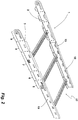
- a designed as an adapter cable support segment connector 1 has two, the length of the cable support connector 1 determining, continuous side rails, namely a right side rail 2 and a left side rail 3. As a result of their spacing take hold or limit the two side rails 2, 3 located between them cable management room one.
- the side rails 2, 3 are connected by a serving as a rung 4 bottom part.
- the Jardintragsegmentverbinder 1 is due to the design of the side rails 2, 3 in five successive or juxtaposed sections 5 - 9 divided.
- the individual sections 5 - 9 are separated from each other by kinks. These are identified by the rows of holes arranged between each two adjacent sections.
- the sections 5 and 9 serve as connection sections for mechanically connecting the connector 1 to a cable support segment. These are addressed below as connection sections.
- the rung 4 is located in the support section 7.
- the sections 6 and 8 are designed as setup sections.
- the two side rails 2, 3 are identical. In the following, the side rail 3 is described. These embodiments thus apply equally to the side rail 2.
- the side rail 3 is designed mirror-symmetrically with respect to the longitudinal extent of the connector 1 with respect to the center of its support portion indicated by the rung 4.
- the side member 3 associated portion through which the connection portion 5 is mitge is characterized by a hole pattern 10.
- This breadboard 10 serves to pass one or more fasteners when the cable support segment connector 1 is to be connected to the side rail of a cable support segment to be connected to this.
- the breadboard has openings at the ends of the openings, so that this end can be used as part of a joint connector.
- At the lower end of this part of the side rail 3 is a protruding in the direction of the side rail 2 flange 11. Through this, the part of the side rail 3, which forms the connection section 5, stabilized for a.
- the flange 11 serves for engaging under a bottom part or a lower flange of a cable support segment to be connected
- a kink K 1 Separated by a kink K 1 is adjacent to the above-described part of the side member 3 of the part of the side member 3, which is the Einrichteabrough 6 associated.
- This part of the side member 3 also carries on the underside a flange 11 corresponding flange. On the upper side, this part of the side member 3 has an eye 13.
- the kink K 1 is formed by a row of holes 14 in the illustrated embodiment.
- the row of holes 14, wherein in the illustrated embodiment, two holes form this row of holes extending in the direction of the height of the side member 3 and thus in the vertical direction.
- This extension defines the bending axis at which the portion of the side member 3 associated with the connection section 5 can be adjusted by bending or bending relative to the part associated with the installation section 6.
- a second kink K 2 separates the Einrichteabrough 6 associated part of the side member 3 of the part which is the support portion 7 associated.
- the kink K 2 is the same structure as the kink K 1 .
- the portion of the side member 3 associated with the support section 7 also has on the underside a flange 15 protruding to the side member 2 and an eye 16 on the top side.
- the flanges 11, 12, 15 and the eyes 13, 16 each have a notch or release on their sides facing each other on. As a result, an adjustment of the portion 6 associated portion or the portion 5 associated portion of the side member 3 in the cable management space inside is not hindered.
- the rung 4 is placed and secured thereto.
- the rung 4 is connected to the flange 15 with a projection welding.
- the rung 4 is such as used by cable ladders.
- these parts of the side rails 2, 3 are kept parallel to each other in each case due to the rigid connection between the rung 4 and the two parts of the side rails 2, 3.
- the side rails 2, 3 of the Jardintragsementverbinders 1 are parallel over their entire extent.
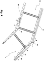
- FIG. 2 shows the cable support segment connector 1 in such an application.
- a cable support segment 17 Connected to the cable support segment connector 1 in the region of its connection section 6, a cable support segment 17, which is designed in the illustrated embodiment as a cable conductor.
- the cable support segment 17 and the other cable support segments described in the following figures are shown with only a portion of their total extension. It is clear from this representation that the flanges 11, 12 associated with the connection sections and the setup sections engage under a corresponding flange of the cable support segment 17, while the eyes 13 engage over the eyes of the side rails 18, 19 of the cable support segment 17.
- the sections of the side rails 2, 3 between them form a receptacle for the end portion of the cable support segment 17.
- a positive connection of the cable support segment 17 is provided to the cable support segment connector 1 in the transverse direction to the longitudinal extent.
- the connector 1 to the cable support segment 17 serve one or more a hole of the breadboard 10 by cross screws.
- a fixation in the longitudinal extent of the cable support segment 17 is achieved at the same time.
- sufficient electrical contact between the connector 1 and the cable support segment 17 is provided by the aforementioned fastening screws, so that the cable support system also meets the requirements of an overvoltage protection conductor or a ground conductor.
- the side rail 2 or 3 can be set up correspondingly at the kinks K 1 , K 2 , the adjustment section of the respective side rail 2 or 3 defines the jump distance or the change in the width of the connection section.
- FIG. 3 shows such an application of the cable support segment connector 1 in which the side rail 2 is set up to increase the width of the connection section 9. The end of another cable support segment engages with its side rails in this recording, which is limited by the Einrichteabêt 5 forming part of the side member 2 in the longitudinal direction.
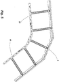
- FIG. 4 shows another application example in which the cable support segment connector 1 is adapted to form an elbow.
- the portion of the side member 3 associated with the connection portion 9 has been created in the cable management space with respect to the adjacent part of the setup portion at the kink K 3 separating the two portions.
- On the side rail 2 whose Eintreeilabsacrificing and its connecting part section at the kink K 4 are bent out of the cable guide space by the same angle adjustment.
- On the outer sides of the side rails 20, 21 of the connected to the terminal portion 9 cable support segment 22 are on the one hand the side rail 2 with its the connection portion 9 and the Einrichteabexcellent 8 associated parts and with respect to the side rail 3 of the connection portion 9 associated part.
- FIG. 5 shows the cable support segment connector 1 in a sheet design.
- the application example of FIG. 5 as well as the application example of FIG. 4 , From the application example of FIG. 4 differs that of the FIG. 4 only in that the connection to the cable support segment 17 is carried out according to the connection to the cable support segment 22. In this respect, two angle pieces are combined to form an arc by the connector 1 in this application.
- the cable support segment connector 1 can also be used to connect a cable support segment 23, which is larger in terms of its width, to the outside of a further cable support segment 24.
- a cable support segment 23 which is larger in terms of its width
- the parts of the side members 2, 3 associated with the one connection section, as well as the parts associated with the installation section, are interspersed 45 degrees outwards. By this measure, a corner formation is avoided.
- the connection of the cable support segment 23 to the cable support segment connector 1 takes place in the FIG. 3 described way.
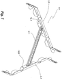
- FIG. 7 shows a cable support segment connector 1.1 according to another embodiment.
- the cable support segment connector 1.1 differs from the cable support segment connector 1 only in that its rung 4.1 are pivotally attached to the flanges 15.1 of the side rails 2.1 and 3.1, typically by means of a rivet.
- This allows a training in which the side rails 2.1, 2.3 no longer have to be parallel to each other in the region of the support section, but rather may be inclined, for example, as this in the FIG. 7 is shown. Due to the articulated connection of the rung 4.1 to the side rails 2.1, 3.1, the possibility of variant diversity is further increased.
Landscapes
- Engineering & Computer Science (AREA)
- Architecture (AREA)
- Civil Engineering (AREA)
- Structural Engineering (AREA)
- Laying Of Electric Cables Or Lines Outside (AREA)
- Installation Of Indoor Wiring (AREA)
- Electric Cable Arrangement Between Relatively Moving Parts (AREA)
- Details Of Indoor Wiring (AREA)
Priority Applications (3)
| Application Number | Priority Date | Filing Date | Title |
|---|---|---|---|
| PL15184231T PL2996214T3 (pl) | 2014-09-15 | 2015-09-08 | Złącze segmentu wspornika kabla wykonane jako adapter do systemu podtrzymywania kabli |
| RS20181293A RS57935B1 (sr) | 2014-09-15 | 2015-09-08 | Konektor delova nosača kablova kao adapter za sistem nosača kablova |
| HRP20181792TT HRP20181792T1 (hr) | 2014-09-15 | 2018-10-30 | Konektor segmenta za nošenje kablova kao adapter za sustav za nošenje kablova |
Applications Claiming Priority (1)
| Application Number | Priority Date | Filing Date | Title |
|---|---|---|---|
| DE202014104352.7U DE202014104352U1 (de) | 2014-09-15 | 2014-09-15 | Als Segment für ein Kabeltragsystem ausgeführter Kabeltragsegmentverbinder |
Publications (2)
| Publication Number | Publication Date |
|---|---|
| EP2996214A1 EP2996214A1 (de) | 2016-03-16 |
| EP2996214B1 true EP2996214B1 (de) | 2018-10-03 |
Family
ID=54105648
Family Applications (1)
| Application Number | Title | Priority Date | Filing Date |
|---|---|---|---|
| EP15184231.7A Active EP2996214B1 (de) | 2014-09-15 | 2015-09-08 | Als adapter für ein kabeltragsystem ausgeführter kabeltragsegmentverbinder |
Country Status (10)
| Country | Link |
|---|---|
| EP (1) | EP2996214B1 (lt) |
| DE (1) | DE202014104352U1 (lt) |
| DK (1) | DK2996214T3 (lt) |
| ES (1) | ES2694355T3 (lt) |
| HR (1) | HRP20181792T1 (lt) |
| HU (1) | HUE040672T2 (lt) |
| LT (1) | LT2996214T (lt) |
| PL (1) | PL2996214T3 (lt) |
| PT (1) | PT2996214T (lt) |
| RS (1) | RS57935B1 (lt) |
Families Citing this family (2)
| Publication number | Priority date | Publication date | Assignee | Title |
|---|---|---|---|---|
| DE102016012406A1 (de) * | 2016-10-18 | 2018-05-03 | Man Truck & Bus Ag | Technik zur Leitungsführung in einem Nutzfahrzeug |
| ES2918981T3 (es) * | 2018-03-16 | 2022-07-21 | Niedax Gmbh & Co Kg | Conector de guía de cables y método para conectar elementos de guía de cables |
Family Cites Families (6)
| Publication number | Priority date | Publication date | Assignee | Title |
|---|---|---|---|---|
| GB8725677D0 (en) * | 1987-11-03 | 1987-12-09 | Swifts Of Scarborough Ltd | Cable trays |
| GB2267605B (en) * | 1992-06-02 | 1996-01-03 | Associated Perforators And Wea | Improvements in or relating to cable tray bridging members |
| GB9214258D0 (en) * | 1992-07-04 | 1992-08-19 | Swifts Of Scarborough Ltd | Improvements relating to support systems for cables,service pipes and the like |
| ATE171818T1 (de) * | 1994-11-10 | 1998-10-15 | Stago Bv | Kanalsystem aus teilen wie kanäle und kupplungen für horizontale und vertikale verzweigungen von kabeln, drähten oder dergleichen |
| NO302262B1 (no) * | 1996-06-14 | 1998-02-09 | Oeglaend System As | Bend for kabelbane/kabelstige |
| GB2508101B (en) | 2012-04-30 | 2017-05-10 | Legrand Electric Ltd | Cable Tray Coupler |
-
2014
- 2014-09-15 DE DE202014104352.7U patent/DE202014104352U1/de not_active Expired - Lifetime
-
2015
- 2015-09-08 ES ES15184231.7T patent/ES2694355T3/es active Active
- 2015-09-08 HU HUE15184231A patent/HUE040672T2/hu unknown
- 2015-09-08 PT PT15184231T patent/PT2996214T/pt unknown
- 2015-09-08 LT LTEP15184231.7T patent/LT2996214T/lt unknown
- 2015-09-08 DK DK15184231.7T patent/DK2996214T3/en active
- 2015-09-08 EP EP15184231.7A patent/EP2996214B1/de active Active
- 2015-09-08 PL PL15184231T patent/PL2996214T3/pl unknown
- 2015-09-08 RS RS20181293A patent/RS57935B1/sr unknown
-
2018
- 2018-10-30 HR HRP20181792TT patent/HRP20181792T1/hr unknown
Non-Patent Citations (1)
| Title |
|---|
| None * |
Also Published As
| Publication number | Publication date |
|---|---|
| ES2694355T3 (es) | 2018-12-20 |
| DE202014104352U1 (de) | 2015-12-16 |
| EP2996214A1 (de) | 2016-03-16 |
| HRP20181792T1 (hr) | 2019-02-08 |
| LT2996214T (lt) | 2018-11-12 |
| RS57935B1 (sr) | 2019-01-31 |
| PT2996214T (pt) | 2018-11-20 |
| DK2996214T3 (en) | 2018-11-26 |
| HUE040672T2 (hu) | 2019-03-28 |
| PL2996214T3 (pl) | 2019-01-31 |
Similar Documents
| Publication | Publication Date | Title |
|---|---|---|
| EP2944854B1 (de) | Kabelleiter | |
| DE2647235C2 (de) | Distanzhalter für durch Schutzrohre hindurchgeführte Rohre | |
| EP0944786B1 (de) | Energiezuführungskette | |
| EP2996214B1 (de) | Als adapter für ein kabeltragsystem ausgeführter kabeltragsegmentverbinder | |
| EP2720330A1 (de) | Vorrichtung zum Verbinden von Kabelbahnabschnitten und Kabelbahn | |
| DE69011489T2 (de) | Verbindungselemente für Rückenlehnen mit dazugehörigen Sitzen. | |
| DE19810960A1 (de) | Trennsteg für Energieführungsketten | |
| EP2709221A1 (de) | Kabelbahn | |
| EP3851611A1 (de) | System umfassend zwei aufeinanderliegender liegende beläge und ein sicherungsmittel, verfahren zur verbindung zweier beläge und als spannfeder ausgebildetes sicherungsmittel | |
| DE8701832U1 (de) | Scharnierelement | |
| EP2446777B1 (de) | Knotenbauteil für ein Gestell für einen Tisch, Gestell für einen Tisch sowie Tisch | |
| DE102015101719B4 (de) | Energieführungseinrichtung und Anlage zur Werkstückbearbeitung | |
| DE3523741C2 (de) | Tragkonstruktion für abgehängte Decken | |
| DE202018101391U1 (de) | Stromleiteradapter zur Ausbildung einer stromführenden Verbindung mit einer Lochschiene eines Möbelstecksystems | |
| DE9010504U1 (de) | Deckenverkleidung | |
| DE2446927B2 (de) | Großflächenschalung mit verschieden gekrümmten Flächen | |
| DE102017000341A1 (de) | Leiterverbinder und Anordnung mit einem Leiterverbinder | |
| EP0116303B1 (de) | Als Gitterträger ausgebildeter Kalottenfussbalken | |
| DE19503429B4 (de) | Vorrichtung für das stirnseitige Verbinden von Kabelbahnen | |
| EP1670302A1 (de) | Rahmengestell | |
| DE102020113989A1 (de) | Vorrichtung zur Beeinflussung der Reibung einer Leitung an einem Trennsteg | |
| EP2808960B1 (de) | Vorrichtung zum Verbinden von Kabelbahnabschnitten und Kabelbahn | |
| DE2806940C3 (de) | Flächenkabelrost | |
| WO2024153803A1 (de) | Regalsystemverbinder | |
| DE202022102035U1 (de) | Kabeltragsegment |
Legal Events
| Date | Code | Title | Description |
|---|---|---|---|
| PUAI | Public reference made under article 153(3) epc to a published international application that has entered the european phase |
Free format text: ORIGINAL CODE: 0009012 |
|
| AK | Designated contracting states |
Kind code of ref document: A1 Designated state(s): AL AT BE BG CH CY CZ DE DK EE ES FI FR GB GR HR HU IE IS IT LI LT LU LV MC MK MT NL NO PL PT RO RS SE SI SK SM TR |
|
| AX | Request for extension of the european patent |
Extension state: BA ME |
|
| 17P | Request for examination filed |
Effective date: 20160607 |
|
| RBV | Designated contracting states (corrected) |
Designated state(s): AL AT BE BG CH CY CZ DE DK EE ES FI FR GB GR HR HU IE IS IT LI LT LU LV MC MK MT NL NO PL PT RO RS SE SI SK SM TR |
|
| STAA | Information on the status of an ep patent application or granted ep patent |
Free format text: STATUS: EXAMINATION IS IN PROGRESS |
|
| 17Q | First examination report despatched |
Effective date: 20171204 |
|
| GRAP | Despatch of communication of intention to grant a patent |
Free format text: ORIGINAL CODE: EPIDOSNIGR1 |
|
| STAA | Information on the status of an ep patent application or granted ep patent |
Free format text: STATUS: GRANT OF PATENT IS INTENDED |
|
| INTG | Intention to grant announced |
Effective date: 20180529 |
|
| GRAS | Grant fee paid |
Free format text: ORIGINAL CODE: EPIDOSNIGR3 |
|
| GRAA | (expected) grant |
Free format text: ORIGINAL CODE: 0009210 |
|
| STAA | Information on the status of an ep patent application or granted ep patent |
Free format text: STATUS: THE PATENT HAS BEEN GRANTED |
|
| AK | Designated contracting states |
Kind code of ref document: B1 Designated state(s): AL AT BE BG CH CY CZ DE DK EE ES FI FR GB GR HR HU IE IS IT LI LT LU LV MC MK MT NL NO PL PT RO RS SE SI SK SM TR |
|
| REG | Reference to a national code |
Ref country code: GB Ref legal event code: FG4D Free format text: NOT ENGLISH |
|
| REG | Reference to a national code |
Ref country code: CH Ref legal event code: EP Ref country code: AT Ref legal event code: REF Ref document number: 1049662 Country of ref document: AT Kind code of ref document: T Effective date: 20181015 |
|
| REG | Reference to a national code |
Ref country code: HR Ref legal event code: TUEP Ref document number: P20181792 Country of ref document: HR |
|
| REG | Reference to a national code |
Ref country code: CH Ref legal event code: NV Representative=s name: RENTSCH PARTNER AG, CH Ref country code: DE Ref legal event code: R096 Ref document number: 502015006205 Country of ref document: DE Ref country code: IE Ref legal event code: FG4D Free format text: LANGUAGE OF EP DOCUMENT: GERMAN |
|
| REG | Reference to a national code |
Ref country code: RO Ref legal event code: EPE |
|
| REG | Reference to a national code |
Ref country code: PT Ref legal event code: SC4A Ref document number: 2996214 Country of ref document: PT Date of ref document: 20181120 Kind code of ref document: T Free format text: AVAILABILITY OF NATIONAL TRANSLATION Effective date: 20181105 |
|
| REG | Reference to a national code |
Ref country code: NL Ref legal event code: FP |
|
| REG | Reference to a national code |
Ref country code: DK Ref legal event code: T3 Effective date: 20181119 |
|
| REG | Reference to a national code |
Ref country code: EE Ref legal event code: FG4A Ref document number: E016337 Country of ref document: EE Effective date: 20181102 |
|
| REG | Reference to a national code |
Ref country code: ES Ref legal event code: FG2A Ref document number: 2694355 Country of ref document: ES Kind code of ref document: T3 Effective date: 20181220 |
|
| REG | Reference to a national code |
Ref country code: HR Ref legal event code: T1PR Ref document number: P20181792 Country of ref document: HR |
|
| REG | Reference to a national code |
Ref country code: SK Ref legal event code: T3 Ref document number: E 29084 Country of ref document: SK |
|
| REG | Reference to a national code |
Ref country code: HU Ref legal event code: AG4A Ref document number: E040672 Country of ref document: HU |
|
| PG25 | Lapsed in a contracting state [announced via postgrant information from national office to epo] |
Ref country code: FI Free format text: LAPSE BECAUSE OF FAILURE TO SUBMIT A TRANSLATION OF THE DESCRIPTION OR TO PAY THE FEE WITHIN THE PRESCRIBED TIME-LIMIT Effective date: 20181003 Ref country code: IS Free format text: LAPSE BECAUSE OF FAILURE TO SUBMIT A TRANSLATION OF THE DESCRIPTION OR TO PAY THE FEE WITHIN THE PRESCRIBED TIME-LIMIT Effective date: 20190203 Ref country code: NO Free format text: LAPSE BECAUSE OF FAILURE TO SUBMIT A TRANSLATION OF THE DESCRIPTION OR TO PAY THE FEE WITHIN THE PRESCRIBED TIME-LIMIT Effective date: 20190103 |
|
| PG25 | Lapsed in a contracting state [announced via postgrant information from national office to epo] |
Ref country code: AL Free format text: LAPSE BECAUSE OF FAILURE TO SUBMIT A TRANSLATION OF THE DESCRIPTION OR TO PAY THE FEE WITHIN THE PRESCRIBED TIME-LIMIT Effective date: 20181003 Ref country code: GR Free format text: LAPSE BECAUSE OF FAILURE TO SUBMIT A TRANSLATION OF THE DESCRIPTION OR TO PAY THE FEE WITHIN THE PRESCRIBED TIME-LIMIT Effective date: 20190104 Ref country code: SE Free format text: LAPSE BECAUSE OF FAILURE TO SUBMIT A TRANSLATION OF THE DESCRIPTION OR TO PAY THE FEE WITHIN THE PRESCRIBED TIME-LIMIT Effective date: 20181003 |
|
| REG | Reference to a national code |
Ref country code: DE Ref legal event code: R097 Ref document number: 502015006205 Country of ref document: DE |
|
| PLBE | No opposition filed within time limit |
Free format text: ORIGINAL CODE: 0009261 |
|
| STAA | Information on the status of an ep patent application or granted ep patent |
Free format text: STATUS: NO OPPOSITION FILED WITHIN TIME LIMIT |
|
| PG25 | Lapsed in a contracting state [announced via postgrant information from national office to epo] |
Ref country code: SM Free format text: LAPSE BECAUSE OF FAILURE TO SUBMIT A TRANSLATION OF THE DESCRIPTION OR TO PAY THE FEE WITHIN THE PRESCRIBED TIME-LIMIT Effective date: 20181003 |
|
| 26N | No opposition filed |
Effective date: 20190704 |
|
| REG | Reference to a national code |
Ref country code: HR Ref legal event code: ODRP Ref document number: P20181792 Country of ref document: HR Payment date: 20190903 Year of fee payment: 5 |
|
| PG25 | Lapsed in a contracting state [announced via postgrant information from national office to epo] |
Ref country code: SI Free format text: LAPSE BECAUSE OF FAILURE TO SUBMIT A TRANSLATION OF THE DESCRIPTION OR TO PAY THE FEE WITHIN THE PRESCRIBED TIME-LIMIT Effective date: 20181003 |
|
| PGFP | Annual fee paid to national office [announced via postgrant information from national office to epo] |
Ref country code: NL Payment date: 20190923 Year of fee payment: 5 Ref country code: CZ Payment date: 20190828 Year of fee payment: 5 Ref country code: EE Payment date: 20190918 Year of fee payment: 5 Ref country code: RO Payment date: 20190830 Year of fee payment: 5 Ref country code: PT Payment date: 20190906 Year of fee payment: 5 Ref country code: SK Payment date: 20190828 Year of fee payment: 5 Ref country code: IT Payment date: 20190920 Year of fee payment: 5 Ref country code: FR Payment date: 20190924 Year of fee payment: 5 Ref country code: LT Payment date: 20190826 Year of fee payment: 5 |
|
| PGFP | Annual fee paid to national office [announced via postgrant information from national office to epo] |
Ref country code: HR Payment date: 20190903 Year of fee payment: 5 Ref country code: LV Payment date: 20190920 Year of fee payment: 5 Ref country code: RS Payment date: 20190903 Year of fee payment: 5 Ref country code: BG Payment date: 20190920 Year of fee payment: 5 |
|
| PGFP | Annual fee paid to national office [announced via postgrant information from national office to epo] |
Ref country code: CH Payment date: 20190924 Year of fee payment: 5 |
|
| PGFP | Annual fee paid to national office [announced via postgrant information from national office to epo] |
Ref country code: BE Payment date: 20190923 Year of fee payment: 5 Ref country code: ES Payment date: 20191023 Year of fee payment: 5 |
|
| PG25 | Lapsed in a contracting state [announced via postgrant information from national office to epo] |
Ref country code: TR Free format text: LAPSE BECAUSE OF FAILURE TO SUBMIT A TRANSLATION OF THE DESCRIPTION OR TO PAY THE FEE WITHIN THE PRESCRIBED TIME-LIMIT Effective date: 20181003 |
|
| PG25 | Lapsed in a contracting state [announced via postgrant information from national office to epo] |
Ref country code: MC Free format text: LAPSE BECAUSE OF FAILURE TO SUBMIT A TRANSLATION OF THE DESCRIPTION OR TO PAY THE FEE WITHIN THE PRESCRIBED TIME-LIMIT Effective date: 20181003 |
|
| PG25 | Lapsed in a contracting state [announced via postgrant information from national office to epo] |
Ref country code: IE Free format text: LAPSE BECAUSE OF NON-PAYMENT OF DUE FEES Effective date: 20190908 Ref country code: LU Free format text: LAPSE BECAUSE OF NON-PAYMENT OF DUE FEES Effective date: 20190908 |
|
| GBPC | Gb: european patent ceased through non-payment of renewal fee |
Effective date: 20190908 |
|
| PG25 | Lapsed in a contracting state [announced via postgrant information from national office to epo] |
Ref country code: GB Free format text: LAPSE BECAUSE OF NON-PAYMENT OF DUE FEES Effective date: 20190908 |
|
| REG | Reference to a national code |
Ref country code: HR Ref legal event code: PBON Ref document number: P20181792 Country of ref document: HR Effective date: 20200908 |
|
| REG | Reference to a national code |
Ref country code: EE Ref legal event code: MM4A Ref document number: E016337 Country of ref document: EE Effective date: 20200930 |
|
| PG25 | Lapsed in a contracting state [announced via postgrant information from national office to epo] |
Ref country code: RO Free format text: LAPSE BECAUSE OF NON-PAYMENT OF DUE FEES Effective date: 20200908 Ref country code: CZ Free format text: LAPSE BECAUSE OF NON-PAYMENT OF DUE FEES Effective date: 20200908 |
|
| REG | Reference to a national code |
Ref country code: CH Ref legal event code: PL |
|
| REG | Reference to a national code |
Ref country code: NL Ref legal event code: MM Effective date: 20201001 |
|
| REG | Reference to a national code |
Ref country code: SK Ref legal event code: MM4A Ref document number: E 29084 Country of ref document: SK Effective date: 20200908 |
|
| PG25 | Lapsed in a contracting state [announced via postgrant information from national office to epo] |
Ref country code: CY Free format text: LAPSE BECAUSE OF FAILURE TO SUBMIT A TRANSLATION OF THE DESCRIPTION OR TO PAY THE FEE WITHIN THE PRESCRIBED TIME-LIMIT Effective date: 20181003 Ref country code: RS Free format text: LAPSE BECAUSE OF NON-PAYMENT OF DUE FEES Effective date: 20200908 Ref country code: LV Free format text: LAPSE BECAUSE OF NON-PAYMENT OF DUE FEES Effective date: 20200908 |
|
| REG | Reference to a national code |
Ref country code: BE Ref legal event code: MM Effective date: 20200930 |
|
| PG25 | Lapsed in a contracting state [announced via postgrant information from national office to epo] |
Ref country code: NL Free format text: LAPSE BECAUSE OF NON-PAYMENT OF DUE FEES Effective date: 20201001 |
|
| REG | Reference to a national code |
Ref country code: LT Ref legal event code: MM4D Effective date: 20200908 |
|
| PG25 | Lapsed in a contracting state [announced via postgrant information from national office to epo] |
Ref country code: SK Free format text: LAPSE BECAUSE OF NON-PAYMENT OF DUE FEES Effective date: 20200908 Ref country code: PT Free format text: LAPSE BECAUSE OF NON-PAYMENT OF DUE FEES Effective date: 20210412 Ref country code: FR Free format text: LAPSE BECAUSE OF NON-PAYMENT OF DUE FEES Effective date: 20200930 Ref country code: HR Free format text: LAPSE BECAUSE OF NON-PAYMENT OF DUE FEES Effective date: 20200908 Ref country code: MT Free format text: LAPSE BECAUSE OF FAILURE TO SUBMIT A TRANSLATION OF THE DESCRIPTION OR TO PAY THE FEE WITHIN THE PRESCRIBED TIME-LIMIT Effective date: 20181003 Ref country code: EE Free format text: LAPSE BECAUSE OF NON-PAYMENT OF DUE FEES Effective date: 20200930 Ref country code: BG Free format text: LAPSE BECAUSE OF NON-PAYMENT OF DUE FEES Effective date: 20210331 |
|
| PG25 | Lapsed in a contracting state [announced via postgrant information from national office to epo] |
Ref country code: LI Free format text: LAPSE BECAUSE OF NON-PAYMENT OF DUE FEES Effective date: 20200930 Ref country code: BE Free format text: LAPSE BECAUSE OF NON-PAYMENT OF DUE FEES Effective date: 20200930 Ref country code: CH Free format text: LAPSE BECAUSE OF NON-PAYMENT OF DUE FEES Effective date: 20200930 |
|
| PG25 | Lapsed in a contracting state [announced via postgrant information from national office to epo] |
Ref country code: IT Free format text: LAPSE BECAUSE OF NON-PAYMENT OF DUE FEES Effective date: 20200908 Ref country code: LT Free format text: LAPSE BECAUSE OF NON-PAYMENT OF DUE FEES Effective date: 20200908 |
|
| REG | Reference to a national code |
Ref country code: AT Ref legal event code: MM01 Ref document number: 1049662 Country of ref document: AT Kind code of ref document: T Effective date: 20200908 |
|
| REG | Reference to a national code |
Ref country code: DE Ref legal event code: R082 Ref document number: 502015006205 Country of ref document: DE Representative=s name: HAVERKAMP PATENTANWAELTE PARTG MBB, DE |
|
| REG | Reference to a national code |
Ref country code: ES Ref legal event code: FD2A Effective date: 20220114 |
|
| PG25 | Lapsed in a contracting state [announced via postgrant information from national office to epo] |
Ref country code: AT Free format text: LAPSE BECAUSE OF NON-PAYMENT OF DUE FEES Effective date: 20200908 |
|
| PG25 | Lapsed in a contracting state [announced via postgrant information from national office to epo] |
Ref country code: ES Free format text: LAPSE BECAUSE OF NON-PAYMENT OF DUE FEES Effective date: 20200909 |
|
| PG25 | Lapsed in a contracting state [announced via postgrant information from national office to epo] |
Ref country code: MK Free format text: LAPSE BECAUSE OF FAILURE TO SUBMIT A TRANSLATION OF THE DESCRIPTION OR TO PAY THE FEE WITHIN THE PRESCRIBED TIME-LIMIT Effective date: 20181003 |
|
| P01 | Opt-out of the competence of the unified patent court (upc) registered |
Effective date: 20230529 |
|
| PGFP | Annual fee paid to national office [announced via postgrant information from national office to epo] |
Ref country code: PL Payment date: 20230821 Year of fee payment: 9 Ref country code: HU Payment date: 20230901 Year of fee payment: 9 Ref country code: DK Payment date: 20230921 Year of fee payment: 9 Ref country code: DE Payment date: 20230804 Year of fee payment: 9 |