EP2995959A1 - Laboratory sample distribution system and laboratory automation system - Google Patents
Laboratory sample distribution system and laboratory automation system Download PDFInfo
- Publication number
- EP2995959A1 EP2995959A1 EP15184193.9A EP15184193A EP2995959A1 EP 2995959 A1 EP2995959 A1 EP 2995959A1 EP 15184193 A EP15184193 A EP 15184193A EP 2995959 A1 EP2995959 A1 EP 2995959A1
- Authority
- EP
- European Patent Office
- Prior art keywords
- sample container
- laboratory
- distribution system
- recovery device
- sample
- Prior art date
- Legal status (The legal status is an assumption and is not a legal conclusion. Google has not performed a legal analysis and makes no representation as to the accuracy of the status listed.)
- Granted
Links
Images

Classifications
-
- G—PHYSICS
- G01—MEASURING; TESTING
- G01N—INVESTIGATING OR ANALYSING MATERIALS BY DETERMINING THEIR CHEMICAL OR PHYSICAL PROPERTIES
- G01N35/00—Automatic analysis not limited to methods or materials provided for in any single one of groups G01N1/00 - G01N33/00; Handling materials therefor
- G01N35/02—Automatic analysis not limited to methods or materials provided for in any single one of groups G01N1/00 - G01N33/00; Handling materials therefor using a plurality of sample containers moved by a conveyor system past one or more treatment or analysis stations
- G01N35/04—Details of the conveyor system
-
- B—PERFORMING OPERATIONS; TRANSPORTING
- B65—CONVEYING; PACKING; STORING; HANDLING THIN OR FILAMENTARY MATERIAL
- B65G—TRANSPORT OR STORAGE DEVICES, e.g. CONVEYORS FOR LOADING OR TIPPING, SHOP CONVEYOR SYSTEMS OR PNEUMATIC TUBE CONVEYORS
- B65G37/00—Combinations of mechanical conveyors of the same kind, or of different kinds, of interest apart from their application in particular machines or use in particular manufacturing processes
-
- B—PERFORMING OPERATIONS; TRANSPORTING
- B65—CONVEYING; PACKING; STORING; HANDLING THIN OR FILAMENTARY MATERIAL
- B65G—TRANSPORT OR STORAGE DEVICES, e.g. CONVEYORS FOR LOADING OR TIPPING, SHOP CONVEYOR SYSTEMS OR PNEUMATIC TUBE CONVEYORS
- B65G54/00—Non-mechanical conveyors not otherwise provided for
- B65G54/02—Non-mechanical conveyors not otherwise provided for electrostatic, electric, or magnetic
-
- B—PERFORMING OPERATIONS; TRANSPORTING
- B66—HOISTING; LIFTING; HAULING
- B66C—CRANES; LOAD-ENGAGING ELEMENTS OR DEVICES FOR CRANES, CAPSTANS, WINCHES, OR TACKLES
- B66C19/00—Cranes comprising trolleys or crabs running on fixed or movable bridges or gantries
- B66C19/005—Straddle carriers
-
- G—PHYSICS
- G01—MEASURING; TESTING
- G01N—INVESTIGATING OR ANALYSING MATERIALS BY DETERMINING THEIR CHEMICAL OR PHYSICAL PROPERTIES
- G01N35/00—Automatic analysis not limited to methods or materials provided for in any single one of groups G01N1/00 - G01N33/00; Handling materials therefor
- G01N35/02—Automatic analysis not limited to methods or materials provided for in any single one of groups G01N1/00 - G01N33/00; Handling materials therefor using a plurality of sample containers moved by a conveyor system past one or more treatment or analysis stations
- G01N35/04—Details of the conveyor system
- G01N2035/0401—Sample carriers, cuvettes or reaction vessels
- G01N2035/0406—Individual bottles or tubes
-
- G—PHYSICS
- G01—MEASURING; TESTING
- G01N—INVESTIGATING OR ANALYSING MATERIALS BY DETERMINING THEIR CHEMICAL OR PHYSICAL PROPERTIES
- G01N35/00—Automatic analysis not limited to methods or materials provided for in any single one of groups G01N1/00 - G01N33/00; Handling materials therefor
- G01N35/02—Automatic analysis not limited to methods or materials provided for in any single one of groups G01N1/00 - G01N33/00; Handling materials therefor using a plurality of sample containers moved by a conveyor system past one or more treatment or analysis stations
- G01N35/04—Details of the conveyor system
- G01N2035/0474—Details of actuating means for conveyors or pipettes
- G01N2035/0477—Magnetic
-
- G—PHYSICS
- G01—MEASURING; TESTING
- G01N—INVESTIGATING OR ANALYSING MATERIALS BY DETERMINING THEIR CHEMICAL OR PHYSICAL PROPERTIES
- G01N35/00—Automatic analysis not limited to methods or materials provided for in any single one of groups G01N1/00 - G01N33/00; Handling materials therefor
- G01N35/02—Automatic analysis not limited to methods or materials provided for in any single one of groups G01N1/00 - G01N33/00; Handling materials therefor using a plurality of sample containers moved by a conveyor system past one or more treatment or analysis stations
- G01N35/04—Details of the conveyor system
- G01N2035/0474—Details of actuating means for conveyors or pipettes
- G01N2035/0491—Position sensing, encoding; closed-loop control
- G01N2035/0494—Detecting or compensating piositioning errors
Definitions
- the invention relates to a laboratory sample distribution system, and to a laboratory automation system comprising such a laboratory sample distribution system.
- Laboratory sample distribution systems can be used to transport samples between laboratory stations.
- a laboratory sample distribution system together with such laboratory stations can be denoted as a laboratory automation system.
- a typical laboratory sample distribution system is described in document WO 2011/138448 A1 , wherein a plurality of sample container carriers is arranged on a transport plane in order to carry sample containers.
- Such laboratory sample distribution systems are typically used for medical samples, wherein it is important that samples are not subject to contamination while being analyzed or while being transported on the transport plane.
- laboratory sample distribution systems are complex technical systems that can show error conditions in exceptional cases, e.g. at occurrence of an earthquake. If manual action is required in order to bring the laboratory sample distribution system in a condition for further operation, the risk to contaminate samples and/or operating personal is high.
- the invention relates to a laboratory sample distribution system
- the recovery device By means of the recovery device it is possible to handle a sample container carrier or a sample container if an error condition has occurred. For example, if a sample container carrier cannot be moved by the movement means or drive means such as electromagnetic actuators, as will be described in further detail below, the recovery device can provide for a controlled movement of the sample container carrier. No manual action is needed.
- the recovery device can furthermore be equipped with specific handling means in order to perform certain tasks, as will be described in further detail below.
- the recovery device and/or a different part of the laboratory sample distribution system and/or the control device can also be equipped with specific sensors in order to fully or partially automatically recognize a specific situation and determine what action has to be taken in order to bring the laboratory sample distribution system in condition for further operation.
- the different part may be a stationary part of the laboratory sample distribution system, e. g. a cover housing for the transport plane with the sample container carriers.
- the recovery device and/or the different part of the laboratory sample distribution system and/or the control device may comprise a control unit being adapted to control the handling means and/or the drive means of the recovery device, in particular a controlled movement of the handling means.
- the control unit may be logically coupled to the specific sensors or be a part of them such that the control unit is adapted to fully or partially automatically recognize a specific situation and determine what action has to be taken in order to bring the laboratory sample distribution system in condition for further operation.
- Sample containers can typically be implemented as tubes made of transparent glass or plastic. Such sample containers can be easily put in a sample container carrier for transport between laboratory stations.
- the transport plane can also be denoted as a transport surface.
- a transport surface typically, it is possible to move the sample container carriers in two dimensions on top of the transport plane. This provides for a great flexibility in bringing the sample container carriers to specific positions.
- the handling means can be adapted to perform tasks like grabbing, lifting from the transport plane, rotating, pushing, pulling or other kinds of movement or handling. Specific implementations of the handling means will be discussed in greater detail below.
- a recovery device may also be adapted such that it is able to handle a plurality of sample container carriers or sample containers in parallel. This can diminish a time needed for a recovery operation.
- the laboratory sample distribution system may comprise at least one complementary energy source being adapted to provide the energy sources of the sample container carriers with energy.
- the at least one complementary energy source may be stationary arranged above or below the transport plane.
- the control device may be configured to control the at least one complementary energy source in order to control the energy provision of the energy sources of the sample container carriers.
- the at least one complementary energy source may comprise a charging station being adapted to charge the batteries of the sample container carriers.
- the at least one complementary energy source may comprise at least one induction coil being adapted to transfer energy to the induction coils of the sample container carriers.
- the sample container carriers typically move on top of the transport plane by means of the magnetic force being applied using the electromagnetic actuators.
- the control device can control movement of the sample container carriers easily.
- the drive means can be adapted to move the recovery device on the transport plane by making use of the same transport principle as the sample container carriers. Additionally or alternatively the drive means can be adapted to move the recovery device on the transport plane independently, i.e. self-driven. With the latter implementation, it is possible to move the recovery device on the transport plane even if e.g. the electromagnetic actuators or the control device are out of service.
- the drive means may comprise at least one magnetically active element, being adapted to interact with at least one electromagnetic actuator such that a magnetic drive force is applied to the recovery device.
- the magnetically active element may be adapted to interact with a magnetic field of the electromagnetic actuators.
- the magnetically active element may be a permanent magnet or an electromagnet or a combination thereof.
- the recovery device may be driven on the transport plane using the same drive principles as used for the sample container carriers, i.e. using the electromagnetic actuators arranged below the transport plane.
- the drive means may also comprise an electromagnet that may have a ferromagnetic core.
- the magnetically active element may comprise an electromagnetic actuator. This allows for a controlled application of a magnetic field by the recovery device, for example in order to be moved on the transport plane or to actively move on the transport plane. It should be noted that in some arrangements a combination of electromagnetic actuators in the recovery device, being energized and de-energized in a certain way, may lead to a specific movement of the recovery device on the transport plane. Therefore, the electromagnetic actuators of the recovery device can be arranged in a distance between each other that is different from the distance between the electromagnetic actuators of the laboratory sample distribution system.
- the drive means are adapted to move the recovery device on the transport plane independent from the movement means, in particular the electromagnetic actuators, of the laboratory sample distribution system, thus increasing the flexibility of the recovery device.
- the drive means may comprise a number of wheels or chains and a number of electric motors for driving the wheels or chains.
- the recovery device may move on the transport plane like a car.
- the wheels or chains may be driven in order to move the recovery device forward and the wheels may be steered in order to control the direction in which this recovery device moves.
- the wheels or chains may be driven differentially in order to control the direction in which the recovery device moves.
- the recovery device comprises communication means for communicating with the control device such that the recovery device is remote controllable by the control device.
- the control device may send drive commands to the recovery device in order to direct the recovery device to a location where action by the recovery device is needed.
- control device can control movement of the recovery device over the transport plane using the drive means.
- control device can control the recovery device in addition to controlling the sample container carriers.
- control device may control the handling means of the recovery device.
- the handling means comprise a rod, being adapted to mechanically couple a sample container carrier or a sample container to the recovery device.
- the rod may be equipped with a rake at an end of the rod.
- the recovery device may, for example, mechanically push or pull a sample container carrier that is unable to move on its own. This allows for evacuation of such a sample container carrier from the transport plane by means of the recovery device.
- the rod may be retractable and/or foldable. Especially, retracting and/or folding the rod may be done automatically, e.g. responsive to a command received from the control device. In this implementation, the rod may only be brought into a working position when a sample container carrier is actually to be connected, and does not restrict movement of the recovery device if not needed.
- the handling means comprise a crane device being positionable over a sample container carrier and/or a sample container and are adapted to grab and collect the sample container carrier and/or the sample container.
- the recovery device may move the sample container carrier or the sample container over the transport plane which can e.g. be done even if the sample container carrier or the sample container are in a position in which normal movement would not be possible. Such a situation could for example arise due to the sample container carrier or the sample container being in a tilted position or being damaged.
- the crane device comprises a claw being movable up and down.
- a claw can especially be used in order to grab and collect an item. It can be moved down in order to grab the item from its lower side, the claw may be tilted or moved horizontally in order to move at least partially below the item, and the item may be moved up together with the claw.
- the recovery device and/or a different part of the laboratory sample distribution system and/or the control device comprises environment scanning means being adapted to:
- the different part may be a stationary part of the laboratory sample distribution system, e. g. a cover housing for the transport plane with the sample container carriers.
- the environment scanning means may comprise or be logically coupled to the before mentioned control unit.
- the recovery device and/or the different part and/or the control device may autonomously determine a situation of a sample container carrier or a sample container, e.g. to autonomously determine what kind of fault has occurred and what action has to be done.
- the sample container carrier or the sample container may be recognized in order to grab and collect the sample container carrier or the sample container.
- Position and presence of a sample container or a sample container carrier may be determined in order to control recovery actions.
- a contamination may be detected in order to determine if a sample container carrier or a sample container may further move on the transport plane, or if the sample container carrier or the sample container have to be put temporarily out of service in order to avoid the risk of further spreading the contamination. Further, the contaminated parts of the transport plane may be set (temporarily) out of service.
- the environment scanning means comprise one or more of the following components:
- These environment scanning means can be used in order to assist the recovery device in managing typical fault situations in which its action is required.
- the afore-mentioned advantages of a recovery device can be utilized for a laboratory sample distribution system.
- the statements given with respect to the laboratory sample distribution system when discussing the recovery device above apply accordingly to the inventive laboratory sample distribution system.
- the recovery device for the laboratory sample distribution system all implementations and variations as discussed above can be used. Mentioned advantages apply accordingly.
- a number of fields is defined on the transport plane in a checkered manner, wherein each electromagnetic actuator is located below one of these fields such that in each second line of fields each second field is left blank, and each sample container carrier extends over one field.
- This arrangement of electromagnetic actuators has been proven advantageously in practice.
- a line having no blanks can preferably be used as transport line on which sample container carriers move.
- the neighboring lines having blanks provide for a certain distance to nearby moving sample container carriers.
- the recovery device extends over three fields in width and three fields in lengths. This provides for a sufficient stabilization of the recovery device and further provides for the possibility to move the recovery device such that a sample container carrier is positioned under elements of the recovery device. This allows, for example, for operation of the crane device mentioned above.
- the recovery device has four stilts being arranged such that each stilt abuts one field and that the stilts carry a horizontal beam extending over at least one field such that a sample container carrier having a sample container comprised in the sample container carrier can be placed below the beam.
- This implementation allows, for example, for moving the recovery device over a sample container carrier and a sample container that is to be handled.
- the above-mentioned crane device can be fixed at the beam and can be moved down from the beam.
- the invention further relates to a laboratory automation system, comprising a number, e.g. 2 or more, of a pre-analytical, analytical and/or post-analytical (laboratory) stations, and a laboratory sample distribution system as described above adapted to transport the sample container carriers and/or sample containers between the stations.
- the stations may be arranged adjacent to the laboratory sample distribution system.
- Pre-analytical stations may be adapted to perform any kind of pre-processing of samples, sample containers and/or sample container carriers.
- Analytical stations may be adapted to us a sample or part of the sample and a reagent to generate a measuring signal, the measuring signal indicating if and in which concentration, if any, an analyte is existing.
- Post-analytical stations may be adapted to perform any kind of post-processing of samples, sample containers and/or sample container carriers.
- the pre-analytical, analytical and/or post-analytical stations may comprise at least one of a decapping station, a recapping station, an aliquot station, a centrifugation station, an archiving station, a pipetting station, a sorting station, a tube type identification station, and a sample quality determining station.
- Fig. 1 shows a recovery device 200.
- the recovery device 200 comprises four stilts, namely a first stilt 210, a second stilt 212, a third stilt 214 and a fourth stilt 216.
- the first stilt 210 and the second stilt 212 are mechanically coupled by means of a first horizontal bearing, wherein the first stilt 210, the second stilt 212 and the first horizontal bearing form an inverse U.
- the third stilt 214 and the fourth stilt 216 are mechanically coupled by means of a second horizontal bearing, wherein the third stilt 214, the fourth stilt 216 and the second horizontal bearing form an inverse U.
- the inverse U is to be understood such that the U is opened to the bottom.
- a beam 220 is arranged between the horizontal bearings coupling the stilts 210, 212 and 214, 216, respectively.
- the beam 220 connects the two U-shaped arrangements of the stilts 210, 212, 214, 216 including the horizontal bearings.
- a space is provided below the beam 220.
- a space is left blank so that the recovery device 200 is able to move over an item being positioned on a transport plane.
- a handling device in form of a crane device 230 is arranged at the beam 220.
- the crane device 230 comprises a first claw 240 and a second claw 245, the two claws 240, 245 together forming a grabber.
- the two claws 240, 245 are attached to a cable 250.
- the cable 250 is wound on a cable drum 252, which is also positioned attached to the beam 220.
- the cable drum 252 is functionally coupled to an electric motor 254.
- the electric motor 254 is adapted to rotate the cable drum 252, so that the claws 240, 245 can be moved up and down.
- the claws 240, 245 can also be moved sideward, meaning parallel to a transport plane on which the recovery device 200 is moving.
- the recovery device 200 further comprises four pairs of wheels, such that the recovery device 200 can be moved autonomously on a transport plane.
- a first pair of wheels 270 is arranged at the bottom of the first stilt 210.
- a second pair of wheels 272 is arranged at the bottom of the second stilt 212.
- a third pair of wheels 274 is arranged at the bottom of the third stilt 214.
- a fourth pair of wheels 276 is arranged at the bottom of the fourth stilt 216.
- the recovery device 200 further comprises a camera 260, being directed to a position under the claws 240, 245. This allows the recovery device 200 to determine a situation, for example to see a sample container carrier and/or a sample container on the transport plane and to determine which action has to be taken in order to recover the sample container carrier and/or the sample container.
- the recovery device 200 further comprises communications means or a control unit or a control device 280.
- the control unit 280 is adapted to wirelessly communicate with a control device of a laboratory sample distribution system, which will be described further below with reference to fig. 2 . From the control device of the laboratory sample distribution system, the control unit 280 receives drive commands such that the recovery device 200 is remote controllable by the control device.
- the control unit 280 is adapted to control respective angular velocities of the wheels 270, 272, 274, 276 such that the recovery device 200 moves to a position as set by the control device.
- the camera 260 When the recovery device 200 arrives at a position at which an error condition has occurred, the camera 260 generates picture data regarding the condition in which a sample container carrier or a sample container is. For example, the camera 260 may determine that a sample container and a sample container carrier have been tilted over, which is a situation in which recovery action has to be performed.
- the control unit 280 receives respective image information from the camera 260 in order to make such a determination.
- the control unit 280 When the control unit 280 is aware of the situation, it moves the recovery device 200 just over any item that should be recovered, moves the claws 240, 245 down so that they can grab the item, moves the claws 240, 245 horizontally such that the item is actually grabbed, and moves the claws 240, 245 up in the direction of the beam 220. In such a condition, the recovery device 200 may bring the item to a safe location, for example to an edge of a transport plane in order to remove the item.
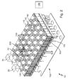
- Fig. 2 shows a laboratory sample distribution system 100 according to an embodiment of the invention.
- the laboratory sample distribution system 100 is part of a laboratory automation system 10 according to an embodiment of the invention, which further comprises a first laboratory station 20 and a second laboratory station 30.
- the laboratory sample distribution system 100 comprises a transport plane 110. Below the transport plane 110, a plurality of electromagnetic actuators 120 is arranged, wherein each electromagnetic actuator 120 comprises a ferromagnetic core 125.
- the electromagnetic actuators 120 are arranged in fields configured in a checkered manner, wherein in each second line of fields each second position is left blank, and wherein each other field has one electromagnetic actuator 120.
- Sample container carriers 140, 147 are placed on top of the transport plane 110.
- the sample container carriers 140, 147 carry a respective sample container 145 and 148. In a fault free condition, each sample container carrier 140, 147 extends over one field. It is to be understood that typically more than two sample container carriers are arranged on top of the transport plane 110.
- the transport plane 110 further comprises a plurality of Hall-sensors 130 that are used in order to determine the position of a sample container carrier 140, 147.
- Each sample container carrier 140, 147 comprises a magnetically active element in form of a permanent magnet is adapted to interact with a magnetic field generated by the electromagnetic actuators 120. In this manner, the sample container carriers 140, 147 can be moved over the transport plane 110.
- the laboratory sample distribution system 100 further comprises a control device 150 that is adapted to control the electromagnetic actuators 120.
- the control device 150 is adapted to energize and de-energize the electromagnetic actuators 120.
- the control device 150 is adapted to control movement of the sample container carriers 140, 147.
- the control device 150 is adapted to move the sample container carriers 140, 147 along specific paths, e.g. to one of the analyzers 20, 30.
- the sample container carrier 147 is tilted over.
- Such an error condition can occur due to accidents, for example at occurrence of an earthquake.
- the laboratory sample distribution system 100 comprises the recovery device 200 as described above with reference to fig. 1 .
- the recovery device 200 is adapted to move independently on the transport plane 110 using its wheels 270, 272, 274, 276. In the current situation, the recovery device 200 is adapted to move to the left side of the transport plane 110 and to grab and collect both the tilted over sample container carrier 147 and the tilted over sample container 148. Thus, the recovery device 200 puts the laboratory sample distribution system 100 in an error-free condition for further operation despite the occurrence of the accident, without the need of manual interaction. It is noted that the recovery device 200 extends over three fields in length and three fields in widths.
- the camera 260 of the recovery device 200 is adapted to detect that a blood contamination 149 has occurred on the transport plane 110 due to the tilted over sample container 148 in which a blood sample was contained.
- the control unit 280 of the recovery device 200 may ensure that the recovery device 200 does not move over the blood contamination 149, so that no contamination is spread over the transport plane (110).
Landscapes
- Engineering & Computer Science (AREA)
- Mechanical Engineering (AREA)
- General Health & Medical Sciences (AREA)
- Chemical & Material Sciences (AREA)
- Analytical Chemistry (AREA)
- Biochemistry (AREA)
- Physics & Mathematics (AREA)
- General Physics & Mathematics (AREA)
- Immunology (AREA)
- Pathology (AREA)
- Life Sciences & Earth Sciences (AREA)
- Health & Medical Sciences (AREA)
- Automatic Analysis And Handling Materials Therefor (AREA)
Abstract
Description
- The invention relates to a laboratory sample distribution system, and to a laboratory automation system comprising such a laboratory sample distribution system.
- Laboratory sample distribution systems can be used to transport samples between laboratory stations. A laboratory sample distribution system together with such laboratory stations can be denoted as a laboratory automation system.
- A typical laboratory sample distribution system is described in document
WO 2011/138448 A1 , wherein a plurality of sample container carriers is arranged on a transport plane in order to carry sample containers. Such laboratory sample distribution systems are typically used for medical samples, wherein it is important that samples are not subject to contamination while being analyzed or while being transported on the transport plane. - However, laboratory sample distribution systems are complex technical systems that can show error conditions in exceptional cases, e.g. at occurrence of an earthquake. If manual action is required in order to bring the laboratory sample distribution system in a condition for further operation, the risk to contaminate samples and/or operating personal is high.
- It is thus an object of the invention to provide a laboratory sample distribution system that minimizes the need for manual action. It is a further object of the invention to provide a laboratory automation system comprising such a laboratory sample distribution system.
- This is solved by a laboratory sample distribution system according to claim 1 and a laboratory automation system according to claim 15.
- The invention relates to a laboratory sample distribution system,
- wherein the laboratory sample distribution system comprises:
- a number of sample container carriers, being adapted to carry one or more sample containers,
- a transport plane, being adapted to support the sample container carriers,
- movement means being adapted to move a sample container carrier on top of the transport plane,
- a control device, being configured to control the movement of the sample container carriers on top of the transport plane by controlling the movement means such that the sample container carriers move along corresponding transport paths, and
a recovery device, wherein the recovery device comprises:- handling means adapted to handle a sample container carrier or a sample container, and
- drive means adapted to move the recovery device on the transport plane.
- By means of the recovery device it is possible to handle a sample container carrier or a sample container if an error condition has occurred. For example, if a sample container carrier cannot be moved by the movement means or drive means such as electromagnetic actuators, as will be described in further detail below, the recovery device can provide for a controlled movement of the sample container carrier. No manual action is needed. The recovery device can furthermore be equipped with specific handling means in order to perform certain tasks, as will be described in further detail below. The recovery device and/or a different part of the laboratory sample distribution system and/or the control device can also be equipped with specific sensors in order to fully or partially automatically recognize a specific situation and determine what action has to be taken in order to bring the laboratory sample distribution system in condition for further operation. The different part may be a stationary part of the laboratory sample distribution system, e. g. a cover housing for the transport plane with the sample container carriers. In detail, the recovery device and/or the different part of the laboratory sample distribution system and/or the control device may comprise a control unit being adapted to control the handling means and/or the drive means of the recovery device, in particular a controlled movement of the handling means. The control unit may be logically coupled to the specific sensors or be a part of them such that the control unit is adapted to fully or partially automatically recognize a specific situation and determine what action has to be taken in order to bring the laboratory sample distribution system in condition for further operation.
- Sample containers can typically be implemented as tubes made of transparent glass or plastic. Such sample containers can be easily put in a sample container carrier for transport between laboratory stations.
- The transport plane can also be denoted as a transport surface. Typically, it is possible to move the sample container carriers in two dimensions on top of the transport plane. This provides for a great flexibility in bringing the sample container carriers to specific positions.
- The handling means can be adapted to perform tasks like grabbing, lifting from the transport plane, rotating, pushing, pulling or other kinds of movement or handling. Specific implementations of the handling means will be discussed in greater detail below.
- It should be noted that a recovery device may also be adapted such that it is able to handle a plurality of sample container carriers or sample containers in parallel. This can diminish a time needed for a recovery operation.
- According to an embodiment of the invention each sample container carrier comprises
- at least one energy source to furnish drive power, e.g. a battery and/or an induction coil,
- at least one movement device, e.g. a wheel, with which the sample container carrier can move independently on the transport plane, and
- at least one drive device, e.g. an electric motor, to drive the at least one movement device, the at least one drive device being driven by the drive power,
- wherein the energy source, the at least one movement device and the at least one drive device form the movement means, and
- wherein the control device is configured to control the movement of the sample container carriers on top of the transport plane by controlling or driving the energy sources and/or the drive devices such that the sample container carriers move along corresponding transport paths.
- In addition the laboratory sample distribution system may comprise at least one complementary energy source being adapted to provide the energy sources of the sample container carriers with energy. The at least one complementary energy source may be stationary arranged above or below the transport plane. The control device may be configured to control the at least one complementary energy source in order to control the energy provision of the energy sources of the sample container carriers. E.g. the at least one complementary energy source may comprise a charging station being adapted to charge the batteries of the sample container carriers. Additionally or alternatively the at least one complementary energy source may comprise at least one induction coil being adapted to transfer energy to the induction coils of the sample container carriers.
- According to an embodiment of the invention
- each sample container carrier comprises at least one magnetically active device, e.g. in form of a permanent magnet,
- the movement means comprise a number of electromagnetic actuators, being stationary arranged below the transport plane, the electromagnetic actuators being adapted to move a sample container carrier on top of the transport plane by applying a magnetic force to the sample container carrier, and
- the control device is configured to control the movement of the sample container carriers on top of the transport plane by driving the electromagnetic actuators such that the sample container carriers move along corresponding transport paths.
- The sample container carriers typically move on top of the transport plane by means of the magnetic force being applied using the electromagnetic actuators. As the electromagnetic actuators are typically in a quite close proximity to each other, the control device can control movement of the sample container carriers easily.
- The drive means can be adapted to move the recovery device on the transport plane by making use of the same transport principle as the sample container carriers. Additionally or alternatively the drive means can be adapted to move the recovery device on the transport plane independently, i.e. self-driven. With the latter implementation, it is possible to move the recovery device on the transport plane even if e.g. the electromagnetic actuators or the control device are out of service.
- The drive means may comprise at least one magnetically active element, being adapted to interact with at least one electromagnetic actuator such that a magnetic drive force is applied to the recovery device. The magnetically active element may be adapted to interact with a magnetic field of the electromagnetic actuators. The magnetically active element may be a permanent magnet or an electromagnet or a combination thereof. The recovery device may be driven on the transport plane using the same drive principles as used for the sample container carriers, i.e. using the electromagnetic actuators arranged below the transport plane.
- The drive means may also comprise an electromagnet that may have a ferromagnetic core.
- The magnetically active element may comprise an electromagnetic actuator. This allows for a controlled application of a magnetic field by the recovery device, for example in order to be moved on the transport plane or to actively move on the transport plane. It should be noted that in some arrangements a combination of electromagnetic actuators in the recovery device, being energized and de-energized in a certain way, may lead to a specific movement of the recovery device on the transport plane. Therefore, the electromagnetic actuators of the recovery device can be arranged in a distance between each other that is different from the distance between the electromagnetic actuators of the laboratory sample distribution system.
- According to an embodiment, the drive means are adapted to move the recovery device on the transport plane independent from the movement means, in particular the electromagnetic actuators, of the laboratory sample distribution system, thus increasing the flexibility of the recovery device.
- For example, the drive means may comprise a number of wheels or chains and a number of electric motors for driving the wheels or chains. By means of such wheels or chains, the recovery device may move on the transport plane like a car. For example, the wheels or chains may be driven in order to move the recovery device forward and the wheels may be steered in order to control the direction in which this recovery device moves. Alternatively, the wheels or chains may be driven differentially in order to control the direction in which the recovery device moves.
- According to an implementation, the recovery device comprises communication means for communicating with the control device such that the recovery device is remote controllable by the control device. The control device may send drive commands to the recovery device in order to direct the recovery device to a location where action by the recovery device is needed.
- By means of the communication means, the control device can control movement of the recovery device over the transport plane using the drive means. Thus, the control device can control the recovery device in addition to controlling the sample container carriers. Additionally, by means of the communication means, the control device may control the handling means of the recovery device.
- According to an implementation, the handling means comprise a rod, being adapted to mechanically couple a sample container carrier or a sample container to the recovery device. The rod may be equipped with a rake at an end of the rod. Using such a rod, the recovery device may, for example, mechanically push or pull a sample container carrier that is unable to move on its own. This allows for evacuation of such a sample container carrier from the transport plane by means of the recovery device.
- The rod may be retractable and/or foldable. Especially, retracting and/or folding the rod may be done automatically, e.g. responsive to a command received from the control device. In this implementation, the rod may only be brought into a working position when a sample container carrier is actually to be connected, and does not restrict movement of the recovery device if not needed.
- According to an implementation, the handling means comprise a crane device being positionable over a sample container carrier and/or a sample container and are adapted to grab and collect the sample container carrier and/or the sample container. Thus, the recovery device may move the sample container carrier or the sample container over the transport plane which can e.g. be done even if the sample container carrier or the sample container are in a position in which normal movement would not be possible. Such a situation could for example arise due to the sample container carrier or the sample container being in a tilted position or being damaged.
- According to one implementation, the crane device comprises a claw being movable up and down. Such a claw can especially be used in order to grab and collect an item. It can be moved down in order to grab the item from its lower side, the claw may be tilted or moved horizontally in order to move at least partially below the item, and the item may be moved up together with the claw.
- According to an implementation, the recovery device and/or a different part of the laboratory sample distribution system and/or the control device comprises environment scanning means being adapted to:
- recognize a sample container carrier and/or a sample container, and/or
- determine if a sample container is contained in a sample container carrier, and/or
- determine if a sample container carrier and/or a sample container has tilted over, and/or
- determine if a sample container carrier and/or a sample container is contaminated.
- The different part may be a stationary part of the laboratory sample distribution system, e. g. a cover housing for the transport plane with the sample container carriers. The environment scanning means may comprise or be logically coupled to the before mentioned control unit.
- With such environment scanning means, it is possible for the recovery device and/or the different part and/or the control device to autonomously determine a situation of a sample container carrier or a sample container, e.g. to autonomously determine what kind of fault has occurred and what action has to be done. For example, the sample container carrier or the sample container may be recognized in order to grab and collect the sample container carrier or the sample container. Position and presence of a sample container or a sample container carrier may be determined in order to control recovery actions. A contamination may be detected in order to determine if a sample container carrier or a sample container may further move on the transport plane, or if the sample container carrier or the sample container have to be put temporarily out of service in order to avoid the risk of further spreading the contamination. Further, the contaminated parts of the transport plane may be set (temporarily) out of service.
- In typical implementations, the environment scanning means comprise one or more of the following components:
- a camera,
- a magnetic sensor,
- an RFID receiver,
- an ultrasonic sensor, and
- a haptic sensor.
- These environment scanning means can be used in order to assist the recovery device in managing typical fault situations in which its action is required.
- By means of the inventive laboratory sample distribution system, the afore-mentioned advantages of a recovery device can be utilized for a laboratory sample distribution system. The statements given with respect to the laboratory sample distribution system when discussing the recovery device above apply accordingly to the inventive laboratory sample distribution system. Regarding the recovery device for the laboratory sample distribution system, all implementations and variations as discussed above can be used. Mentioned advantages apply accordingly.
- In an embodiment a number of fields is defined on the transport plane in a checkered manner, wherein each electromagnetic actuator is located below one of these fields such that in each second line of fields each second field is left blank, and each sample container carrier extends over one field. This arrangement of electromagnetic actuators has been proven advantageously in practice. A line having no blanks can preferably be used as transport line on which sample container carriers move. The neighboring lines having blanks provide for a certain distance to nearby moving sample container carriers.
- In an embodiment the recovery device extends over three fields in width and three fields in lengths. This provides for a sufficient stabilization of the recovery device and further provides for the possibility to move the recovery device such that a sample container carrier is positioned under elements of the recovery device. This allows, for example, for operation of the crane device mentioned above.
- In an embodiment the recovery device has four stilts being arranged such that each stilt abuts one field and that the stilts carry a horizontal beam extending over at least one field such that a sample container carrier having a sample container comprised in the sample container carrier can be placed below the beam. This implementation allows, for example, for moving the recovery device over a sample container carrier and a sample container that is to be handled. For example, the above-mentioned crane device can be fixed at the beam and can be moved down from the beam.
- The invention further relates to a laboratory automation system, comprising a number, e.g. 2 or more, of a pre-analytical, analytical and/or post-analytical (laboratory) stations, and a laboratory sample distribution system as described above adapted to transport the sample container carriers and/or sample containers between the stations. The stations may be arranged adjacent to the laboratory sample distribution system.
- Pre-analytical stations may be adapted to perform any kind of pre-processing of samples, sample containers and/or sample container carriers.
- Analytical stations may be adapted to us a sample or part of the sample and a reagent to generate a measuring signal, the measuring signal indicating if and in which concentration, if any, an analyte is existing.
- Post-analytical stations may be adapted to perform any kind of post-processing of samples, sample containers and/or sample container carriers.
- The pre-analytical, analytical and/or post-analytical stations may comprise at least one of a decapping station, a recapping station, an aliquot station, a centrifugation station, an archiving station, a pipetting station, a sorting station, a tube type identification station, and a sample quality determining station.
- The invention will be described in detail with respect to the drawings illustrating embodiments of the invention, wherein
- Fig. 1
- schematically shows a recovery device, and
- Fig. 2
- schematically shows a laboratory automation system comprising a laboratory sample distribution system.
-
Fig. 1 shows arecovery device 200. Therecovery device 200 comprises four stilts, namely afirst stilt 210, asecond stilt 212, athird stilt 214 and afourth stilt 216. - The
first stilt 210 and thesecond stilt 212 are mechanically coupled by means of a first horizontal bearing, wherein thefirst stilt 210, thesecond stilt 212 and the first horizontal bearing form an inverse U. Accordingly, thethird stilt 214 and thefourth stilt 216 are mechanically coupled by means of a second horizontal bearing, wherein thethird stilt 214, thefourth stilt 216 and the second horizontal bearing form an inverse U. The inverse U is to be understood such that the U is opened to the bottom. - Between the horizontal bearings coupling the
stilts beam 220 is arranged. Thebeam 220 connects the two U-shaped arrangements of thestilts beam 220. Between two neighboringstilts recovery device 200 is able to move over an item being positioned on a transport plane. - A handling device in form of a
crane device 230 is arranged at thebeam 220. Thecrane device 230 comprises afirst claw 240 and asecond claw 245, the twoclaws - The two
claws cable 250. Thecable 250 is wound on acable drum 252, which is also positioned attached to thebeam 220. Thecable drum 252 is functionally coupled to anelectric motor 254. Theelectric motor 254 is adapted to rotate thecable drum 252, so that theclaws - The
claws recovery device 200 is moving. - The
recovery device 200 further comprises four pairs of wheels, such that therecovery device 200 can be moved autonomously on a transport plane. A first pair ofwheels 270 is arranged at the bottom of thefirst stilt 210. A second pair ofwheels 272 is arranged at the bottom of thesecond stilt 212. A third pair ofwheels 274 is arranged at the bottom of thethird stilt 214. A fourth pair ofwheels 276 is arranged at the bottom of thefourth stilt 216. With the pairs ofwheels recovery device 200 over a transport plane. For controlling a direction of movement, different angular velocities of the pairs ofwheels - The
recovery device 200 further comprises acamera 260, being directed to a position under theclaws recovery device 200 to determine a situation, for example to see a sample container carrier and/or a sample container on the transport plane and to determine which action has to be taken in order to recover the sample container carrier and/or the sample container. - The
recovery device 200 further comprises communications means or a control unit or acontrol device 280. Thecontrol unit 280 is adapted to wirelessly communicate with a control device of a laboratory sample distribution system, which will be described further below with reference tofig. 2 . From the control device of the laboratory sample distribution system, thecontrol unit 280 receives drive commands such that therecovery device 200 is remote controllable by the control device. Thecontrol unit 280 is adapted to control respective angular velocities of thewheels recovery device 200 moves to a position as set by the control device. - When the
recovery device 200 arrives at a position at which an error condition has occurred, thecamera 260 generates picture data regarding the condition in which a sample container carrier or a sample container is. For example, thecamera 260 may determine that a sample container and a sample container carrier have been tilted over, which is a situation in which recovery action has to be performed. Thecontrol unit 280 receives respective image information from thecamera 260 in order to make such a determination. - When the
control unit 280 is aware of the situation, it moves therecovery device 200 just over any item that should be recovered, moves theclaws claws claws beam 220. In such a condition, therecovery device 200 may bring the item to a safe location, for example to an edge of a transport plane in order to remove the item. -
Fig. 2 shows a laboratorysample distribution system 100 according to an embodiment of the invention. The laboratorysample distribution system 100 is part of alaboratory automation system 10 according to an embodiment of the invention, which further comprises afirst laboratory station 20 and asecond laboratory station 30. - The laboratory
sample distribution system 100 comprises atransport plane 110. Below thetransport plane 110, a plurality ofelectromagnetic actuators 120 is arranged, wherein eachelectromagnetic actuator 120 comprises aferromagnetic core 125. Theelectromagnetic actuators 120 are arranged in fields configured in a checkered manner, wherein in each second line of fields each second position is left blank, and wherein each other field has oneelectromagnetic actuator 120. -
Sample container carriers transport plane 110. Thesample container carriers respective sample container sample container carrier transport plane 110. - The
transport plane 110 further comprises a plurality of Hall-sensors 130 that are used in order to determine the position of asample container carrier - Each
sample container carrier electromagnetic actuators 120. In this manner, thesample container carriers transport plane 110. - The laboratory
sample distribution system 100 further comprises acontrol device 150 that is adapted to control theelectromagnetic actuators 120. Thecontrol device 150 is adapted to energize and de-energize theelectromagnetic actuators 120. Thus, thecontrol device 150 is adapted to control movement of thesample container carriers control device 150 is adapted to move thesample container carriers analyzers - As depicted, the
sample container carrier 147 is tilted over. Such an error condition can occur due to accidents, for example at occurrence of an earthquake. - To address such an error condition, the laboratory
sample distribution system 100 comprises therecovery device 200 as described above with reference tofig. 1 . - The
recovery device 200 is adapted to move independently on thetransport plane 110 using itswheels recovery device 200 is adapted to move to the left side of thetransport plane 110 and to grab and collect both the tilted oversample container carrier 147 and the tilted oversample container 148. Thus, therecovery device 200 puts the laboratorysample distribution system 100 in an error-free condition for further operation despite the occurrence of the accident, without the need of manual interaction. It is noted that therecovery device 200 extends over three fields in length and three fields in widths. - The
camera 260 of therecovery device 200 is adapted to detect that ablood contamination 149 has occurred on thetransport plane 110 due to the tilted oversample container 148 in which a blood sample was contained. Thus, thecontrol unit 280 of therecovery device 200 may ensure that therecovery device 200 does not move over theblood contamination 149, so that no contamination is spread over the transport plane (110).
Claims (15)
- Laboratory sample distribution system (100) comprising:- a number of sample container carriers (140, 147) being adapted to carry one or more sample containers (145, 148),- a transport plane (110) being adapted to support the sample container carriers (140, 147),- movement means (120) being adapted to move a sample container carrier (140, 147) on top of the transport plane (110),- a control device (150) being configured to control the movement of the sample container carriers (140, 147) on top of the transport plane (110) by controlling the movement means (120) such that the sample container carriers (140, 147) move along corresponding transport paths, and- a recovery device (200), wherein the recovery device (200) comprises:- handling means (230) being adapted to handle a sample container carrier (140, 147) or a sample container (145, 148), and- drive means (270, 272, 274, 276) being adapted to move the recovery device (200) on top of the transport plane (110).
- Laboratory sample distribution system (100) according to claim 1, characterized in that- each sample container carrier (140, 147) comprises at least one magnetically active device,- the movement means comprise a number of electro-magnetic actuators (120) being stationary arranged below the transport plane (110), the electro-magnetic actuators (120) being adapted to move a sample container carrier (140, 147) on top of the transport plane (110) by applying a magnetic force to the sample container carrier (140, 147), and- the control device (150) is configured to control the movement of the sample container carriers (140, 147) on top of the transport plane (110) by driving the electro-magnetic actuators (120) such that the sample container carriers (140, 147) move along corresponding transport paths.
- Laboratory sample distribution system (100) according to claim 2, characterized in that- the drive means comprise at least one magnetically active element being adapted to interact with at least one electromagnetic actuator (120) such that a magnetic drive force is applied to the recovery device (200).
- Laboratory sample distribution system (100) according to claim 3, characterized in that- the magnetically active element comprises an electro-magnetic actuator.
- Laboratory sample distribution system (100) according to one of the preceding claims, characterized in that- the drive means (270, 272, 274, 276) are adapted to move the recovery device (200) on top of the transport plane (110) independent from the movement means, in particular the electro-magnetic actuators (120), of the laboratory sample distribution system (100).
- Laboratory sample distribution system (100) according to one of the preceding claims, characterized in that- the recovery device (200) comprises communication means (280) for communicating with the control device (150) such that the recovery device (200) is remote controllable by the control device (150).
- Laboratory sample distribution system (100) according to one of the preceding claims, characterized in that- the handling means (230) comprise a rod being adapted to mechanically couple a sample container carrier (140, 147) or a sample container (145, 148) to the recovery device (200).
- Laboratory sample distribution system (100) according to claim 7, characterized in that- the rod of the recovery device (200) is retractable and/or foldable.
- Laboratory sample distribution system (100) according to one of the preceding claims, characterized in that- the handling means comprise a crane device (230) being positionable over a sample container carrier (140, 147) and/or a sample container (145, 148) and being adapted to grab and collect the sample container carrier (140, 147) and/or the sample container (145, 148), wherein the crane device (230) comprises a claw (240, 245) being vertically movable.
- Laboratory sample distribution system (100) according to one of the preceding claims, characterized in that- the recovery device (200) comprises environment scanning means (260) being adapted to:- recognize a sample container carrier (140, 147) and/or a sample container (145, 148), and/or- determine if a sample container (145, 148) is contained in a sample container carrier (140, 147), and/or- determine if a sample container carrier (140, 147) and/or a sample container (145, 148) has tilted over, and/or- determine if a sample container carrier (140, 147) and/or a sample container (145, 148) is contaminated.
- Laboratory sample distribution system (100) according to claim 10, characterized in that- the environment scanning means (260) comprise one or more of the following components:- a camera (260),- a magnetic sensor,- an RFID-receiver,- an ultrasonic sensor, and- a haptic sensor.
- Laboratory sample distribution system (100) according to one of claims 2 to 11, characterized in that- a number of fields is defined on the transport plane (110) in a checkered manner,- wherein the electromagnetic actuators (120) are located below a corresponding one of the fields such that in each second line of fields each second field is left blank, and- each sample container carrier (140, 147) extends over one of the fields.
- Laboratory sample distribution system (100) according to claim 12, characterized in that- the recovery device (200) extends over three fields in width and three fields in length.
- Laboratory sample distribution system (100) according to claim 12 or 13, characterized in that- the recovery device (200) has four stilts (210, 212, 214, 216) being arranged such that each stilt (210, 212, 214, 216) abuts one field, wherein the stilts (210, 212, 214, 216) carry a horizontal beam (220) extending over at least one field.
- Laboratory automation system (10), comprising:- a number of laboratory stations (20, 30), preferably in form of pre-analytical, analytical and/or post-analytical stations, and- a laboratory sample distribution system (100) according to one of the preceding claims, adapted to distribute sample container carriers (140, 147) between the laboratory stations (20, 30).
Priority Applications (1)
| Application Number | Priority Date | Filing Date | Title |
|---|---|---|---|
| EP15184193.9A EP2995959B1 (en) | 2014-09-12 | 2015-09-08 | Laboratory sample distribution system and laboratory automation system |
Applications Claiming Priority (2)
| Application Number | Priority Date | Filing Date | Title |
|---|---|---|---|
| EP14184623 | 2014-09-12 | ||
| EP15184193.9A EP2995959B1 (en) | 2014-09-12 | 2015-09-08 | Laboratory sample distribution system and laboratory automation system |
Publications (2)
| Publication Number | Publication Date |
|---|---|
| EP2995959A1 true EP2995959A1 (en) | 2016-03-16 |
| EP2995959B1 EP2995959B1 (en) | 2019-07-24 |
Family
ID=51542201
Family Applications (1)
| Application Number | Title | Priority Date | Filing Date |
|---|---|---|---|
| EP15184193.9A Active EP2995959B1 (en) | 2014-09-12 | 2015-09-08 | Laboratory sample distribution system and laboratory automation system |
Country Status (2)
| Country | Link |
|---|---|
| US (1) | US9952242B2 (en) |
| EP (1) | EP2995959B1 (en) |
Cited By (6)
| Publication number | Priority date | Publication date | Assignee | Title |
|---|---|---|---|---|
| EP3220147A1 (en) * | 2016-03-17 | 2017-09-20 | Siemens Healthcare Diagnostics Products GmbH | Warning system for potentially faulty measurement results in an automatic analyzer |
| EP3382397A1 (en) * | 2017-03-30 | 2018-10-03 | Roche Diagnostics GmbH | Laboratory sample distribution system and laboratory automation system |
| EP3396386A1 (en) * | 2017-04-28 | 2018-10-31 | Sysmex Corporation | Transporting apparatus, transporting method, and sample analysis system |
| EP3467513A1 (en) * | 2017-10-04 | 2019-04-10 | Roche Diagnostics GmbH | Detector for a laboratory liquid distribution system, detector system for a laboratory liquid distribution system, laboratory liquid distribution system, laboratory automation system and use of a detector |
| LU100790B1 (en) * | 2018-05-09 | 2019-11-12 | Stratec Biomedical Ag | Tube Carrier |
| WO2022233932A1 (en) | 2021-05-05 | 2022-11-10 | F. Hoffmann-La Roche Ag | Monitoring device for monitoring a sample handling system |
Families Citing this family (60)
| Publication number | Priority date | Publication date | Assignee | Title |
|---|---|---|---|---|
| DE102010028769A1 (en) | 2010-05-07 | 2011-11-10 | Pvt Probenverteiltechnik Gmbh | System for transporting containers between different stations and container carriers |
| EP2589967A1 (en) | 2011-11-04 | 2013-05-08 | Roche Diagnostics GmbH | Laboratory sample distribution system and corresponding method of operation |
| EP2589968A1 (en) | 2011-11-04 | 2013-05-08 | Roche Diagnostics GmbH | Laboratory sample distribution system, laboratory system and method of operating |
| EP2589966A1 (en) | 2011-11-04 | 2013-05-08 | Roche Diagnostics GmbH | Laboratory sample distribution system and corresponding method of operation |
| DE102014202843B3 (en) | 2014-02-17 | 2014-11-06 | Roche Pvt Gmbh | Transport device, sample distribution system and laboratory automation system |
| DE102014202838B3 (en) | 2014-02-17 | 2014-11-06 | Roche Pvt Gmbh | Transport device, sample distribution system and laboratory automation system |
| EP2927163B1 (en) | 2014-03-31 | 2018-02-28 | Roche Diagnostics GmbH | Vertical conveyor, sample distribution system and laboratory automation system |
| EP2927167B1 (en) | 2014-03-31 | 2018-04-18 | F. Hoffmann-La Roche AG | Dispatch device, sample distribution system and laboratory automation system |
| EP2927168A1 (en) | 2014-03-31 | 2015-10-07 | Roche Diagniostics GmbH | Transport device, sample distribution system and laboratory automation system |
| EP2927695B1 (en) | 2014-03-31 | 2018-08-22 | Roche Diagniostics GmbH | Sample distribution system and laboratory automation system |
| EP2927625A1 (en) | 2014-03-31 | 2015-10-07 | Roche Diagniostics GmbH | Sample distribution system and laboratory automation system |
| EP2957914B1 (en) * | 2014-06-17 | 2018-01-03 | Roche Diagnostics GmbH | Laboratory sample distribution system and laboratory automation system |
| EP2977766A1 (en) | 2014-07-24 | 2016-01-27 | Roche Diagniostics GmbH | Laboratory sample distribution system and laboratory automation system |
| EP2995580A1 (en) | 2014-09-09 | 2016-03-16 | Roche Diagniostics GmbH | Laboratory sample distribution system and laboratory automation system |
| EP2995960B1 (en) | 2014-09-09 | 2020-07-15 | Roche Diagniostics GmbH | Laboratory sample distribution system and method for calibrating magnetic sensors |
| EP2995958A1 (en) | 2014-09-15 | 2016-03-16 | Roche Diagniostics GmbH | Method of operating a laboratory sample distribution system, laboratory sample distribution system and laboratory automation system |
| EP3006943B1 (en) | 2014-10-07 | 2020-04-22 | Roche Diagniostics GmbH | Module for a laboratory sample distribution system, laboratory sample distribution system and laboratory automation system |
| EP3016116A1 (en) | 2014-11-03 | 2016-05-04 | Roche Diagniostics GmbH | Printed circuit board arrangement, coil for a laboratory sample distribution system, laboratory sample distribution system and laboratory automation system |
| EP3070479B1 (en) | 2015-03-16 | 2019-07-03 | Roche Diagniostics GmbH | Transport carrier, laboratory cargo distribution system and laboratory automation system |
| EP3537160B1 (en) | 2015-03-23 | 2020-08-12 | Roche Diagnostics GmbH | Laboratory sample distribution system and laboratory automation system |
| EP3096146A1 (en) | 2015-05-22 | 2016-11-23 | Roche Diagniostics GmbH | Method of operating a laboratory sample distribution system, laboratory sample distribution system and laboratory automation system |
| EP3096145B1 (en) | 2015-05-22 | 2019-09-04 | Roche Diagniostics GmbH | Method of operating a laboratory automation system and laboratory automation system |
| EP3095739A1 (en) | 2015-05-22 | 2016-11-23 | Roche Diagniostics GmbH | Method of operating a laboratory sample distribution system, laboratory sample distribution system and laboratory automation system |
| EP3112874A1 (en) | 2015-07-02 | 2017-01-04 | Roche Diagnostics GmbH | Storage module, method of operating a laboratory automation system and laboratory automation system |
| EP3121603A1 (en) | 2015-07-22 | 2017-01-25 | Roche Diagnostics GmbH | Sample container carrier, laboratory sample distribution system and laboratory automation system |
| EP3139175B1 (en) | 2015-09-01 | 2021-12-15 | Roche Diagnostics GmbH | Laboratory cargo distribution system, laboratory automation system and method of operating a laboratory cargo distribution system |
| EP3153867B1 (en) | 2015-10-06 | 2018-11-14 | Roche Diagniostics GmbH | Method of configuring a laboratory automation system, laboratory sample distribution system and laboratory automation system |
| EP3153866A1 (en) | 2015-10-06 | 2017-04-12 | Roche Diagnostics GmbH | Method of determining a handover position and laboratory automation system |
| EP3156352B1 (en) | 2015-10-13 | 2019-02-27 | Roche Diagniostics GmbH | Laboratory sample distribution system and laboratory automation system |
| EP3156353B1 (en) | 2015-10-14 | 2019-04-03 | Roche Diagniostics GmbH | Method of rotating a sample container carrier, laboratory sample distribution system and laboratory automation system |
| EP3211430A1 (en) | 2016-02-26 | 2017-08-30 | Roche Diagnostics GmbH | Transport device with base plate modules |
| EP3211429A1 (en) | 2016-02-26 | 2017-08-30 | Roche Diagnostics GmbH | Transport device having a tiled driving surface |
| EP3211428A1 (en) | 2016-02-26 | 2017-08-30 | Roche Diagnostics GmbH | Transport device unit for a laboratory sample distribution system |
| CN109196363A (en) | 2016-06-03 | 2019-01-11 | 豪夫迈·罗氏有限公司 | Laboratory sample distribution system and laboratory automation system |
| EP3255519B1 (en) | 2016-06-09 | 2019-02-20 | Roche Diagniostics GmbH | Laboratory sample distribution system and method of operating a laboratory sample distribution system |
| EP3260867A1 (en) * | 2016-06-21 | 2017-12-27 | Roche Diagnostics GmbH | Method of setting a handover position and laboratory automation system |
| JP6734989B2 (en) * | 2016-07-21 | 2020-08-05 | シーメンス・ヘルスケア・ダイアグノスティックス・インコーポレーテッドSiemens Healthcare Diagnostics Inc. | Systems and methods for adjusting based on monitoring and maintenance of automation trucks |
| JP6752350B2 (en) | 2016-08-04 | 2020-09-09 | エフ.ホフマン−ラ ロシュ アーゲーF. Hoffmann−La Roche Aktiengesellschaft | Laboratory sample distribution system and laboratory automation system |
| EP3330717B1 (en) | 2016-12-01 | 2022-04-06 | Roche Diagnostics GmbH | Laboratory sample distribution system and laboratory automation system |
| EP3343232B1 (en) | 2016-12-29 | 2021-09-15 | Roche Diagnostics GmbH | Laboratory sample distribution system and laboratory automation system |
| EP3355065B1 (en) | 2017-01-31 | 2021-08-18 | Roche Diagnostics GmbH | Laboratory sample distribution system and laboratory automation system |
| EP3357842B1 (en) | 2017-02-03 | 2022-03-23 | Roche Diagnostics GmbH | Laboratory automation system |
| EP3410123B1 (en) | 2017-06-02 | 2023-09-20 | Roche Diagnostics GmbH | Method of operating a laboratory sample distribution system, laboratory sample distribution system and laboratory automation system |
| EP3428653B1 (en) | 2017-07-13 | 2021-09-15 | Roche Diagnostics GmbH | Method of operating a laboratory sample distribution system, laboratory sample distribution system and laboratory automation system |
| EP3457144B1 (en) | 2017-09-13 | 2021-10-20 | Roche Diagnostics GmbH | Sample container carrier, laboratory sample distribution system and laboratory automation system |
| EP3456415B1 (en) | 2017-09-13 | 2021-10-20 | Roche Diagnostics GmbH | Sample container carrier, laboratory sample distribution system and laboratory automation system |
| EP3537159B1 (en) | 2018-03-07 | 2022-08-31 | Roche Diagnostics GmbH | Method of operating a laboratory sample distribution system, laboratory sample distribution system and laboratory automation system |
| EP3540443B1 (en) * | 2018-03-16 | 2023-08-30 | Roche Diagnostics GmbH | Laboratory system, laboratory sample distribution system and laboratory automation system |
| DE102018211839A1 (en) * | 2018-07-17 | 2020-01-23 | Bausch + Ströbel Maschinenfabrik Ilshofen GmbH + Co. KG | transport system |
| EP3925911B1 (en) | 2020-06-19 | 2023-05-24 | Roche Diagnostics GmbH | Laboratory sample distribution system and corresponding method of operation |
| EP3940388B1 (en) | 2020-07-15 | 2024-04-10 | Roche Diagnostics GmbH | Laboratory sample distribution system and method for operating the same |
| EP4001923B1 (en) | 2020-11-23 | 2024-06-05 | Roche Diagnostics GmbH | Laboratory sample distribution system and laboratory automation system |
| US11747356B2 (en) | 2020-12-21 | 2023-09-05 | Roche Diagnostics Operations, Inc. | Support element for a modular transport plane, modular transport plane, and laboratory distribution system |
| JP7427114B2 (en) * | 2020-12-23 | 2024-02-02 | 株式会社日立ハイテク | Sample transport device and sample transport method |
| JP7422652B2 (en) * | 2020-12-24 | 2024-01-26 | 株式会社日立ハイテク | Sample transport device |
| WO2023285637A1 (en) | 2021-07-16 | 2023-01-19 | Roche Diagnostics Gmbh | Transfer device for transferring sample containers in a sample handling system |
| DE102022113005A1 (en) * | 2022-05-24 | 2023-11-30 | Syntegon Technology Gmbh | Transport system for sterile tubes and use of a transport system |
| IT202200018624A1 (en) * | 2022-09-13 | 2024-03-13 | I M A Industria Macch Automatiche S P A In Sigla Ima S P A | EQUIPMENT FOR TRANSPORTING OBJECTS |
| CN117533795B (en) * | 2023-11-14 | 2026-03-10 | 中冶东方工程技术有限公司 | Sample transmission system |
| CN120553416B (en) * | 2025-07-30 | 2025-11-28 | 连云港中远海运化工储运有限公司 | A rapid transfer device for hazardous chemicals |
Citations (3)
| Publication number | Priority date | Publication date | Assignee | Title |
|---|---|---|---|---|
| WO2011138448A1 (en) | 2010-05-07 | 2011-11-10 | Pvt Probenverteiltechnik Gmbh | System for transporting containers between different stations, and the container carrier |
| EP2447701A2 (en) * | 2010-10-28 | 2012-05-02 | Sysmex Corporation | Sample processing system and method of processing sample |
| EP2589966A1 (en) * | 2011-11-04 | 2013-05-08 | Roche Diagnostics GmbH | Laboratory sample distribution system and corresponding method of operation |
Family Cites Families (230)
| Publication number | Priority date | Publication date | Assignee | Title |
|---|---|---|---|---|
| US3273727A (en) | 1966-09-20 | Load handling apparatus | ||
| US3653485A (en) | 1971-03-05 | 1972-04-04 | Transportation Technology | An air bearing conveyor |
| US3901656A (en) | 1972-08-24 | 1975-08-26 | American Monitor Corp | Apparatus and method for preparing and presenting serum chemistries for analyzation |
| DE2722865C2 (en) | 1977-05-20 | 1986-06-19 | Krupp Polysius Ag, 4720 Beckum | Pneumatic tube conveyor system for fine material samples |
| US4150666A (en) | 1977-06-27 | 1979-04-24 | Sherwood Medical Industries Inc. | Tube holder for blood collection tubes of different sizes |
| SU685591A1 (en) | 1977-08-01 | 1979-09-15 | Украинский Государственный Институт По Проектированию Металлургических Заводов | Tube mail despatch carrier |
| JPS56147209A (en) | 1980-04-16 | 1981-11-16 | Hitachi Kiden Kogyo Ltd | Automatic steering method for unattended carrying vehicle |
| US4544068A (en) | 1983-08-16 | 1985-10-01 | The United States Of America As Represented By The Administrator Of The National Aeronautics And Space Administration | Laboratory glassware rack for seismic safety |
| JPS60223481A (en) | 1984-04-18 | 1985-11-07 | Nippon Telegr & Teleph Corp <Ntt> | magnetic levitation guide device |
| JPH0761814B2 (en) | 1984-09-10 | 1995-07-05 | 三菱化学株式会社 | Carrier |
| JPS6181323A (en) | 1984-09-27 | 1986-04-24 | Mitsubishi Chem Ind Ltd | Aligned object moving device |
| GB2165516B (en) | 1984-10-11 | 1988-08-17 | Norris & Co D C | A conveyor drive drum, and a conveyor incorporating the drum |
| JPS6194925A (en) | 1984-10-12 | 1986-05-13 | Mitsubishi Chem Ind Ltd | Transport equipment |
| JPS61217434A (en) | 1985-03-20 | 1986-09-27 | Mitsubishi Chem Ind Ltd | Conveying device |
| JPS61174031A (en) | 1985-01-29 | 1986-08-05 | Youichi Oohira | Conveying device aimed at divergence, using linear induction motor type x-y actuator |
| JPS62100161A (en) | 1985-10-23 | 1987-05-09 | Shin Etsu Chem Co Ltd | Planar motor |
| US4771237A (en) | 1986-02-19 | 1988-09-13 | Panametrics | Method and apparatus for calibrating a displacement probe using a polynomial equation to generate a displacement look-up table |
| JPH0338704Y2 (en) | 1986-04-30 | 1991-08-15 | ||
| JPS6331918A (en) | 1986-07-16 | 1988-02-10 | フエコ・エンジニア−ド・システムズ・インコ−ポレ−テツド | Rotatable and retractable vessel holder and conveyor thereof |
| JPS6348169A (en) | 1986-08-14 | 1988-02-29 | Fuji Elelctrochem Co Ltd | Piezoelectric actuator |
| JPH0239554Y2 (en) | 1986-11-15 | 1990-10-23 | ||
| JPS63290101A (en) | 1987-05-22 | 1988-11-28 | Toshiba Corp | Linear motor type conveyor system |
| JPH01148966A (en) | 1987-12-04 | 1989-06-12 | Hitachi Kiden Kogyo Ltd | Sample transport device |
| JPH01266860A (en) | 1988-04-19 | 1989-10-24 | Yukitaka Furukawa | Test tube holding tool permitting cooling of the test tube |
| JP2585747B2 (en) | 1988-09-21 | 1997-02-26 | 株式会社ダイフク | Transfer equipment using linear motor |
| JPH02163637A (en) | 1988-12-16 | 1990-06-22 | Fuji Photo Film Co Ltd | Liquid chemical analyzing device |
| DE3909786A1 (en) | 1989-03-24 | 1990-09-27 | Schlafhorst & Co W | Apparatus for transporting cops and tubes between planes changing in the course of transport |
| DE4011797C2 (en) | 1989-06-10 | 1998-02-12 | Schlafhorst & Co W | Transport system for an automatic textile machine for the controlled guidance of pallets along specified transport routes |
| JPH03192013A (en) | 1989-12-21 | 1991-08-21 | Toshiba Corp | Indication device |
| JP2973133B2 (en) | 1990-09-19 | 1999-11-08 | 株式会社日立製作所 | Sample sorting device for clinical test |
| EP0529157A1 (en) | 1991-08-22 | 1993-03-03 | Mitsubishi Jukogyo Kabushiki Kaisha | Alternating current magnetic levitation transport system |
| JPH0569350A (en) | 1991-09-11 | 1993-03-23 | Toshiba Corp | Orbital robotic equipment maintenance equipment |
| JP3047571B2 (en) | 1991-11-20 | 2000-05-29 | 株式会社日立製作所 | Clinical test equipment |
| JPH05180847A (en) | 1991-12-31 | 1993-07-23 | Hiranuma Sangyo Kk | Automatic cycler for analyzer |
| DE69308493T2 (en) | 1992-06-29 | 1997-10-23 | Dade Int Inc | SUPPORT FOR TEST TUBES |
| EP0648698B1 (en) | 1992-07-07 | 1998-01-07 | Ebara Corporation | Magnetically levitated carrying apparatus |
| JPH0626806A (en) | 1992-07-08 | 1994-02-04 | Nippondenso Co Ltd | Displacement sensor |
| JPH0626808A (en) | 1992-07-09 | 1994-02-04 | Ebara Corp | Sensor target |
| EP0590222A1 (en) | 1992-09-30 | 1994-04-06 | STMicroelectronics S.r.l. | Magnetic position sensor |
| EP0601213A1 (en) | 1992-10-29 | 1994-06-15 | Hamilton Bonaduz AG | Transportdevice for goods |
| JPH06148198A (en) | 1992-11-05 | 1994-05-27 | Hitachi Ltd | Contamination preventing device for analyzing equipment |
| JPH06156730A (en) | 1992-11-13 | 1994-06-03 | Ebara Corp | Conveying device |
| JP3387951B2 (en) | 1993-01-19 | 2003-03-17 | 株式会社荏原製作所 | Substrate storage device |
| JPH07228345A (en) | 1994-02-14 | 1995-08-29 | Ebara Corp | Tunnel conveyer |
| JP2574126B2 (en) | 1994-02-28 | 1997-01-22 | 照明 伊藤 | Sample centrifugation method and apparatus |
| JPH07301637A (en) | 1994-04-29 | 1995-11-14 | Syst Sutatsuku:Kk | Testee conveyor device |
| US5636548A (en) | 1994-05-16 | 1997-06-10 | Tesoro Alaska Petroleum Company | Analog hall-effect liquid level detector and method |
| US5523131A (en) | 1994-11-01 | 1996-06-04 | Innovative Premiums Inc. | Self-propelled table novelty device |
| IL118232A (en) | 1995-05-15 | 2001-07-24 | Smithkline Beecham Corp | Vial holder |
| JP3112393B2 (en) | 1995-05-25 | 2000-11-27 | シャープ株式会社 | Color display |
| JPH0917848A (en) | 1995-06-30 | 1997-01-17 | Nikon Corp | Magnetically levitated stage |
| US5925956A (en) | 1995-06-30 | 1999-07-20 | Nikon Corporation | Stage construction incorporating magnetically levitated movable stage |
| US5735387A (en) * | 1995-07-14 | 1998-04-07 | Chiron Diagnostics Corporation | Specimen rack handling system |
| US5720377A (en) | 1995-07-14 | 1998-02-24 | Chiron Diagnostics Corporation | Magnetic conveyor system |
| EP0775650A1 (en) | 1995-11-24 | 1997-05-28 | André Dr. von Froreich | Conveyor system, especially for material carriers to be used in medical laboratories |
| US5788929A (en) | 1996-03-12 | 1998-08-04 | Nesti; Edmund D. | Sample temperature protection rack |
| US6191507B1 (en) | 1997-05-02 | 2001-02-20 | Ats Automation Tooling Systems Inc. | Modular conveyor system having multiple moving elements under independent control |
| JPH1159901A (en) | 1997-08-11 | 1999-03-02 | Murata Mach Ltd | Carrier moving device |
| JP3444760B2 (en) | 1997-09-11 | 2003-09-08 | 株式会社日立製作所 | Sample transport system |
| US6838051B2 (en) | 1999-05-03 | 2005-01-04 | Ljl Biosystems, Inc. | Integrated sample-processing system |
| US6141602A (en) | 1997-09-25 | 2000-10-31 | Hitachi, Ltd. | Specimen processing system |
| US5897090A (en) | 1997-11-13 | 1999-04-27 | Bayer Corporation | Puck for a sample tube |
| GB2331838A (en) | 1997-11-24 | 1999-06-02 | Coolbox | Portable,thermoelectric,temperature controlled receptacles. |
| JPH11264828A (en) | 1998-03-19 | 1999-09-28 | Hitachi Ltd | Sample transport system |
| JPH11304812A (en) | 1998-04-20 | 1999-11-05 | Hitachi Ltd | Sample processing system |
| DE19819813C2 (en) | 1998-05-04 | 2000-11-02 | Olympus Diagnostica Gmbh | Use of a laboratory primary sample distributor for archiving |
| JP3301965B2 (en) | 1998-05-19 | 2002-07-15 | アロカ株式会社 | Label reader |
| US6206176B1 (en) | 1998-05-20 | 2001-03-27 | Applied Komatsu Technology, Inc. | Substrate transfer shuttle having a magnetic drive |
| CA2273729A1 (en) | 1998-07-14 | 2000-01-14 | Bayer Corporation | Robotics for transporting containers and objects within an automated analytical instrument and service tool for servicing robotics |
| US6279728B1 (en) | 1998-07-20 | 2001-08-28 | Norbert G Jung | Electro-magnetic conveyor |
| JP3930977B2 (en) | 1998-07-31 | 2007-06-13 | 株式会社日立製作所 | Sample processing system |
| JP2000105243A (en) | 1998-09-29 | 2000-04-11 | Hitachi Ltd | Rack transport device |
| JP3668618B2 (en) | 1998-09-29 | 2005-07-06 | 株式会社日立製作所 | Automatic analyzer |
| JP4136187B2 (en) * | 1999-05-14 | 2008-08-20 | シスメックス株式会社 | Sample transfer device |
| US6062398A (en) | 1999-07-21 | 2000-05-16 | Thalmayr; Hermann | Insert for holding test tubes in a conveyor capsule of a pneumatic tube conveyor system |
| US6429016B1 (en) | 1999-10-01 | 2002-08-06 | Isis Pharmaceuticals, Inc. | System and method for sample positioning in a robotic system |
| JP3424623B2 (en) | 1999-10-29 | 2003-07-07 | 日立エンジニアリング株式会社 | Sample sorting device |
| EP1122194B1 (en) | 2000-02-01 | 2004-11-10 | Johnson & Johnson Vision Care, Inc. | Apparatus and method for automated warehousing |
| JP2001240245A (en) | 2000-03-01 | 2001-09-04 | Auto Cs Engineering Co Ltd | Conveying system and conveying device by compressed air |
| US20040050836A1 (en) | 2000-09-29 | 2004-03-18 | Nesbitt Geoffrey John | Assembly of an integrated vessel transporter and at least one reaction vessel and integrated vessel transporter for transporting a chemical substance |
| DE10050085C1 (en) | 2000-10-10 | 2001-10-31 | Jochem Koetting | Container closure element e.g. for analysis or reaction tube, provided as sphere, sphere segment, section or layer with paramagnetic core |
| US6825041B2 (en) | 2001-03-16 | 2004-11-30 | Beckman Coulter, Inc. | Method and system for automated immunochemistry analysis |
| AUPR854301A0 (en) | 2001-10-29 | 2001-11-29 | Martin Gessner Pty Ltd | Conveying apparatus |
| US6571934B1 (en) | 2001-11-14 | 2003-06-03 | Dade Behring Inc. | Bi-directional magnetic sample rack conveying system |
| JP3527904B2 (en) | 2002-02-28 | 2004-05-17 | 照明 伊藤 | Test tube holder |
| JP4105164B2 (en) | 2002-09-26 | 2008-06-25 | バイオパス・オートメーション・エル・エル・シー | Apparatus and method for automating the handling and embedding of tissue specimens |
| JP3675791B2 (en) | 2002-11-01 | 2005-07-27 | 照明 伊藤 | Bar coding device |
| TWI249574B (en) | 2002-11-19 | 2006-02-21 | Sanyo Electric Co | Preserving device |
| JP3765788B2 (en) | 2002-11-29 | 2006-04-12 | 照明 伊藤 | Sample dispensing system |
| GB2402481A (en) | 2003-06-04 | 2004-12-08 | Genial Genetic Solutions Ltd | Multi-well rotatable analyser |
| US7648835B2 (en) | 2003-06-06 | 2010-01-19 | Micronics, Inc. | System and method for heating, cooling and heat cycling on microfluidic device |
| JP3910157B2 (en) | 2003-06-11 | 2007-04-25 | ファナック株式会社 | Robot equipment |
| DE10340143A1 (en) | 2003-08-26 | 2005-03-31 | SSI Schäfer PEEM GmbH | Picking station and picking process |
| US20050079103A1 (en) | 2003-10-14 | 2005-04-14 | Merrit Jacobs | Moving evaporation control cover |
| US6971503B2 (en) | 2003-11-26 | 2005-12-06 | Cynthia Thompson | Conveyor belt cleaning apparatus |
| JP4680935B2 (en) | 2004-01-08 | 2011-05-11 | ジクスト、ベルンハルト | Transport container for cooling and holding frozen materials |
| US7078082B2 (en) | 2004-01-15 | 2006-07-18 | Sonoco Development, Inc. | Dual-functioning mechanism for startup during winding of web material and for splicing during unwinding |
| US7331474B2 (en) | 2004-03-05 | 2008-02-19 | Beckman Coulter, Inc. | Specimen-container rack for automated clinical instrument |
| US7028831B2 (en) | 2004-03-05 | 2006-04-18 | Beckman Coulter, Inc. | Magnetic specimen-transport system for automated clinical instrument |
| US7850914B2 (en) | 2004-03-05 | 2010-12-14 | Beckman Coulter, Inc. | Specimen-transport module for a multi-instrument clinical workcell |
| JP2005249740A (en) | 2004-03-08 | 2005-09-15 | Olympus Corp | Sample rack conveyer, and sample rack conveying method |
| US7382258B2 (en) | 2004-03-19 | 2008-06-03 | Applera Corporation | Sample carrier device incorporating radio frequency identification, and method |
| WO2005092632A1 (en) | 2004-03-27 | 2005-10-06 | Microrobot Co., Ltd. | Navigation system for position self control robot and floor materials for providing absolute coordinates used thereof |
| JP3905094B2 (en) | 2004-04-07 | 2007-04-18 | 株式会社アイディエス | Self-propelled specimen holder transport system |
| JP4098272B2 (en) | 2004-04-26 | 2008-06-11 | 株式会社アイディエス | Bar code reader for test tubes |
| US20060000296A1 (en) | 2004-07-02 | 2006-01-05 | Salter Jason P | Synchronization of sample and data collection |
| JPWO2006006730A1 (en) | 2004-07-15 | 2008-05-01 | 株式会社ニコン | Planar motor apparatus, stage apparatus, exposure apparatus, and device manufacturing method |
| US7862579B2 (en) | 2004-07-28 | 2011-01-04 | Ethicon Endo-Surgery, Inc. | Electroactive polymer-based articulation mechanism for grasper |
| JP4543181B2 (en) | 2004-12-20 | 2010-09-15 | 国立大学法人九州工業大学 | Non-contact transfer device by superconducting magnetic levitation |
| US7225915B2 (en) | 2005-04-05 | 2007-06-05 | Carol Lynn Kelly | Mountable cleaning apparatus for commercial conveyors |
| US20060246576A1 (en) | 2005-04-06 | 2006-11-02 | Affymetrix, Inc. | Fluidic system and method for processing biological microarrays in personal instrumentation |
| FR2888328B1 (en) * | 2005-07-08 | 2013-09-20 | Horiba Abx Sas | AUTOMATED PROCESS FOR THE PREPARATION OF TOTAL BLOOD SAMPLING ANALYSIS AND AUTOMATED DEVICE FOR ITS IMPLEMENTATION |
| US7566168B2 (en) | 2005-08-19 | 2009-07-28 | Shake Awake Products, LLC | Apparatus and method for determining the amount of time until a desired temperature is reached |
| US8346382B2 (en) | 2005-08-25 | 2013-01-01 | Coldtrack, Llc | Hierarchical sample storage system |
| US20070116611A1 (en) | 2005-11-14 | 2007-05-24 | Demarco Nicholas | Fraction collection system |
| JP4113891B2 (en) | 2005-12-20 | 2008-07-09 | ジェイ・エス・ケー株式会社 | Capacitance type detection device |
| CN201045617Y (en) | 2006-04-21 | 2008-04-09 | 北京赛科希德科技发展有限公司 | Test cup continuous conveyer for full-automatic cruor measurement |
| US7776270B2 (en) | 2006-04-25 | 2010-08-17 | Ecocap's S.R.L. | Resealer of test tubes for clinical analyses fed from ready-to-use containers of sealing tape |
| JP2007309675A (en) | 2006-05-16 | 2007-11-29 | Olympus Corp | Sample rack supply-and-recovery system |
| JP4586992B2 (en) | 2006-05-23 | 2010-11-24 | 株式会社ダイフク | Article processing equipment |
| JP2007322289A (en) | 2006-06-01 | 2007-12-13 | Olympus Corp | Conveyer |
| US7666366B2 (en) | 2006-07-10 | 2010-02-23 | Exxonmobil Chemical Patents Inc. | Internal loop reactor and Oxo process using same |
| DE102006032435A1 (en) | 2006-07-13 | 2008-01-17 | Sixt, Bernhard, Dr. | Transport container for keeping refrigerated frozen goods |
| JP2008058202A (en) | 2006-08-31 | 2008-03-13 | Ids Co Ltd | Specimen transfer system |
| JP4336360B2 (en) | 2006-09-20 | 2009-09-30 | 株式会社アイディエス | Sample pretreatment transport device |
| DE102007013237A1 (en) | 2007-03-15 | 2008-09-18 | Joint Analytical Systems Gmbh | storage system |
| DE102007014876B4 (en) | 2007-03-26 | 2010-04-08 | Kba-Metronic Aktiengesellschaft | transport system |
| ES2537079T3 (en) | 2007-04-16 | 2015-06-02 | Crisplant A/S | Classification system with a drive using a synchronous linear motor |
| US7681466B2 (en) | 2007-05-01 | 2010-03-23 | Siemens Healthcare Diagnostics Inc. | Programmable random access sample handler for use within and automated laboratory system |
| JP3133890U (en) | 2007-05-16 | 2007-07-26 | 株式会社日立ハイテクノロジーズ | Sample processing system |
| DE102007025822A1 (en) | 2007-06-02 | 2008-12-18 | Lars Bergmann | Combinable surface element with a plurality of controllable transducer elements |
| EP2153295B1 (en) | 2007-06-06 | 2014-11-05 | Path | Chemical temperature control |
| CN101680548A (en) | 2007-06-19 | 2010-03-24 | 株式会社开滋 | Shaft seal device and valve structure using the same |
| US8556564B2 (en) | 2007-06-26 | 2013-10-15 | Siemens Healthcare Diagnostics Inc. | Mobile sample storage and retrieval unit for a laboratory automated sample handling worksystem |
| KR101307859B1 (en) | 2007-07-19 | 2013-09-12 | 삼성전자주식회사 | Bio-chemical analyzer and method for controlling inside temperatures thereof |
| JP2009036643A (en) | 2007-08-01 | 2009-02-19 | Astec Corp:Kk | Control device for test tube input pattern to rack |
| JP2009062188A (en) | 2007-09-10 | 2009-03-26 | Tsubakimoto Chain Co | Sorting device using linear guide motor type x-y actuator |
| WO2009039122A2 (en) | 2007-09-17 | 2009-03-26 | Sequenom, Inc. | Integrated robotic sample transfer device |
| US20090128139A1 (en) | 2007-11-20 | 2009-05-21 | Drenth Joseph B | Magnet position locator |
| ITMI20072254A1 (en) | 2007-11-30 | 2009-06-01 | Dachi S R L | "PLANT FOR IDENTIFICATION, TRANSPORT AND AUTOMATIC ADDRESSING OF SAMPLES OF BIOLOGICAL MATERIAL" |
| ITMI20072255A1 (en) | 2007-11-30 | 2009-06-01 | Dachi S R L | "AUTOMATIC LOADING AND UNLOADING OF BIOLOGICAL MATERIAL TUBES IN A PNEUMATIC MAIL SYSTEM" |
| ITFI20070275A1 (en) * | 2007-12-07 | 2009-06-08 | Diesse Diagnostica Senese Spa | "DEVICE AND METHOD OF MICROBIOLOGICAL ANALYSIS OF BIOLOGICAL SAMPLES" |
| JP4863983B2 (en) | 2007-12-13 | 2012-01-25 | 株式会社堀場製作所 | Test tube holder and sample suction device |
| JP5258306B2 (en) | 2008-01-16 | 2013-08-07 | 株式会社ブリヂストン | Belt monitoring system |
| AT506886A1 (en) | 2008-05-16 | 2009-12-15 | Tgw Mechanics Gmbh | METHOD AND STORAGE SYSTEM FOR CONSOLIDATING SHIPPING UNITS |
| JP5140497B2 (en) | 2008-06-17 | 2013-02-06 | ベックマン コールター, インコーポレイテッド | Analysis apparatus and analysis method |
| US20110172128A1 (en) | 2008-09-12 | 2011-07-14 | Anthony Davies | Multi-well device |
| US8459462B2 (en) | 2008-10-10 | 2013-06-11 | Quest Diagnostics Investments Incorporated | System and method for sorting specimen |
| WO2010065145A1 (en) | 2008-12-05 | 2010-06-10 | Leap Technologies, Inc. | System for preparing samples for analysis using a shock freezer |
| US8616134B2 (en) | 2009-01-23 | 2013-12-31 | Magnemotion, Inc. | Transport system powered by short block linear synchronous motors |
| JP5250050B2 (en) | 2009-01-27 | 2013-07-31 | 株式会社日立ハイテクノロジーズ | Automatic analyzer and automatic analysis method |
| EP2403784B1 (en) | 2009-03-03 | 2013-07-24 | ATS Automation Tooling Systems Inc. | Multi-mode scroll cam conveyor system |
| JP5275119B2 (en) | 2009-04-06 | 2013-08-28 | 日本電子株式会社 | Automatic analyzer |
| CN102461330A (en) | 2009-05-05 | 2012-05-16 | 赛普拉斯半导体公司 | Spill-over detection method and system |
| GB2473868A (en) | 2009-09-28 | 2011-03-30 | Invitrogen Dynal As | Apparatus and method of automated processing of biological samples |
| WO2010132749A2 (en) | 2009-05-15 | 2010-11-18 | Biomerieux, Inc. | Automated transfer mechanism for microbial. detection apparatus |
| BE1018828A3 (en) | 2009-07-16 | 2011-09-06 | Praet Peter Van | INTELLIGENT RACK FOR SPECIMEN TUBES AND METHOD OF LOADING THE TUBES INTO THE RACK. |
| JP5481122B2 (en) | 2009-07-28 | 2014-04-23 | 株式会社日立ハイテクノロジーズ | Centrifuge |
| US7939484B1 (en) | 2009-10-27 | 2011-05-10 | Clariant International, Ltd. | Method for reducing the adhesion forces between hard surfaces and subsequently occurring soil |
| EP2327646B1 (en) | 2009-11-26 | 2012-02-08 | GLP systems GmbH | Switch in a branch of a transport path for laboratory samples in an analytical laboratory |
| JP5372732B2 (en) | 2009-12-28 | 2013-12-18 | シスメックス株式会社 | Sample analyzer and sample rack transport method |
| JP2013518251A (en) | 2010-01-21 | 2013-05-20 | シーメンス・ヘルスケア・ダイアグノスティックス・インコーポレーテッド | Magnetic conveyor system, apparatus and method including moving magnets |
| CN104597267B (en) | 2010-01-21 | 2016-11-23 | 希森美康株式会社 | Sample Analysis Device |
| US8141695B2 (en) | 2010-01-29 | 2012-03-27 | Ecolab Usa Inc. | Clean conveyor sensing system |
| US8240460B1 (en) | 2010-02-18 | 2012-08-14 | Michael James Bleau | Apparatus for cleaning a conveyor belt |
| US8915421B2 (en) | 2010-08-13 | 2014-12-23 | Lear Sirous Lavi | Transfer, link, bind, specimen tube barcode information to RFID specimen transport puck in a continuous moving binding process method |
| WO2012032503A1 (en) | 2010-09-07 | 2012-03-15 | University Of Limerick | A liquid droplet dispenser |
| DE102012000665A1 (en) | 2011-02-07 | 2012-08-09 | Sew-Eurodrive Gmbh & Co. Kg | sorter |
| IT1403938B1 (en) | 2011-02-16 | 2013-11-08 | Inpeco Ip Ltd Ora Inpeco Holding Ltd | INTERFACE SYSTEM BETWEEN A PNEUMATIC MAIL PLANT AND A SYSTEM OF FEEDING CONTAINERS OF BIOLOGICAL PRODUCTS TOWARDS A LABORATORY AUTOMATION PLANT. |
| US8624203B2 (en) | 2011-02-23 | 2014-01-07 | JLT & Associates, Inc. | Conveyor sterilization |
| US9547945B2 (en) | 2011-03-18 | 2017-01-17 | The Raymond Corporation | Integration of an autonomous industrial vehicle into an asset management system |
| PT2502675E (en) | 2011-03-25 | 2014-04-23 | Symbion Medical Systems S Rl | Container holder and container carrier |
| EP2518514B1 (en) | 2011-04-29 | 2014-06-18 | F. Hoffmann-La Roche AG | A method for operating an automated sample workcell |
| JP6014123B2 (en) | 2011-05-13 | 2016-10-25 | ベックマン コールター, インコーポレイテッド | Laboratory product transport elements and pathway arrays |
| CN103518137B (en) | 2011-05-13 | 2016-09-07 | 贝克曼考尔特公司 | System and method including laboratory product transport element |
| US8920720B2 (en) | 2011-06-03 | 2014-12-30 | Rushabh Instruments, Inc. | Rotary tissue processor with configurable stations |
| WO2012170636A1 (en) | 2011-06-07 | 2012-12-13 | Magnemotion, Inc. | Versatile control of a linear synchronous motor propulsion system |
| EP2755037B1 (en) | 2011-09-05 | 2024-12-25 | Hitachi High-Tech Corporation | Automatic analysis device |
| US10012664B2 (en) * | 2011-09-25 | 2018-07-03 | Theranos Ip Company, Llc | Systems and methods for fluid and component handling |
| EP2589967A1 (en) | 2011-11-04 | 2013-05-08 | Roche Diagnostics GmbH | Laboratory sample distribution system and corresponding method of operation |
| EP2589968A1 (en) | 2011-11-04 | 2013-05-08 | Roche Diagnostics GmbH | Laboratory sample distribution system, laboratory system and method of operating |
| KR20140091032A (en) | 2011-11-07 | 2014-07-18 | 베크만 컬터, 인코포레이티드 | Magnetic damping for specimen transport system |
| DE102011090044A1 (en) | 2011-12-28 | 2013-07-04 | Siemens Healthcare Diagnostics Products Gmbh | Transport system and method of operation |
| EP2799884B1 (en) | 2011-12-28 | 2018-04-25 | Hitachi High-Technologies Corporation | Holder for transferring test tube |
| EP2629100B1 (en) | 2012-02-15 | 2016-09-14 | GLP systems GmbH | Conveying system for material samples, in particular medical samples |
| JP2013172009A (en) | 2012-02-21 | 2013-09-02 | Hitachi Ltd | Flow soldering device and solder liquid surface adjustment method |
| US9664431B2 (en) | 2012-03-12 | 2017-05-30 | The World Egg Bank, Inc | Cryogenic sample holder |
| JP2013190400A (en) | 2012-03-15 | 2013-09-26 | Hitachi High-Technologies Corp | Autoanalyzer |
| EP2834648A4 (en) | 2012-04-04 | 2015-12-23 | Siemens Healthcare Diagnostics | METHOD FOR PROCESSING PRIORITY SAMPLES WHICH PRESERVE A PEPS PROCESS WAITING FILE |
| EP2847109B1 (en) | 2012-05-11 | 2017-12-20 | Siemens Healthcare Diagnostics Inc. | Method and system for transporting sample tubes |
| JP6177895B2 (en) | 2012-05-24 | 2017-08-09 | シーメンス・ヘルスケア・ダイアグノスティックス・インコーポレーテッドSiemens Healthcare Diagnostics Inc. | Non-contact optical encoding scheme for intelligent automation pack |
| US9952241B2 (en) | 2012-08-20 | 2018-04-24 | Siemens Healthcare Diagnostics Inc. | Methods and apparatus for ascertaining specimen and/or sample container characteristics while in transit |
| CA2887635C (en) | 2012-10-11 | 2021-01-26 | Siemens Healthcare Diagnostics Inc. | Automation maintenance carrier |
| CA2887643C (en) * | 2012-10-11 | 2021-06-08 | Siemens Healthcare Diagnostics Inc. | Modular workcells for lab automation |
| CA2890131C (en) | 2012-11-01 | 2020-12-29 | Siemens Healthcare Diagnostics Inc. | Multiple carrier and sleeve tray |
| CA2903013C (en) * | 2013-03-08 | 2021-05-11 | Siemens Healthcare Diagnostics Inc. | Tube characterization station |
| US8836797B1 (en) | 2013-03-14 | 2014-09-16 | Radiant-Zemax Holdings, LLC | Methods and systems for measuring and correcting electronic visual displays |
| CH708820A1 (en) | 2013-11-07 | 2015-05-15 | Tecan Trading Ag | Inkubationskassette. |
| EP2887071B1 (en) | 2013-12-19 | 2018-12-05 | F. Hoffmann-La Roche AG | Storage and supply of vessel holders |
| DE102014202838B3 (en) | 2014-02-17 | 2014-11-06 | Roche Pvt Gmbh | Transport device, sample distribution system and laboratory automation system |
| DE102014202843B3 (en) | 2014-02-17 | 2014-11-06 | Roche Pvt Gmbh | Transport device, sample distribution system and laboratory automation system |
| US10493457B2 (en) | 2014-03-28 | 2019-12-03 | Brooks Automation, Inc. | Sample storage and retrieval system |
| EP2927163B1 (en) | 2014-03-31 | 2018-02-28 | Roche Diagnostics GmbH | Vertical conveyor, sample distribution system and laboratory automation system |
| EP2927625A1 (en) | 2014-03-31 | 2015-10-07 | Roche Diagniostics GmbH | Sample distribution system and laboratory automation system |
| EP2927168A1 (en) | 2014-03-31 | 2015-10-07 | Roche Diagniostics GmbH | Transport device, sample distribution system and laboratory automation system |
| EP2927167B1 (en) | 2014-03-31 | 2018-04-18 | F. Hoffmann-La Roche AG | Dispatch device, sample distribution system and laboratory automation system |
| EP2927695B1 (en) | 2014-03-31 | 2018-08-22 | Roche Diagniostics GmbH | Sample distribution system and laboratory automation system |
| EP2957914B1 (en) | 2014-06-17 | 2018-01-03 | Roche Diagnostics GmbH | Laboratory sample distribution system and laboratory automation system |
| EP2977842A1 (en) | 2014-07-23 | 2016-01-27 | F. Hoffmann-La Roche AG | Laboratory sample distribution system and laboratory automation system |
| EP2977765A1 (en) | 2014-07-23 | 2016-01-27 | Roche Diagniostics GmbH | Sample container carrier, laboratory sample distribution system and laboratory automation system |
| EP2977766A1 (en) | 2014-07-24 | 2016-01-27 | Roche Diagniostics GmbH | Laboratory sample distribution system and laboratory automation system |
| EP2988134A1 (en) | 2014-08-21 | 2016-02-24 | Roche Diagniostics GmbH | Sample container carrier for a laboratory sample distribution system, laboratory sample distribution system and laboratory automation system |
| EP2995960B1 (en) | 2014-09-09 | 2020-07-15 | Roche Diagniostics GmbH | Laboratory sample distribution system and method for calibrating magnetic sensors |
| EP2995381A1 (en) | 2014-09-09 | 2016-03-16 | Roche Diagniostics GmbH | Set of sample container carriers for a laboratory sample distribution system, laboratory sample distribution system and laboratory automation system |
| EP2995580A1 (en) | 2014-09-09 | 2016-03-16 | Roche Diagniostics GmbH | Laboratory sample distribution system and laboratory automation system |
| EP2995958A1 (en) | 2014-09-15 | 2016-03-16 | Roche Diagniostics GmbH | Method of operating a laboratory sample distribution system, laboratory sample distribution system and laboratory automation system |
| EP3006943B1 (en) | 2014-10-07 | 2020-04-22 | Roche Diagniostics GmbH | Module for a laboratory sample distribution system, laboratory sample distribution system and laboratory automation system |
| EP3016116A1 (en) | 2014-11-03 | 2016-05-04 | Roche Diagniostics GmbH | Printed circuit board arrangement, coil for a laboratory sample distribution system, laboratory sample distribution system and laboratory automation system |
| EP3056907B1 (en) | 2015-02-11 | 2020-03-18 | F. Hoffmann-La Roche AG | Method and device for handling test tubes in a laboratory automation system |
| EP3070479B1 (en) | 2015-03-16 | 2019-07-03 | Roche Diagniostics GmbH | Transport carrier, laboratory cargo distribution system and laboratory automation system |
| EP3537160B1 (en) | 2015-03-23 | 2020-08-12 | Roche Diagnostics GmbH | Laboratory sample distribution system and laboratory automation system |
| EP3096145B1 (en) | 2015-05-22 | 2019-09-04 | Roche Diagniostics GmbH | Method of operating a laboratory automation system and laboratory automation system |
| EP3095739A1 (en) | 2015-05-22 | 2016-11-23 | Roche Diagniostics GmbH | Method of operating a laboratory sample distribution system, laboratory sample distribution system and laboratory automation system |
| EP3139175B1 (en) | 2015-09-01 | 2021-12-15 | Roche Diagnostics GmbH | Laboratory cargo distribution system, laboratory automation system and method of operating a laboratory cargo distribution system |
| EP3153867B1 (en) | 2015-10-06 | 2018-11-14 | Roche Diagniostics GmbH | Method of configuring a laboratory automation system, laboratory sample distribution system and laboratory automation system |
| EP3156352B1 (en) | 2015-10-13 | 2019-02-27 | Roche Diagniostics GmbH | Laboratory sample distribution system and laboratory automation system |
| EP3156353B1 (en) | 2015-10-14 | 2019-04-03 | Roche Diagniostics GmbH | Method of rotating a sample container carrier, laboratory sample distribution system and laboratory automation system |
| EP3211427A1 (en) | 2016-02-25 | 2017-08-30 | Roche Diagnostics GmbH | Sample container carrier |
| EP3211426A1 (en) | 2016-02-25 | 2017-08-30 | Roche Diagnostics GmbH | Sample container carrier |
| EP3260867A1 (en) | 2016-06-21 | 2017-12-27 | Roche Diagnostics GmbH | Method of setting a handover position and laboratory automation system |
-
2015
- 2015-09-02 US US14/843,418 patent/US9952242B2/en active Active
- 2015-09-08 EP EP15184193.9A patent/EP2995959B1/en active Active
Patent Citations (3)
| Publication number | Priority date | Publication date | Assignee | Title |
|---|---|---|---|---|
| WO2011138448A1 (en) | 2010-05-07 | 2011-11-10 | Pvt Probenverteiltechnik Gmbh | System for transporting containers between different stations, and the container carrier |
| EP2447701A2 (en) * | 2010-10-28 | 2012-05-02 | Sysmex Corporation | Sample processing system and method of processing sample |
| EP2589966A1 (en) * | 2011-11-04 | 2013-05-08 | Roche Diagnostics GmbH | Laboratory sample distribution system and corresponding method of operation |
Cited By (13)
| Publication number | Priority date | Publication date | Assignee | Title |
|---|---|---|---|---|
| US10359438B2 (en) | 2016-03-17 | 2019-07-23 | Siemens Healthcare Diagnostics Products Gmbh | Warning system for potentially erroneous measurement results in an automated analyzer |
| JP2017167147A (en) * | 2016-03-17 | 2017-09-21 | シーメンス ヘルスケア ダイアグノスティクス プロダクツ ゲゼルシヤフト ミツト ベシユレンクテル ハフツング | A system that warns of the possibility of erroneous measurement results in an automated analyzer |
| CN107202900A (en) * | 2016-03-17 | 2017-09-26 | 西门子医学诊断产品有限责任公司 | Warning system for latent fault measurement result in automatic analyzer |
| CN107202900B (en) * | 2016-03-17 | 2019-02-05 | 西门子医学诊断产品有限责任公司 | Warning system for potentially erroneous measurement results in automated analyzers |
| EP3220147A1 (en) * | 2016-03-17 | 2017-09-20 | Siemens Healthcare Diagnostics Products GmbH | Warning system for potentially faulty measurement results in an automatic analyzer |
| EP3382397A1 (en) * | 2017-03-30 | 2018-10-03 | Roche Diagnostics GmbH | Laboratory sample distribution system and laboratory automation system |
| EP3396386A1 (en) * | 2017-04-28 | 2018-10-31 | Sysmex Corporation | Transporting apparatus, transporting method, and sample analysis system |
| EP3467513A1 (en) * | 2017-10-04 | 2019-04-10 | Roche Diagnostics GmbH | Detector for a laboratory liquid distribution system, detector system for a laboratory liquid distribution system, laboratory liquid distribution system, laboratory automation system and use of a detector |
| LU100790B1 (en) * | 2018-05-09 | 2019-11-12 | Stratec Biomedical Ag | Tube Carrier |
| EP3570042A1 (en) | 2018-05-09 | 2019-11-20 | Stratec SE | Tube carrier |
| WO2022233932A1 (en) | 2021-05-05 | 2022-11-10 | F. Hoffmann-La Roche Ag | Monitoring device for monitoring a sample handling system |
| JP2024519309A (en) * | 2021-05-05 | 2024-05-10 | エフ ホフマン-ラ ロッシュ アクチェン ゲゼルシャフト | Monitoring device for monitoring a sample handling system - Patent Application 20070123633 |
| US12529706B2 (en) | 2021-05-05 | 2026-01-20 | Roche Diagnostics Operations, Inc. | Monitoring device for monitoring a sample handling system |
Also Published As
| Publication number | Publication date |
|---|---|
| US20160077120A1 (en) | 2016-03-17 |
| EP2995959B1 (en) | 2019-07-24 |
| US9952242B2 (en) | 2018-04-24 |
Similar Documents
| Publication | Publication Date | Title |
|---|---|---|
| US9952242B2 (en) | Laboratory sample distribution system and laboratory automation system | |
| EP3073270B1 (en) | Laboratory sample distribution system and laboratory automation system | |
| EP3191387B1 (en) | Laboratory sample distribution system and laboratory automation system | |
| EP3355064A1 (en) | Laboratory sample distribution system and laboratory automation system | |
| JP5993478B2 (en) | Vertical transport device, laboratory sample distribution system, and laboratory automation system | |
| US11511860B2 (en) | Systems for automated carriage of items for delivery | |
| CN105277728B (en) | Laboratory sample compartment system and laboratory automation system | |
| CN103547926B (en) | Laboratory product transport element and paths arrangement | |
| US20170168079A1 (en) | Set of sample container carriers for a laboratory sample distribution system, laboratory sample distribution system and laboratory automation system | |
| CN113859831A (en) | Material box carrying logistics robot | |
| EP3374772B1 (en) | Sample handling device and method for sample handling | |
| CN103518137A (en) | System and method including laboratory product transport element | |
| CN109564232B (en) | Laboratory sample distribution system and laboratory automation system | |
| JP7139253B2 (en) | Specimen carrier | |
| CN110694804A (en) | Reagent centrifugation system | |
| CN109704237A (en) | A kind of AGV traction forklift with intelligent decision identification perceptional function | |
| EP3112875A1 (en) | Transport device, laboratory sample distribution system and laboratory automation system | |
| EP3382397A1 (en) | Laboratory sample distribution system and laboratory automation system | |
| EP3073271A1 (en) | Method of operating a laboratory automation system and laboratory automation system | |
| US20220371828A1 (en) | Method and distribution system to move carriers on a transport plane | |
| HK1221012B (en) | Laboratory sample distribution system and laboratory automation system | |
| JP2021066592A (en) | Transportation control device, transportation control method and program | |
| JPH0138025B2 (en) |
Legal Events
| Date | Code | Title | Description |
|---|---|---|---|
| PUAI | Public reference made under article 153(3) epc to a published international application that has entered the european phase |
Free format text: ORIGINAL CODE: 0009012 |
|
| AK | Designated contracting states |
Kind code of ref document: A1 Designated state(s): AL AT BE BG CH CY CZ DE DK EE ES FI FR GB GR HR HU IE IS IT LI LT LU LV MC MK MT NL NO PL PT RO RS SE SI SK SM TR |
|
| AX | Request for extension of the european patent |
Extension state: BA ME |
|
| 17P | Request for examination filed |
Effective date: 20160913 |
|
| RBV | Designated contracting states (corrected) |
Designated state(s): AL AT BE BG CH CY CZ DE DK EE ES FI FR GB GR HR HU IE IS IT LI LT LU LV MC MK MT NL NO PL PT RO RS SE SI SK SM TR |
|
| STAA | Information on the status of an ep patent application or granted ep patent |
Free format text: STATUS: EXAMINATION IS IN PROGRESS |
|
| 17Q | First examination report despatched |
Effective date: 20181114 |
|
| GRAP | Despatch of communication of intention to grant a patent |
Free format text: ORIGINAL CODE: EPIDOSNIGR1 |
|
| STAA | Information on the status of an ep patent application or granted ep patent |
Free format text: STATUS: GRANT OF PATENT IS INTENDED |
|
| INTG | Intention to grant announced |
Effective date: 20190207 |
|
| GRAS | Grant fee paid |
Free format text: ORIGINAL CODE: EPIDOSNIGR3 |
|
| GRAA | (expected) grant |
Free format text: ORIGINAL CODE: 0009210 |
|
| STAA | Information on the status of an ep patent application or granted ep patent |
Free format text: STATUS: THE PATENT HAS BEEN GRANTED |
|
| AK | Designated contracting states |
Kind code of ref document: B1 Designated state(s): AL AT BE BG CH CY CZ DE DK EE ES FI FR GB GR HR HU IE IS IT LI LT LU LV MC MK MT NL NO PL PT RO RS SE SI SK SM TR |
|
| REG | Reference to a national code |
Ref country code: GB Ref legal event code: FG4D |
|
| REG | Reference to a national code |
Ref country code: CH Ref legal event code: EP |
|
| REG | Reference to a national code |
Ref country code: DE Ref legal event code: R096 Ref document number: 602015034177 Country of ref document: DE |
|
| REG | Reference to a national code |
Ref country code: AT Ref legal event code: REF Ref document number: 1158798 Country of ref document: AT Kind code of ref document: T Effective date: 20190815 |
|
| REG | Reference to a national code |
Ref country code: IE Ref legal event code: FG4D |
|
| REG | Reference to a national code |
Ref country code: NL Ref legal event code: MP Effective date: 20190724 |
|
| REG | Reference to a national code |
Ref country code: LT Ref legal event code: MG4D |
|
| REG | Reference to a national code |
Ref country code: AT Ref legal event code: MK05 Ref document number: 1158798 Country of ref document: AT Kind code of ref document: T Effective date: 20190724 |
|
| PG25 | Lapsed in a contracting state [announced via postgrant information from national office to epo] |
Ref country code: HR Free format text: LAPSE BECAUSE OF FAILURE TO SUBMIT A TRANSLATION OF THE DESCRIPTION OR TO PAY THE FEE WITHIN THE PRESCRIBED TIME-LIMIT Effective date: 20190724 Ref country code: PT Free format text: LAPSE BECAUSE OF FAILURE TO SUBMIT A TRANSLATION OF THE DESCRIPTION OR TO PAY THE FEE WITHIN THE PRESCRIBED TIME-LIMIT Effective date: 20191125 Ref country code: LT Free format text: LAPSE BECAUSE OF FAILURE TO SUBMIT A TRANSLATION OF THE DESCRIPTION OR TO PAY THE FEE WITHIN THE PRESCRIBED TIME-LIMIT Effective date: 20190724 Ref country code: SE Free format text: LAPSE BECAUSE OF FAILURE TO SUBMIT A TRANSLATION OF THE DESCRIPTION OR TO PAY THE FEE WITHIN THE PRESCRIBED TIME-LIMIT Effective date: 20190724 Ref country code: NL Free format text: LAPSE BECAUSE OF FAILURE TO SUBMIT A TRANSLATION OF THE DESCRIPTION OR TO PAY THE FEE WITHIN THE PRESCRIBED TIME-LIMIT Effective date: 20190724 Ref country code: BG Free format text: LAPSE BECAUSE OF FAILURE TO SUBMIT A TRANSLATION OF THE DESCRIPTION OR TO PAY THE FEE WITHIN THE PRESCRIBED TIME-LIMIT Effective date: 20191024 Ref country code: FI Free format text: LAPSE BECAUSE OF FAILURE TO SUBMIT A TRANSLATION OF THE DESCRIPTION OR TO PAY THE FEE WITHIN THE PRESCRIBED TIME-LIMIT Effective date: 20190724 Ref country code: AT Free format text: LAPSE BECAUSE OF FAILURE TO SUBMIT A TRANSLATION OF THE DESCRIPTION OR TO PAY THE FEE WITHIN THE PRESCRIBED TIME-LIMIT Effective date: 20190724 Ref country code: NO Free format text: LAPSE BECAUSE OF FAILURE TO SUBMIT A TRANSLATION OF THE DESCRIPTION OR TO PAY THE FEE WITHIN THE PRESCRIBED TIME-LIMIT Effective date: 20191024 |
|
| PG25 | Lapsed in a contracting state [announced via postgrant information from national office to epo] |
Ref country code: RS Free format text: LAPSE BECAUSE OF FAILURE TO SUBMIT A TRANSLATION OF THE DESCRIPTION OR TO PAY THE FEE WITHIN THE PRESCRIBED TIME-LIMIT Effective date: 20190724 Ref country code: IS Free format text: LAPSE BECAUSE OF FAILURE TO SUBMIT A TRANSLATION OF THE DESCRIPTION OR TO PAY THE FEE WITHIN THE PRESCRIBED TIME-LIMIT Effective date: 20191124 Ref country code: LV Free format text: LAPSE BECAUSE OF FAILURE TO SUBMIT A TRANSLATION OF THE DESCRIPTION OR TO PAY THE FEE WITHIN THE PRESCRIBED TIME-LIMIT Effective date: 20190724 Ref country code: ES Free format text: LAPSE BECAUSE OF FAILURE TO SUBMIT A TRANSLATION OF THE DESCRIPTION OR TO PAY THE FEE WITHIN THE PRESCRIBED TIME-LIMIT Effective date: 20190724 Ref country code: AL Free format text: LAPSE BECAUSE OF FAILURE TO SUBMIT A TRANSLATION OF THE DESCRIPTION OR TO PAY THE FEE WITHIN THE PRESCRIBED TIME-LIMIT Effective date: 20190724 Ref country code: GR Free format text: LAPSE BECAUSE OF FAILURE TO SUBMIT A TRANSLATION OF THE DESCRIPTION OR TO PAY THE FEE WITHIN THE PRESCRIBED TIME-LIMIT Effective date: 20191025 |
|
| PG25 | Lapsed in a contracting state [announced via postgrant information from national office to epo] |
Ref country code: TR Free format text: LAPSE BECAUSE OF FAILURE TO SUBMIT A TRANSLATION OF THE DESCRIPTION OR TO PAY THE FEE WITHIN THE PRESCRIBED TIME-LIMIT Effective date: 20190724 |
|
| PG25 | Lapsed in a contracting state [announced via postgrant information from national office to epo] |
Ref country code: DK Free format text: LAPSE BECAUSE OF FAILURE TO SUBMIT A TRANSLATION OF THE DESCRIPTION OR TO PAY THE FEE WITHIN THE PRESCRIBED TIME-LIMIT Effective date: 20190724 Ref country code: EE Free format text: LAPSE BECAUSE OF FAILURE TO SUBMIT A TRANSLATION OF THE DESCRIPTION OR TO PAY THE FEE WITHIN THE PRESCRIBED TIME-LIMIT Effective date: 20190724 Ref country code: RO Free format text: LAPSE BECAUSE OF FAILURE TO SUBMIT A TRANSLATION OF THE DESCRIPTION OR TO PAY THE FEE WITHIN THE PRESCRIBED TIME-LIMIT Effective date: 20190724 Ref country code: PL Free format text: LAPSE BECAUSE OF FAILURE TO SUBMIT A TRANSLATION OF THE DESCRIPTION OR TO PAY THE FEE WITHIN THE PRESCRIBED TIME-LIMIT Effective date: 20190724 |
|
| PG25 | Lapsed in a contracting state [announced via postgrant information from national office to epo] |
Ref country code: SM Free format text: LAPSE BECAUSE OF FAILURE TO SUBMIT A TRANSLATION OF THE DESCRIPTION OR TO PAY THE FEE WITHIN THE PRESCRIBED TIME-LIMIT Effective date: 20190724 Ref country code: SK Free format text: LAPSE BECAUSE OF FAILURE TO SUBMIT A TRANSLATION OF THE DESCRIPTION OR TO PAY THE FEE WITHIN THE PRESCRIBED TIME-LIMIT Effective date: 20190724 Ref country code: MC Free format text: LAPSE BECAUSE OF FAILURE TO SUBMIT A TRANSLATION OF THE DESCRIPTION OR TO PAY THE FEE WITHIN THE PRESCRIBED TIME-LIMIT Effective date: 20190724 Ref country code: IS Free format text: LAPSE BECAUSE OF FAILURE TO SUBMIT A TRANSLATION OF THE DESCRIPTION OR TO PAY THE FEE WITHIN THE PRESCRIBED TIME-LIMIT Effective date: 20200224 Ref country code: CZ Free format text: LAPSE BECAUSE OF FAILURE TO SUBMIT A TRANSLATION OF THE DESCRIPTION OR TO PAY THE FEE WITHIN THE PRESCRIBED TIME-LIMIT Effective date: 20190724 |
|
| REG | Reference to a national code |
Ref country code: DE Ref legal event code: R097 Ref document number: 602015034177 Country of ref document: DE |
|
| PLBE | No opposition filed within time limit |
Free format text: ORIGINAL CODE: 0009261 |
|
| STAA | Information on the status of an ep patent application or granted ep patent |
Free format text: STATUS: NO OPPOSITION FILED WITHIN TIME LIMIT |
|
| PG2D | Information on lapse in contracting state deleted |
Ref country code: IS |
|
| PG25 | Lapsed in a contracting state [announced via postgrant information from national office to epo] |
Ref country code: LU Free format text: LAPSE BECAUSE OF NON-PAYMENT OF DUE FEES Effective date: 20190908 Ref country code: IE Free format text: LAPSE BECAUSE OF NON-PAYMENT OF DUE FEES Effective date: 20190908 |
|
| 26N | No opposition filed |
Effective date: 20200603 |
|
| REG | Reference to a national code |
Ref country code: BE Ref legal event code: MM Effective date: 20190930 |
|
| PG25 | Lapsed in a contracting state [announced via postgrant information from national office to epo] |
Ref country code: SI Free format text: LAPSE BECAUSE OF FAILURE TO SUBMIT A TRANSLATION OF THE DESCRIPTION OR TO PAY THE FEE WITHIN THE PRESCRIBED TIME-LIMIT Effective date: 20190724 Ref country code: BE Free format text: LAPSE BECAUSE OF NON-PAYMENT OF DUE FEES Effective date: 20190930 |
|
| PG25 | Lapsed in a contracting state [announced via postgrant information from national office to epo] |
Ref country code: CY Free format text: LAPSE BECAUSE OF FAILURE TO SUBMIT A TRANSLATION OF THE DESCRIPTION OR TO PAY THE FEE WITHIN THE PRESCRIBED TIME-LIMIT Effective date: 20190724 |
|
| PG25 | Lapsed in a contracting state [announced via postgrant information from national office to epo] |
Ref country code: HU Free format text: LAPSE BECAUSE OF FAILURE TO SUBMIT A TRANSLATION OF THE DESCRIPTION OR TO PAY THE FEE WITHIN THE PRESCRIBED TIME-LIMIT; INVALID AB INITIO Effective date: 20150908 Ref country code: MT Free format text: LAPSE BECAUSE OF FAILURE TO SUBMIT A TRANSLATION OF THE DESCRIPTION OR TO PAY THE FEE WITHIN THE PRESCRIBED TIME-LIMIT Effective date: 20190724 |
|
| PG25 | Lapsed in a contracting state [announced via postgrant information from national office to epo] |
Ref country code: MK Free format text: LAPSE BECAUSE OF FAILURE TO SUBMIT A TRANSLATION OF THE DESCRIPTION OR TO PAY THE FEE WITHIN THE PRESCRIBED TIME-LIMIT Effective date: 20190724 |
|
| PGFP | Annual fee paid to national office [announced via postgrant information from national office to epo] |
Ref country code: GB Payment date: 20220810 Year of fee payment: 8 Ref country code: DE Payment date: 20220615 Year of fee payment: 8 |
|
| PGFP | Annual fee paid to national office [announced via postgrant information from national office to epo] |
Ref country code: FR Payment date: 20220810 Year of fee payment: 8 |
|
| PGFP | Annual fee paid to national office [announced via postgrant information from national office to epo] |
Ref country code: IT Payment date: 20220913 Year of fee payment: 8 |
|
| PGFP | Annual fee paid to national office [announced via postgrant information from national office to epo] |
Ref country code: CH Payment date: 20221001 Year of fee payment: 8 |
|
| REG | Reference to a national code |
Ref country code: DE Ref legal event code: R119 Ref document number: 602015034177 Country of ref document: DE |
|
| REG | Reference to a national code |
Ref country code: CH Ref legal event code: PL |
|
| GBPC | Gb: european patent ceased through non-payment of renewal fee |
Effective date: 20230908 |
|
| PG25 | Lapsed in a contracting state [announced via postgrant information from national office to epo] |
Ref country code: GB Free format text: LAPSE BECAUSE OF NON-PAYMENT OF DUE FEES Effective date: 20230908 |
|
| PG25 | Lapsed in a contracting state [announced via postgrant information from national office to epo] |
Ref country code: CH Free format text: LAPSE BECAUSE OF NON-PAYMENT OF DUE FEES Effective date: 20230930 |
|
| PG25 | Lapsed in a contracting state [announced via postgrant information from national office to epo] |
Ref country code: GB Free format text: LAPSE BECAUSE OF NON-PAYMENT OF DUE FEES Effective date: 20230908 Ref country code: FR Free format text: LAPSE BECAUSE OF NON-PAYMENT OF DUE FEES Effective date: 20230930 Ref country code: DE Free format text: LAPSE BECAUSE OF NON-PAYMENT OF DUE FEES Effective date: 20240403 Ref country code: CH Free format text: LAPSE BECAUSE OF NON-PAYMENT OF DUE FEES Effective date: 20230930 |
|
| PG25 | Lapsed in a contracting state [announced via postgrant information from national office to epo] |
Ref country code: IT Free format text: LAPSE BECAUSE OF NON-PAYMENT OF DUE FEES Effective date: 20230908 |
|
| PG25 | Lapsed in a contracting state [announced via postgrant information from national office to epo] |
Ref country code: IT Free format text: LAPSE BECAUSE OF NON-PAYMENT OF DUE FEES Effective date: 20230908 |