EP2995395B1 - Surface grain refining hot-shearing method and product of surface grain refining hot-shearing - Google Patents
Surface grain refining hot-shearing method and product of surface grain refining hot-shearing Download PDFInfo
- Publication number
- EP2995395B1 EP2995395B1 EP14795101.6A EP14795101A EP2995395B1 EP 2995395 B1 EP2995395 B1 EP 2995395B1 EP 14795101 A EP14795101 A EP 14795101A EP 2995395 B1 EP2995395 B1 EP 2995395B1
- Authority
- EP
- European Patent Office
- Prior art keywords
- steel sheet
- shearing
- surface layer
- temperature
- die
- Prior art date
- Legal status (The legal status is an assumption and is not a legal conclusion. Google has not performed a legal analysis and makes no representation as to the accuracy of the status listed.)
- Active
Links
Images


Classifications
-
- B—PERFORMING OPERATIONS; TRANSPORTING
- B21—MECHANICAL METAL-WORKING WITHOUT ESSENTIALLY REMOVING MATERIAL; PUNCHING METAL
- B21D—WORKING OR PROCESSING OF SHEET METAL OR METAL TUBES, RODS OR PROFILES WITHOUT ESSENTIALLY REMOVING MATERIAL; PUNCHING METAL
- B21D28/00—Shaping by press-cutting; Perforating
-
- B—PERFORMING OPERATIONS; TRANSPORTING
- B21—MECHANICAL METAL-WORKING WITHOUT ESSENTIALLY REMOVING MATERIAL; PUNCHING METAL
- B21D—WORKING OR PROCESSING OF SHEET METAL OR METAL TUBES, RODS OR PROFILES WITHOUT ESSENTIALLY REMOVING MATERIAL; PUNCHING METAL
- B21D37/00—Tools as parts of machines covered by this subclass
- B21D37/16—Heating or cooling
-
- B—PERFORMING OPERATIONS; TRANSPORTING
- B21—MECHANICAL METAL-WORKING WITHOUT ESSENTIALLY REMOVING MATERIAL; PUNCHING METAL
- B21D—WORKING OR PROCESSING OF SHEET METAL OR METAL TUBES, RODS OR PROFILES WITHOUT ESSENTIALLY REMOVING MATERIAL; PUNCHING METAL
- B21D28/00—Shaping by press-cutting; Perforating
- B21D28/24—Perforating, i.e. punching holes
-
- C—CHEMISTRY; METALLURGY
- C21—METALLURGY OF IRON
- C21D—MODIFYING THE PHYSICAL STRUCTURE OF FERROUS METALS; GENERAL DEVICES FOR HEAT TREATMENT OF FERROUS OR NON-FERROUS METALS OR ALLOYS; MAKING METAL MALLEABLE, e.g. BY DECARBURISATION OR TEMPERING
- C21D1/00—General methods or devices for heat treatment, e.g. annealing, hardening, quenching or tempering
- C21D1/18—Hardening; Quenching with or without subsequent tempering
-
- C—CHEMISTRY; METALLURGY
- C21—METALLURGY OF IRON
- C21D—MODIFYING THE PHYSICAL STRUCTURE OF FERROUS METALS; GENERAL DEVICES FOR HEAT TREATMENT OF FERROUS OR NON-FERROUS METALS OR ALLOYS; MAKING METAL MALLEABLE, e.g. BY DECARBURISATION OR TEMPERING
- C21D1/00—General methods or devices for heat treatment, e.g. annealing, hardening, quenching or tempering
- C21D1/62—Quenching devices
- C21D1/673—Quenching devices for die quenching
-
- C—CHEMISTRY; METALLURGY
- C21—METALLURGY OF IRON
- C21D—MODIFYING THE PHYSICAL STRUCTURE OF FERROUS METALS; GENERAL DEVICES FOR HEAT TREATMENT OF FERROUS OR NON-FERROUS METALS OR ALLOYS; MAKING METAL MALLEABLE, e.g. BY DECARBURISATION OR TEMPERING
- C21D9/00—Heat treatment, e.g. annealing, hardening, quenching or tempering, adapted for particular articles; Furnaces therefor
-
- C—CHEMISTRY; METALLURGY
- C22—METALLURGY; FERROUS OR NON-FERROUS ALLOYS; TREATMENT OF ALLOYS OR NON-FERROUS METALS
- C22C—ALLOYS
- C22C38/00—Ferrous alloys, e.g. steel alloys
- C22C38/18—Ferrous alloys, e.g. steel alloys containing chromium
-
- C—CHEMISTRY; METALLURGY
- C21—METALLURGY OF IRON
- C21D—MODIFYING THE PHYSICAL STRUCTURE OF FERROUS METALS; GENERAL DEVICES FOR HEAT TREATMENT OF FERROUS OR NON-FERROUS METALS OR ALLOYS; MAKING METAL MALLEABLE, e.g. BY DECARBURISATION OR TEMPERING
- C21D2211/00—Microstructure comprising significant phases
- C21D2211/005—Ferrite
-
- C—CHEMISTRY; METALLURGY
- C21—METALLURGY OF IRON
- C21D—MODIFYING THE PHYSICAL STRUCTURE OF FERROUS METALS; GENERAL DEVICES FOR HEAT TREATMENT OF FERROUS OR NON-FERROUS METALS OR ALLOYS; MAKING METAL MALLEABLE, e.g. BY DECARBURISATION OR TEMPERING
- C21D2211/00—Microstructure comprising significant phases
- C21D2211/008—Martensite
-
- C—CHEMISTRY; METALLURGY
- C21—METALLURGY OF IRON
- C21D—MODIFYING THE PHYSICAL STRUCTURE OF FERROUS METALS; GENERAL DEVICES FOR HEAT TREATMENT OF FERROUS OR NON-FERROUS METALS OR ALLOYS; MAKING METAL MALLEABLE, e.g. BY DECARBURISATION OR TEMPERING
- C21D2221/00—Treating localised areas of an article
- C21D2221/10—Differential treatment of inner with respect to outer regions, e.g. core and periphery, respectively
-
- C—CHEMISTRY; METALLURGY
- C21—METALLURGY OF IRON
- C21D—MODIFYING THE PHYSICAL STRUCTURE OF FERROUS METALS; GENERAL DEVICES FOR HEAT TREATMENT OF FERROUS OR NON-FERROUS METALS OR ALLOYS; MAKING METAL MALLEABLE, e.g. BY DECARBURISATION OR TEMPERING
- C21D8/00—Modifying the physical properties by deformation combined with, or followed by, heat treatment
-
- C—CHEMISTRY; METALLURGY
- C21—METALLURGY OF IRON
- C21D—MODIFYING THE PHYSICAL STRUCTURE OF FERROUS METALS; GENERAL DEVICES FOR HEAT TREATMENT OF FERROUS OR NON-FERROUS METALS OR ALLOYS; MAKING METAL MALLEABLE, e.g. BY DECARBURISATION OR TEMPERING
- C21D9/00—Heat treatment, e.g. annealing, hardening, quenching or tempering, adapted for particular articles; Furnaces therefor
- C21D9/46—Heat treatment, e.g. annealing, hardening, quenching or tempering, adapted for particular articles; Furnaces therefor for sheet metals
-
- C—CHEMISTRY; METALLURGY
- C22—METALLURGY; FERROUS OR NON-FERROUS ALLOYS; TREATMENT OF ALLOYS OR NON-FERROUS METALS
- C22C—ALLOYS
- C22C38/00—Ferrous alloys, e.g. steel alloys
Definitions
- a first aspect of the invention is to provide a surface layer grain refining hot-shearing method including: heating and keeping a steel sheet having a carbon content of 0.15% or more by mass in a temperature range of from Ac3 to 1400°C to austenitize the steel sheet; subsequently shearing the steel sheet in a state in which the steel sheet is placed on a die; and quenching by rapidly cooling the sheared steel sheet, wherein a start temperature of the shearing is set to be a temperature (°C) obtained by adding a temperature of from 30°C to 140°C to a previously measured Ar3 of the steel sheet.
- the surface temperature of the steel sheet may be measured immediately before the hot-shearing using a radiation thermometer.
- Non-Patent Literature 3 Such a temperature dependence is disclosed in, for example, “ Hongsheng Liu, Jun Bao, Zhongwen Xing, Dejin Zhang, Baoyu Song, and Chengxi Lei; “Modeling and FE Simulation of Quenchable High Strength Steels Sheet Metal Hot Forming Process", Journal of Materials Engineering and Performance, Vol. 20(6), 2011, pp.894 to pp. 902 “ (hereinafter, sometimes referred to as "Non-Patent Literature 3”), and practitioners may use values disclosed in this Literature without actually measuring the values.
- the steel sheet 1 having the carbon content of 0.15% or more by mass is placed on the die 3 after being heated to the range of from Ac3 to 1400°C higher than the shearing start temperature in the range of from Ar3 + 30°C to Ar3 + 140°C and being subjected to a soaking treatment (see Fig. 4A ).
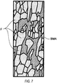
- a black part indicates a bainite phase, a martensite phase, or a residual austenite phase.
- crystal grains having the aspect ratio of 3 or more are present, the delayed fracture does not occur for reasons which will be described below.
- the predetermined range region A is set to calculate the amount of equivalent plastic strain in the sheared portion, it is possible to calculate the amount of equivalent plastic strain having a small error.
- the method of calculating the amount of equivalent plastic strain disclosed in the surface layer grain refining hot-shearing method according to the second embodiment is applicable to the calculation of the amount of equivalent plastic strain in the surface layer grain refining hot-shearing method according to the first embodiment.
- Example 7 Steel sheet Steel-sheet heating Rapidly cooling Amount of equivalent plastic strain Coefficient Shearing start temperature(°C) Presence or absence of cracks Dimensional error (%) Steel grade Ar3(°C) Temperature(°C) Time (min.)
- Example 7 A 420 950 1.5 Water 2.0 40 500 Absence 1.1
- Example 8 A 420 950 1.5 Die 2.0 60 560 Absence 1.1
- Example 9 B 480 950 1.5 Water 2.5 40 580 Absence 1.2
- Example 10 C 460 950 1.5 Water 1.8 40 532 Absence 1.1 Comparative Example 6 A 420 950 1.5 Water 2.0 10 440 Presence 0.7 Comparative Example 7 B 480 950 1.5 Water 2.5 10 475 Presence 0.8
Landscapes
- Chemical & Material Sciences (AREA)
- Engineering & Computer Science (AREA)
- Mechanical Engineering (AREA)
- Materials Engineering (AREA)
- Metallurgy (AREA)
- Organic Chemistry (AREA)
- Crystallography & Structural Chemistry (AREA)
- Thermal Sciences (AREA)
- Physics & Mathematics (AREA)
- Heat Treatment Of Articles (AREA)
- Heat Treatment Of Sheet Steel (AREA)
- Heat Treatment Of Steel (AREA)
- Mounting, Exchange, And Manufacturing Of Dies (AREA)
Description
- The present invention relates to a surface layer grain refining hot-shearing method of a steel sheet, which has a carbon content of 0.15% or more by mass and is used in automobiles, ships, bridges, construction equipment, various plants, or the like, and a workpiece obtained by surface layer grain refining hot-shearing.
- From the past, a metal material (steel sheet) to be used in automobiles, ships, bridges, construction equipment, various plants, or the like has been often subjected to shearing by a punch and a die. Recently, from the viewpoint of safety and weight lightening, various members become high strengthening, and as disclosed in "Press Technology", Vol. 46, No. 7, p. 36-41 (hereinafter, referred to as "Non-Patent
Literature 1"), a quenching press is performed in which press forming and heat treatment are almost simultaneously performed to form a high-strength member. - A general cold-pressed workpiece is subjected to shearing such as punching and trimming after being subjected to press forming. However, when the quenching-pressed workpiece is subjected to shearing after being subjected to forming, a service life of a shearing tool becomes significantly shorter due to high hardness of the member. In addition, there is a concern that delayed fracture occurs due to residual stress in a sheared portion. Thus, the quenching-pressed workpiece is often subjected to laser cutting rather than the shearing.
- However, since the laser cutting requires costs, for example, the following methods have been proposed so far: a method of performing a heat treatment after shearing (for example, see Japanese Patent Application Laid-Open (
JP-A) No. 2009-197253 Patent Literature 1 ")); methods of reducing residual stress in a sheared portion by simultaneously performing shearing and hot pressing before quenching (for example, seeJP-A No. 2005-138111 Patent Literature 2"),JP-A No. 2006-104526 Patent Literature 3"), andJP-A No. 2006-83419 Patent Literature 4")); a method of reducing quenching hardness by gradually lowering a cooling rate of a sheared portion (for example, seeJP-A No. 2003-328031 Patent Literature 5")); a method of working to soften only a shearing scheduled portion by performing local electric-heating (for example, see "CIRP Annals-Manufacturing Technology" 57 (2008), p. 321-324 (hereinafter, referred to as "Non-PatentLiterature 2")); and a shearing-related technology for controlling structures in a surface layer of a shear plane in a high-strength steel sheet to improve delayed fracture resistance (seeJP-ANo. 2012-237041 Patent Literature 6")). - There are several problems in the methods disclosed in
Patent Literatures 1 to 6 and the method disclosed inNon-Patent Literature 2. According to the method disclosed inPatent Literature 1, since the method can be used for only a specific material and is used to perform shearing on a quenched material, the problem such as deterioration in service life of the tool is not solved. - According to the methods disclosed in
Patent Literatures 2 to 4, the residual stress in the sheared portion caused by deformation resistance of the steel sheet can be reduced, but it is not possible to reduce thermal stress caused by seizure of the tool and non-uniformity of a contact with a die during quenching and to reduce residual stress caused by transformation of the steel sheet. Therefore, when ductility of the hot-sheared portion is low, the problem such as occurrence of the delayed fracture is not solved. A method of improving the ductility of the hot-sheared portion is not disclosed inPatent Literatures 2 to 4. - According to the method disclosed in
Patent Literature 5, it is considered that ductility can be improved because the sheared portion of the steel sheet is not hardened, but a shearing time becomes longer and thus costs increase as the cooling rate becomes slower. According to the method disclosed inNon-Patent Literature 2, it is necessary to prepare a new die formed with an electric heating apparatus for shearing and thus costs increase. - According to the method disclosed in
Patent Literature 6, it has an excellent effect of improving the delayed fracture resistance, but a shearing start temperature of from 400°C to 900°C is defined regardless of a material of a member to be sheared or a cooling rate. For this reason, the shearing may occur at a temperature range (low-temperature side), at which the delayed fracture occurs, depending on the materials of the member to be sheared or shearing conditions. Conversely, when the shearing is performed at a high temperature more than necessary such that the delayed fracture does not occur, the amount of thermal expansion becomes larger and a dimensional change becomes larger at the time of returning to an ambient temperature. As a result, the dimensional error of the workpiece becomes greater. Therefore, in a case in which the shearing temperature is precisely controlled at the lower temperature according to actual shearing conditions, there still remains a possibility of suppressing the delayed fracture while further improving shearing accuracy of the workpiece. -
Patent Literature 6 discloses that the delayed fracture does not occur when fine ferrite is present in the surface of a shearing portion. However, for example, in experimental numbers 36 to 40 in which a steel sheet A8 indicated in Table 5 obtained by steel sheet component A8 or A9 indicated in Table 1 of Example is used, even when the shearing is performed at the same shearing temperature and cooling rate under the same heating conditions and keeping conditions, structures vary and thus the delayed fracture may occur in some cases. Even when a steel sheet A9 indicated in Table 5 is used, the same results were obtained. - In order to solve the above problems, the invention has tasks to prevent delayed fracture occurring in a hot-sheared portion and to improve shearing accuracy of a workpiece without increasing the shearing time and new steps, and an object thereof is to provide a surface layer grain refining hot-shearing method and a workpiece obtained by surface layer grain refining hot-shearing, which meets these requirements, for the purpose of achieving of these tasks.
- The present inventors have intensively studied on a technique for solving the above problems. As a result, the inventors found that in a case in which a temperature for staring shearing (shearing start temperature) is set to an appropriate range based on the amount of equivalent plastic strain of a surface layer of a sheared portion, delayed fracture does not occur even when high residual stress remains in the sheared portion.
- That is, the amount of equivalent plastic strain of the sheared portion is affected by a temperature during the shearing and a structure before the shearing (ferrite or austenite), but a structure after the shearing is differently changed depending on the amount of equivalent plastic strain of the sheared portion and the shearing temperature. As to how the structure differs, compositions of the steel sheet, pressing conditions and temperature histories associated with these pressing conditions when pressing is performed before the shearing contribute thereto. The inventors found conditions in which even when high residual stress remains in the sheared portion, the dimension accuracy is improved without an occurrence of the delayed fracture by optimizing the shearing temperature in view of all these factors.
- In particular, the inventors confirmed, in a carbon steel for machine structural use defined in JIS G 4051 having a carbon content of 0.15% or more by mass or having preferably a carbon content of 0.48% or less by mass in view of cold workability after shear cooling, that the invention was applicable to cold-rolled steel sheets of S17C, S25C, S35C, and S45C defined in JIS G 4051 when an actually measured Ar3 point is approximately 500°C or lower at the time of cooling by leaving.
- The invention has been made based on the above findings and the gist thereof is as follows.
- A first aspect of the invention is to provide a surface layer grain refining hot-shearing method including: heating and keeping a steel sheet having a carbon content of 0.15% or more by mass in a temperature range of from Ac3 to 1400°C to austenitize the steel sheet; subsequently shearing the steel sheet in a state in which the steel sheet is placed on a die; and quenching by rapidly cooling the sheared steel sheet, wherein a start temperature of the shearing is set to be a temperature (°C) obtained by adding a temperature of from 30°C to 140°C to a previously measured Ar3 of the steel sheet.
- A second aspect of the invention is to provide a surface layer grain refining hot-shearing method including: heating and keeping a steel sheet having a carbon content of 0.15% or more by mass in a temperature range of from Ac3 to 1400°C to austenitize the steel sheet; subsequently shearing the steel sheet in a state in which the steel sheet is placed on a die; and quenching by rapidly cooling the sheared steel sheet, wherein a start temperature of the shearing is set to be a temperature (°C) obtained by adding a value, which is calculated by multiplying an amount of equivalent plastic strain of a surface layer in a sheared portion by a coefficient from 40 to 60, to a previously measured Ar3 of the steel sheet.
- A third aspect of the invention is to provide the surface layer grain refining hot-shearing method according to second aspect of the invention, wherein the amount of equivalent plastic strain of the surface layer in the sheared portion is calculated as an average value of an amount of equivalent plastic strain of a region in a range of from 5% to 20% of a thickness of the steel sheet from a shear plane of the sheared portion to an inside of the steel sheet in a normal direction of the shear plane and in a range of from 20% to 50% of the thickness of the steel sheet in a thickness direction of the steel sheet from a bottom on a burr side of the sheared portion.
- A fourth aspect of the invention is to provide the surface layer grain refining hot-shearing method according to the second or third aspect of the invention, wherein the amount of equivalent plastic strain of the surface layer in the sheared portion is calculated by a numerical simulation that is performed based on a stress-strain diagram at a steel sheet temperature of from 500°C to 800°C.
- A fifth aspect of the invention is to provide the surface layer grain refining hot-shearing method according to any one of the second aspect to the fourth aspect of the invention, wherein the amount of equivalent plastic strain of the surface layer in the sheared portion is calculated based on a Mises yield function represented by the following Formula (1).

- A sixth aspect of the invention is to provide the surface layer grain refining hot-shearing method according to the first or second aspect of the invention, wherein the shearing of the steel sheet starts within three seconds after the steel sheet comes in contact with the die.
- A seventh aspect of the invention is to provide the surface layer grain refining hot-shearing method according to the first or second aspect of the invention, wherein the rapid cooling is performed when the steel sheet comes in contact with the die.
- An eighth aspect of the invention is to provide the surface layer grain refining hot-shearing method according to the first or second aspect of the invention, wherein the rapid cooling is performed when water jetting from a puncture formed in a contacting portion of the steel sheet with the die passes through a groove provided in the contacting portion of the steel sheet.
- A ninth aspect of the invention is to provide the surface layer grain refining hot-shearing method according to the first or second aspect of the invention, wherein press forming not accompanying fracture of the steel sheet is performed between the heating and the shearing of the steel sheet.
- A tenth aspect of the invention is to provide a workpiece obtained by surface layer grain refining hot-shearing, including: a steel sheet having a carbon content of 0.15% or more by mass, a surface layer of a sheared portion of the steel sheet having a carbon content of 0.15% or more by mass including a ferrite phase and a remainder, the surface layer being defined as a range up to 100 µm inside of the steel sheet in a normal direction of a shear plane from a fracture plane of the sheared portion; wherein the remainder includes at least one phase of a bainite phase, a martensite phase, or a residual austenite phase which have a crystal grain diameter of 3 µm or less, and includes cementite and inevitably generated inclusions; wherein the ferrite phase has an average grain size of 3 µm or less; wherein the surface layer contains 5% or more grains by number having an aspect ratio of 3 or more; and wherein a region out of the range of 100 µm includes: martensite and inevitably generated inclusions; or bainite, martensite, and inevitably generated inclusions.
- An eleventh aspect of the invention is to provide the workpiece obtained by surface layer grain refining hot-shearing according to the tenth aspect of the invention, wherein, in the surface layer, the cementite has a number density of 0.8 pieces/µm3 or less and the cementite has a maximum length of 3 µm or less.
- A twelfth aspect of the invention is to provide the workpiece obtained by surface layer grain refining hot-shearing according to the tenth or eleventh aspect of the invention, wherein a total area ratio of the bainite phase, the martensite phase, and the residual austenite phase, which are measured by an electron-beam backscattering diffraction (EBSD) method, is from 10% to 50% in the surface layer.
- A thirteenth aspect of the invention is to provide a workpiece obtained by surface layer grain refining hot-shearing, the workpiece produced by: heating and keeping a steel sheet having a carbon content of 0.15% or more by mass in a temperature range of from Ac3 to 1400°C to austenitize the steel sheet; subsequently shearing the steel sheet in a state in which the steel sheet is placed on a die; and quenching by rapidly cooling the sheared steel sheet, wherein a start temperature of the shearing is set to be a temperature (°C) obtained by adding a temperature of from 30°C to 140°C to a previously measured Ar3 of the steel sheet.
- A fourteenth aspect of the invention is to provide a workpiece obtained by surface layer grain refining hot-shearing, the workpiece produced by: heating and keeping a steel sheet having a carbon content of 0.15% or more by mass in a temperature range of from Ac3 to 1400°C to austenitize the steel sheet; subsequently shearing the steel sheet in a state wherein the steel sheet is placed on a die; and quenching by rapidly cooling the sheared steel sheet, wherein a start temperature of the shearing is set to be a temperature (°C) obtained by adding a value, which is calculated by multiplying an amount of equivalent plastic strain of a surface layer in a sheared portion by a coefficient from 40 to 60, to a previously measured Ar3 of the steel sheet.
- According to a surface layer grain refining hot-shearing method and a workpiece obtained by surface layer grain refining hot-shearing of the invention, it is possible to suppress delayed fracture in a sheared portion and to provide a workpiece having excellent dimension accuracy without increasing the shearing time and new steps.
-
-
Fig. 1A is a schematic diagram illustrating an example of punching-shearing by a punch and a die. -
Fig. 1B is a schematic diagram illustrating an example of trimming-shearing by a punch and a die. -
Fig. 2 is a diagram illustrating an example of a sheared portion of a steel sheet. -
Fig. 3 is a diagram illustrating a relation between a temperature history and an Ar3 point. -
Fig. 4A is a diagram illustrating a state of a hot-shearing apparatus used in Test A before shearing. -
Fig. 4B is a diagram illustrating a state of the hot-shearing apparatus used in Test A during shearing. -
Fig. 4C is a diagram illustrating a state of the hot-shearing apparatus used in Test A after shearing. -
Fig. 5 is a diagram illustrating inclusions (a transmission electron microscope image observed by a replica method), which are observed by a replica method using a transmission electron microscope in Comparative Example, in a surface layer of a sheared portion. -
Fig. 6A is a diagram illustrating a region in which equivalent plastic strain is averaged. -
Fig. 6B is a diagram illustrating a region in which a fine structure in an actually hot-sheared portion is formed. -
Fig. 7 is an example of metal structure (EBSD image) obtained by Example 1. -
Fig. 8 is an example of inclusions (a transmission electron microscope image observed by a replica method) of a metal structure obtained by Example 1. -
Fig. 9A is a diagram illustrating a bending state of a hot-shearing apparatus used in Test B. -
Fig. 9B is a diagram illustrating a shearing state of a hot-shearing apparatus used in Test B. - A surface layer grain refining hot-shearing method and a workpiece obtained by surface layer grain refining hot-shearing according to a first embodiment of the invention will be described below.
- First, general shearing will be described and a sheared portion of the sheared workpiece which is subjected to the shearing will be then described.
- As illustrated in
Figs. 1A and1B , punching-shearing or trimming-shearing is performed on asteel sheet 1 placed on adie 3 by lowering of apunch 2. At this time, as illustrated inFig. 2 , a shearedportion 8 of thesteel sheet 1 is configured by (a) ashear drop 4 that is formed in such a manner that thesteel sheet 1 is totally pressed by thepunch 2, (b) ashear plane 5 that is formed in such a manner that thesteel sheet 1 is drawn into a clearance between thepunch 2 and the die 3 (a gap between thepunch 2 and the die 3) and is then locally stretched, (c) afracture plane 6 that is formed in such a manner that thesteel sheet 1 drawn into the clearance between thepunch 2 and thedie 3 is fractured, and (d) aburr 7 that is generated on the back surface of thesteel sheet 1. - In the following description of the embodiment, the same components are also denoted by the same reference numerals and the detailed description thereof will be not presented.
- In this embodiment, a term of "surface layer of the sheared portion" is used, and this refers to a region from the surface of the sheared portion up to 100 µm in a normal direction of the shear plane.
- Hereinafter, first, the findings of the inventors on the hot shearing are described, the surface layer grain refining hot-shearing method found based on the findings is then described, and the workpiece obtained by surface layer grain refining hot-shearing formed by such a shearing method is finally described together with the operation of the shearing method.
- In the hot shearing according to this embodiment, a steel sheet of high-carbon region of 0.15% or more by mass is used. A transformation start temperature (Ae3 point) in a state diagram from austenite to ferrite of the steel sheet is from 800°C to 900°C. A portion, which is subjected to large plastic deformation in the austenite state, is transformed to ferrite without an occurrence of martensite transformation even when being rapidly cooled. Therefore, when being rapidly cooled after being sheared at a temperature range of an austenite single phase based on the state diagram, almost entirely of the surface layer of the sheared portion having large plastic deformation is transformed into ferrite and other portions, which are not plastically deformed, are transformed into martensite. However, when the shearing temperature is high, dimension accuracy becomes poor due to thermal strain. In addition, there was a problem that variation in occurrence of delayed fracture results from the plastically-deformed ferrite at the time of the shearing at a temperature range in which the austenite and the ferrite are mixed based on the state diagram.
- Then, the inventors have experimented to perform the shearing on the steel sheet which is subjected to a soaking treatment followed by changing a temperature for starting the shearing (shearing start temperature). With respect to the shearing start temperature, a thermocouple was embedded at the center in a thickness direction of the sheet at a position spaced apart by 3 to 5 mm from a shearing position of the steel sheet to measure the temperature at the start of shearing. Since the steel sheet is heat-released and thus lowered in the temperature when coming in contact with a die, the shearing of the steel sheet started within three seconds after the steel sheet comes in contact with the die.
- In this embodiment, the "die" refers to the
die 3 and a pad 12 (seeFig. 4A ) to be used during the shearing. Furthermore, the meaning of "after the steel sheet comes in contact with the die" refers to the time after thesteel sheet 1 comes in contact with either of thedie 3 or thepad 12. - As a result, the inventors found that there is a temperature range in which the delayed fracture does not occur on the sheared portion (fracture plane) of the steel sheet and the dimension accuracy is improved and that this temperature range varies depending on shearing conditions or components of the steel sheet. The inventors also found that cooling control of the steel sheet before the shearing also affects the delayed fracture of the sheared portion (fracture plane) or the dimension accuracy of the workpiece.
- The inventors found that fine bainite or fine martensite and fine residual austenite are added in addition to fine ferrite and that cementite reduces when the shearing start temperature is set to be an appropriate temperature as will be described below.
- In general, the fine ferrite structure has toughness higher than the martensite structure. Therefore, when the fine ferrite structure having high toughness is present in the surface layer of the sheared portion, the delayed fracture is suppressed.
- The shearing start temperature having an appropriate temperature range was obtained by considering temperature changes in the hot shearing and further calculating the size of shearing strain.
- The steel sheet was first heated to 950°C and after keeping it for 90 seconds and then cooling it in a state being placed on four pointed needles (hereinafter, sometimes referred to as a "pin support"), the transformation temperature of the steel sheet was measured. The temperature was measured by the thermocouple embedded in the steel sheet.
- The measured Ar3 point is a temperature that starts to transform to a BBC crystalline structure such as ferrite from the austenite structure of an FCC crystal at a finite cooling rate rather than the assumption that the cooling rate is zero as in the state diagram.
- The measured Ar3 point was significantly different in the range of from 200 to 300°C from a transformation temperature (Ae3 point) at which austenite was changed to ferrite as illustrated in the state diagram. Further, the Ar3 point measured in a surface contact state with the die (quenching is inadequate, but the cooling rate is faster compared to the case of the pin support) was as low as about 400°C compared to the Ae3 point, that is, was as low as about 100°C compared to the case of the pin support.
- The fact that the Ar3 point is lower than the Ae3 point is common technical knowledge in the field of metallic materials. However, a quantitative difference between the Ar3 point and the Ae3 point is not clear. By testing of the inventors, it was clear that the significant difference between the Ar3 point and the Ae3 point is present in the hot shearing as described above.
- For reference, results of measurement of the Ar3 point by the above measuring method (pin support) are illustrated in
Fig. 3 . The steel sheet to be mainly used had a sheet thickness of 1.5 mm. The range of the thickness of the steel sheet to be used in the shearing is of about from 0.5 mm to 3.0 mm. Since the Ar3 point is the transformation start temperature at which the austenite is changed to the ferrite, it is not necessary to include shearing and a quenching (rapid cooling) process on the measurement of the Ar3 point. Accordingly, the quenching process is not included in the graph ofFig. 3 . - In
Fig. 3 , initially, the cooling rate was 7°C/s, and the cooling rate has sharply declined when the time has elapsed for 50 seconds from a cooling start. A temperature (about 680°C) of the steel sheet at which the cooling rate of the steel sheet is equal to or less than 1°C/s is identified as the transformation temperature (Ar3 point). At the time of the measurement of the Ar3 point, the steel sheet is cooled to room temperature as it is, but, in actual fact, the shearing starts at a temperature higher than the Ar3 point and the quenching process is then performed. - In this embodiment, an Ar3 temperature measured using the same method as in the case of the above pin support under placing conditions of a sheet to be actually sheared is defined as the "measured Ar3 (of the steel sheet)". The cooling rate is generally about from 5°C/s to 30°C/s (state of cooling by leaving) at the time of the measurement in many cases.
- As long as appropriate hot-shearing conditions are ascertained by performing the above experiment as a preliminary test, when performing appropriate soaking temperature management of the steel sheet and time management up to the shearing start after placing the steel sheet in the die at steps of an actual mass production process, it is not necessary to perform the operation after preparing the die in which the thermocouple is embedded and measuring a surface temperature of the steel sheet to be sheared at the time of the shearing start for every shearing. In the case of performing the operation by measuring the surface temperature of the steel sheet in the mass production process, the surface temperature of the steel sheet may be measured immediately before the hot-shearing using a radiation thermometer.
- From the fact that the plastic deformation caused by the shearing is related to the structure of the sheared portion as described above, the inventors derived plastic strain in the vicinity of the sheared portion by numerical calculation. Here, the plastic strain was evaluated as equivalent plastic strain.
- From the fact that the actual shearing is performed at a range higher than the measured Ar3 temperature, as a premise of the calculation, the numerical value of mechanical characteristics such as deformation resistance of the steel sheet was defined as a value of austenite. In addition, the temperature dependence of the mechanical characteristics of austenite was obtained using an actual measurement value in a hot tensile test (after heating the steel sheet to a temperature higher than or equal to the Ac3 point, the steel sheet is cooled by leaving to a predetermined temperature, and then a tensile test is performed) of 22MnB5 equivalent steel which is widely used for hot stamping. Such a temperature dependence is disclosed in, for example, "Hongsheng Liu, Jun Bao, Zhongwen Xing, Dejin Zhang, Baoyu Song, and Chengxi Lei; "Modeling and FE Simulation of Quenchable High Strength Steels Sheet Metal Hot Forming Process", Journal of Materials Engineering and Performance, Vol. 20(6), 2011, pp.894 to pp. 902" (hereinafter, sometimes referred to as "
Non-Patent Literature 3"), and practitioners may use values disclosed in this Literature without actually measuring the values. - The plastic strain obtained by the numerical calculation is largest at the surface of the shearing surface, and becomes smaller moving away from the surface. Furthermore, it was found that an occurrence region of the equivalent plastic strain of 100% or more at the sheared portion coincides with an actual occurrence region of the fine structure in a predetermined temperature range.
- With respect to the values obtained by the numerical calculation, it is concerned that variation is caused by analysts. Therefore, the inventors performed the numerical calculation using steel grades, analyst, and software in plural ways. As a result of the numerical calculation, the inventors obtained the result that the temperature range at which the occurrence region (distance) of the equivalent plastic strain of 100% or more in the normal direction of the shear plane at the sheared portion coincides with the occurrence region of the fine structure in the normal direction of the shear plane is a temperature range higher by approximately 30 to 140°C than the measured Ar3.
- Here, at a temperature range higher than a temperature obtained by adding 140°C to the measured Ar3 (hereinafter, sometimes referred to as "higher than Ar3 + 140°C"), the occurrence region of the equivalent plastic strain of about 100% in the normal direction of the shear plane on the sheared portion which is obtained by calculation becomes larger than the actual fine region on the sheared portion of the workpiece. As a result of analysis of the fine structure region, the region was mainly configured by ferrite and carbide. On the other hand, other regions except the surface layer are configured by a martensite structure.
- The ferrite and the martensite have a different volume, respectively, from the difference of a crystal structure and a solid-solution state of element. Therefore, when the fine structure region is widely formed on the surface layer of the sheared portion and most of the fine structure is configured by ferrite, the boundary area between the fine ferrite and the fine martensite increases. As a result, the dimension accuracy of the workpiece deteriorates. In consideration of the thermal strain, the dimension accuracy of the workpiece deteriorates as the shearing start temperature becomes higher.
- Furthermore, when the shearing start temperature is lower than a temperature obtained by adding 30°C to the measured Ar3 (hereinafter, sometimes referred to as "lower than Ar3 + 30°C"), the actual fine region is smaller than the occurrence region of the equivalent plastic strain of 100% or more. Since the occurrence region of the equivalent plastic strain of 100% or more becomes smaller, the actual fine structure region smaller than such a region becomes further smaller. At the temperature lower than "Ar3 + 30°C" which is measured, a part of austenite starts to transform into ferrite by the influence of internal heat distribution, and such ferrite is plastically deformed by the shearing. Consequently, the inventors found that residual stress is excessively large on the surface of the sheared portion of the workpiece and thus the risk of the delayed fracture increases.
- On the other hand, when the shearing start temperature is higher than "Ar3 + 30°C", the steel sheet is subjected to the shearing before austenite starts to transform into ferrite, so excessive residual stress on the sheared portion due to ferrite is avoided.
- Based on the above findings, the surface layer grain refining hot-shearing method according to this embodiment was configured as follows.
- First, a shearing machine used in the test will be briefly described. As illustrated in
Fig. 4A , a shearingmachine 10 includes thedie 3 on which thesteel sheet 1 is placed, apad 12 that is disposed on thedie 3 to press thesteel sheet 1 placed on thedie 3, and apunch 2 that is disposed inside thepad 12 and is inserted into apuncture 14 of thedie 3 to punch a predetermined range of thesteel sheet 1. - First, the
steel sheet 1 having the carbon content of 0.15% or more by mass is placed on thedie 3 after being heated to the range of from Ac3 to 1400°C higher than the shearing start temperature in the range of from Ar3 + 30°C to Ar3 + 140°C and being subjected to a soaking treatment (seeFig. 4A ). - Then, as illustrated in
Fig. 4B , after thesteel sheet 1 on thedie 3 is pressed by thepad 12, thesteel sheet 1 is subjected to the shearing by thepunch 2. After thesteel sheet 1 is placed on thedie 3, the shearing of thesteel sheet 1 starts within three seconds. By control of the time (shearing start time) until the shearing starts after thesteel sheet 1 is placed on thedie 3, the temperature of thesteel sheet 1 during the shearing is controlled in the range of from Ar3 + 30°C to Ar3 + 140°C. - As illustrated in
Fig. 4C , a predetermined range of thesteel sheet 1 is punched by thepunch 2, the punchedsteel sheet 1 is rapidly cooled and quenched by thedie 3 and thepad 12, and thus a shearing-workpiece is formed. - Operation of the surface layer grain refining hot-shearing method according to this embodiment as described above and the workpiece obtained by surface layer grain refining hot-shearing (hereinafter, sometimes referred to as a "workpiece") formed by this shearing method will be described.
- In the sheared
portion 8 of the workpiece (steel sheet) formed in this manner, the surface layer of the shearedportion 8 defined as the range up to 100 µm inside of the steel sheet in a normal direction of theshear plane 5 includes a ferrite phase forming at least a portion of the fracture plane and the remainder, and the remainder has a bainite phase, a martensite phase, a residual austenite phase, and cementite and inevitably generated inclusions. The ferrite phase, the bainite phase, the martensite phase, and the residual austenite phase which are formed in the surface layer of the shearedportion 8 have an average grain size of 3 µm or less, respectively. The surface layer of the shearedportion 8 contains 5% or more grains by number having an aspect ratio of 3 or more. In addition, other regions except the surface layer of the shearedportion 8 includes a mixed structure of an inevitably generated inclusion and martensite or a mixed structure of martensite, bainite, and an inevitably generated inclusion. - That is, since the workpiece is formed by the shearing of the
steel sheet 1 heated to the temperature of from Ar3 point + 30°C to Ar3 point + 140°C, a fine ferrite structure, a fine martensite structure, a fine bainite structure, and a fine residual austenite structure are formed in the surface layer of the sheared portion 8 (fracture plane 6) (seeFig. 2 ).Fig. 6B illustrates thesteel sheet 1 which has actually been subjected to the shearing. As illustrated inFig. 6B , afine structure 11 is formed from thefracture plane 6 toward theshear plane 5 in the shearedportion 8 in the surface layer, but the fine structure is formed particularly up to a depth of about 100 µm from the surface in thefracture plane 6. - The fine ferrite structure has generally higher toughness than the martensite structure. Accordingly, since the fine ferrite structure of the high toughness is present in the surface layer of the sheared portion 8 (fracture plane 6), occurrence of the delayed fracture in the sheared portion 8 (fracture plane 6) due to the delayed fracture is suppressed.
- As will be described below, in the workpiece according to this embodiment, the occurrence of the delayed fracture in the sheared portion 8 (fracture plane 6) can be suppressed by the fine martensite structure, the fine bainite structure, and the fine residual austenite structure which are formed in the surface layer of the sheared portion 8 (fracture plane 6).
- For reference,
Fig. 7 illustrates a structure photograph of the surface layer of the sheared portion obtained by an EBSD of this embodiment. - In
Fig. 7 , a black part indicates a bainite phase, a martensite phase, or a residual austenite phase. As in the photograph, although crystal grains having the aspect ratio of 3 or more are present, the delayed fracture does not occur for reasons which will be described below. - The "grain size" used herein means a circle diameter, that is, a circle conversion diameter (circle equivalent diameter) when an area of each ferrite crystal grain, which is observed in a cross section along the thickness direction of the steel sheet in the normal direction of the shear plane, is replaced by a circle of the same area.
- The bainite phase, the martensite phase, or the residual austenite phase rather than the single phase of the fine ferrite phase is present in the surface layer of the sheared
portion 8. Generally, the bainite phase, the martensite phase, or the residual austenite phase present in the ferrite phase traps diffusible hydrogen that causes the delayed fracture. Therefore, when these phases are present in the fine ferrite phase, it is possible to obtain an effect of suppressing the delayed fracture. - In addition, when the bainite phase, the martensite phase, or the residual austenite phase becomes finer to be 3 µm or less, sites for trapping the diffusible hydrogen further increase, and thus the delayed fracture is further suppressed.
- On the other hand, the cementite has a small effect of trapping the diffusible hydrogen and can be a start point of the occurrence of the delayed fracture, so it is preferable that the cementite becomes smaller.
- In order for the remainder to have the fine bainite phase, martensite phase, and/or residual austenite phase having the grain size of 3 µm or less, ferrite having an aspect ratio of more than 3 inevitably appeared. As a result of analysis using a transmission electron microscope, the ferrite having the aspect ratio of more than 3 is in a state where plastic deformation little occurs or is small, but is not in a state of being plastically deformed and stretched as described in
Patent Literature 6, so the ferrite did not adversely affect resistance to the delayed fracture. While the details of the operation is not clear, in order for the remainder to have the bainite phase, the martensite phase, or the residual austenite phase described above, the ferrite structure having the aspect ratio of more than 3 is essentially present. - In order to also make these structures, it is necessary to adjust the shearing temperature to a temperature range of from Ar3 + 30°C to Ar3 + 140°C. It is considered that since the steel sheet is cooled at a certain cooling rate, the austenite structure remains at the shearing temperature, but the appropriate amount of shearing strain is added and transformation nuclei to transform into other phases other than the martensite is already generated. In this case, the cooling rate contributes to any phase transformation.
- The cooling rate is fast when the temperature exceeds Ar3 + 140°C, and the austenite becomes a supercooled state during cooling (temperature is lower than a temperature range at which structure morphology can be present) when the shearing strain is applied to the extent in which transformation to martensite cannot occur. In such a case, austenite is easily transformed into a fine ferrite structure.
- On the other hand, when the temperature is equal to or lower than Ar3 + 140°C, grains are formed in which transformation to ferrite does not occur and transformation to martensite also does not occur under the influence of shearing strain. Such grains become a bainite phase. In addition, grains are also present in which shearing strain is small and transformation to martensite occurs. Additionally, the transformation to the non-uniform three phases partially induces enrichment of carbon to austenite, and such austenite becomes residual austenite in order to be stable even at room temperature. Since these phases occur between the fine ferrite grains, the phases themselves also become finer to be 3 µm or less.
- In order to stably form these structures, the shearing of the steel sheet preferably starts within three seconds after the steel sheet comes in contact with the die. When the shearing starts after three seconds, scale occurs on the surface of the steel sheet and the contact of the die with the steel sheet becomes non-uniform. When heat irregularity occurs due to the non-uniform contact, variation in cooling condition of the sheared portion is caused.
- In addition,
Fig. 5 illustrates cementite distribution in the surface layer of the fracture plane when the steel sheet disclosed inPatent Literature 6 is subjected to the shearing at a temperature higher than Ar3 point + 140°C. InPatent Literature 6, since the shearing start temperature is simply set to only a temperature range of from 400°C to 900°C, the shearing start temperature also includes the case of being higher than Ar3 + 140°C. In this case, for example, as illustrated inFig. 5 , cementite C (black parts excluding circles) has a number density of 0.8 pieces/µm3 or more and the maximum length of 3 µm or more. - On the other hand, in the case of this embodiment, cementite (black parts excluding circles) in the surface layer of the fracture plane of the steel sheet has a number density of 0.8 pieces/µm3 or less and the maximum length of 3 µm or less as indicated in test results (
Fig. 8 ) to be described below. According to the experience of the inventors, when the number of cementite is small to this extent and the size of cementite is also small, the cementite itself does not almost cause a problem of being a start point of the occurrence of the delayed fracture. - As illustrated in
Fig. 7 , a total area ratio of the bainite phase, the martensite phase, or the residual austenite phase, which is measured by observation in the range up to 100 µm inside of the steel sheet in the normal direction of the shear plane from the fracture plane in the sheared portion of the steel sheet using an electron-beam backscattering diffraction (EBSD) method, is from 10% to 50%. - As for this, according to the experience of the inventors, when the total area ratio of these phases is less than 10%, it is not possible to sufficiently perform the storage of the diffusible hydrogen and the risk of the delayed fracture increases. On the other hand, when the total area ratio of these phases exceeds 50%, the ratio of the fine ferrite in the surface layer of the fracture plane reduces, whereby the effect of toughness improvement due to the fine ferrite decreases and the risk of the delayed fracture increases. Although the effect of the invention does not immediately disappear when the total area ratio of these phases is out of such a range, the total area ratio of these phases is more preferably within such a range.
- A method of rapidly cooling the
steel sheet 1 after the shearing is not limited to rapid cooling by the contact of the die (die 3 and pad 12) with thesteel sheet 1 as in this embodiment and, for example, thesteel sheet 1 may be rapidly cooled by allowing thesteel sheet 1 to come in directly contact with water. Examples of the method of allowing thesteel sheet 1 to come in contact with water may include a method of passing cooling water through a groove formed in a contacting portion of the steel sheet with the die. - Even in the case of performing the shearing after press forming, as in the workpiece of this embodiment, it is possible to suppress the delayed fracture of the sheared portion to form a workpiece with dimension accuracy.
- A surface layer grain refining hot-shearing method according to a second embodiment of the invention will be described. The same components as in the first embodiment are denoted by the same reference numerals, and the detailed description thereof will not be presented. In addition, a workpiece obtained by surface layer grain refining shearing formed by the surface layer grain refining hot-shearing method according to this embodiment is the same as in the first embodiment, so operational effects thereof will not be described.
- The inventors found that the temperature range at which the occurrence region of about 100% equivalent plastic strain in the normal direction of the shear plane in the sheared portion coincides with the occurrence region (distance) of the fine ferrite structure, the fine martensite structure, the fine bainite structure, or the fine residual austenite structure in the normal direction of the shear plane is obtained when a temperature (°C) obtained by adding a value, which is calculated by multiplying the amount of equivalent plastic strain of the surface layer in the sheared portion by a coefficient from 40 to 60, to the measured Ar3 is set as a shearing start temperature.
- In this embodiment, it was considered that the following value was appropriate to use as the amount of equivalent plastic strain of the surface layer in the sheared portion.
- As illustrated in
Fig. 6A , an average value of the amounts of plastic strain obtained by calculation at a region A (within a thick line frame) in the range of from 5 to 20% of a thickness H of thesteel sheet 1 from theshear plane 5 of the shearedportion 8 to the inside of thesteel sheet 1 in the normal direction of theshear plane 5 and in the range of from 20% to 50% of the thickness H of thesteel sheet 1 in the thickness direction of thesteel sheet 1 from a bottom 12 on theburr 7 side of the shearedportion 8 was used as the amount of equivalent plastic strain of the surface layer in the sheared portion. - By setting the region A in this way, the inventors found that the amount of equivalent plastic strain having a small influence by differences in analyst or analysis condition was obtained. This value is considered to be a reasonable numerical value as the amount of equivalent plastic strain as will be described below, but other values of correction strain may be used according to a calculation unit.
- The amount of equivalent plastic strain of the surface layer in the sheared portion used a value obtained by the calculation at a temperature range of from 500°C to 800°C. It was confirmed that the amount of equivalent plastic strain of the surface layer becomes approximately constant at this range.
the reason that a lower limit of 40 is set for the coefficient to be multiplied by the amount of equivalent plastic strain is due to consideration of differences in the coefficient due to a steel grade and errors in numerical calculation. By repetitive experiment and numerical calculation, the fine ferrite structure, the fine martensite structure, the fine bainite structure, or the fine residual austenite structure appeared even in the case of being out of this coefficient range, but the inventors obtained 40 as the lower limit of the coefficient in which appearance probability becomes higher. - In addition, the reason why the upper limit of the coefficient to be multiplied by the amount of equivalent plastic strain is set to 60 is that the dimension accuracy of the workpiece deteriorates when the shearing temperature is too high. This reason is considered that the region of the fine structure in the surface layer becomes wider as the temperature becomes higher, but the dimension accuracy deteriorates after cooling because a difference in density between the surface layer and another region adjacent to the surface layer is large and the thermal strain also increases.
- In a case in which the difference between a workpiece dimension and a design dimension of the workpiece generally falls within the range of -0% +5% of the design dimension, the defective rate of product is lowered to the extent of being economically acceptable and thus problems substantially disappear. Thus, as a result of trial and error, such an upper limit was determined.
- The measured Ar3 point of the steel sheet should be previously measured by a temperature drop history at the thermocouple or the like in a state in which the steel sheet is placed on the die to be actually used. The thermocouple is embedded in the die, and it is preferable to cause a thermocouple sensor to come in directly contact with the steel sheet which is a member to be sheared. This reason is that the measured Ar3 point varies depending on the cooling rate of the steel sheet. As illustrated in
Fig. 3 , it is widely known that the measured Ar3 point is measured as a point at which a temperature lowering rate varies. This technique is also used in Tests A and B to be described below. - In this embodiment, it is important to calculate the equivalent plastic strain of the sheared portion. In the hot-shearing, the metal-structure transformation inevitably occurs during or immediately after the shearing, and thus it is not possible to measure the equivalent plastic strain. Therefore, a shearing simulation is performed by analysis using a finite element method (FEM), and thus the equivalent plastic strain is calculated.
- In the shearing simulation, the plastic strain is steeply changed. For this reason, calculation results of the plastic strain of the surface layer in the sheared portion are likely to differ depending on analysts or analysis conditions. In order to reduce the influence of these analysts or analysis conditions, it is preferable to set a constant FEM analysis region and to average and calculate the equivalent plastic strain within the region.
- The inventors have set the region as a result of trial and error.
Fig. 6A illustrates the region in which the equivalent plastic strain is averaged. As illustrated inFig. 6A , the region A (within the thick line frame), in which the equivalent plastic strain is averaged, was set in the range of from 5 to 20% of the thickness H (seeFig. 4 ) of thesteel sheet 1 from theshear plane 5 of the shearedportion 8 to the inside of thesteel sheet 1 in the normal direction of theshear plane 5 and in the range of from 20% to 50% of the thickness H of thesteel sheet 1 in the thickness direction of thesteel sheet 1 from the bottom 12 on theburr 7 side of the sheared portion. - During the simulation, since the temperature change sequentially occurs, it is necessary to perform repetitive calculation in such a manner that: a tentative shearing start temperature is set; the equivalent plastic strain is calculated based on the tentative shearing start temperature; and a true shearing start temperature is determined based on the calculated equivalent plastic strain. Such calculation requires costs.
- As a result of the calculation with several levels by the inventors, it was found that approximation can be performed when a numerical simulation is once performed based on stress-strain diagram at any of the steel sheet temperature of from 500°C to 800°C.
- As a premise of the calculation, when the shearing is performed at the range higher than the measured Ar3 temperature, numerical values of mechanical characteristics such as rigidity of the steel sheet at that time were defined as values of austenite.
- During the simulation, the shearing start temperature can be calculated without any problem when the equivalent plastic strain is calculated by a Mises yield function on the supposition of an isotropy without considering an anisotropy in particular.
- An increment in equivalent plastic strain "dε-P" by the Mises yield function is represented by the following formula when a material coordinate system is defined as x, y, and z, and the equivalent plastic strain is given as an integral of this increment.

- As described above, in the shearing method according to this embodiment, the structures such as the fine ferrite are formed in the surface layer in the sheared portion and the occurrence of the delayed fracture in the sheared portion (fracture plane) is suppressed when the steel sheet is subjected to the shearing at the calculated shearing start temperature, and it is possible to suppress the thermal strain or the like and ensure the dimension accuracy of the workpiece by allowing the shearing start temperature to be within the predetermined range.
- In particular, since the predetermined range region A is set to calculate the amount of equivalent plastic strain in the sheared portion, it is possible to calculate the amount of equivalent plastic strain having a small error.
- During the FEM simulation for calculating the equivalent plastic strain, since the temperature change sequentially occurs, it was necessary to perform repetitive calculation in such a manner that: the equivalent plastic strain was calculated based on the tentative shearing start temperature; and the true shearing start temperature was determined based on the calculated equivalent plastic strain. In this embodiment, however, since the approximation can be performed when a numerical simulation is only once performed based on stress-strain diagram at any of the steel sheet temperature of from 500°C to 800°C, the calculation is simplified.
- Since the equivalent plastic strain is calculated by the Mises yield function on the supposition of an isotropy, the calculation is further simplified.
- The method of calculating the amount of equivalent plastic strain disclosed in the surface layer grain refining hot-shearing method according to the second embodiment is applicable to the calculation of the amount of equivalent plastic strain in the surface layer grain refining hot-shearing method according to the first embodiment.
- Next, Examples of the invention will be described. However, shearing conditions in Examples are examples adopted to confirm feasibility and an effect of the invention and the invention is not limited to these shearing conditions. The invention can adopt various shearing conditions as long as the object of the invention is achieved within a range of not departing from the gist of the invention.
- Using the shearing
machine 10 illustrated inFigs. 4A to 4C , after the high-strength steel sheet 1 (200 mm × 150 mm) of steel grades A to C having compositions indicated in Table 1 is placed on thedie 3, thepunch 2 together with thepad 12 approach the top of thesteel sheet 1 from the above. Thesteel sheet 1 is pressed by thepad 12 and thesteel sheet 1 is subjected to the shearing by the punch 2 (width of 65 mm) at the same time. The shearedsteel sheet 1 is rapidly cooled by the die (die 3 and pad 12). Shearing conditions are as indicated in Table 2. A clearance between thepunch 2 and thedie 3 was set to be 0.15 mm. - Except for Comparative Examples, the keeping time until the shearing of the
steel sheet 1 starts after coming in contact with thedie 3 was set to be from 0.5 seconds to 3 seconds. The shearing start temperatures in Table 2 are temperatures obtained within the range of the keeping time. - The thickness of the steel sheets used in Examples was set to be 1.5 mm. The thickness of the steel sheet applicable to the invention has the range of from about 0.5 mm to 3 mm.
- The measured Ar3 point of each steel sheet was obtained by the measurement of the temperature history at the time when the steel sheet heated to 950°C is cooled in contact with the top of the die on the shearing machine (a temperature at which the cooling rate of the steel sheet was 1°C/sec. or less before the temperature of the steel sheet was lowered to the room temperature was regarded as the Ar3 point).
- For estimation of the equivalent plastic strain, shearing simulation, in which deformation resistance was input when the steel sheet is 750°C, was performed by a finite element method using Abaqus/Standard made by Dassault Systemes Co, which is commercial software. In this case, the Mises yield function was used, and the analysis region in the vicinity of a tool cutting edge was defined as a quadrilateral complete integration element of 0.02 mm × 0.04 mm. In addition, remeshing was performed every 0.05 mm punching press. The fracture was defined by a ductile fracture model of Hancock & Mackenzie, and the rigidity of elements satisfying conditions was zero. Parameters of the ductile fracture model were fitted based on a shear plane ratio which was actually observed in certain conditions. The equivalent plastic strain was used which was averaged in the region A set in the range of 10% of the thickness H of the
steel sheet 1 from theshear plane 5 of the shearedportion 8 in the normal direction of theshear plane 5 and in the range of 30% of the thickness H of thesteel sheet 1 in the thickness direction of thesteel sheet 1 from the bottom 12 on theburr 7 side of the sheared portion 8 (seeFig. 6A ). - A length of a scrap 16 (see
Fig. 4C ) punched out after the shearing was evaluated as the dimension accuracy. Unless a dimensional error occurs, the length of thescrap 16 after the shearing should be 65 mm. Thus, values are obtained in such a manner that the error in length of thescrap 16 after the shearing is divided by 65 and is then converted into percentage (× 100) are disclosed as the dimensional error in Table 2.[Table 1] (% by mass) Steel grade C Si Mn B Cr A 0.22 0.22 1.20 0.002 0.16 B 0.16 0.40 1.00 0.001 0.23 C 0.25 0.21 1.24 0.002 0.34 [Table 2] Steel sheet Steel-sheet heating Rapidly cooling Amount of equivalent plastic strain Coefficient Shearing start temperature(°C) Presence or absence of cracks Dimensional error (%) Steel grade Ar3(°C) Temperature(°C) Time (min.) Example 1 A 580 950 1.5 Water 2.0 50 680 Absence 2.0 Example 2 A 580 950 1.5 Die 2.0 60 700 Absence 4.2 Example 3 A 580 1000 1.0 Die 2.0 50 680 Absence 1.1 Example 4 B 620 950 1.5 Water 2.5 50 745 Absence 3.0 Example 5 B 620 950 1.5 Water 2.5 40 720 Absence 2.7 Example 6 C 570 950 1.5 Water 1.8 50 660 Absence 2.3 Comparative Example 1 A 580 950 1.5 Water 2.0 10 600 Presence 1.8 Comparative Example 2 B 620 950 1.5 Water 2.5 -10 595 Presence 1.8 Comparative Example 3 A 580 950 1.5 Water 2.0 85 750 Absence 5.1 Comparative Example 4 B 620 950 1.5 Water 2.5 80 820 Absence 6.3 Comparative Example 5 C 570 950 1.5 Water 1.5 100 720 Absence 5.1 - The test was performed three times for each Examples and Comparative Examples. With respect to the presence or absence of the delayed fracture, it was evaluated that the delayed fracture was present when delayed fracture occurs even once. In addition, the dimensional error was an average value of three measured values.
- In Examples 1 to 6, it can be understood that the occurrence of the delayed fracture in the sheared portion (fracture plane) is suppressed and the dimension accuracy of the workpiece is improved.
- A microstructure in the range of 100 µm from the fracture plane of the sheared portion in Example 1 will be described with reference to
Fig. 7 (EBSD, microstructure image) andFig. 8 (image of an extraction replica sample observed by the transmission electron microscope). - As illustrated in
Fig. 7 , it was confirmed that the microstructure includes ferrite, bainite, martensite, residual austenite, cementite, and inclusions derived from alloy elements other than iron as a result the EBSD analysis, EDS (characteristic energy dispersion type X-ray analysis), and electron diffraction analysis of the transmission electron microscope. - Specifically,
Fig. 7 illustrates the microstructure image observed by the EBSD in a state where a cross-section sample of Example 1 along the thickness direction of the steel sheet in the normal direction of the shear plane in the sheared portion is embedded in a hard resin and is then subjected to polishing and electropolishing. In addition,Fig. 8 illustrates the image observed by the transmission electron microscope of the sample of Example 1 which is prepared by an extraction replica method using an SPEED method (Potentiostatic Etching by Electrolytic Dissolution: potentiostatic electrolysis method in nonaqueous solvent). - As illustrated in
Fig. 7 (EBSD microstructure image), in the surface layer of the fracture plane in the range of 100 µm in the normal direction of the shear plane from the fracture plane, the grain size of ferrite (parts excluding black inFig. 7 ) F was as very small as 3 µm or less and the grain size of BMA (black part inFig. 7 ) including martensite, bainite, or residual austenite was also 3 µm or less. The crystal grain having the aspect ratio exceeding 3 was also seen in this range and the ratio was about 6% by number. - The same microstructure was observed in any of Examples 2 to 6. During the identification of the microstructure, five points of field-of-view of 8.0 × 20 µm were randomly photographed for each Example, in the range of 100 µm from the surface of the fracture plane.
- Furthermore, as illustrated in
Fig. 8 , it can be seen that the ratio of cementite (black parts excluding circles) C in Example 1 is very small. In Example 1, the number density of the cementite was 0.8 pieces/µm3, and the maximum length of the observed cementite was 3 µm or less. In order to determine a state of cementite distribution, five points of field-of-view of 9.5 × 7.5 µm from the surface layer of the sheared portion were randomly photographed for each condition. This was the same in any of Examples 2 to 6. - In Comparative Examples 1 to 5, on the other hand, a mixed structure (Comparative Examples 1 and 2) of bainite and martensite not including ferrite or a single phase of ferrite (Comparative Examples 3 to 5) was observed. In Comparative Examples 1 and 2, cementite and inclusion was hardly observed in almost same manner as illustrated in
Fig. 8 . In Comparative Examples 3 to 5, however, the cementite (seeFig. 5 , black part excluding circles) C having very high number density greatly exceeding 0.8 pieces/µm3 as illustrated inFig. 5 was observed. - An experiment was performed in a state where other conditions except for the shearing start temperature were the same as in Example 1, and the keeping time until the shearing of the steel sheet starts after being cooled in contact with the
die 3 and the pad 12 (also referred to as a die) was set to be 3.5 seconds. In this case, the shearing start temperature was also (Ar3 + 30°C) or higher, the delayed fracture occurred once in three repetitive experiments. As a result of observation the surface of the shearing surface of the resulting workpiece, in the range of 100 (µm from the shear plane, the structure of the surface layer of the sheared portion in the workpiece without an occurrence of the delayed fracture was configured to include: ferrite of which the grain size was as very small as 3 µm or less; and martensite, bainite, or residual austenite of which the grain size was also 3 µm or less. The crystal grain having the aspect ratio exceeding 3 was also seen and the ratio was about 7% by number. - In the range of 100 µm from the shear plane, however, the structure of the surface layer of the sheared portion in the workpiece with occurrence of the delayed fracture was configured to include: ferrite of which the grain size was about 5 µm; and martensite, bainite, or residual austenite of which the grain size was also 5 µm. In the surface layer of the sheared portion, the crystal grain having the aspect ratio exceeding 3 was also seen and the ratio was about 7% by number.
- A shearing
machine 20 includes: adie 3 which is formed with ahole 22 for bending and forming and apuncture 24 for punching deformation on the bottom of thehole 22 and in which thesteel sheet 1 is placed; apunch 2 which is inserted into thehole 22 to cause bending deformation of thesteel sheet 1; and amovable die 26 which is incorporated into thepunch 2 and is inserted into thepuncture 24 after the bending deformation to form a puncture (shearing) in a predetermined range of thesteel sheet 1. - By simulating press forming not accompanying fracture of the steel sheet, the shearing
machine 20 formed theheated steel sheet 1 in a hat shape by initially driving thepunch 2 after thesteel sheet 1 was placed on the die 3 (seeFig. 9A ). Thereafter, a test of punching thesteel sheet 1 using a movable die 13 to have a diameter of 20 mm was performed (seeFig. 9B ). - Except for Comparative Examples, the time until the shearing of the
steel sheet 1 starts after coming in contact with themovable die 26 was from about 0.1 seconds to about 0.5 seconds. - A clearance between the
punch 2 and thedie 3 was set to be 0.15 mm and the measured Ar3 was identified from a thermal history after the hat forming. The equivalent plastic strain was calculated in the same way as in Test A. Shearing conditions indicated in Table 3 were adopted. - An evaluation method in Test B is also the same as that in Test A.
- By the way, the dimension accuracy in Test B was evaluated by a diameter of a punch hole after the shearing. When the dimensional error does not occur, the diameter of the punch hole of the
steel sheet 1 after the shearing should be 20 mm. Thus, values are obtained in such a manner that the error in diameter of the punch hole after the shearing is divided by 20 and is then converted into percentage (× 100) and the values are disclosed as the dimensional error in Table 3 which indicates an implementation result of this test.[Table 3] Steel sheet Steel-sheet heating Rapidly cooling Amount of equivalent plastic strain Coefficient Shearing start temperature(°C) Presence or absence of cracks Dimensional error (%) Steel grade Ar3(°C) Temperature(°C) Time (min.) Example 7 A 420 950 1.5 Water 2.0 40 500 Absence 1.1 Example 8 A 420 950 1.5 Die 2.0 60 560 Absence 1.1 Example 9 B 480 950 1.5 Water 2.5 40 580 Absence 1.2 Example 10 C 460 950 1.5 Water 1.8 40 532 Absence 1.1 Comparative Example 6 A 420 950 1.5 Water 2.0 10 440 Presence 0.7 Comparative Example 7 B 480 950 1.5 Water 2.5 10 475 Presence 0.8 Comparative Example 8 C 460 950 1.5 Water 1.8 10 478 Presence 0.5 Comparative Example 9 A 420 950 1.5 Water 2.0 90 600 Absence 2.3 Comparative Example 10 B 450 950 1.5 Water 2.5 80 650 Absence 2.8 Comparative Example 11 c 460 950 1.5 Water 1.8 100 640 Absence 2.8 - In Examples 7 to 10, it can be understood that the occurrence of the delayed fracture in the sheared portion (fracture plane) is suppressed.
- In Examples 7 to 10 indicated in Table 3, the microstructure in the surface layer of the sheared portion (in the range of 100 µm from the surface) included ferrite, bainite, martensite, residual austenite, cementite, and inclusions derived from alloy elements other than iron as in Examples 1 to 6 (
Fig. 7 (microstructure) andFig. 8 (inclusion)). The microstructure and inclusions in Examples 7 to 10 are the same as those in Examples 1 to 6. - The microstructure and inclusions in Comparative Examples 6 to 11 are the same as those in Comparative Examples 1 to 5. That is, a mixed structure of bainite and martensite not including ferrite was observed in Comparative Examples 6 to 8, and a single phase of ferrite was observed in Comparative Examples 9 to 11. In Comparative Examples 6 to 8, the cementite was hardly observed. In Comparative Examples 9 to 11, however, the cementite having very high number density greatly exceeding 0.8 pieces/µm3 was observed.
- This application is based upon and claims the benefit of priority of the prior Japanese Patent application No.
2013-099243, filed on May 9, 2013 - As described above, according to the invention, it is possible to prevent the delayed fracture occurring in the hot-sheared portion without increasing the shearing time or new steps during the hot shearing of the steel sheet. Accordingly, the invention has high applicability in a steel sheet working technology industry.
Claims (9)
- A surface layer grain refining hot-shearing method comprising:heating and keeping a steel sheet having a carbon content of 0.15% or more by mass in a temperature range of from Ac3 to 1400°C to austenitize the steel sheet;subsequently shearing the steel sheet in a state in which the steel sheet is placed on a die; andquenching by rapidly cooling the sheared steel sheet,wherein a start temperature of the shearing is set to be a temperature (°C) obtained by adding a temperature of from 30°C to 140°C to a previously measured Ar3 of the steel sheet;
orwherein a start temperature of the shearing is set to be a temperature (°C) obtained by adding a value, which is calculated by multiplying an amount of equivalent plastic strain of a surface layer in a sheared portion by a coefficient from 40 to 60, to a previously measured Ar3 of the steel sheet, wherein the amount of equivalent plastic strain of the surface layer in the sheared portion is calculated as an average value of an amount of equivalent plastic strain of a region in a range of from 5% to 20% of a thickness of the steel sheet from a shear plane of the sheared portion to an inside of the steel sheet in a normal direction of the shear plane and in a range of from 20% to 50% of the thickness of the steel sheet in a thickness direction of the steel sheet from a bottom on a burr side of the sheared portion, and wherein the amount of equivalent plastic strain of the surface layer in the sheared portion is calculated by a shearing simulation by analysis using a finite element method (FEM) that is performed based on a stress-strain diagram at a steel sheet temperature of from 500°C to 800°C, by integrating an increment in equivalent plastic strain "dε-P" by a Mises yield function that is represented by the following Formula (1) when a material coordinate system is defined as x, y, and z:
- The surface layer grain refining hot-shearing method according to claim 1, wherein the shearing of the steel sheet starts within three seconds after the steel sheet comes in contact with the die.
- The surface layer grain refining hot-shearing method according to claim 1, wherein the rapid cooling is performed when the steel sheet comes in contact with the die.
- The surface layer grain refining hot-shearing method according to claim 1, wherein the rapid cooling is performed when water jetting from a puncture formed in a contacting portion of the steel sheet with the die passes through a groove provided in the contacting portion of the steel sheet.
- The surface layer grain refining hot-shearing method according to claim 1, wherein press forming not accompanying fracture of the steel sheet is performed between the heating and the shearing of the steel sheet.
- A workpiece obtained by surface layer grain refining hot-shearing, comprising:a steel sheet having a carbon content of 0.15% or more by mass, a surface layer of a sheared portion of a steel sheet having a carbon content of 0.15% or more by mass including a ferrite phase and a remainder, the surface layer being defined as a range up to 100 µm inside of the steel sheet in a normal direction of a shear plane from a fracture plane of the sheared portion,wherein the remainder includes at least one phase of a bainite phase, a martensite phase, or a residual austenite phase which has a crystal grain diameter of 3 µm or less, and includes cementite and inevitably generated inclusions,wherein the ferrite phase has an average grain size of 3 µm or less,wherein the surface layer contains 5% or more grains by number having an aspect ratio of 3 or more,wherein a region out of the range of 100 µm includes: martensite and inevitably generated inclusions; or bainite, martensite, and inevitably generated inclusions, andwherein a total area ratio of the bainite phase, the martensite phase, and the residual austenite phase, which are measured by an electron-beam backscattering diffraction (EBSD) method, is from 10% to 50% in the surface layer.
- The workpiece obtained by surface layer grain refining hot-shearing according to claim 6, wherein, in the surface layer, the cementite has a number density of 0.8 pieces/µm3 or less and the cementite has a maximum length of 3 µm or less.
- The workpiece obtained by surface layer grain refining hot-shearing according to claim 6 or 7, the workpiece produced by: heating and keeping a steel sheet having a carbon content of 0.15% or more by mass in a temperature range of from Ac3 to 1400°C to austenitize the steel sheet; subsequently shearing the steel sheet in a state in which the steel sheet is placed on a die; and quenching by rapidly cooling the sheared steel sheet,
wherein a start temperature of the shearing is set to be a temperature (°C) obtained by adding a temperature of from 30°C to 140°C to a previously measured Ar3 of the steel sheet. - The workpiece obtained by surface layer grain refining hot-shearing according to claim 6 or 7, the workpiece produced by heating and keeping a steel sheet having a carbon content of 0.15% or more by mass in a temperature range of from Ac3 to 1400°C to austenitize the steel sheet; subsequently shearing the steel sheet in a state in which the steel sheet is placed on a die; and quenching by rapidly cooling the sheared steel sheet, and
a start temperature of the shearing is set to be a temperature (°C) obtained by adding a value, which is calculated by multiplying an amount of equivalent plastic strain of a surface layer in a sheared portion by a coefficient from 40 to 60, to a previously measured Ar3 of the steel sheet.
Applications Claiming Priority (2)
| Application Number | Priority Date | Filing Date | Title |
|---|---|---|---|
| JP2013099243 | 2013-05-09 | ||
| PCT/JP2014/062534 WO2014181882A1 (en) | 2013-05-09 | 2014-05-09 | Surface grain refining hot-shearing method and product of surface grain refining hot-shearing |
Publications (3)
| Publication Number | Publication Date |
|---|---|
| EP2995395A1 EP2995395A1 (en) | 2016-03-16 |
| EP2995395A4 EP2995395A4 (en) | 2016-12-28 |
| EP2995395B1 true EP2995395B1 (en) | 2018-10-31 |
Family
ID=51867354
Family Applications (1)
| Application Number | Title | Priority Date | Filing Date |
|---|---|---|---|
| EP14795101.6A Active EP2995395B1 (en) | 2013-05-09 | 2014-05-09 | Surface grain refining hot-shearing method and product of surface grain refining hot-shearing |
Country Status (15)
| Country | Link |
|---|---|
| US (1) | US20160067760A1 (en) |
| EP (1) | EP2995395B1 (en) |
| JP (1) | JP6103047B2 (en) |
| KR (2) | KR101833191B1 (en) |
| CN (1) | CN105163880B (en) |
| BR (1) | BR112015027819A2 (en) |
| CA (1) | CA2910862C (en) |
| ES (1) | ES2709206T3 (en) |
| IN (1) | IN201918040553A (en) |
| MX (1) | MX367252B (en) |
| RU (1) | RU2633200C2 (en) |
| TH (1) | TH159544A (en) |
| TR (1) | TR201900620T4 (en) |
| TW (1) | TWI568857B (en) |
| WO (1) | WO2014181882A1 (en) |
Families Citing this family (9)
| Publication number | Priority date | Publication date | Assignee | Title |
|---|---|---|---|---|
| JP2016132823A (en) * | 2015-01-22 | 2016-07-25 | アイシン精機株式会社 | Shearing part hardening method, steel material having hardened shearing part, and manufacturing method for steel material having hardened shearing part |
| JP6610301B2 (en) * | 2016-02-01 | 2019-11-27 | 株式会社豊田中央研究所 | Hardness analysis method and hardness analysis program |
| JP2019089232A (en) * | 2017-11-14 | 2019-06-13 | エスアイアイ・プリンテック株式会社 | Jet hole plate, liquid jet head, and liquid jet recording device |
| JP7129807B2 (en) * | 2018-03-30 | 2022-09-02 | 大阪瓦斯株式会社 | Punch hole forming method and punch hole forming apparatus |
| KR102202026B1 (en) * | 2018-11-14 | 2021-01-13 | (주) 에이 에스 티 | Manufacturing method of parts for door lock device in which die roll phenomenon is suppressed |
| CN113474100B (en) * | 2019-02-27 | 2023-06-16 | 杰富意钢铁株式会社 | Method for manufacturing steel sheet for cold pressing and method for manufacturing press member |
| DE102019116968A1 (en) * | 2019-06-18 | 2020-12-24 | Benteler Automobiltechnik Gmbh | Impact drive for a tool to be moved linearly, sheet metal component and method for cutting a sheet metal component |
| WO2022030641A1 (en) * | 2020-08-07 | 2022-02-10 | 日本製鉄株式会社 | Steel plate |
| JP7425372B2 (en) * | 2020-08-07 | 2024-01-31 | 日本製鉄株式会社 | steel plate |
Family Cites Families (28)
| Publication number | Priority date | Publication date | Assignee | Title |
|---|---|---|---|---|
| SU837488A1 (en) * | 1979-09-21 | 1981-06-15 | Алтайский Научно-Исследовательскийинститут Технологии Машиностроения | Method of producing holes in sheet material |
| CN1033652C (en) * | 1992-12-14 | 1996-12-25 | 中国人民解放军国防科学技术大学 | High-efficient energy-saving process of manufacturing mediumcarbon steel wires with spherical cementite |
| RU2027331C1 (en) * | 1992-12-30 | 1995-01-27 | Давид Бенционович Бернштейн | Trapezoid plow share and method for its production |
| US6309482B1 (en) * | 1996-01-31 | 2001-10-30 | Jonathan Dorricott | Steckel mill/on-line controlled cooling combination |
| JP3931455B2 (en) * | 1998-11-25 | 2007-06-13 | Jfeスチール株式会社 | Steel plate for can and manufacturing method thereof |
| WO2000074441A1 (en) * | 1999-06-01 | 2000-12-07 | Mehmet Terziakin | Instant heating process with electric current application to the workpiece for high strength metal forming |
| US6550302B1 (en) * | 1999-07-27 | 2003-04-22 | The Regents Of The University Of Michigan | Sheet metal stamping die design for warm forming |
| US6397715B1 (en) * | 1999-11-19 | 2002-06-04 | Micron Technology, Inc. | Slug-retaining punch press tool |
| JP4135397B2 (en) | 2002-05-13 | 2008-08-20 | 日産自動車株式会社 | Method and apparatus for quenching pressed parts |
| JP2005138111A (en) | 2003-11-04 | 2005-06-02 | Nippon Steel Corp | Method and equipment for hot press forming of steel sheet |
| JP4551694B2 (en) * | 2004-05-21 | 2010-09-29 | 株式会社神戸製鋼所 | Method for manufacturing warm molded product and molded product |
| KR20070043891A (en) * | 2004-09-15 | 2007-04-25 | 신닛뽄세이테쯔 카부시키카이샤 | High-strength part and process for producing the same |
| JP4317506B2 (en) | 2004-09-15 | 2009-08-19 | 新日本製鐵株式会社 | Manufacturing method of high strength parts |
| JP4975245B2 (en) | 2004-10-06 | 2012-07-11 | 新日本製鐵株式会社 | Manufacturing method of high strength parts |
| JP4867320B2 (en) * | 2005-12-05 | 2012-02-01 | 住友金属工業株式会社 | High strength steel member and manufacturing method thereof |
| WO2007084089A2 (en) * | 2006-01-18 | 2007-07-26 | Mehmet Terziakin | Method for delaying of cooling and hardening of desired zones of a sheet during a hot metal stamping process |
| JP2008264836A (en) * | 2007-04-20 | 2008-11-06 | Sumitomo Metal Ind Ltd | Manufacturing method of hot-pressed steel plate member |
| JP5277658B2 (en) | 2008-02-19 | 2013-08-28 | 新日鐵住金株式会社 | Manufacturing method of hot press member |
| DE102009030489A1 (en) * | 2009-06-24 | 2010-12-30 | Thyssenkrupp Nirosta Gmbh | A method of producing a hot press hardened component, using a steel product for the manufacture of a hot press hardened component, and hot press hardened component |
| RU2415741C1 (en) * | 2009-12-15 | 2011-04-10 | Федеральное Государственное унитарное предприятие "Государственное научно-производственное предприятие "Сплав" | Method of producing high-strength stamped-welded heads |
| JP5135557B2 (en) * | 2010-03-11 | 2013-02-06 | 新日鐵住金株式会社 | High-strength steel material and high-strength bolt excellent in delayed fracture resistance |
| MX360028B (en) * | 2010-03-18 | 2018-10-17 | Nippon Steel & Sumitomo Metal Corp Star | Seamless steel pipe for steam injection, and method of manufacturing same. |
| JP5740099B2 (en) * | 2010-04-23 | 2015-06-24 | 東プレ株式会社 | Manufacturing method of hot press products |
| JP5612992B2 (en) * | 2010-09-30 | 2014-10-22 | 株式会社神戸製鋼所 | Manufacturing method of hot-formed products |
| CN103140304B (en) * | 2010-09-30 | 2015-08-19 | 株式会社神户制钢所 | Stamping product and manufacture method thereof |
| KR101253838B1 (en) * | 2010-12-27 | 2013-04-12 | 주식회사 포스코 | Method for Manufacturing a Multi Physical Property Part |
| JP5682828B2 (en) | 2011-05-12 | 2015-03-11 | 新日鐵住金株式会社 | Shear processed parts and manufacturing method thereof |
| ES2641584T3 (en) * | 2011-07-21 | 2017-11-10 | Kabushiki Kaisha Kobe Seiko Sho (Kobe Steel, Ltd.) | Method for producing a hot pressure molded steel element |
-
2013
- 2013-05-09 US US14/888,434 patent/US20160067760A1/en not_active Abandoned
-
2014
- 2014-05-09 KR KR1020177036200A patent/KR101833191B1/en active IP Right Grant
- 2014-05-09 BR BR112015027819A patent/BR112015027819A2/en not_active Application Discontinuation
- 2014-05-09 EP EP14795101.6A patent/EP2995395B1/en active Active
- 2014-05-09 TW TW103116657A patent/TWI568857B/en not_active IP Right Cessation
- 2014-05-09 WO PCT/JP2014/062534 patent/WO2014181882A1/en active Application Filing
- 2014-05-09 RU RU2015149732A patent/RU2633200C2/en active
- 2014-05-09 IN IN201918040553A patent/IN201918040553A/en unknown
- 2014-05-09 TR TR2019/00620T patent/TR201900620T4/en unknown
- 2014-05-09 MX MX2015015170A patent/MX367252B/en active IP Right Grant
- 2014-05-09 JP JP2015515914A patent/JP6103047B2/en active Active
- 2014-05-09 KR KR1020157033100A patent/KR20150144801A/en active Search and Examination
- 2014-05-09 CA CA2910862A patent/CA2910862C/en not_active Expired - Fee Related
- 2014-05-09 ES ES14795101T patent/ES2709206T3/en active Active
- 2014-05-09 CN CN201480024717.8A patent/CN105163880B/en active Active
- 2014-05-09 TH TH1501006633A patent/TH159544A/en unknown
Non-Patent Citations (1)
| Title |
|---|
| None * |
Also Published As
| Publication number | Publication date |
|---|---|
| JPWO2014181882A1 (en) | 2017-02-23 |
| CA2910862A1 (en) | 2014-11-13 |
| ES2709206T3 (en) | 2019-04-15 |
| TR201900620T4 (en) | 2019-02-21 |
| KR101833191B1 (en) | 2018-02-27 |
| WO2014181882A1 (en) | 2014-11-13 |
| TW201506167A (en) | 2015-02-16 |
| TWI568857B (en) | 2017-02-01 |
| RU2015149732A (en) | 2017-06-16 |
| KR20170143003A (en) | 2017-12-28 |
| CA2910862C (en) | 2018-06-26 |
| MX2015015170A (en) | 2016-06-10 |
| JP6103047B2 (en) | 2017-03-29 |
| EP2995395A4 (en) | 2016-12-28 |
| KR20150144801A (en) | 2015-12-28 |
| RU2633200C2 (en) | 2017-10-11 |
| IN201918040553A (en) | 2019-11-08 |
| EP2995395A1 (en) | 2016-03-16 |
| TH159544A (en) | 2017-01-23 |
| CN105163880B (en) | 2017-10-13 |
| MX367252B (en) | 2019-08-12 |
| BR112015027819A2 (en) | 2017-08-29 |
| CN105163880A (en) | 2015-12-16 |
| US20160067760A1 (en) | 2016-03-10 |
Similar Documents
| Publication | Publication Date | Title |
|---|---|---|
| EP2995395B1 (en) | Surface grain refining hot-shearing method and product of surface grain refining hot-shearing | |
| Bardelcik et al. | The influence of martensite, bainite and ferrite on the as-quenched constitutive response of simultaneously quenched and deformed boron steel–Experiments and model | |
| So et al. | An investigation of the blanking process of the quenchable boron alloyed steel 22MnB5 before and after hot stamping process | |
| EP2865778B1 (en) | High-strength hot-rolled steel sheet and process for producing same | |
| JP5277658B2 (en) | Manufacturing method of hot press member | |
| EP3133181B1 (en) | H-section steel and method of producing | |
| EP3342892A1 (en) | Mechanical structure steel for cold-working and manufacturing method therefor | |
| EP3093358B1 (en) | Steel and method of manufacturing the same | |
| US8016954B2 (en) | Ultratough high-strength weldable plate steel and method of manufacture thereof | |
| JP2016176139A (en) | Steel sheet for hot pressing and method for manufacturing the same | |
| Hwang | Revealing the small post-necking elongation in twinning-induced plasticity steels | |
| JP6809651B2 (en) | Steel plate and its manufacturing method | |
| Matsuno et al. | Microstructure characterization of fine grains near hot-sheared surface formed during hot-stamping process | |
| WO2016148045A1 (en) | Steel sheet for hot pressing and method for producing same | |
| Han et al. | Investigation of the edge crack sensitivity of cold rolled hot-dip galvanized DP780 steels | |
| Blesi et al. | Bake hardening behavior of DP, TBF, and PHS steels with ultimate tensile strengths exceeding 1 GPa | |
| JP2022064241A (en) | Steel sheet and method for producing the same, and member | |
| EP3546602B1 (en) | Method for manufacturing a quenched molding | |
| Lima et al. | Microstructural Evolution of a Hot-Stamped Boron Steel Automotive Part and Its Influence on Corrosion Properties and Tempering Behavior | |
| EP4074855B1 (en) | Hot-rolled steel sheet | |
| de Souza et al. | Effect of the Blank Surface Conditions on the Quenching Behavior of a High Thickness 22MnB5 Steel in Presshardening Process | |
| Wei et al. | Performance evaluation of hot stamped boron steel after die punching | |
| Kambilinya | An investigation on the influence of various heat treatments of Nb-Ti-V and VN microalloyed steels for high strength and low-temperature impact toughness | |
| Oliver | Dual Phase Steel Characterization for Tube Bending and Hydroforming Applications | |
| Henke et al. | Die and process design for hot forging of a gear wheel–a case study |
Legal Events
| Date | Code | Title | Description |
|---|---|---|---|
| PUAI | Public reference made under article 153(3) epc to a published international application that has entered the european phase |
Free format text: ORIGINAL CODE: 0009012 |
|
| 17P | Request for examination filed |
Effective date: 20151209 |
|
| AK | Designated contracting states |
Kind code of ref document: A1 Designated state(s): AL AT BE BG CH CY CZ DE DK EE ES FI FR GB GR HR HU IE IS IT LI LT LU LV MC MK MT NL NO PL PT RO RS SE SI SK SM TR |
|
| AX | Request for extension of the european patent |
Extension state: BA ME |
|
| DAX | Request for extension of the european patent (deleted) | ||
| A4 | Supplementary search report drawn up and despatched |
Effective date: 20161128 |
|
| RIC1 | Information provided on ipc code assigned before grant |
Ipc: C22C 38/18 20060101ALI20161122BHEP Ipc: C21D 1/18 20060101ALI20161122BHEP Ipc: B21D 28/00 20060101ALI20161122BHEP Ipc: C22C 38/00 20060101ALI20161122BHEP Ipc: C21D 9/00 20060101ALI20161122BHEP Ipc: B21D 28/24 20060101AFI20161122BHEP |
|
| GRAP | Despatch of communication of intention to grant a patent |
Free format text: ORIGINAL CODE: EPIDOSNIGR1 |
|
| STAA | Information on the status of an ep patent application or granted ep patent |
Free format text: STATUS: GRANT OF PATENT IS INTENDED |
|
| INTG | Intention to grant announced |
Effective date: 20180430 |
|
| GRAS | Grant fee paid |
Free format text: ORIGINAL CODE: EPIDOSNIGR3 |
|
| GRAJ | Information related to disapproval of communication of intention to grant by the applicant or resumption of examination proceedings by the epo deleted |
Free format text: ORIGINAL CODE: EPIDOSDIGR1 |
|
| GRAL | Information related to payment of fee for publishing/printing deleted |
Free format text: ORIGINAL CODE: EPIDOSDIGR3 |
|
| STAA | Information on the status of an ep patent application or granted ep patent |
Free format text: STATUS: REQUEST FOR EXAMINATION WAS MADE |
|
| GRAR | Information related to intention to grant a patent recorded |
Free format text: ORIGINAL CODE: EPIDOSNIGR71 |
|
| STAA | Information on the status of an ep patent application or granted ep patent |
Free format text: STATUS: GRANT OF PATENT IS INTENDED |
|
| GRAA | (expected) grant |
Free format text: ORIGINAL CODE: 0009210 |
|
| STAA | Information on the status of an ep patent application or granted ep patent |
Free format text: STATUS: THE PATENT HAS BEEN GRANTED |
|
| INTC | Intention to grant announced (deleted) | ||
| INTG | Intention to grant announced |
Effective date: 20180920 |
|
| AK | Designated contracting states |
Kind code of ref document: B1 Designated state(s): AL AT BE BG CH CY CZ DE DK EE ES FI FR GB GR HR HU IE IS IT LI LT LU LV MC MK MT NL NO PL PT RO RS SE SI SK SM TR |
|
| REG | Reference to a national code |
Ref country code: CH Ref legal event code: EP Ref country code: GB Ref legal event code: FG4D |
|
| REG | Reference to a national code |
Ref country code: AT Ref legal event code: REF Ref document number: 1058769 Country of ref document: AT Kind code of ref document: T Effective date: 20181115 |
|
| REG | Reference to a national code |
Ref country code: IE Ref legal event code: FG4D |
|
| REG | Reference to a national code |
Ref country code: DE Ref legal event code: R096 Ref document number: 602014035208 Country of ref document: DE |
|
| REG | Reference to a national code |
Ref country code: NL Ref legal event code: MP Effective date: 20181031 |
|
| REG | Reference to a national code |
Ref country code: LT Ref legal event code: MG4D |
|
| REG | Reference to a national code |
Ref country code: ES Ref legal event code: FG2A Ref document number: 2709206 Country of ref document: ES Kind code of ref document: T3 Effective date: 20190415 Ref country code: AT Ref legal event code: MK05 Ref document number: 1058769 Country of ref document: AT Kind code of ref document: T Effective date: 20181031 |
|
| PG25 | Lapsed in a contracting state [announced via postgrant information from national office to epo] |
Ref country code: LV Free format text: LAPSE BECAUSE OF FAILURE TO SUBMIT A TRANSLATION OF THE DESCRIPTION OR TO PAY THE FEE WITHIN THE PRESCRIBED TIME-LIMIT Effective date: 20181031 Ref country code: IS Free format text: LAPSE BECAUSE OF FAILURE TO SUBMIT A TRANSLATION OF THE DESCRIPTION OR TO PAY THE FEE WITHIN THE PRESCRIBED TIME-LIMIT Effective date: 20190228 Ref country code: HR Free format text: LAPSE BECAUSE OF FAILURE TO SUBMIT A TRANSLATION OF THE DESCRIPTION OR TO PAY THE FEE WITHIN THE PRESCRIBED TIME-LIMIT Effective date: 20181031 Ref country code: PL Free format text: LAPSE BECAUSE OF FAILURE TO SUBMIT A TRANSLATION OF THE DESCRIPTION OR TO PAY THE FEE WITHIN THE PRESCRIBED TIME-LIMIT Effective date: 20181031 Ref country code: AT Free format text: LAPSE BECAUSE OF FAILURE TO SUBMIT A TRANSLATION OF THE DESCRIPTION OR TO PAY THE FEE WITHIN THE PRESCRIBED TIME-LIMIT Effective date: 20181031 Ref country code: FI Free format text: LAPSE BECAUSE OF FAILURE TO SUBMIT A TRANSLATION OF THE DESCRIPTION OR TO PAY THE FEE WITHIN THE PRESCRIBED TIME-LIMIT Effective date: 20181031 Ref country code: NO Free format text: LAPSE BECAUSE OF FAILURE TO SUBMIT A TRANSLATION OF THE DESCRIPTION OR TO PAY THE FEE WITHIN THE PRESCRIBED TIME-LIMIT Effective date: 20190131 Ref country code: BG Free format text: LAPSE BECAUSE OF FAILURE TO SUBMIT A TRANSLATION OF THE DESCRIPTION OR TO PAY THE FEE WITHIN THE PRESCRIBED TIME-LIMIT Effective date: 20190131 Ref country code: LT Free format text: LAPSE BECAUSE OF FAILURE TO SUBMIT A TRANSLATION OF THE DESCRIPTION OR TO PAY THE FEE WITHIN THE PRESCRIBED TIME-LIMIT Effective date: 20181031 |
|
| PG25 | Lapsed in a contracting state [announced via postgrant information from national office to epo] |
Ref country code: PT Free format text: LAPSE BECAUSE OF FAILURE TO SUBMIT A TRANSLATION OF THE DESCRIPTION OR TO PAY THE FEE WITHIN THE PRESCRIBED TIME-LIMIT Effective date: 20190301 Ref country code: NL Free format text: LAPSE BECAUSE OF FAILURE TO SUBMIT A TRANSLATION OF THE DESCRIPTION OR TO PAY THE FEE WITHIN THE PRESCRIBED TIME-LIMIT Effective date: 20181031 Ref country code: AL Free format text: LAPSE BECAUSE OF FAILURE TO SUBMIT A TRANSLATION OF THE DESCRIPTION OR TO PAY THE FEE WITHIN THE PRESCRIBED TIME-LIMIT Effective date: 20181031 Ref country code: SE Free format text: LAPSE BECAUSE OF FAILURE TO SUBMIT A TRANSLATION OF THE DESCRIPTION OR TO PAY THE FEE WITHIN THE PRESCRIBED TIME-LIMIT Effective date: 20181031 Ref country code: RS Free format text: LAPSE BECAUSE OF FAILURE TO SUBMIT A TRANSLATION OF THE DESCRIPTION OR TO PAY THE FEE WITHIN THE PRESCRIBED TIME-LIMIT Effective date: 20181031 Ref country code: GR Free format text: LAPSE BECAUSE OF FAILURE TO SUBMIT A TRANSLATION OF THE DESCRIPTION OR TO PAY THE FEE WITHIN THE PRESCRIBED TIME-LIMIT Effective date: 20190201 |
|
| RAP2 | Party data changed (patent owner data changed or rights of a patent transferred) |
Owner name: NIPPON STEEL CORPORATION |
|
| PG25 | Lapsed in a contracting state [announced via postgrant information from national office to epo] |
Ref country code: DK Free format text: LAPSE BECAUSE OF FAILURE TO SUBMIT A TRANSLATION OF THE DESCRIPTION OR TO PAY THE FEE WITHIN THE PRESCRIBED TIME-LIMIT Effective date: 20181031 Ref country code: IT Free format text: LAPSE BECAUSE OF FAILURE TO SUBMIT A TRANSLATION OF THE DESCRIPTION OR TO PAY THE FEE WITHIN THE PRESCRIBED TIME-LIMIT Effective date: 20181031 |
|
| REG | Reference to a national code |
Ref country code: DE Ref legal event code: R097 Ref document number: 602014035208 Country of ref document: DE |
|
| PG25 | Lapsed in a contracting state [announced via postgrant information from national office to epo] |
Ref country code: RO Free format text: LAPSE BECAUSE OF FAILURE TO SUBMIT A TRANSLATION OF THE DESCRIPTION OR TO PAY THE FEE WITHIN THE PRESCRIBED TIME-LIMIT Effective date: 20181031 Ref country code: SK Free format text: LAPSE BECAUSE OF FAILURE TO SUBMIT A TRANSLATION OF THE DESCRIPTION OR TO PAY THE FEE WITHIN THE PRESCRIBED TIME-LIMIT Effective date: 20181031 Ref country code: SM Free format text: LAPSE BECAUSE OF FAILURE TO SUBMIT A TRANSLATION OF THE DESCRIPTION OR TO PAY THE FEE WITHIN THE PRESCRIBED TIME-LIMIT Effective date: 20181031 Ref country code: EE Free format text: LAPSE BECAUSE OF FAILURE TO SUBMIT A TRANSLATION OF THE DESCRIPTION OR TO PAY THE FEE WITHIN THE PRESCRIBED TIME-LIMIT Effective date: 20181031 |
|
| PLBE | No opposition filed within time limit |
Free format text: ORIGINAL CODE: 0009261 |
|
| STAA | Information on the status of an ep patent application or granted ep patent |
Free format text: STATUS: NO OPPOSITION FILED WITHIN TIME LIMIT |
|
| 26N | No opposition filed |
Effective date: 20190801 |
|
| PG25 | Lapsed in a contracting state [announced via postgrant information from national office to epo] |
Ref country code: SI Free format text: LAPSE BECAUSE OF FAILURE TO SUBMIT A TRANSLATION OF THE DESCRIPTION OR TO PAY THE FEE WITHIN THE PRESCRIBED TIME-LIMIT Effective date: 20181031 |
|
| REG | Reference to a national code |
Ref country code: CH Ref legal event code: PL |
|
| PG25 | Lapsed in a contracting state [announced via postgrant information from national office to epo] |
Ref country code: MC Free format text: LAPSE BECAUSE OF FAILURE TO SUBMIT A TRANSLATION OF THE DESCRIPTION OR TO PAY THE FEE WITHIN THE PRESCRIBED TIME-LIMIT Effective date: 20181031 Ref country code: CH Free format text: LAPSE BECAUSE OF NON-PAYMENT OF DUE FEES Effective date: 20190531 Ref country code: LI Free format text: LAPSE BECAUSE OF NON-PAYMENT OF DUE FEES Effective date: 20190531 |
|
| REG | Reference to a national code |
Ref country code: BE Ref legal event code: MM Effective date: 20190531 |
|
| PG25 | Lapsed in a contracting state [announced via postgrant information from national office to epo] |
Ref country code: LU Free format text: LAPSE BECAUSE OF NON-PAYMENT OF DUE FEES Effective date: 20190509 |
|
| PG25 | Lapsed in a contracting state [announced via postgrant information from national office to epo] |
Ref country code: IE Free format text: LAPSE BECAUSE OF NON-PAYMENT OF DUE FEES Effective date: 20190509 |
|
| PG25 | Lapsed in a contracting state [announced via postgrant information from national office to epo] |
Ref country code: BE Free format text: LAPSE BECAUSE OF NON-PAYMENT OF DUE FEES Effective date: 20190531 |
|
| PGFP | Annual fee paid to national office [announced via postgrant information from national office to epo] |
Ref country code: TR Payment date: 20200508 Year of fee payment: 7 Ref country code: CZ Payment date: 20200422 Year of fee payment: 7 Ref country code: ES Payment date: 20200601 Year of fee payment: 7 |
|
| PGFP | Annual fee paid to national office [announced via postgrant information from national office to epo] |
Ref country code: GB Payment date: 20200430 Year of fee payment: 7 |
|
| PG25 | Lapsed in a contracting state [announced via postgrant information from national office to epo] |
Ref country code: CY Free format text: LAPSE BECAUSE OF FAILURE TO SUBMIT A TRANSLATION OF THE DESCRIPTION OR TO PAY THE FEE WITHIN THE PRESCRIBED TIME-LIMIT Effective date: 20181031 |
|
| PG25 | Lapsed in a contracting state [announced via postgrant information from national office to epo] |
Ref country code: MT Free format text: LAPSE BECAUSE OF FAILURE TO SUBMIT A TRANSLATION OF THE DESCRIPTION OR TO PAY THE FEE WITHIN THE PRESCRIBED TIME-LIMIT Effective date: 20181031 Ref country code: HU Free format text: LAPSE BECAUSE OF FAILURE TO SUBMIT A TRANSLATION OF THE DESCRIPTION OR TO PAY THE FEE WITHIN THE PRESCRIBED TIME-LIMIT; INVALID AB INITIO Effective date: 20140509 |
|
| GBPC | Gb: european patent ceased through non-payment of renewal fee |
Effective date: 20210509 |
|
| PG25 | Lapsed in a contracting state [announced via postgrant information from national office to epo] |
Ref country code: CZ Free format text: LAPSE BECAUSE OF NON-PAYMENT OF DUE FEES Effective date: 20210509 |
|
| PG25 | Lapsed in a contracting state [announced via postgrant information from national office to epo] |
Ref country code: GB Free format text: LAPSE BECAUSE OF NON-PAYMENT OF DUE FEES Effective date: 20210509 |
|
| PG25 | Lapsed in a contracting state [announced via postgrant information from national office to epo] |
Ref country code: MK Free format text: LAPSE BECAUSE OF FAILURE TO SUBMIT A TRANSLATION OF THE DESCRIPTION OR TO PAY THE FEE WITHIN THE PRESCRIBED TIME-LIMIT Effective date: 20181031 |
|
| REG | Reference to a national code |
Ref country code: ES Ref legal event code: FD2A Effective date: 20220801 |
|
| PG25 | Lapsed in a contracting state [announced via postgrant information from national office to epo] |
Ref country code: ES Free format text: LAPSE BECAUSE OF NON-PAYMENT OF DUE FEES Effective date: 20210510 |
|
| REG | Reference to a national code |
Ref country code: FR Ref legal event code: PLFP Year of fee payment: 10 |
|
| PGFP | Annual fee paid to national office [announced via postgrant information from national office to epo] |
Ref country code: FR Payment date: 20230411 Year of fee payment: 10 Ref country code: DE Payment date: 20230331 Year of fee payment: 10 |