EP2995344B1 - Zugangsöffnung mit umspritzter Schutzpatte - Google Patents
Zugangsöffnung mit umspritzter Schutzpatte Download PDFInfo
- Publication number
- EP2995344B1 EP2995344B1 EP14184763.2A EP14184763A EP2995344B1 EP 2995344 B1 EP2995344 B1 EP 2995344B1 EP 14184763 A EP14184763 A EP 14184763A EP 2995344 B1 EP2995344 B1 EP 2995344B1
- Authority
- EP
- European Patent Office
- Prior art keywords
- shielding plate
- access port
- housing
- corepin
- lower housing
- Prior art date
- Legal status (The legal status is an assumption and is not a legal conclusion. Google has not performed a legal analysis and makes no representation as to the accuracy of the status listed.)
- Active
Links
- 238000000465 moulding Methods 0.000 claims description 32
- 239000004033 plastic Substances 0.000 claims description 19
- 238000000034 method Methods 0.000 claims description 18
- 239000012530 fluid Substances 0.000 claims description 8
- 239000011800 void material Substances 0.000 claims description 4
- 239000000919 ceramic Substances 0.000 claims description 3
- 229910052751 metal Inorganic materials 0.000 description 7
- 239000002184 metal Substances 0.000 description 7
- 238000006073 displacement reaction Methods 0.000 description 6
- 230000004323 axial length Effects 0.000 description 5
- 239000007788 liquid Substances 0.000 description 5
- 238000004519 manufacturing process Methods 0.000 description 5
- 239000000463 material Substances 0.000 description 5
- 238000007789 sealing Methods 0.000 description 5
- 238000004873 anchoring Methods 0.000 description 4
- 230000000694 effects Effects 0.000 description 3
- 238000003780 insertion Methods 0.000 description 3
- 230000037431 insertion Effects 0.000 description 3
- 238000012986 modification Methods 0.000 description 3
- 230000004048 modification Effects 0.000 description 3
- RTAQQCXQSZGOHL-UHFFFAOYSA-N Titanium Chemical compound [Ti] RTAQQCXQSZGOHL-UHFFFAOYSA-N 0.000 description 2
- 238000005452 bending Methods 0.000 description 2
- 239000002991 molded plastic Substances 0.000 description 2
- 229910001220 stainless steel Inorganic materials 0.000 description 2
- 239000010935 stainless steel Substances 0.000 description 2
- 239000010936 titanium Substances 0.000 description 2
- 229910001200 Ferrotitanium Inorganic materials 0.000 description 1
- 239000008280 blood Substances 0.000 description 1
- 210000004369 blood Anatomy 0.000 description 1
- 230000006835 compression Effects 0.000 description 1
- 238000007906 compression Methods 0.000 description 1
- 230000001010 compromised effect Effects 0.000 description 1
- 238000010276 construction Methods 0.000 description 1
- 230000007423 decrease Effects 0.000 description 1
- 230000001419 dependent effect Effects 0.000 description 1
- 238000013461 design Methods 0.000 description 1
- 238000011161 development Methods 0.000 description 1
- 230000018109 developmental process Effects 0.000 description 1
- 238000002513 implantation Methods 0.000 description 1
- 238000002347 injection Methods 0.000 description 1
- 239000007924 injection Substances 0.000 description 1
- 238000001746 injection moulding Methods 0.000 description 1
- 230000002452 interceptive effect Effects 0.000 description 1
- 230000014759 maintenance of location Effects 0.000 description 1
- 229920001296 polysiloxane Polymers 0.000 description 1
- 230000003014 reinforcing effect Effects 0.000 description 1
- 239000007779 soft material Substances 0.000 description 1
- 229910052719 titanium Inorganic materials 0.000 description 1
- 210000003462 vein Anatomy 0.000 description 1
- 230000000007 visual effect Effects 0.000 description 1
Images


Classifications
-
- B—PERFORMING OPERATIONS; TRANSPORTING
- B29—WORKING OF PLASTICS; WORKING OF SUBSTANCES IN A PLASTIC STATE IN GENERAL
- B29C—SHAPING OR JOINING OF PLASTICS; SHAPING OF MATERIAL IN A PLASTIC STATE, NOT OTHERWISE PROVIDED FOR; AFTER-TREATMENT OF THE SHAPED PRODUCTS, e.g. REPAIRING
- B29C45/00—Injection moulding, i.e. forcing the required volume of moulding material through a nozzle into a closed mould; Apparatus therefor
- B29C45/14—Injection moulding, i.e. forcing the required volume of moulding material through a nozzle into a closed mould; Apparatus therefor incorporating preformed parts or layers, e.g. injection moulding around inserts or for coating articles
- B29C45/14065—Positioning or centering articles in the mould
- B29C45/14073—Positioning or centering articles in the mould using means being retractable during injection
-
- A—HUMAN NECESSITIES
- A61—MEDICAL OR VETERINARY SCIENCE; HYGIENE
- A61M—DEVICES FOR INTRODUCING MEDIA INTO, OR ONTO, THE BODY; DEVICES FOR TRANSDUCING BODY MEDIA OR FOR TAKING MEDIA FROM THE BODY; DEVICES FOR PRODUCING OR ENDING SLEEP OR STUPOR
- A61M39/00—Tubes, tube connectors, tube couplings, valves, access sites or the like, specially adapted for medical use
- A61M39/02—Access sites
- A61M39/0208—Subcutaneous access sites for injecting or removing fluids
-
- B—PERFORMING OPERATIONS; TRANSPORTING
- B29—WORKING OF PLASTICS; WORKING OF SUBSTANCES IN A PLASTIC STATE IN GENERAL
- B29C—SHAPING OR JOINING OF PLASTICS; SHAPING OF MATERIAL IN A PLASTIC STATE, NOT OTHERWISE PROVIDED FOR; AFTER-TREATMENT OF THE SHAPED PRODUCTS, e.g. REPAIRING
- B29C45/00—Injection moulding, i.e. forcing the required volume of moulding material through a nozzle into a closed mould; Apparatus therefor
- B29C45/17—Component parts, details or accessories; Auxiliary operations
- B29C45/26—Moulds
- B29C45/27—Sprue channels ; Runner channels or runner nozzles
- B29C45/2701—Details not specific to hot or cold runner channels
- B29C45/2708—Gates
-
- A—HUMAN NECESSITIES
- A61—MEDICAL OR VETERINARY SCIENCE; HYGIENE
- A61M—DEVICES FOR INTRODUCING MEDIA INTO, OR ONTO, THE BODY; DEVICES FOR TRANSDUCING BODY MEDIA OR FOR TAKING MEDIA FROM THE BODY; DEVICES FOR PRODUCING OR ENDING SLEEP OR STUPOR
- A61M39/00—Tubes, tube connectors, tube couplings, valves, access sites or the like, specially adapted for medical use
- A61M39/02—Access sites
- A61M39/04—Access sites having pierceable self-sealing members
-
- B—PERFORMING OPERATIONS; TRANSPORTING
- B29—WORKING OF PLASTICS; WORKING OF SUBSTANCES IN A PLASTIC STATE IN GENERAL
- B29C—SHAPING OR JOINING OF PLASTICS; SHAPING OF MATERIAL IN A PLASTIC STATE, NOT OTHERWISE PROVIDED FOR; AFTER-TREATMENT OF THE SHAPED PRODUCTS, e.g. REPAIRING
- B29C45/00—Injection moulding, i.e. forcing the required volume of moulding material through a nozzle into a closed mould; Apparatus therefor
- B29C45/17—Component parts, details or accessories; Auxiliary operations
- B29C45/26—Moulds
-
- A—HUMAN NECESSITIES
- A61—MEDICAL OR VETERINARY SCIENCE; HYGIENE
- A61M—DEVICES FOR INTRODUCING MEDIA INTO, OR ONTO, THE BODY; DEVICES FOR TRANSDUCING BODY MEDIA OR FOR TAKING MEDIA FROM THE BODY; DEVICES FOR PRODUCING OR ENDING SLEEP OR STUPOR
- A61M39/00—Tubes, tube connectors, tube couplings, valves, access sites or the like, specially adapted for medical use
- A61M39/02—Access sites
- A61M2039/0202—Access sites for taking samples
-
- A—HUMAN NECESSITIES
- A61—MEDICAL OR VETERINARY SCIENCE; HYGIENE
- A61M—DEVICES FOR INTRODUCING MEDIA INTO, OR ONTO, THE BODY; DEVICES FOR TRANSDUCING BODY MEDIA OR FOR TAKING MEDIA FROM THE BODY; DEVICES FOR PRODUCING OR ENDING SLEEP OR STUPOR
- A61M39/00—Tubes, tube connectors, tube couplings, valves, access sites or the like, specially adapted for medical use
- A61M39/02—Access sites
- A61M2039/0205—Access sites for injecting media
-
- A—HUMAN NECESSITIES
- A61—MEDICAL OR VETERINARY SCIENCE; HYGIENE
- A61M—DEVICES FOR INTRODUCING MEDIA INTO, OR ONTO, THE BODY; DEVICES FOR TRANSDUCING BODY MEDIA OR FOR TAKING MEDIA FROM THE BODY; DEVICES FOR PRODUCING OR ENDING SLEEP OR STUPOR
- A61M39/00—Tubes, tube connectors, tube couplings, valves, access sites or the like, specially adapted for medical use
- A61M39/02—Access sites
- A61M39/0208—Subcutaneous access sites for injecting or removing fluids
- A61M2039/0226—Subcutaneous access sites for injecting or removing fluids having means for protecting the interior of the access site from damage due to the insertion of a needle
-
- A—HUMAN NECESSITIES
- A61—MEDICAL OR VETERINARY SCIENCE; HYGIENE
- A61M—DEVICES FOR INTRODUCING MEDIA INTO, OR ONTO, THE BODY; DEVICES FOR TRANSDUCING BODY MEDIA OR FOR TAKING MEDIA FROM THE BODY; DEVICES FOR PRODUCING OR ENDING SLEEP OR STUPOR
- A61M2207/00—Methods of manufacture, assembly or production
-
- B—PERFORMING OPERATIONS; TRANSPORTING
- B29—WORKING OF PLASTICS; WORKING OF SUBSTANCES IN A PLASTIC STATE IN GENERAL
- B29K—INDEXING SCHEME ASSOCIATED WITH SUBCLASSES B29B, B29C OR B29D, RELATING TO MOULDING MATERIALS OR TO MATERIALS FOR MOULDS, REINFORCEMENTS, FILLERS OR PREFORMED PARTS, e.g. INSERTS
- B29K2101/00—Use of unspecified macromolecular compounds as moulding material
-
- B—PERFORMING OPERATIONS; TRANSPORTING
- B29—WORKING OF PLASTICS; WORKING OF SUBSTANCES IN A PLASTIC STATE IN GENERAL
- B29L—INDEXING SCHEME ASSOCIATED WITH SUBCLASS B29C, RELATING TO PARTICULAR ARTICLES
- B29L2031/00—Other particular articles
- B29L2031/753—Medical equipment; Accessories therefor
Definitions
- the invention relates to an access port according to the preamble of claim 1.
- an access port is known from US 6,527,754 B1 comprising a housing made from molded plastic, an exit passage and a septum.
- the internal base of the housing is formed from a metallic shielding plate having a bent rim portion, which is molded or bonded to the housing.
- the metallic shielding plate, housing and septum define a reservoir.
- the metallic shielding plate is fixed to the housing only at the rim portion.
- the shielding plate can come loose from the housing due to the forces that result from repeated needle insertions and other forces during operation. In other words the retention of the metallic shielding plate can be compromised which can lead to loss of sealing between the housing and shielding plate, and in the worst case detachment of the metallic shielding plate from the housing.
- EP 1 736 196 discloses an access port with a shielding plate which is secured to the housing only by an annular lip. Therefore it is a problem in the case of ports having a plastic housing and metal shielding plate that the shielding plate does not remain leak free or even can come loose from the housing.
- It is an object of the invention is to provide an access port having a one-piece plastic housing, that comprises a shielding plate that is firmly anchored to the housing.
- the present invention is directed to an access port having a molded housing portion forming a reservoir for receiving fluid, said housing portion comprising: a shielding plate arranged on an inner base of the housing; an open end in which a septum is arranged; an access passage, and a wall, the shielding plate comprising a circular portion having a periphery.
- the lower side and the periphery of the shielding plate are embedded into the housing portion and the shielding plate has an annular region including a bent portion extending axially upward and laterally outward and the bent portion being formed all around the annular region and being embedded on all of its sides into the housing.
- the access port has a molded housing portion.
- the housing portion may be a lower housing portion which can be connected to an upper housing portion so as to form the access port.
- the housing portion may also be a single-unit molded housing of the access port.
- the housing portion forms a reservoir for receiving fluid, said reservoir comprising: a shielding plate arranged on an inner base of the housing portion; an open end in which a septum is arranged; an exit passage, and a wall.
- the wall is preferably tapered.
- the shielding plate comprises a circular portion which has a periphery.
- the lower side and the periphery of the shielding plate are embedded into the housing portion.
- the shielding plate is firmly anchored to the inner base of the housing portion.
- the likelihood of lateral displacement of the shielding plate or detachment of the shielding plate from the housing portion due to the force of an inserted needle is reduced.
- the shielding plate may be either metallic or ceramic. In this way the shielding plate is made from a hard material and so is not damaged by needle insertions. Preferably the shielding plate is made from titanium or stainless steel.
- a bent portion having an axially extending portion embedded on all of its sides into the housing portion is formed on the annular region.
- the axial extending portion creates a form-locking connection between the shielding plate and the housing portion.
- displacement of the shielding plate, in particular lateral displacement of the shielding plate is further reduced.
- the bent portion may be used to position the shielding plate onto the corepin of a mold tool for insert molding the shielding plate into the housing portion.
- the bent portion may have an inner dimension suitably sized to fit around the outer diameter of the lower face of the first corepin. In this way the accuracy of the positioning of the shielding plate relative to the housing portion can be increased, and lateral movement of the shielding plate during molding can also be reduced.
- the bent portion is formed all around the annular region. In this way the shielding plate is more firmly anchored to the housing portion.
- the diameter of the maximum periphery of the circular portion may preferably be greater than the maximum internal diameter of the reservoir. In this way the shielding plate may be more firmly anchored to the housing portion. In particular axial displacement of the shielding plate may be further prevented.
- the upper side of the circular portion may be concave.
- This configuration brings the advantage that during insert molding, surface pressure can be applied from the corepin of a mold tool predominantly over a laterally outer annular surface of the upper face of the shielding plate. In this way leakage of liquid plastic into the reservoir during the molding process is prevented.
- the concave surface may be conical or dome-shaped (spherical) for example.
- the access port may have an upper housing portion and a lower housing portion being connected to each other with the septum arranged therebetween, wherein the shielding member is embedded into the lower housing portion of the access port.
- Another aspect of the invention provides a method for insert molding the shielding plate into the housing portion of the access port, comprising: in a first step positioning the shielding plate preferably concentrically over a first corepin of a mold tool having a cavity; in a second step clamping the shielding plate between the first corepin and a second corepin of the mold tool; in a third step injecting plastic into the cavity so as to fill the cavity, and in a fourth step retracting the second corepin to create a void and subsequently injecting more plastic so as to fill the void.
- positioning of the shielding plate on the first corepin is by means of the bent portion, and is maintained by means of the bent portion in the subsequent steps.
- the bent portion may have an inner diameter suitably sized to fit around the outer diameter of the lower face of the first corepin.
- Fig. 1a is a perspective view of a shielding plate 20.
- Fig. 1b is a perspective sectional view of a lower housing 2 of an access port 1 (cf. Fig. 6a ) comprising the shielding plate 20, wherein the shielding plate 20 is shown unsectioned and the lower housing 2 is shown sectioned.
- Fig. 1c is a sectional view of the access port 1.
- the access port 1 has a one-piece lower housing 2 preferably made from molded plastic.
- a plurality of lugs 12, 14 is integrally formed on the outer surface of the lower housing 2.
- the lugs 12, 14 are provided in a triangular arrangement around the lower housing 2, wherein the third lug is not shown in the figures.
- a shielding plate 20 which is a disc-shaped member comprising a circular portion 22 is arranged on the inner base 6 of the lower housing 2 such that one face of the shielding plate 20 almost entirely, preferably entirely, covers the inner base 6.
- the shielding plate 20 has a periphery 26.
- the shielding plate 20 is preferably made from a hard material such as titanium, stainless steel, or ceramic, and further preferably made from sheet or plate. In the present explanatory example the shielding plate 20 has uniform thickness.
- a septum (not shown) is arranged at the open end 7 of the recess so as to seal the open end 7.
- the septum is preferably made from a self-sealing, needle-penetrable material such as silicone.
- the wall 4, shielding plate 20 and inner surface of the septum together define a reservoir 18.
- a connector or cannula 11 (cf. Figs. 6a and 6b ) is attached and fluidly connected to the exit passage 10 such as by means of a compression fitting arrangement, shown for example in DE 3628337 C2 , or by any other suitable means known to the skilled person.
- the shielding plate 20 is embedded into the inner base 6. That is to say a space corresponding to the shape of the shielding plate 20 is provided in the inner base 6, that accommodates the shielding plate 20.
- the upper side of the shielding plate 20 is exposed to the reservoir 18 and is flush with the bottom (closed end) of the reservoir 18.
- the lower side and the periphery 26 of the shielding plate 20 are embedded into the inner base 6 of the lower housing 2.
- the above-mentioned surfaces are in surface contact with the lower housing 2, thus providing a form-locking connection between shielding plate 20 and lower housing 2.
- the shielding plate 20 has uniform thickness and a simple shape that may be made from plate or sheet. Due to its simple construction, the manufacture of the metal parts of the access port 1 is facilitated compared to an access port that is all-metal or has an all-metal reservoir 18. Therefore a simple design is achieved and manufacturing effort is reduced, while protecting the inner base 6 from needle marks.
- the shielding plate 20 of the present explanatory example is embedded into the inner base 6 of the lower housing 2.
- the periphery 26 of the shielding plate 20 is surrounded by the inner base 6 of the lower housing 2. Therefore lateral displacement of the shielding plate 20 is prevented both during an insert molding operation and in service.
- the lower side of the shielding plate 20 is supported by the inner base 6. Therefore detachment of the shielding plate 20 from the lower housing 2, due to the force of an inserted needle for example, is prevented, and sealing performance of the reservoir 18 is improved.
- the shielding plate 20 may be assembled to the lower housing 2 by insert molding. During molding, the material of the lower housing 2 contacts the shielding plate 20 in liquid form. When the liquid plastic solidifies, a reliable surface contact between the lower housing 2 and shielding plate 20 is formed, and anchoring of the shielding plate 20 to the lower housing 2 is further ensured here.
- the shielding plate 120 is integrated with the lower housing 102 by insert molding.
- the diameter of the shielding plate 120 is greater than the minimum diameter of the wall 4. In this way all sides of the bent portion 124 are embedded into the lower housing 102.
- the shielding plate 120 In total the following elements of the shielding plate 120 are embedded into the lower housing 102: the lower side of the shielding plate 120, the periphery 126, and an annular region including all surfaces of the bent portion 124. The elements mentioned above are in surface contact with the lower housing 102, thus providing a form-locking connection between shielding plate 120 and lower housing 102. The remaining region of the upper side of the shielding plate 120 is exposed to the reservoir 18. In addition the shielding plate 120 preferably completely covers the inner base 6 of the reservoir 18.
- a preferred method for manufacturing the access port 101 so as to integrate the shielding plate 120 is described below together with Figs. 3a to 3d .
- An insert molding process which is an injection molding process is used to form the lower housing 102 while simultaneously integrating the shielding plate 120, using a mold tool.
- the main steps of the molding process are shown in Figs. 3a to 3d , respectively.
- the mold tool itself is not shown but corepins 30, 32 of the mold tool are shown.
- the shielding plate 120 is positioned with respect to a cylindrical first corepin 30 of the mold tool, which is a corepin 30 that occupies the space of the reservoir 18 during molding.
- a cylindrical first corepin 30 of the mold tool which is a corepin 30 that occupies the space of the reservoir 18 during molding.
- it is positioned concentrically on the first corepin 30, preferably by means of the bent portion 124 which serves here as locating means.
- the locating effect of the bent portion 124 functions by the bent portion 124 extending laterally beyond the edge of the face of the first corepin 30 and axially along the cylindrical surface of the first corepin 30.
- the bent portion 124 has an inner diameter suitably sized to fit around the outer diameter of the lower face of the first corepin 30.
- a second step (S2) shown in Fig. 3b two second core pins 32 contact the side of the shielding plate 120, so that the shielding plate 120 is clamped between the first corepin 30 on the upper side and the second corepins 32 on the lower side of the shielding plate 120.
- the mold tool is then closed to form a cavity.
- plastic is injected into the mold such that at least the majority of the mold cavity is filled.
- a fourth step (S4) shown in Fig. 3d the second core pins 32 are retracted to be flush with the surrounding mold (that is to say flush with the external bottom 8 of the lower housing 102) so as to create voids. At this point more plastic is injected into the mold so as to fill the voids and thus fill mold entirely. Subsequently the assembly that is the lower housing 102 and the shielding plate 120 can be removed from the mold tool.
- the upper side of the circular portion 122 is preferably conical at the start of step S1.
- the first corepin 30 presses on the shielding plate 120 biased by means of its conical shape, that is to say the surface pressure applied to the circular portion 122 increases laterally.
- an axial clearance is formed in step S1 between a central region of the shielding plate 120 and a central region of the first corepin face.
- the shielding plate 120 is preferably pushed flat, i.e. the first corepin 30 and second corepins 32 are pressed together to flatten the circular portion 122.
- an annular region of the shielding plate 120 including all surfaces of the bent portion 124 is embedded into the wall 4.
- the lower side of the shielding plate 120 is embedded into the inner base 6.
- the bent portion 124 extends in an axial direction. As a result it is prevented that the shielding plate 120 can come loose from the wall 4 in a lateral direction. The anchoring of the shielding plate 120 in the lower housing 102 is further ensured.
- the shielding plate 120 has a bent portion 124.
- the bent portion 124 may serve to centre the shielding plate on the first corepin 30 of the mold, the axial extension of the bent portion 124 preventing lateral movement of the shielding plate 120 during the molding process. Therefore the accuracy of location of the shielding plate 120 with respect to the lower housing 102 is improved and the manufacture of the access port 101 is facilitated.
- the upper side of the circular portion 122 (i.e. the side facing the first corepin 30) is preferably concave at the start of step S1.
- the sealing of the shielding plate 120 to the upper core pin 30 at the shielding plate's annular and laterally outer region on its upper side is improved. Therefore the likelihood of plastic leaking between the first corepin 30 and circular portion 122 of the shielding plate 120 is reduced.
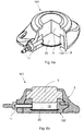
- Fig. 4a is a perspective view of a shielding plate 220.
- Fig. 4b is a perspective sectional view of lower housing 202 of an access port 201 comprising the shielding plate 220, with the shielding plate 220 shown unsectioned and lower housing 202 shown sectioned.
- Fig. 4c is a sectional view of the access port 201.
- the shielding plate 220 has a bent portion 224 in the form of three extensions 224 that are arranged on and spaced around the periphery 226 of the circular portion 222.
- the following elements of the shielding plate 220 are embedded into the lower housing 202: the lower side of the circular portion 222; the periphery 226; an annular region of the upper side of the circular portion 222, and all the surfaces of each extension 224.
- the elements mentioned above are in surface contact with the lower housing 202, thus providing a form-locking connection between shielding plate 220 and lower housing 202.
- the remaining region of the upper side of the shielding plate 220 is exposed to the reservoir 18.
- the shielding plate 220 preferably completely covers the inner base 6 of the reservoir 18.
- Each extension 224 is suitably sized with respect to the lower housing 202 so as not to obstruct the exit passage 10.
- the extensions 224 have the same thickness as the circular portion 222.
- the bending of the extensions 224 requires less effort than bending of the entire periphery of the shielding plate 120 of the embodiment.
- the shielding plate 220 has three axially extending extensions 224.
- the extensions 224 may serve to centre the shielding plate 220 on the first corepin 30 of the mold, preventing lateral movement and providing a clearer visual indication that the shielding plate 220 is correctly seated on the first corepin 30. Therefore the accuracy of location of the shielding plate 220 within the lower housing 202 is further improved and the manufacture of the access port 201 is further facilitated.
- each extension 224 may be suitably sized so as not to obstruct the exit passage 10 when any one of the extensions 224 is aligned with the exit passage 10. Therefore an arbitrary orientation of the shielding plate 220 with respect to the lower housing 202 is possible.
- a third explanatory example of the invention is described in the following, wherein the differences from the first explanatory example are described.
- Fig. 5a is a perspective view of a shielding plate 320.
- Fig. 5b is a perspective sectional view of a lower housing 302 of an access port 301 comprising the shielding plate 320, with the shielding plate 320 shown unsectioned and an lower housing 302 shown sectioned.
- Fig. 5c is a sectional view of the access port 301.
- the shielding plate 320 has a bent portion 324 in the form of three long extensions 324 that are arranged in a circular pattern on the circular portion 322, each long extension 324 extending along the majority of the axial length of the wall 4.
- the long extensions 324 are resiliently laterally deformable.
- each long extension 324 in its free state is inclined toward the axis of the reservoir 18, as can be seen most clearly in Fig. 5c .
- the lateral extent of each long extension 324 is less than the lateral extent of the circular portion 322.
- the diameter of the periphery 326 is preferably greater than the lateral extent of each long extension 324.
- the diameter of the periphery 326 of the circular portion 322 is preferably greater than the maximum internal diameter of the reservoir 18.
- recesses 328 each having the same angular position as a respective long extension 324, are formed on the periphery of the circular portion 122.
- the recesses 328 allow the plastic wall thickness of the wall 4 to be locally increased at the recesses 328 so as to be uninterrupted by the shielding plate 320.
- the following elements of the shielding plate 320 are embedded into the lower housing 302: the lower side of the circular portion 322; the periphery 326; an annular region of the upper side of the circular portion 322, and all the surfaces of each long extension 324.
- the elements mentioned above are in surface contact with the lower housing 302, thus providing a form-locking connection between shielding plate 320 and lower housing 302.
- the remaining region of the upper side of the shielding plate 320 is exposed to the reservoir 18.
- the shielding plate 320 preferably completely covers the inner base 6 of the reservoir 18.
- an orientation of the shielding plate 320 is chosen such that none of the long extensions 324 obstructs the exit passage 10.
- each long extension 324 has a minimum lateral dimension suitably sized to fit around the outer diameter of the lower face of the first corepin 30. In doing so, each long extension 324 contacts, and is preferably also biased against, the cylindrical surface of the first corepin 30. In order to ensure a sufficient locating effect, the long extensions 324 are preferably equispaced on the circular portion 322.
- the shielding plate 320 according to the third explanatory example has the following further advantages.
- the shielding plate 320 has three long extensions 324 that are arranged in a circular pattern on the circular portion 322, each extending over the majority of the axial length of the wall 4.
- the diameter of the periphery 326 of the circular portion 322 is preferably greater than the maximum internal diameter of the reservoir 18.
- recesses 328 are formed on the periphery 326 of the circular portion 322, which allow the uninterrupted plastic wall thickness of the wall 4 to be locally increased at these positions.
- the plastic material of the wall 4 is allowed to extend through and laterally beyond each recess 328. Therefore the overall strength of the wall 4 is maintained even when the diameter of the periphery 326 of the circular portion 322 is greater than the maximum internal diameter of the reservoir 18.
- reinforcing portions are created within the wall and the wall 4 is not excessively weakened by the embedding of part of the circular portion 322.
- each long extension 324 can be less than the diameter of the circular portion 322. Therefore the choice of diameter of the circular portion 322 is unconstrained by the positional requirements of the long extension.
- Each long extension 324 is inclined toward the axis of the reservoir 18.
- the wall thickness (marked “t” in Fig. 5c ) on the radially inner side of each the long extension 324 increases in an axial direction from the open end 7 towards the reservoir 18. Therefore the strength of the wall 4 is increased at the inner base 8 end, without the long extensions 324 interfering with the external features of the housing at the open end side such as the lug 14.
- the shielding plate 320 may be assembled to the lower housing 302 by the insert molding process described above.
- the long extensions 324 may serve to here to align the shielding plate 320 with respect to the first corepin 30 of the mold.
- Each long extension 324 may be inclined with respect to the cylindrical surface of the first corepin 30 such that only the tips of the long extensions 324 make contact with the first corepin 30.
- the long extensions 324 may be dimensioned to be biased against the surface of the first corepin 30. In this way axial alignment with the first corepin 30 is improved in comparison with the preceding embodiment and explanatory examples because lateral clearance between each long extension 324 and the first corepin 30 is reduced, preferably removed.
- Fig. 6a and 6b show the entire access port 1.
- Fig. 6a shows a perspective and partial sectional view of the access port 1 having the lower housing 102 according to the embodiment and an upper housing 3 that are connected to each other.
- the lower housing 102 is covered and surrounded by the upper housing 3.
- a circular septum 5 is sandwiched at circumferential portions thereof between the lower housing 102 and the upper housing 3.
- the septum 5 slightly protrudes from a central opening 9 provided in the upper housing 3 and is spaced apart from the shield member 120 embedded in the lower housing 102 so as to form the reservoir 18 therebetween.
- the upper housing 3 is configured to also be attached to or connected with any one of the lower housings 2, 202 and 302 according to the first, second and third explanatory examples.
- the access port has a single reservoir 18.
- the invention is not limited to single-reservoir access ports and it may be applied to access ports having more than one reservoir.
- the bent portion 124 extends all around the circular portion 122. In examples which do not form part of the invention the bent portion may extend around only a portion or portions of the circular portion.
- the extensions 224, 324 are equispaced and the number of extensions 224, 324 provided on the shielding plate 220, 320 is three.
- the example is not limited to this number of extensions and in addition the arrangement of extensions is not limited to being equispaced.
- the respective angles that the extensions 224, 324 make with the axial direction may differ.
- the long extensions 324 extend over the majority of the axial length of the reservoir 18.
- the example is not limited to this distance and the long extensions 324 may extend over the entire axial length of the wall 4.
- the recesses 328 are formed on the periphery 326 of the circular portion 322.
- the example is not limited to this configuration and the recesses may be formed within the circular portion 322.
- the molding method described above and shown in Figs. 3a to 3d is applied to the access port 101 according to the embodiment. However the method described herein may be applied to any of the above explanatory examples. In the case of insert molding, alignment of the shielding plate 20 on the first corepin 30 may be performed visually for example.
- an access port having a one-piece plastic lower housing, that comprises a shielding plate that is strongly anchored to the housing.
- the upper housing 3 is integrally formed with the lower housing 2, 102, 202, or 302 so as to form a single-unit molded housing in which the shielding plate 20 is embedded.
Claims (5)
- Zugangsöffnung (1; 101) mit einem geformten Gehäuseteil (2; 102) zur Bildung eines Reservoirs (18) zum Empfangen eines Fluids, wobei
das Gehäuseteil (2; 102) eine Schutzplatte (20; 120), die an einem inneren Boden (6) des Gehäuses (2) angeordnet ist, ein offenes Ende (7), in dem ein Septum (5) angeordnet ist, einen Austrittsdurchgang (10) und eine Wand (4) umfasst;
die Schutzplatte (20; 120) einen kreisförmigen Abschnitt (22; 122) mit einem Randbereich (26; 126) aufweist;
die untere Seite und der Randbereich (26; 126) der Schutzplatte (20; 120) in das Gehäuseteil (2; 102) eingebettet sind; und
die Schutzplatte (120) mit dem Gehäuseteil (102) umspritzt ist,
dadurch gekennzeichnet, dass
die Schutzplatte einen ringförmigen Bereich einschließlich eines gebogenen Teils (124) aufweist, der sich in axialer Richtung aufwärts und in Querrichtung nach außen erstreckt, wobei der gebogene Teil um den gesamten ringförmigen Bereich ausgebildet ist und an sämtlichen seiner Seiten in das Gehäuse eingebettet ist. - Zugangsöffnung (1; 101) nach Anspruch 1, wobei die Schutzplatte (20; 120) aus Metall oder Keramik besteht.
- Zugangsöffnung (1; 101) nach Anspruch 1, wobei der maximale Durchmesser des Randbereichs (126) des kreisförmigen Abschnitts (122) größer ist als der maximale innere Durchmesser des Reservoirs (18).
- Zugangsöffnung (1; 101) nach Anspruch 1 oder 3, wobei die obere Seite des kreisförmigen Abschnitts (22; 122) konkav ist.
- Verfahren zum Umspritzen der Schutzplatte (22; 122) in dem Gehäuseteil (102) der Zugangsöffnung (1; 101) gemäß Patentanspruch 1 oder 3, mit:in einem ersten Schritt (S1) Positionieren der Schutzplatte (22; 122) auf einem ersten Kernstift (30) eines Formungswerkzeugs mit einer Vertiefung;in einem zweiten Schritt (S2) Klemmen der Schutzplatte (22; 122) zwischen dem ersten Kernstift (30) und einem zweiten Kernstift (32) des Formungswerkzeugs;in einem dritten Schritt (S3) Einspritzen von Kunststoff in die Vertiefung zum Füllen der Vertiefung; undin einem vierten Schritt (S4) Zurückziehen des zweiten Kernstifts (32) zum Erzeugen eines Hohlraums und nachfolgendes Einspritzen von weiterem Kunststoff zum Füllen des Hohlraums.
Priority Applications (6)
| Application Number | Priority Date | Filing Date | Title |
|---|---|---|---|
| EP14184763.2A EP2995344B1 (de) | 2014-09-15 | 2014-09-15 | Zugangsöffnung mit umspritzter Schutzpatte |
| ES14184763T ES2715698T3 (es) | 2014-09-15 | 2014-09-15 | Puerto de acceso con placa de protección moldeada por inserción |
| JP2015172255A JP6649722B2 (ja) | 2014-09-15 | 2015-09-01 | アクセスポート |
| US14/848,753 US10086185B2 (en) | 2014-09-15 | 2015-09-09 | Access port |
| CN201510587348.XA CN105415591B (zh) | 2014-09-15 | 2015-09-15 | 出入端口 |
| US16/116,419 US20190076637A1 (en) | 2014-09-15 | 2018-08-29 | Method for insert molding a shielding plate into a housing portion of an access port |
Applications Claiming Priority (1)
| Application Number | Priority Date | Filing Date | Title |
|---|---|---|---|
| EP14184763.2A EP2995344B1 (de) | 2014-09-15 | 2014-09-15 | Zugangsöffnung mit umspritzter Schutzpatte |
Publications (2)
| Publication Number | Publication Date |
|---|---|
| EP2995344A1 EP2995344A1 (de) | 2016-03-16 |
| EP2995344B1 true EP2995344B1 (de) | 2019-01-16 |
Family
ID=51564479
Family Applications (1)
| Application Number | Title | Priority Date | Filing Date |
|---|---|---|---|
| EP14184763.2A Active EP2995344B1 (de) | 2014-09-15 | 2014-09-15 | Zugangsöffnung mit umspritzter Schutzpatte |
Country Status (5)
| Country | Link |
|---|---|
| US (2) | US10086185B2 (de) |
| EP (1) | EP2995344B1 (de) |
| JP (1) | JP6649722B2 (de) |
| CN (1) | CN105415591B (de) |
| ES (1) | ES2715698T3 (de) |
Families Citing this family (1)
| Publication number | Priority date | Publication date | Assignee | Title |
|---|---|---|---|---|
| JP7146045B1 (ja) * | 2021-10-12 | 2022-10-03 | 古河電気工業株式会社 | 医療器具および医療装置 |
Family Cites Families (18)
| Publication number | Priority date | Publication date | Assignee | Title |
|---|---|---|---|---|
| GB1156556A (en) * | 1965-10-12 | 1969-07-02 | Katashi Aoki | Injection Moulding of Composite trays and other articles |
| US4470786A (en) * | 1981-07-28 | 1984-09-11 | Omron Tateisi Electronics Co. | Molding apparatus with retractable preform support pins |
| US4802885A (en) | 1986-06-17 | 1989-02-07 | Medical Engineering Corporation | Self sealing subcutaneous infusion and withdrawal device |
| DE3628337A1 (de) | 1986-08-21 | 1988-02-25 | Braun Melsungen Ag | Implantierbare kathetervorrichtung |
| US4904241A (en) * | 1986-10-16 | 1990-02-27 | Medical Engineering Corp. | Septum with a needle stop at the fluid transfer port |
| US5213574A (en) * | 1991-09-06 | 1993-05-25 | Device Labs, Inc. | Composite implantable biocompatible vascular access port device |
| JPH08227637A (ja) * | 1994-02-23 | 1996-09-03 | Matsushita Electric Works Ltd | コントロールスイッチ及びその製造方法 |
| US6527754B1 (en) | 1998-12-07 | 2003-03-04 | Std Manufacturing, Inc. | Implantable vascular access device |
| JP4576024B2 (ja) * | 2000-05-31 | 2010-11-04 | トヨタ紡織株式会社 | 表皮一体成形品の製造方法および装置 |
| US8029482B2 (en) | 2005-03-04 | 2011-10-04 | C. R. Bard, Inc. | Systems and methods for radiographically identifying an access port |
| US7651483B2 (en) * | 2005-06-24 | 2010-01-26 | Ethicon Endo-Surgery, Inc. | Injection port |
| US8021324B2 (en) | 2007-07-19 | 2011-09-20 | Medical Components, Inc. | Venous access port assembly with X-ray discernable indicia |
| US8075536B2 (en) | 2008-09-09 | 2011-12-13 | Navilyst Medical, Inc. | Power injectable port identification |
| BRPI0919890B8 (pt) | 2008-10-31 | 2019-09-24 | Bard Inc C R | orifício de acesso para prover acesso subcutâneo a um paciente, e, orifício de acesso injetável de força |
| JP2010234641A (ja) * | 2009-03-31 | 2010-10-21 | Honda Motor Co Ltd | インサート成形方法及び装置 |
| JP5706113B2 (ja) * | 2010-08-26 | 2015-04-22 | 日本コヴィディエン株式会社 | 皮下埋込ポートの製造方法 |
| JP5606855B2 (ja) * | 2010-09-29 | 2014-10-15 | 日本コヴィディエン株式会社 | 皮下埋込ポート及びその製造方法 |
| JP5612990B2 (ja) * | 2010-09-30 | 2014-10-22 | 日本コヴィディエン株式会社 | 皮下埋込ポート構成部品用の成形金型、皮下埋込ポート及びその製造方法 |
-
2014
- 2014-09-15 EP EP14184763.2A patent/EP2995344B1/de active Active
- 2014-09-15 ES ES14184763T patent/ES2715698T3/es active Active
-
2015
- 2015-09-01 JP JP2015172255A patent/JP6649722B2/ja active Active
- 2015-09-09 US US14/848,753 patent/US10086185B2/en active Active
- 2015-09-15 CN CN201510587348.XA patent/CN105415591B/zh active Active
-
2018
- 2018-08-29 US US16/116,419 patent/US20190076637A1/en active Pending
Non-Patent Citations (1)
| Title |
|---|
| None * |
Also Published As
| Publication number | Publication date |
|---|---|
| EP2995344A1 (de) | 2016-03-16 |
| ES2715698T3 (es) | 2019-06-05 |
| US20160074647A1 (en) | 2016-03-17 |
| JP6649722B2 (ja) | 2020-02-19 |
| CN105415591A (zh) | 2016-03-23 |
| US20190076637A1 (en) | 2019-03-14 |
| US10086185B2 (en) | 2018-10-02 |
| CN105415591B (zh) | 2019-10-25 |
| JP2016059801A (ja) | 2016-04-25 |
Similar Documents
| Publication | Publication Date | Title |
|---|---|---|
| US20210093847A1 (en) | Venous Access Port Assembly With X-Ray Discernable Indicia | |
| US20070270770A1 (en) | Venous access port assembly and method of making same | |
| CA2692142C (en) | Venous access port with molded and/or radiopaque indicia | |
| US8608712B2 (en) | Septum for venous access port assembly | |
| US8366687B2 (en) | Injection access port with chamfered top hat septum design | |
| JP2010530787A (ja) | 低プロファイル静脈アクセスポートアセンブリ | |
| EP1566193A1 (de) | Infusionsvorrichtung mit Gehäuse für das Septum | |
| US20190076637A1 (en) | Method for insert molding a shielding plate into a housing portion of an access port | |
| JP6337651B2 (ja) | 薬液注入ポートおよび薬液注入ポートの製造方法 |
Legal Events
| Date | Code | Title | Description |
|---|---|---|---|
| PUAI | Public reference made under article 153(3) epc to a published international application that has entered the european phase |
Free format text: ORIGINAL CODE: 0009012 |
|
| AK | Designated contracting states |
Kind code of ref document: A1 Designated state(s): AL AT BE BG CH CY CZ DE DK EE ES FI FR GB GR HR HU IE IS IT LI LT LU LV MC MK MT NL NO PL PT RO RS SE SI SK SM TR |
|
| AX | Request for extension of the european patent |
Extension state: BA ME |
|
| 17P | Request for examination filed |
Effective date: 20160614 |
|
| RBV | Designated contracting states (corrected) |
Designated state(s): AL AT BE BG CH CY CZ DE DK EE ES FI FR GB GR HR HU IE IS IT LI LT LU LV MC MK MT NL NO PL PT RO RS SE SI SK SM TR |
|
| GRAP | Despatch of communication of intention to grant a patent |
Free format text: ORIGINAL CODE: EPIDOSNIGR1 |
|
| STAA | Information on the status of an ep patent application or granted ep patent |
Free format text: STATUS: GRANT OF PATENT IS INTENDED |
|
| INTG | Intention to grant announced |
Effective date: 20180618 |
|
| GRAJ | Information related to disapproval of communication of intention to grant by the applicant or resumption of examination proceedings by the epo deleted |
Free format text: ORIGINAL CODE: EPIDOSDIGR1 |
|
| STAA | Information on the status of an ep patent application or granted ep patent |
Free format text: STATUS: REQUEST FOR EXAMINATION WAS MADE |
|
| GRAR | Information related to intention to grant a patent recorded |
Free format text: ORIGINAL CODE: EPIDOSNIGR71 |
|
| GRAS | Grant fee paid |
Free format text: ORIGINAL CODE: EPIDOSNIGR3 |
|
| INTC | Intention to grant announced (deleted) | ||
| STAA | Information on the status of an ep patent application or granted ep patent |
Free format text: STATUS: GRANT OF PATENT IS INTENDED |
|
| GRAA | (expected) grant |
Free format text: ORIGINAL CODE: 0009210 |
|
| STAA | Information on the status of an ep patent application or granted ep patent |
Free format text: STATUS: THE PATENT HAS BEEN GRANTED |
|
| INTG | Intention to grant announced |
Effective date: 20181205 |
|
| AK | Designated contracting states |
Kind code of ref document: B1 Designated state(s): AL AT BE BG CH CY CZ DE DK EE ES FI FR GB GR HR HU IE IS IT LI LT LU LV MC MK MT NL NO PL PT RO RS SE SI SK SM TR |
|
| REG | Reference to a national code |
Ref country code: GB Ref legal event code: FG4D |
|
| REG | Reference to a national code |
Ref country code: CH Ref legal event code: EP |
|
| REG | Reference to a national code |
Ref country code: IE Ref legal event code: FG4D |
|
| REG | Reference to a national code |
Ref country code: DE Ref legal event code: R096 Ref document number: 602014039921 Country of ref document: DE |
|
| REG | Reference to a national code |
Ref country code: AT Ref legal event code: REF Ref document number: 1089231 Country of ref document: AT Kind code of ref document: T Effective date: 20190215 |
|
| REG | Reference to a national code |
Ref country code: NL Ref legal event code: MP Effective date: 20190116 |
|
| REG | Reference to a national code |
Ref country code: ES Ref legal event code: FG2A Ref document number: 2715698 Country of ref document: ES Kind code of ref document: T3 Effective date: 20190605 |
|
| REG | Reference to a national code |
Ref country code: LT Ref legal event code: MG4D |
|
| PG25 | Lapsed in a contracting state [announced via postgrant information from national office to epo] |
Ref country code: NL Free format text: LAPSE BECAUSE OF FAILURE TO SUBMIT A TRANSLATION OF THE DESCRIPTION OR TO PAY THE FEE WITHIN THE PRESCRIBED TIME-LIMIT Effective date: 20190116 |
|
| REG | Reference to a national code |
Ref country code: AT Ref legal event code: MK05 Ref document number: 1089231 Country of ref document: AT Kind code of ref document: T Effective date: 20190116 |
|
| PG25 | Lapsed in a contracting state [announced via postgrant information from national office to epo] |
Ref country code: PT Free format text: LAPSE BECAUSE OF FAILURE TO SUBMIT A TRANSLATION OF THE DESCRIPTION OR TO PAY THE FEE WITHIN THE PRESCRIBED TIME-LIMIT Effective date: 20190516 Ref country code: SE Free format text: LAPSE BECAUSE OF FAILURE TO SUBMIT A TRANSLATION OF THE DESCRIPTION OR TO PAY THE FEE WITHIN THE PRESCRIBED TIME-LIMIT Effective date: 20190116 Ref country code: FI Free format text: LAPSE BECAUSE OF FAILURE TO SUBMIT A TRANSLATION OF THE DESCRIPTION OR TO PAY THE FEE WITHIN THE PRESCRIBED TIME-LIMIT Effective date: 20190116 Ref country code: NO Free format text: LAPSE BECAUSE OF FAILURE TO SUBMIT A TRANSLATION OF THE DESCRIPTION OR TO PAY THE FEE WITHIN THE PRESCRIBED TIME-LIMIT Effective date: 20190416 Ref country code: PL Free format text: LAPSE BECAUSE OF FAILURE TO SUBMIT A TRANSLATION OF THE DESCRIPTION OR TO PAY THE FEE WITHIN THE PRESCRIBED TIME-LIMIT Effective date: 20190116 Ref country code: LT Free format text: LAPSE BECAUSE OF FAILURE TO SUBMIT A TRANSLATION OF THE DESCRIPTION OR TO PAY THE FEE WITHIN THE PRESCRIBED TIME-LIMIT Effective date: 20190116 |
|
| PG25 | Lapsed in a contracting state [announced via postgrant information from national office to epo] |
Ref country code: BG Free format text: LAPSE BECAUSE OF FAILURE TO SUBMIT A TRANSLATION OF THE DESCRIPTION OR TO PAY THE FEE WITHIN THE PRESCRIBED TIME-LIMIT Effective date: 20190416 Ref country code: GR Free format text: LAPSE BECAUSE OF FAILURE TO SUBMIT A TRANSLATION OF THE DESCRIPTION OR TO PAY THE FEE WITHIN THE PRESCRIBED TIME-LIMIT Effective date: 20190417 Ref country code: LV Free format text: LAPSE BECAUSE OF FAILURE TO SUBMIT A TRANSLATION OF THE DESCRIPTION OR TO PAY THE FEE WITHIN THE PRESCRIBED TIME-LIMIT Effective date: 20190116 Ref country code: HR Free format text: LAPSE BECAUSE OF FAILURE TO SUBMIT A TRANSLATION OF THE DESCRIPTION OR TO PAY THE FEE WITHIN THE PRESCRIBED TIME-LIMIT Effective date: 20190116 Ref country code: RS Free format text: LAPSE BECAUSE OF FAILURE TO SUBMIT A TRANSLATION OF THE DESCRIPTION OR TO PAY THE FEE WITHIN THE PRESCRIBED TIME-LIMIT Effective date: 20190116 Ref country code: IS Free format text: LAPSE BECAUSE OF FAILURE TO SUBMIT A TRANSLATION OF THE DESCRIPTION OR TO PAY THE FEE WITHIN THE PRESCRIBED TIME-LIMIT Effective date: 20190516 |
|
| REG | Reference to a national code |
Ref country code: DE Ref legal event code: R097 Ref document number: 602014039921 Country of ref document: DE |
|
| PG25 | Lapsed in a contracting state [announced via postgrant information from national office to epo] |
Ref country code: SK Free format text: LAPSE BECAUSE OF FAILURE TO SUBMIT A TRANSLATION OF THE DESCRIPTION OR TO PAY THE FEE WITHIN THE PRESCRIBED TIME-LIMIT Effective date: 20190116 Ref country code: RO Free format text: LAPSE BECAUSE OF FAILURE TO SUBMIT A TRANSLATION OF THE DESCRIPTION OR TO PAY THE FEE WITHIN THE PRESCRIBED TIME-LIMIT Effective date: 20190116 Ref country code: CZ Free format text: LAPSE BECAUSE OF FAILURE TO SUBMIT A TRANSLATION OF THE DESCRIPTION OR TO PAY THE FEE WITHIN THE PRESCRIBED TIME-LIMIT Effective date: 20190116 Ref country code: EE Free format text: LAPSE BECAUSE OF FAILURE TO SUBMIT A TRANSLATION OF THE DESCRIPTION OR TO PAY THE FEE WITHIN THE PRESCRIBED TIME-LIMIT Effective date: 20190116 Ref country code: AT Free format text: LAPSE BECAUSE OF FAILURE TO SUBMIT A TRANSLATION OF THE DESCRIPTION OR TO PAY THE FEE WITHIN THE PRESCRIBED TIME-LIMIT Effective date: 20190116 Ref country code: DK Free format text: LAPSE BECAUSE OF FAILURE TO SUBMIT A TRANSLATION OF THE DESCRIPTION OR TO PAY THE FEE WITHIN THE PRESCRIBED TIME-LIMIT Effective date: 20190116 Ref country code: AL Free format text: LAPSE BECAUSE OF FAILURE TO SUBMIT A TRANSLATION OF THE DESCRIPTION OR TO PAY THE FEE WITHIN THE PRESCRIBED TIME-LIMIT Effective date: 20190116 |
|
| PLBE | No opposition filed within time limit |
Free format text: ORIGINAL CODE: 0009261 |
|
| STAA | Information on the status of an ep patent application or granted ep patent |
Free format text: STATUS: NO OPPOSITION FILED WITHIN TIME LIMIT |
|
| PG25 | Lapsed in a contracting state [announced via postgrant information from national office to epo] |
Ref country code: SM Free format text: LAPSE BECAUSE OF FAILURE TO SUBMIT A TRANSLATION OF THE DESCRIPTION OR TO PAY THE FEE WITHIN THE PRESCRIBED TIME-LIMIT Effective date: 20190116 |
|
| 26N | No opposition filed |
Effective date: 20191017 |
|
| PG25 | Lapsed in a contracting state [announced via postgrant information from national office to epo] |
Ref country code: SI Free format text: LAPSE BECAUSE OF FAILURE TO SUBMIT A TRANSLATION OF THE DESCRIPTION OR TO PAY THE FEE WITHIN THE PRESCRIBED TIME-LIMIT Effective date: 20190116 |
|
| PG25 | Lapsed in a contracting state [announced via postgrant information from national office to epo] |
Ref country code: TR Free format text: LAPSE BECAUSE OF FAILURE TO SUBMIT A TRANSLATION OF THE DESCRIPTION OR TO PAY THE FEE WITHIN THE PRESCRIBED TIME-LIMIT Effective date: 20190116 |
|
| PG25 | Lapsed in a contracting state [announced via postgrant information from national office to epo] |
Ref country code: MC Free format text: LAPSE BECAUSE OF FAILURE TO SUBMIT A TRANSLATION OF THE DESCRIPTION OR TO PAY THE FEE WITHIN THE PRESCRIBED TIME-LIMIT Effective date: 20190116 |
|
| REG | Reference to a national code |
Ref country code: CH Ref legal event code: PL |
|
| PG25 | Lapsed in a contracting state [announced via postgrant information from national office to epo] |
Ref country code: CH Free format text: LAPSE BECAUSE OF NON-PAYMENT OF DUE FEES Effective date: 20190930 Ref country code: LU Free format text: LAPSE BECAUSE OF NON-PAYMENT OF DUE FEES Effective date: 20190915 Ref country code: IE Free format text: LAPSE BECAUSE OF NON-PAYMENT OF DUE FEES Effective date: 20190915 Ref country code: LI Free format text: LAPSE BECAUSE OF NON-PAYMENT OF DUE FEES Effective date: 20190930 |
|
| REG | Reference to a national code |
Ref country code: BE Ref legal event code: MM Effective date: 20190930 |
|
| PG25 | Lapsed in a contracting state [announced via postgrant information from national office to epo] |
Ref country code: BE Free format text: LAPSE BECAUSE OF NON-PAYMENT OF DUE FEES Effective date: 20190930 |
|
| GBPC | Gb: european patent ceased through non-payment of renewal fee |
Effective date: 20190915 |
|
| PG25 | Lapsed in a contracting state [announced via postgrant information from national office to epo] |
Ref country code: GB Free format text: LAPSE BECAUSE OF NON-PAYMENT OF DUE FEES Effective date: 20190915 |
|
| PG25 | Lapsed in a contracting state [announced via postgrant information from national office to epo] |
Ref country code: CY Free format text: LAPSE BECAUSE OF FAILURE TO SUBMIT A TRANSLATION OF THE DESCRIPTION OR TO PAY THE FEE WITHIN THE PRESCRIBED TIME-LIMIT Effective date: 20190116 |
|
| PG25 | Lapsed in a contracting state [announced via postgrant information from national office to epo] |
Ref country code: MT Free format text: LAPSE BECAUSE OF FAILURE TO SUBMIT A TRANSLATION OF THE DESCRIPTION OR TO PAY THE FEE WITHIN THE PRESCRIBED TIME-LIMIT Effective date: 20190116 Ref country code: HU Free format text: LAPSE BECAUSE OF FAILURE TO SUBMIT A TRANSLATION OF THE DESCRIPTION OR TO PAY THE FEE WITHIN THE PRESCRIBED TIME-LIMIT; INVALID AB INITIO Effective date: 20140915 |
|
| PG25 | Lapsed in a contracting state [announced via postgrant information from national office to epo] |
Ref country code: MK Free format text: LAPSE BECAUSE OF FAILURE TO SUBMIT A TRANSLATION OF THE DESCRIPTION OR TO PAY THE FEE WITHIN THE PRESCRIBED TIME-LIMIT Effective date: 20190116 |
|
| PGFP | Annual fee paid to national office [announced via postgrant information from national office to epo] |
Ref country code: FR Payment date: 20230918 Year of fee payment: 10 Ref country code: DE Payment date: 20230919 Year of fee payment: 10 |
|
| PGFP | Annual fee paid to national office [announced via postgrant information from national office to epo] |
Ref country code: ES Payment date: 20231019 Year of fee payment: 10 |
|
| PGFP | Annual fee paid to national office [announced via postgrant information from national office to epo] |
Ref country code: IT Payment date: 20230929 Year of fee payment: 10 |