EP2994331B1 - Verfahren zum steuern einer anzeigefläche einer bedienvorrichtung und bedienvorrichtung in einem fahrzeug - Google Patents
Verfahren zum steuern einer anzeigefläche einer bedienvorrichtung und bedienvorrichtung in einem fahrzeug Download PDFInfo
- Publication number
- EP2994331B1 EP2994331B1 EP14721329.2A EP14721329A EP2994331B1 EP 2994331 B1 EP2994331 B1 EP 2994331B1 EP 14721329 A EP14721329 A EP 14721329A EP 2994331 B1 EP2994331 B1 EP 2994331B1
- Authority
- EP
- European Patent Office
- Prior art keywords
- vehicle
- displayed
- type
- display
- specific information
- Prior art date
- Legal status (The legal status is an assumption and is not a legal conclusion. Google has not performed a legal analysis and makes no representation as to the accuracy of the status listed.)
- Active
Links
- 238000000034 method Methods 0.000 title claims description 32
- 238000001514 detection method Methods 0.000 claims description 92
- 230000005855 radiation Effects 0.000 description 8
- 230000008859 change Effects 0.000 description 6
- 230000006870 function Effects 0.000 description 4
- 238000013459 approach Methods 0.000 description 3
- 230000033001 locomotion Effects 0.000 description 2
- 230000004888 barrier function Effects 0.000 description 1
- 238000004891 communication Methods 0.000 description 1
- 230000001419 dependent effect Effects 0.000 description 1
- 238000011161 development Methods 0.000 description 1
- 230000018109 developmental process Effects 0.000 description 1
- 230000000694 effects Effects 0.000 description 1
- 239000004973 liquid crystal related substance Substances 0.000 description 1
- 239000011159 matrix material Substances 0.000 description 1
- 230000007704 transition Effects 0.000 description 1
- 238000012800 visualization Methods 0.000 description 1
Images


Classifications
-
- B—PERFORMING OPERATIONS; TRANSPORTING
- B60—VEHICLES IN GENERAL
- B60K—ARRANGEMENT OR MOUNTING OF PROPULSION UNITS OR OF TRANSMISSIONS IN VEHICLES; ARRANGEMENT OR MOUNTING OF PLURAL DIVERSE PRIME-MOVERS IN VEHICLES; AUXILIARY DRIVES FOR VEHICLES; INSTRUMENTATION OR DASHBOARDS FOR VEHICLES; ARRANGEMENTS IN CONNECTION WITH COOLING, AIR INTAKE, GAS EXHAUST OR FUEL SUPPLY OF PROPULSION UNITS IN VEHICLES
- B60K35/00—Instruments specially adapted for vehicles; Arrangement of instruments in or on vehicles
- B60K35/10—Input arrangements, i.e. from user to vehicle, associated with vehicle functions or specially adapted therefor
-
- G—PHYSICS
- G06—COMPUTING; CALCULATING OR COUNTING
- G06F—ELECTRIC DIGITAL DATA PROCESSING
- G06F3/00—Input arrangements for transferring data to be processed into a form capable of being handled by the computer; Output arrangements for transferring data from processing unit to output unit, e.g. interface arrangements
- G06F3/01—Input arrangements or combined input and output arrangements for interaction between user and computer
- G06F3/048—Interaction techniques based on graphical user interfaces [GUI]
- G06F3/0481—Interaction techniques based on graphical user interfaces [GUI] based on specific properties of the displayed interaction object or a metaphor-based environment, e.g. interaction with desktop elements like windows or icons, or assisted by a cursor's changing behaviour or appearance
- G06F3/0482—Interaction with lists of selectable items, e.g. menus
-
- G—PHYSICS
- G06—COMPUTING; CALCULATING OR COUNTING
- G06F—ELECTRIC DIGITAL DATA PROCESSING
- G06F3/00—Input arrangements for transferring data to be processed into a form capable of being handled by the computer; Output arrangements for transferring data from processing unit to output unit, e.g. interface arrangements
- G06F3/01—Input arrangements or combined input and output arrangements for interaction between user and computer
- G06F3/048—Interaction techniques based on graphical user interfaces [GUI]
- G06F3/0487—Interaction techniques based on graphical user interfaces [GUI] using specific features provided by the input device, e.g. functions controlled by the rotation of a mouse with dual sensing arrangements, or of the nature of the input device, e.g. tap gestures based on pressure sensed by a digitiser
- G06F3/0488—Interaction techniques based on graphical user interfaces [GUI] using specific features provided by the input device, e.g. functions controlled by the rotation of a mouse with dual sensing arrangements, or of the nature of the input device, e.g. tap gestures based on pressure sensed by a digitiser using a touch-screen or digitiser, e.g. input of commands through traced gestures
-
- B—PERFORMING OPERATIONS; TRANSPORTING
- B60—VEHICLES IN GENERAL
- B60K—ARRANGEMENT OR MOUNTING OF PROPULSION UNITS OR OF TRANSMISSIONS IN VEHICLES; ARRANGEMENT OR MOUNTING OF PLURAL DIVERSE PRIME-MOVERS IN VEHICLES; AUXILIARY DRIVES FOR VEHICLES; INSTRUMENTATION OR DASHBOARDS FOR VEHICLES; ARRANGEMENTS IN CONNECTION WITH COOLING, AIR INTAKE, GAS EXHAUST OR FUEL SUPPLY OF PROPULSION UNITS IN VEHICLES
- B60K2360/00—Indexing scheme associated with groups B60K35/00 or B60K37/00 relating to details of instruments or dashboards
- B60K2360/11—Instrument graphical user interfaces or menu aspects
-
- B—PERFORMING OPERATIONS; TRANSPORTING
- B60—VEHICLES IN GENERAL
- B60K—ARRANGEMENT OR MOUNTING OF PROPULSION UNITS OR OF TRANSMISSIONS IN VEHICLES; ARRANGEMENT OR MOUNTING OF PLURAL DIVERSE PRIME-MOVERS IN VEHICLES; AUXILIARY DRIVES FOR VEHICLES; INSTRUMENTATION OR DASHBOARDS FOR VEHICLES; ARRANGEMENTS IN CONNECTION WITH COOLING, AIR INTAKE, GAS EXHAUST OR FUEL SUPPLY OF PROPULSION UNITS IN VEHICLES
- B60K2360/00—Indexing scheme associated with groups B60K35/00 or B60K37/00 relating to details of instruments or dashboards
- B60K2360/141—Activation of instrument input devices by approaching fingers or pens
-
- B—PERFORMING OPERATIONS; TRANSPORTING
- B60—VEHICLES IN GENERAL
- B60K—ARRANGEMENT OR MOUNTING OF PROPULSION UNITS OR OF TRANSMISSIONS IN VEHICLES; ARRANGEMENT OR MOUNTING OF PLURAL DIVERSE PRIME-MOVERS IN VEHICLES; AUXILIARY DRIVES FOR VEHICLES; INSTRUMENTATION OR DASHBOARDS FOR VEHICLES; ARRANGEMENTS IN CONNECTION WITH COOLING, AIR INTAKE, GAS EXHAUST OR FUEL SUPPLY OF PROPULSION UNITS IN VEHICLES
- B60K2360/00—Indexing scheme associated with groups B60K35/00 or B60K37/00 relating to details of instruments or dashboards
- B60K2360/143—Touch sensitive instrument input devices
- B60K2360/1438—Touch screens
Definitions
- the present invention relates to a method for controlling a display area of an operating device in a vehicle.
- Data is stored in a memory for a menu structure which has different menus, in particular data for a hierarchical menu structure which has menus in different levels.
- the invention further relates to an operating device in a vehicle with a display area and a memory in which the aforementioned data are stored.
- the operating device further comprises a control device which is coupled to the memory and the display area and by means of which graphic data can be generated for display on the display area.
- the operating device comprises a proximity detection device for detecting the location of an actuation object in a detection area.
- a hierarchical menu structure contains a large number of menus, each of which is assigned different menu items, alphanumeric information displays and / or graphics.
- a menu opens at a lower level in the hierarchical menu structure, a so-called submenu. This submenu in turn comprises several submenu items.
- This structure can be continued over several hierarchy levels, so that there is a complex ramification for the display on the display area.
- the user should be able to operate the operating device in the vehicle simply and intuitively.
- a method for providing an operating device in a vehicle in which graphic data are generated by a control device, which control a display area in such a way that a plurality of graphic objects can be represented in at least two display modes. Furthermore, an operating status is defined for the display on the display surface.
- the control device changes from a display state to the operating state when the actuation object has been detected in the detection area.
- the WO 2013/053466 A2 describes a method for controlling a display area and an operating device, wherein graphic objects can be displayed on a display area in at least two display modes, namely arranged in a row or in a matrix. A position of an actuating object relative to a button is detected and evaluated as an actuation. An animated transition between the display modes is then shown.
- the present invention is based on the object of providing a method and an operating device of the type mentioned at the outset, in which information of a menu structure is displayed to the user in such a way that this information is easy to grasp, but likewise the vehicle type-specific information is conveyed to the user.
- the presence of an actuating object in a detection area is recorded.
- the menus of the menu structure include a sub-area for displaying vehicle-type-specific information.
- the partial area with this vehicle type-specific information is only displayed or changed in the associated menu on the display area if it has been detected that the actuating object is entering the detection area or is leaving the detection area.
- the partial area with the vehicle type-specific information is also not shown on the display area.
- the display of the current menu changes in such a way that the partial area is displayed with the vehicle-type-specific information.
- the partial area with the vehicle-type-specific information can only be displayed if it has been detected that the actuating object exits the detection area.
- the partial area with the vehicle-type-specific information is not displayed when the actuation object enters the detection area.
- the partial area is only displayed, for example, for a specific time interval when it exits, in order to briefly convey the vehicle-type-specific information to the user.
- the sub-area changes with the vehicle-type-specific information, which can result when the actuation object enters the detection area or when the actuation object exits the detection area, the sub-area is displayed enlarged, in particular for a certain time, in order to inform the user of the vehicle-type-specific To draw attention to information.
- the vehicle-type-specific information can be, for example, a specific graphic, a special image or a lettering which is only used in connection with a specific vehicle type.
- This vehicle-type-specific information can in particular indicate that the vehicle has an electric drive for locomotion with the vehicle.
- the partial area with the vehicle type-specific information is displayed in the associated menu when it has been detected that the actuation object is in the detection area.
- an intention to operate the user can be concluded.
- the user views the display area at least temporarily.
- the partial area with the vehicle-type-specific information which is displayed in particular in connection with all the menus in the menu structure, the driver is repeatedly given a special visualization for the type of vehicle. If the actuation object is outside the detection range, it can be concluded that the user has no intention to operate.
- the partial area with the vehicle-type-specific information is in particular not displayed, so that a larger display area remains for the display of the current menu. This enables the user to capture the information in the menu more quickly and easily.
- the partial area with the vehicle type-specific information is displayed in the associated menu for a first time interval after the actuation object has entered the detection area or for a second time interval after the actuation object has left the detection area.
- the two time intervals of these alternatives can in particular be identical. With both alternatives, the user is in one Situation in which an operation will be carried out shortly or in which an operation has just been carried out, the partial area with the vehicle-type-specific information is displayed for a time interval. In this way, the user is briefly but repeatedly made aware of the current type of vehicle.
- the detection area is arranged in front of an input device.
- the detection area preferably not only the presence of an actuation object in the detection area but also the position of the actuation object in the detection area is detected.
- the partial area with the vehicle-type-specific information is only displayed or changed in the associated menu if it has been detected that the actuation object is approaching the input device or that the actuation object is moving away from the input device. The result of this is that it can be ascertained even more precisely whether the user intends to input or whether the input of a user has been completed.
- the partial area for displaying the vehicle-type-specific information is displayed in the representations of all menus.
- the way in which the vehicle-type-specific information is displayed changes when it has been detected that the actuating object is entering the detection area or is leaving the detection area.
- the color of the display in the partial area can change.
- the size of the partial area can change, in particular enlarge.
- this screen saver comprises the display of the vehicle-type-specific information. If it has been detected that the actuation object is approaching the input device, the screen saver disappears again and a menu appears in which the partial area for displaying the vehicle-type-specific information may be displayed.
- the partial area is a switching element of the menu of the menu structure shown in each case.
- the vehicle-type-specific information or further vehicle-type-specific information is then displayed.
- the vehicle-type-specific information is only fully displayed when the switching element is actuated. In this case, a larger display area is advantageously available for displaying this information.
- a switching element is understood to mean a control element of a graphical user interface.
- a switching element differs from elements and areas for pure information display, so-called display elements, in that they can be selected.
- display elements When a switching element is selected, a function assigned to it is carried out. The function can only change the information display.
- the switching elements can be used to control devices whose operation is supported by the information display. The switching elements can thus replace conventional mechanical switches.
- the switching elements can be generated for a freely programmable display area and displayed by it. Furthermore, it can be provided that a switching element can be marked. In this case, the assigned function is not yet carried out. However, the selected switching element is highlighted compared to other switching elements.
- the function assigned to it is only executed when the switching element is selected.
- the actuation object which is used in the method according to the invention can be, for example, the fingertip of a user, an actuation pen or some other object.
- a display surface is used, on which a touch-sensitive surface is formed. A so-called touchscreen is therefore used.
- the graphic data for the display of the menus of the menu structure can be generated by means of the control device in such a way that a partial area with the vehicle type-specific information is only displayed or changed in the associated menu when it has been detected that the actuation object enters the detection area or emerges from the detection area.
- the operating device has an input device with which inputs for the operating device can be recorded.
- the control device can be used to display the partial area with the vehicle-type-specific information in the associated menu for a first time interval after the actuation object has entered the detection area or for a second time interval after the actuation object has left the detection area.
- a screen saver can be displayed by means of the control device if it has been detected that no entries have been made within a third time interval, the screen saver comprising the display of the vehicle-type-specific information.
- the operating device according to the invention is in particular designed in such a way that it can partially or completely carry out the aforementioned method steps.
- Various devices of the vehicle can be operated by means of the operating device.
- the operating device according to the invention has the same advantages mentioned above as the method according to the invention.
- the operating device has in particular an input device in front of which the detection area is arranged.
- the position of the actuating object in the detection area can in particular be detected by means of the proximity detection device.
- the input device comprises in particular a touch-sensitive surface which is arranged on the display surface. A so-called touchscreen is thus provided.
- the proximity detection device is known per se.
- it can comprise a reflection light barrier, which comprise at least one illuminant for emitting electromagnetic detection radiation into the detection area and a receiving element for detecting a portion of the detection radiation that is scattered and / or reflected on the actuation object.
- the proximity detection device can further comprise different illuminants for the individual detection zones, each of which emits electromagnetic detection radiation into the respective detection zone.
- a modulation device can be provided for modulating the emitted detection radiation, so that the detection radiation that is emitted into the individual detection zones differs in terms of its modulation.
- the proximity detection device can also comprise an analysis unit which is designed such that the received reflected and / or scattered detection radiation can be analyzed with regard to its modulation in order to determine in which detection zone the detection radiation was scattered or reflected on an actuating object.
- the invention relates to a vehicle with the operating device according to the invention.
- the display area is arranged in such a way that it can be easily reached by the driver and / or the passenger.
- the display area is arranged in the center console of the vehicle.
- the operating device 6 comprises a display device 1 with a display surface 2, which is arranged in the interior of the vehicle 20 such that it is clearly visible to at least one vehicle occupant, in particular the driver.
- the display surface 2 can be provided by any type of display, in particular a liquid crystal display.
- the operating device 6 further comprises a control device 3 and an input device 4.
- the control device 3 is connected to the display device 1.
- the control device 3 can be used to generate graphic data for displaying information on the display surface 2.
- the input device is designed as a touch-sensitive surface 4 on the display surface 2. A so-called touchscreen is thus provided.
- the operating device 6 comprises a proximity detection device 7.
- the proximity and preferably the position of an actuation object 12 in a detection area 8 can be detected by means of the proximity detection device 7.
- the detection area 8 is in Fig. 2 presented in detail.
- the detection area 8 is formed in such a way that an approach of an actuation object 12 to the touch-sensitive surface 4 on the display surface 2 is detected.
- the detection area 8 forms at least one volume in front of the user interface 4.
- a cuboid is formed, which extends with its side faces parallel to the touch-sensitive surface 4 runs, completely encloses the touch-sensitive surface 4.
- the cuboid extends from the touch-sensitive surface 4 or immediately in front of the touch-sensitive surface 4 to a distance of e.g. B. about 40 cm.
- the distance of the outer boundary of the detection area 8 in front of the touch-sensitive surface 4 is chosen so that an approach to the touch-sensitive surface 4 can be detected in time so that the display on the display surface 2 can be changed early enough for the user to see Support input.
- the distance of the detection area 8 from the touch-sensitive surface 4 should be selected such that the actuation object 12 or another object is moved into the detection area 8 as rarely as possible if no operation of the touch-sensitive surface 4 is intended.
- the proximity detection device 7 continuously transmits the current position of an actuating object 12 in the detection area 8 to the control device 3. Depending on this signal, the control device 3 can change the display on the display surface 2.
- the control device 3 is also connected to a memory 11.
- Data relating to a hierarchical menu structure, which has menus in different levels, are stored in the memory 11.
- the hierarchical menu structure has a main menu which is displayed when the operating device 6 is switched on or when the vehicle 20 is switched on.
- This main menu comprises several menu items.
- the menu items are designed as switching elements on the display surface 2. If such a switching element is confirmed, a submenu, that is to say a menu of a hierarchically lower level, is then displayed, which can again comprise several menu items.
- information can be displayed in the menus or after actuation of a menu item, which serve to operate devices of the vehicle or which states of devices of the vehicle indicate.
- control device 3 is also coupled to a data bus 5 of the vehicle 20.
- the control device 3 is connected via this data bus 5 to further devices 9, 10 of the vehicle 20, for which information is to be displayed on the display surface 2 or which is to be operated by means of the operating device 6.
- Information can be displayed to the vehicle occupants by means of the operating device 6 and by the method.
- the Operate vehicle occupants by means of the operating device 6 devices 9, 10 of the vehicle 20 and control the display on the display surface 2.
- a partial area 14 for displaying vehicle-type-specific information is shown or changed in menus of the menu structure if it has been detected that an actuating object 12 enters the detection area 8 or exits the detection area 8.
- an actuating object 12 enters the detection area 8 or exits the detection area 8.
- a display on the display surface 2 is shown schematically, in which a control bar 13 is displayed in the lower part of the display surface 2.
- a control bar 13 is displayed in a large number of menus of the hierarchical menu structure.
- a partial area 14 is reserved in this control bar 13, in which information specific to the vehicle type is displayed.
- the type of display within the partial area 14 is identical, in particular, for all menus which comprise such a control bar 13. This results in a high recognition effect for the viewer. For example, a symbol for a vehicle with an electric drive is displayed in partial area 14.
- FIG 5 Another example of a display is shown, which was generated by the inventive method.
- the menu shown on the display area 2 contains a status line 15, which is shown in particular in the upper part of the display area 2.
- a large number of menus can contain such a status line 15 within the hierarchical menu structure.
- a partial area 14 is reserved, which serves to display the vehicle-type-specific information, as it already relates to Figure 4 was explained.
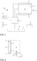
- FIG 6 A further display generated by the method according to the invention is shown on the display surface 2.
- a partial area 14 is reserved in each of the menu of the menu structure for the display of vehicle-type-specific information.
- this partial area 14 is placed freely on the display area 2 within the respective menu. However, it always has the same size, so that it can be easily recognized.
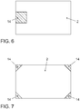
- the partial area 14 is reserved for the display of vehicle-type-specific information at the corners of each menu of the menu structure.
- the triangular partial areas 14 in the corners of the display area 2 can have a specific color which indicates the type of vehicle.
- partial area 14 is initially not displayed when a menu is displayed. If the user now enters the detection area 8 with a fingertip 12, for example, this is detected by the proximity detection device 7. This device 7 transmits a corresponding signal to the control device 3. The control device 3 interprets this signal as a user's intention to operate. The control device 3 then generates graphic data for a changed display of the menu.
- the partial area 14 is integrated in the display of the menu. At the in Figure 7 For example, colored corners appear. At the in Figure 6 The example shown is shown in a region of the display area 2, in which there is space in the corresponding menu, the partial area 14. In such a situation, the user normally looks at the display area 2 and therefore becomes aware of the vehicle-specific information.
- the partial area 14 is displayed on the display area 2. As soon as it has been detected that the fingertip 12 is no longer in the detection area 8, the partial area 14 is hidden, so that further space is made available on the display area 2 for the display of the current menu.
- partial area 14 is initially not shown in the menus. Even if the user enters the detection area 8 with an actuation object 12, the partial areas 14 are not displayed. However, if it has been detected that the actuation object 12, for example the user's fingertip, exits the detection area 8, the display area 2 becomes as above described for a certain time interval of 5 seconds, for example, is shown in the current menu.
- the partial surface 14 is, for example, in Figure 6 or Figure 7 shown always shown in the menus.
- the partial area 14 is shown changed.
- the color of the representation in the partial area 14 or the transparency of the representation can change.
- the partial area 14 can enlarge. If the operating object 12 emerges again from the detection area 8, this change is reversed again.
- the operating device 6 does not record any inputs within a certain time interval, the length of which is stored in the memory 11, the previous display disappears and a screen saver is displayed.
- This screen saver includes the display of vehicle-specific information. If it has been detected that an actuating object 12 enters the detection area 8, the screen saver disappears again and a menu appears in which the partial area 14 is shown, which represents the vehicle type-specific information in a different way.
- partial area 14 is displayed in all menus.
- the partial area 14 is only changed as described in the third exemplary embodiment when it has been detected that the actuating object 12 exits the detection area 8, specifically for a specific time interval of, for example, 5 seconds.
- partial area 14 is only displayed in certain menus of the hierarchical menu structure.
- the partial area 14 can only be displayed for menus which are as in Figure 4 shown have a control bar 13, or for menus as in Figure 5 shown have a status line 15.
- the partial surface 14 is designed as a switching element on which a symbol is shown as vehicle-type-specific information. If the user actuates the switching element of the partial area 14, for example by touching this switching element with his fingertip 12, the display on the display area 2, controlled by the control device 3, changes to a state in which the previous menu is no longer displayed and instead only vehicle-specific information is displayed. In this case, for example, a special logo or picture or a lettering can appear on the display surface 2. By pressing a further switching element or after a time interval has elapsed, this display can disappear again, so that the previous menu with the partial area 14 is displayed.
Landscapes
- Engineering & Computer Science (AREA)
- General Engineering & Computer Science (AREA)
- Theoretical Computer Science (AREA)
- Human Computer Interaction (AREA)
- Physics & Mathematics (AREA)
- General Physics & Mathematics (AREA)
- Chemical & Material Sciences (AREA)
- Combustion & Propulsion (AREA)
- Transportation (AREA)
- Mechanical Engineering (AREA)
- User Interface Of Digital Computer (AREA)
Applications Claiming Priority (2)
| Application Number | Priority Date | Filing Date | Title |
|---|---|---|---|
| DE102013008074.6A DE102013008074A1 (de) | 2013-05-10 | 2013-05-10 | Verfahren zum Steuern einer Anzeigefläche einer Bedienvorrichtung und Bedienvorrichtung in einem Fahrzeug |
| PCT/EP2014/058718 WO2014180715A1 (de) | 2013-05-10 | 2014-04-29 | Verfahren zum steuern einer anzeigefläche einer bedienvorrichtung und bedienvorrichtung in einem fahrzeug |
Publications (2)
| Publication Number | Publication Date |
|---|---|
| EP2994331A1 EP2994331A1 (de) | 2016-03-16 |
| EP2994331B1 true EP2994331B1 (de) | 2020-06-10 |
Family
ID=50639503
Family Applications (1)
| Application Number | Title | Priority Date | Filing Date |
|---|---|---|---|
| EP14721329.2A Active EP2994331B1 (de) | 2013-05-10 | 2014-04-29 | Verfahren zum steuern einer anzeigefläche einer bedienvorrichtung und bedienvorrichtung in einem fahrzeug |
Country Status (6)
| Country | Link |
|---|---|
| US (1) | US10235015B2 (ko) |
| EP (1) | EP2994331B1 (ko) |
| KR (1) | KR101797337B1 (ko) |
| CN (1) | CN105121211B (ko) |
| DE (1) | DE102013008074A1 (ko) |
| WO (1) | WO2014180715A1 (ko) |
Families Citing this family (3)
| Publication number | Priority date | Publication date | Assignee | Title |
|---|---|---|---|---|
| DE102013000880A1 (de) * | 2013-01-10 | 2014-07-10 | Volkswagen Aktiengesellschaft | Verfahren und Vorrichtung zu Bereitstellen einer Benutzerschnittstelle in einem Fahrzeug |
| DE102017113661B4 (de) * | 2017-06-21 | 2021-03-04 | Bcs Automotive Interface Solutions Gmbh | Kraftfahrzeugbedienvorrichtung |
| JP2022072294A (ja) * | 2020-10-29 | 2022-05-17 | 本田技研工業株式会社 | 表示装置及び車両 |
Family Cites Families (19)
| Publication number | Priority date | Publication date | Assignee | Title |
|---|---|---|---|---|
| DE19941956B4 (de) | 1999-09-03 | 2006-12-14 | Volkswagen Ag | Multifunktionsbedienelement mit einem Display |
| DE10037810A1 (de) * | 2000-08-03 | 2002-02-14 | Bosch Gmbh Robert | Elektrisches Gerät |
| DE102004033275A1 (de) * | 2004-07-09 | 2006-02-02 | Daimlerchrysler Ag | Freigabevorrichtung und Verfahren zum Freigeben oder Sperren einzelner vorbestimmter Funktionen eines Gerätes |
| DE102004045885A1 (de) * | 2004-09-22 | 2006-03-23 | Volkswagen Ag | Bedienelement für ein Kraftfahrzeug |
| KR20060053436A (ko) | 2004-11-15 | 2006-05-22 | 엘지전자 주식회사 | 디지털 방송수신기의 디스플레이 정보 제공방법 |
| DE102006032118B4 (de) * | 2006-07-12 | 2022-03-03 | Volkswagen Ag | Kombiinstrument für ein Kraftfahrzeug und Kraftfahrzeug |
| DE102007023290A1 (de) * | 2007-05-16 | 2008-11-20 | Volkswagen Ag | Multifunktionsanzeige- und Bedienvorrichtung und Verfahren zum Betreiben einer Multifunktionsanzeige- und Bedienvorrichtung mit verbesserter Auswahlbedienung |
| DE102007039442A1 (de) * | 2007-08-21 | 2009-02-26 | Volkswagen Ag | Verfahren zum Anzeigen von Informationen in einem Fahrzeug und Anzeigeeinrichtung für ein Fahrzeug |
| DE102007039444A1 (de) | 2007-08-21 | 2009-02-26 | Volkswagen Ag | Verfahren zum Anzeigen von Informationen in einem Kraftfahrzeug und Anzeigeeinrichtung für ein Kraftfahrzeug |
| DE102007054239B4 (de) * | 2007-11-12 | 2021-11-18 | Volkswagen Ag | Multifunktionsanzeige- und Bediensystem sowie Verfahren zum Bedienen von Funktionen und/oder Fahrzeugsystemen eines Kraftfahrzeugs mit einer verbesserten Bedienbarkeit mindestens eines Fahrzeugsystems oder einer Fahrzeugfunktion |
| GB2459689B (en) | 2008-05-01 | 2012-12-26 | Jaguar Cars | A method for providing information to a user of a motor vehicle |
| DE102008026488A1 (de) * | 2008-06-03 | 2009-12-24 | Continental Automotive Gmbh | Detektionssystem zur Annäherungserkennung |
| DE102009019561A1 (de) * | 2009-04-30 | 2010-11-04 | Volkswagen Ag | Verfahren zum Anzeigen von Informationen in einem Kraftfahrzeug und Anzeigeeinrichtung |
| DE102009036369A1 (de) * | 2009-08-06 | 2011-02-10 | Volkswagen Ag | Verfahren zum Betreiben einer Bedienvorrichtung und Bedienvorrichtung in einem Fahrzeug |
| DE102009051202A1 (de) * | 2009-10-29 | 2011-05-12 | Volkswagen Ag | Verfahren zum Betreiben einer Bedienvorrichtung und Bedienvorrichtung |
| DE102010032221A1 (de) * | 2010-07-26 | 2012-01-26 | Continental Automotive Gmbh | Manuell steuerbare elektronische Anzeigevorrichtung |
| DE102010034541A1 (de) * | 2010-08-17 | 2012-02-23 | Volkswagen Ag | Verfahren und Vorrichtung zum Bereitstellen einer Benutzerschnittstelle |
| DE102010055795A1 (de) * | 2010-12-23 | 2012-06-28 | Continental Automotive Gmbh | Verfahren zur Ausgabe von Informationen |
| DE102011116120A1 (de) | 2011-10-15 | 2013-04-18 | Volkswagen Aktiengesellschaft | Verfahren zum Bereitstellen einer Bedienvorrichtung in einem Fahrzeug und Bedienvorrichtung für ein Fahrzeug |
-
2013
- 2013-05-10 DE DE102013008074.6A patent/DE102013008074A1/de not_active Withdrawn
-
2014
- 2014-04-29 WO PCT/EP2014/058718 patent/WO2014180715A1/de active Application Filing
- 2014-04-29 KR KR1020157034875A patent/KR101797337B1/ko active IP Right Grant
- 2014-04-29 EP EP14721329.2A patent/EP2994331B1/de active Active
- 2014-04-29 US US14/889,721 patent/US10235015B2/en active Active
- 2014-04-29 CN CN201480022135.6A patent/CN105121211B/zh active Active
Non-Patent Citations (1)
| Title |
|---|
| None * |
Also Published As
| Publication number | Publication date |
|---|---|
| WO2014180715A1 (de) | 2014-11-13 |
| EP2994331A1 (de) | 2016-03-16 |
| US20160110033A1 (en) | 2016-04-21 |
| DE102013008074A1 (de) | 2014-11-13 |
| CN105121211A (zh) | 2015-12-02 |
| US10235015B2 (en) | 2019-03-19 |
| CN105121211B (zh) | 2019-02-22 |
| KR101797337B1 (ko) | 2017-11-13 |
| KR20160007582A (ko) | 2016-01-20 |
Similar Documents
| Publication | Publication Date | Title |
|---|---|---|
| EP3036126B1 (de) | Bedienverfahren für eine bedien- und anzeigevorrichtung in einem fahrzeug und bedien- und anzeigevorrichtung in einem fahrzeug | |
| EP2424743B1 (de) | Verfahren zum anzeigen und eingeben von informationen in einem kraftfahrzeug und anzeigeeinrichtung | |
| EP2885142B1 (de) | Bedienvorrichtung zum einstellen einer klimatisierungsvorrichtung eines fahrzeugs und verfahren hierzu | |
| EP2608185B1 (de) | Verfahren und Vorrichtung zum Bereitstellen einer Einparkhilfe in einem Fahrzeug | |
| EP2766211B1 (de) | Verfahren zum bereitstellen einer bedienvorrichtung, insbesondere in einem fahrzeug, und bedienvorrichtung für ein fahrzeug | |
| WO2005101092A1 (de) | Signalisiervorrichtung zur anzeige von warn- und/oder informationshinweisen in fahrzeugen | |
| DE102009051202A1 (de) | Verfahren zum Betreiben einer Bedienvorrichtung und Bedienvorrichtung | |
| EP3270278B1 (de) | Verfahren zum betreiben eines bediensystems und bediensystem | |
| EP3114554A1 (de) | Verfahren und vorrichtung zum bereitstellen einer graphischen benutzerschnittstelle in einem fahrzeug | |
| EP2994331B1 (de) | Verfahren zum steuern einer anzeigefläche einer bedienvorrichtung und bedienvorrichtung in einem fahrzeug | |
| EP2930603A1 (de) | Verfahren und Vorrichtung zum Bereitstellen einer graphischen Benutzerschnittstelle in einem Fahrzeug | |
| DE102020210650A1 (de) | Multi-kamera-sichtsysteme für ein arbeitsfahrzeug | |
| DE102009039114B4 (de) | Bedienvorrichtung für ein Fahrzeug | |
| DE102013204242A1 (de) | Anzeige- und Bedienvorrichtung für ein Kraftfahrzeug, Kraftfahrzeug und entsprechendes Verfahren | |
| EP2917062B1 (de) | Verfahren zum anzeigen von informationen in einem fahrzeug und vorrichtung zum steuern der anzeige | |
| DE102010052291B4 (de) | Verfahren und Vorrichtung zum Anzeigen von Informationen in einem Fahrzeug | |
| EP2809541B1 (de) | Verfahren zum bereitstellen einer bedienvorrichtung in einem fahrzeug und bedienvorrichtung für ein fahrzeug | |
| DE102013223518A1 (de) | Anzeigevorrichtung und Verfahren zur Steuerung einer Anzeigevorrichtung | |
| WO2015172939A1 (de) | Bedienverfahren und bediensystem in einem fahrzeug | |
| DE102013000219A1 (de) | Verfahren und Vorrichtung zum Bedienen einer Einrichtung | |
| DE102012016110A1 (de) | Verfahren zum Bereitstellen einer Bedienvorrichtung in einem Fahrzeug und Bedienvorrichtung hierfür | |
| EP2885152B1 (de) | Verfahren zum anzeigen von informationen in einem fahrzeug und anzeigeeinrichtung dafür | |
| DE102015004367A1 (de) | Verfahren zum Steuern einer Funktion eines Kraftfahrzeugs | |
| EP3040836A1 (de) | Fortbewegungsmittel, Anwenderschnittstelle und Verfahren zur Reduzierung einer Lichtemission einer Anzeigeeinrichtung eines Fortbewegungsmittels | |
| DE102013215484A1 (de) | Anzeigesystem und Visualisierungsverfahren für ein Fahrzeug |
Legal Events
| Date | Code | Title | Description |
|---|---|---|---|
| PUAI | Public reference made under article 153(3) epc to a published international application that has entered the european phase |
Free format text: ORIGINAL CODE: 0009012 |
|
| 17P | Request for examination filed |
Effective date: 20151210 |
|
| AK | Designated contracting states |
Kind code of ref document: A1 Designated state(s): AL AT BE BG CH CY CZ DE DK EE ES FI FR GB GR HR HU IE IS IT LI LT LU LV MC MK MT NL NO PL PT RO RS SE SI SK SM TR |
|
| AX | Request for extension of the european patent |
Extension state: BA ME |
|
| DAX | Request for extension of the european patent (deleted) | ||
| STAA | Information on the status of an ep patent application or granted ep patent |
Free format text: STATUS: EXAMINATION IS IN PROGRESS |
|
| 17Q | First examination report despatched |
Effective date: 20191022 |
|
| GRAP | Despatch of communication of intention to grant a patent |
Free format text: ORIGINAL CODE: EPIDOSNIGR1 |
|
| STAA | Information on the status of an ep patent application or granted ep patent |
Free format text: STATUS: GRANT OF PATENT IS INTENDED |
|
| INTG | Intention to grant announced |
Effective date: 20200224 |
|
| GRAS | Grant fee paid |
Free format text: ORIGINAL CODE: EPIDOSNIGR3 |
|
| GRAA | (expected) grant |
Free format text: ORIGINAL CODE: 0009210 |
|
| STAA | Information on the status of an ep patent application or granted ep patent |
Free format text: STATUS: THE PATENT HAS BEEN GRANTED |
|
| AK | Designated contracting states |
Kind code of ref document: B1 Designated state(s): AL AT BE BG CH CY CZ DE DK EE ES FI FR GB GR HR HU IE IS IT LI LT LU LV MC MK MT NL NO PL PT RO RS SE SI SK SM TR |
|
| REG | Reference to a national code |
Ref country code: GB Ref legal event code: FG4D Free format text: NOT ENGLISH |
|
| REG | Reference to a national code |
Ref country code: AT Ref legal event code: REF Ref document number: 1278912 Country of ref document: AT Kind code of ref document: T Effective date: 20200615 Ref country code: CH Ref legal event code: EP |
|
| REG | Reference to a national code |
Ref country code: DE Ref legal event code: R096 Ref document number: 502014014284 Country of ref document: DE |
|
| REG | Reference to a national code |
Ref country code: IE Ref legal event code: FG4D Free format text: LANGUAGE OF EP DOCUMENT: GERMAN |
|
| REG | Reference to a national code |
Ref country code: LT Ref legal event code: MG4D |
|
| PG25 | Lapsed in a contracting state [announced via postgrant information from national office to epo] |
Ref country code: GR Free format text: LAPSE BECAUSE OF FAILURE TO SUBMIT A TRANSLATION OF THE DESCRIPTION OR TO PAY THE FEE WITHIN THE PRESCRIBED TIME-LIMIT Effective date: 20200911 Ref country code: FI Free format text: LAPSE BECAUSE OF FAILURE TO SUBMIT A TRANSLATION OF THE DESCRIPTION OR TO PAY THE FEE WITHIN THE PRESCRIBED TIME-LIMIT Effective date: 20200610 Ref country code: NO Free format text: LAPSE BECAUSE OF FAILURE TO SUBMIT A TRANSLATION OF THE DESCRIPTION OR TO PAY THE FEE WITHIN THE PRESCRIBED TIME-LIMIT Effective date: 20200910 Ref country code: SE Free format text: LAPSE BECAUSE OF FAILURE TO SUBMIT A TRANSLATION OF THE DESCRIPTION OR TO PAY THE FEE WITHIN THE PRESCRIBED TIME-LIMIT Effective date: 20200610 Ref country code: LT Free format text: LAPSE BECAUSE OF FAILURE TO SUBMIT A TRANSLATION OF THE DESCRIPTION OR TO PAY THE FEE WITHIN THE PRESCRIBED TIME-LIMIT Effective date: 20200610 |
|
| REG | Reference to a national code |
Ref country code: NL Ref legal event code: MP Effective date: 20200610 |
|
| PG25 | Lapsed in a contracting state [announced via postgrant information from national office to epo] |
Ref country code: BG Free format text: LAPSE BECAUSE OF FAILURE TO SUBMIT A TRANSLATION OF THE DESCRIPTION OR TO PAY THE FEE WITHIN THE PRESCRIBED TIME-LIMIT Effective date: 20200910 Ref country code: RS Free format text: LAPSE BECAUSE OF FAILURE TO SUBMIT A TRANSLATION OF THE DESCRIPTION OR TO PAY THE FEE WITHIN THE PRESCRIBED TIME-LIMIT Effective date: 20200610 Ref country code: LV Free format text: LAPSE BECAUSE OF FAILURE TO SUBMIT A TRANSLATION OF THE DESCRIPTION OR TO PAY THE FEE WITHIN THE PRESCRIBED TIME-LIMIT Effective date: 20200610 Ref country code: HR Free format text: LAPSE BECAUSE OF FAILURE TO SUBMIT A TRANSLATION OF THE DESCRIPTION OR TO PAY THE FEE WITHIN THE PRESCRIBED TIME-LIMIT Effective date: 20200610 |
|
| PG25 | Lapsed in a contracting state [announced via postgrant information from national office to epo] |
Ref country code: AL Free format text: LAPSE BECAUSE OF FAILURE TO SUBMIT A TRANSLATION OF THE DESCRIPTION OR TO PAY THE FEE WITHIN THE PRESCRIBED TIME-LIMIT Effective date: 20200610 Ref country code: NL Free format text: LAPSE BECAUSE OF FAILURE TO SUBMIT A TRANSLATION OF THE DESCRIPTION OR TO PAY THE FEE WITHIN THE PRESCRIBED TIME-LIMIT Effective date: 20200610 |
|
| PG25 | Lapsed in a contracting state [announced via postgrant information from national office to epo] |
Ref country code: PT Free format text: LAPSE BECAUSE OF FAILURE TO SUBMIT A TRANSLATION OF THE DESCRIPTION OR TO PAY THE FEE WITHIN THE PRESCRIBED TIME-LIMIT Effective date: 20201012 Ref country code: ES Free format text: LAPSE BECAUSE OF FAILURE TO SUBMIT A TRANSLATION OF THE DESCRIPTION OR TO PAY THE FEE WITHIN THE PRESCRIBED TIME-LIMIT Effective date: 20200610 Ref country code: EE Free format text: LAPSE BECAUSE OF FAILURE TO SUBMIT A TRANSLATION OF THE DESCRIPTION OR TO PAY THE FEE WITHIN THE PRESCRIBED TIME-LIMIT Effective date: 20200610 Ref country code: SM Free format text: LAPSE BECAUSE OF FAILURE TO SUBMIT A TRANSLATION OF THE DESCRIPTION OR TO PAY THE FEE WITHIN THE PRESCRIBED TIME-LIMIT Effective date: 20200610 Ref country code: IT Free format text: LAPSE BECAUSE OF FAILURE TO SUBMIT A TRANSLATION OF THE DESCRIPTION OR TO PAY THE FEE WITHIN THE PRESCRIBED TIME-LIMIT Effective date: 20200610 Ref country code: RO Free format text: LAPSE BECAUSE OF FAILURE TO SUBMIT A TRANSLATION OF THE DESCRIPTION OR TO PAY THE FEE WITHIN THE PRESCRIBED TIME-LIMIT Effective date: 20200610 Ref country code: CZ Free format text: LAPSE BECAUSE OF FAILURE TO SUBMIT A TRANSLATION OF THE DESCRIPTION OR TO PAY THE FEE WITHIN THE PRESCRIBED TIME-LIMIT Effective date: 20200610 |
|
| PG25 | Lapsed in a contracting state [announced via postgrant information from national office to epo] |
Ref country code: IS Free format text: LAPSE BECAUSE OF FAILURE TO SUBMIT A TRANSLATION OF THE DESCRIPTION OR TO PAY THE FEE WITHIN THE PRESCRIBED TIME-LIMIT Effective date: 20201010 Ref country code: SK Free format text: LAPSE BECAUSE OF FAILURE TO SUBMIT A TRANSLATION OF THE DESCRIPTION OR TO PAY THE FEE WITHIN THE PRESCRIBED TIME-LIMIT Effective date: 20200610 Ref country code: PL Free format text: LAPSE BECAUSE OF FAILURE TO SUBMIT A TRANSLATION OF THE DESCRIPTION OR TO PAY THE FEE WITHIN THE PRESCRIBED TIME-LIMIT Effective date: 20200610 |
|
| REG | Reference to a national code |
Ref country code: DE Ref legal event code: R097 Ref document number: 502014014284 Country of ref document: DE |
|
| PLBE | No opposition filed within time limit |
Free format text: ORIGINAL CODE: 0009261 |
|
| STAA | Information on the status of an ep patent application or granted ep patent |
Free format text: STATUS: NO OPPOSITION FILED WITHIN TIME LIMIT |
|
| PG25 | Lapsed in a contracting state [announced via postgrant information from national office to epo] |
Ref country code: DK Free format text: LAPSE BECAUSE OF FAILURE TO SUBMIT A TRANSLATION OF THE DESCRIPTION OR TO PAY THE FEE WITHIN THE PRESCRIBED TIME-LIMIT Effective date: 20200610 |
|
| 26N | No opposition filed |
Effective date: 20210311 |
|
| PG25 | Lapsed in a contracting state [announced via postgrant information from national office to epo] |
Ref country code: SI Free format text: LAPSE BECAUSE OF FAILURE TO SUBMIT A TRANSLATION OF THE DESCRIPTION OR TO PAY THE FEE WITHIN THE PRESCRIBED TIME-LIMIT Effective date: 20200610 |
|
| PG25 | Lapsed in a contracting state [announced via postgrant information from national office to epo] |
Ref country code: MC Free format text: LAPSE BECAUSE OF FAILURE TO SUBMIT A TRANSLATION OF THE DESCRIPTION OR TO PAY THE FEE WITHIN THE PRESCRIBED TIME-LIMIT Effective date: 20200610 |
|
| PG25 | Lapsed in a contracting state [announced via postgrant information from national office to epo] |
Ref country code: LU Free format text: LAPSE BECAUSE OF NON-PAYMENT OF DUE FEES Effective date: 20210429 |
|
| REG | Reference to a national code |
Ref country code: BE Ref legal event code: MM Effective date: 20210430 |
|
| PG25 | Lapsed in a contracting state [announced via postgrant information from national office to epo] |
Ref country code: LI Free format text: LAPSE BECAUSE OF NON-PAYMENT OF DUE FEES Effective date: 20210430 Ref country code: CH Free format text: LAPSE BECAUSE OF NON-PAYMENT OF DUE FEES Effective date: 20210430 |
|
| PG25 | Lapsed in a contracting state [announced via postgrant information from national office to epo] |
Ref country code: IE Free format text: LAPSE BECAUSE OF NON-PAYMENT OF DUE FEES Effective date: 20210429 |
|
| PG25 | Lapsed in a contracting state [announced via postgrant information from national office to epo] |
Ref country code: IS Free format text: LAPSE BECAUSE OF FAILURE TO SUBMIT A TRANSLATION OF THE DESCRIPTION OR TO PAY THE FEE WITHIN THE PRESCRIBED TIME-LIMIT Effective date: 20201010 |
|
| REG | Reference to a national code |
Ref country code: AT Ref legal event code: MM01 Ref document number: 1278912 Country of ref document: AT Kind code of ref document: T Effective date: 20210429 |
|
| PG25 | Lapsed in a contracting state [announced via postgrant information from national office to epo] |
Ref country code: BE Free format text: LAPSE BECAUSE OF NON-PAYMENT OF DUE FEES Effective date: 20210430 |
|
| PG25 | Lapsed in a contracting state [announced via postgrant information from national office to epo] |
Ref country code: AT Free format text: LAPSE BECAUSE OF NON-PAYMENT OF DUE FEES Effective date: 20210429 |
|
| PG25 | Lapsed in a contracting state [announced via postgrant information from national office to epo] |
Ref country code: HU Free format text: LAPSE BECAUSE OF FAILURE TO SUBMIT A TRANSLATION OF THE DESCRIPTION OR TO PAY THE FEE WITHIN THE PRESCRIBED TIME-LIMIT; INVALID AB INITIO Effective date: 20140429 |
|
| P01 | Opt-out of the competence of the unified patent court (upc) registered |
Effective date: 20230523 |
|
| PG25 | Lapsed in a contracting state [announced via postgrant information from national office to epo] |
Ref country code: CY Free format text: LAPSE BECAUSE OF FAILURE TO SUBMIT A TRANSLATION OF THE DESCRIPTION OR TO PAY THE FEE WITHIN THE PRESCRIBED TIME-LIMIT Effective date: 20200610 |
|
| PGFP | Annual fee paid to national office [announced via postgrant information from national office to epo] |
Ref country code: FR Payment date: 20230421 Year of fee payment: 10 Ref country code: DE Payment date: 20230430 Year of fee payment: 10 |
|
| PGFP | Annual fee paid to national office [announced via postgrant information from national office to epo] |
Ref country code: GB Payment date: 20230418 Year of fee payment: 10 |
|
| REG | Reference to a national code |
Ref country code: DE Ref legal event code: R079 Ref document number: 502014014284 Country of ref document: DE Free format text: PREVIOUS MAIN CLASS: B60K0037060000 Ipc: B60K0035100000 |
|
| PG25 | Lapsed in a contracting state [announced via postgrant information from national office to epo] |
Ref country code: MK Free format text: LAPSE BECAUSE OF FAILURE TO SUBMIT A TRANSLATION OF THE DESCRIPTION OR TO PAY THE FEE WITHIN THE PRESCRIBED TIME-LIMIT Effective date: 20200610 |