EP2994076B1 - Skoliosestütze - Google Patents
Skoliosestütze Download PDFInfo
- Publication number
- EP2994076B1 EP2994076B1 EP14794645.3A EP14794645A EP2994076B1 EP 2994076 B1 EP2994076 B1 EP 2994076B1 EP 14794645 A EP14794645 A EP 14794645A EP 2994076 B1 EP2994076 B1 EP 2994076B1
- Authority
- EP
- European Patent Office
- Prior art keywords
- brace
- pad
- wearer
- belt
- vertical strut
- Prior art date
- Legal status (The legal status is an assumption and is not a legal conclusion. Google has not performed a legal analysis and makes no representation as to the accuracy of the status listed.)
- Active
Links
Images


Classifications
-
- A—HUMAN NECESSITIES
- A61—MEDICAL OR VETERINARY SCIENCE; HYGIENE
- A61F—FILTERS IMPLANTABLE INTO BLOOD VESSELS; PROSTHESES; DEVICES PROVIDING PATENCY TO, OR PREVENTING COLLAPSING OF, TUBULAR STRUCTURES OF THE BODY, e.g. STENTS; ORTHOPAEDIC, NURSING OR CONTRACEPTIVE DEVICES; FOMENTATION; TREATMENT OR PROTECTION OF EYES OR EARS; BANDAGES, DRESSINGS OR ABSORBENT PADS; FIRST-AID KITS
- A61F5/00—Orthopaedic methods or devices for non-surgical treatment of bones or joints; Nursing devices ; Anti-rape devices
- A61F5/01—Orthopaedic devices, e.g. long-term immobilising or pressure directing devices for treating broken or deformed bones such as splints, casts or braces
- A61F5/03—Corsets or bandages for abdomen, teat or breast support, with or without pads
-
- A—HUMAN NECESSITIES
- A61—MEDICAL OR VETERINARY SCIENCE; HYGIENE
- A61F—FILTERS IMPLANTABLE INTO BLOOD VESSELS; PROSTHESES; DEVICES PROVIDING PATENCY TO, OR PREVENTING COLLAPSING OF, TUBULAR STRUCTURES OF THE BODY, e.g. STENTS; ORTHOPAEDIC, NURSING OR CONTRACEPTIVE DEVICES; FOMENTATION; TREATMENT OR PROTECTION OF EYES OR EARS; BANDAGES, DRESSINGS OR ABSORBENT PADS; FIRST-AID KITS
- A61F5/00—Orthopaedic methods or devices for non-surgical treatment of bones or joints; Nursing devices ; Anti-rape devices
- A61F5/01—Orthopaedic devices, e.g. long-term immobilising or pressure directing devices for treating broken or deformed bones such as splints, casts or braces
- A61F5/02—Orthopaedic corsets
- A61F5/028—Braces for providing support to the lower back, e.g. lumbo sacral supports
-
- A—HUMAN NECESSITIES
- A61—MEDICAL OR VETERINARY SCIENCE; HYGIENE
- A61F—FILTERS IMPLANTABLE INTO BLOOD VESSELS; PROSTHESES; DEVICES PROVIDING PATENCY TO, OR PREVENTING COLLAPSING OF, TUBULAR STRUCTURES OF THE BODY, e.g. STENTS; ORTHOPAEDIC, NURSING OR CONTRACEPTIVE DEVICES; FOMENTATION; TREATMENT OR PROTECTION OF EYES OR EARS; BANDAGES, DRESSINGS OR ABSORBENT PADS; FIRST-AID KITS
- A61F5/00—Orthopaedic methods or devices for non-surgical treatment of bones or joints; Nursing devices ; Anti-rape devices
- A61F5/01—Orthopaedic devices, e.g. long-term immobilising or pressure directing devices for treating broken or deformed bones such as splints, casts or braces
- A61F5/02—Orthopaedic corsets
- A61F5/024—Orthopaedic corsets having pressure pads connected in a frame for reduction or correction of the curvature of the spine
Definitions
- the field of the invention is orthotics.
- Scoliosis is a medical condition associated with an abnormally curved spine, often thought to be a progressive disease, at least until adulthood. Scoliosis can have severe adverse affects on a patient's life, both physically and physiologically.
- One possible method of treating or managing scoliosis is surgery. Unfortunately, scoliosis surgery can be very risky. Less invasive methods of treating or managing scoliosis has traditionally included physical therapy, chiropractic therapy, or bracing, among other things.
- the present disclosure provides apparatus, systems and methods in which a scoliosis brace is configured to provide adjustable support to a wearer.
- the brace preferably comprises a flexible belt configured to wrap entirely around a mid-portion of a wearer, along with various components (e.g., struts, pads, adjustment mechanisms, etc.) configured to removably couple with the flexible belt and thereby provide customizable support to different portions of a wearer's body.
- various components e.g., struts, pads, adjustment mechanisms, etc.
- a brace of the inventive subject matter can advantageously be configured to add a force or restrict motion in the sagittal, transverse and coronal planes.
- the belt applies loading from the brace to an anterior, middle portion of the wearer.
- a scoliosis brace comprises a first vertical strut having an anchor pad (or base pad), and that is removably coupled to the belt, preferably on the belt's interior side ( i.e. , the side facing toward the wearer). It is contemplated that the anchor pad or the strut can removably attach to the belt in any commercially suitable manner, including for example, via a hook and loop fastener, snaps, buttons, magnets, and threading.
- the brace could include one or more vertical struts depending on the wearer's needs. Each of the struts could include one or more pieces without departing from the scope of the invention described herein.
- the first strut could comprise two struts that are coupled together to form a single strut, or could instead comprise a unitary structure.
- a “vertical strut” is defined broadly to include a plurality of components (pads, struts, angle or height adjustment mechanisms, etc.) that are coupled with one another to create a single piece.
- a “strut” is a single rod or bar forming a part of a framework. It can generally be preferred that a strut is made from either (1) a rigid material (e.g., a metal, a hard plastic, etc.) that requires more than an average person's force to bend, or (2) a material (e.g., aluminum, etc.) that is sized and dimensioned to be pliable when a strong force is applied, but sturdy when an ordinary force is applied.
- a rigid material e.g., a metal, a hard plastic, etc.
- a material e.g., aluminum, etc.
- the first strut can include a thoracic pad at a first end portion such that the thoracic pad can provide a pressure to a first side of the wearer below the underarm. It is contemplated that the first strut can be composed of one or more pieces and could be configured to allow for adjustment of a height of the first strut to increase a distance between the belt and the thoracic pad. Where the first strut comprises two or more pieces, it is contemplated that the pieces could be movably coupled to one another such that one can rotate or pivot relative to the other.
- a distance of the thoracic pad relative to the central point of the anchor pad can be adjusted via any commercially suitable height adjustment mechanism, including for example, a rack and pinion mechanism, a biasing mechanism, a slidably coupled telescoped component, or any other commercially suitable component. Similar mechanisms can also be provided to adjust a horizontal position of the thoracic pad relative to the central point of the anchor pad.
- a brace of the present disclosure can also comprise a first hip pad coupled to the first strut, and configured to provide support to a hip area of a wearer.
- the first strut could include a height adjustment mechanism (e.g., to adjust a distance of the hip pad relative to the belt or an angle adjustment mechanism (e.g., to adjust a horizontal or vertical position of the hip pad on the wearer relative to the belt).
- the thoracic pad can be coupled to a curved arm configured to at least partially wrap around an upper chest portion of a wearer.
- the curved arm is preferably coupled to a de-rotation pad that is configured to put pressure on the upper chest wall on one side to cause a force intended to resist forward motion and rotation of that side of the chest when the brace is worn.
- One or more straps can be provided and configured to couple with two or more components of the brace.
- a first strap can be coupled to the belt (e.g., via hook and loop fastener, snaps, buttons, threading, zipper, or other commercially suitable fastener(s) or combinations thereof) and the thoracic pad (e.g., via a carabiner, a buckle, a button, a snap, or other commercially suitable fastener(s) or combinations thereof).
- a second strap can be configured to couple to at least two of the following, among other components: the de-rotation pad, the rounded arm, the first strut, the anchor pad, or the hip pad.
- a first vertical strut comprising the anchor pad, first strut, thoracic pad, de-rotation pad or hip pad can be coupled to the belt such that it provides support predominantly to a left or right side of the wearer.
- the term "provides support predominantly to a left or right side” means that at least 80% of the components are located on a single side of the wearer.
- the first vertical strut can be coupled to the belt such that the belt supports the first vertical strut, while the strut provides support predominantly to a left side of the wearer, even though 20% or less of the support is provided to the right side of the wearer.
- At least 90%, at least 95%, or even 100% of the support can be provided to a single side of the wearer via the first vertical strut. It is contemplated that a second vertical strut having one or more components can be provided, if needed, that is coupled to the belt such that the second vertical strut is disposed, and thereby provides support predominantly to, the opposite side of the wearer.
- the additional components can include, for example a second anchor pad, a second thoracic pad, and/or, a second hip pad.
- the additional components could further include a second de-rotation pad coupled to the second thoracic pad via a second rounded arm and/or any other suitable component(s).
- each of the struts, straps, and pads can be removably coupled with, or attached to, another strut, pad, belt or other component of the inventive subject matter.
- a strut, pad or other component is moved from a first location to a second location, it is contemplated that the locations can be completely distinct or partially overlapping.
- a strut, pad or other component can be moved by as little as 5 cm, 2 cm, or even 1 cm or less, or can be moved by as much as 6 cm, 10 cm, or even 20 cm or even more.
- each embodiment represents a single combination of inventive elements, the disclosure is considered to include all possible combinations of the disclosed elements. Thus if one embodiment comprises elements A, B, and C, and a second embodiment comprises elements B and D, then the disclosure is also considered to include other remaining combinations of A, B, C, or D, even if not explicitly disclosed.
- a brace of the inventive subject matter can utilize one or more of the components discussed in co-owned U.S. Patent Nos. 7,001,348 and 8,142,377 , and U.S. Patent Application Publication Nos. 2012/0232450 and 2012/0245502 .
- a brace can utilize a pulley system as disclosed in U.S. Patent No. 7,001,348 .
- FIG. 1 shows a vertical strut 100 of the inventive subject matter.
- Vertical strut 100 is configured to provide support to a right or left side of a wearer, and preferably comprises an anchor pad 170 coupled with strut 190, a hip pad 180, and a thoracic pad 140. It is contemplated that the a rounded arm 130 and a de-rotation pad 120 having a buckle receiver 110 can be coupled to the vertical strut depending on the needs of the wearer.
- Anchor pad 170 comprises a hook or loop fastener 171 that is configured to removably attach to a belt (not shown).
- Contemplated pads can comprise any commercially suitable material(s), including for example, foam, silicon, nylon, cotton, mesh, or any other suitable material.
- strut 190 can be coupled to angle/height adjustment mechanism 150 that allows a user to adjust a horizontal or vertical location (i.e., a distance) of thoracic pad 140 relative to the anchor pad 170.
- angle/height adjustment mechanism is a second piece 162 that couples to the strut 190 via a screw mechanism 161.
- the horizontal location of thoracic pad 140 relative to anchor pad 170 can be adjusted via adjustment mechanism 150 by simply rotating the second piece 162 relative to the first strut 190.
- the vertical height of thoracic pad 140 relative to anchor pad 170 can be adjusted via adjustment mechanism 150 by unscrewing screw 161, adjusting the alignment of perforations on the first strut 190 and second piece 162, and re-tightening screw 161.
- First strut can thereby apply pressure above and below a wearer's mid-line via the upper thoracic pad 140 and lower hip pad 180, each of which is coupled to the first strut 190.
- the belt applies loading to each end of the first strut 190 and second piece 162 where used.
- the first strut 190 can be supported by the belt, such that the vertical strut 100 and brace is dependent on the belt.
- the belt can include a pad disposed at the wearer's pubic region such that the pad counteracts the forces applied to the left and/or right side of the wearer.
- angle or height adjustment mechanisms can be used, including for example, a series of snaps, a rack and pinion mechanism, a biasing mechanism, a slidably coupled telescoped component, or any other commercially suitable mechanisms.
- a curved arm 130 can be coupled to second piece 162 or first strut 190 preferably via an angle/height adjustment mechanism 160.
- Curved arm 130 is coupled with de-rotation pad 120, which advantageously provides support to an upper chest region of a wearer, and is configured to at least partially prevent a rotation of a patient's torso when worn, for example, by preventing a rotation of one or more components of the brace with respect to another component.
- FIG. 2 is a close up view of a thoracic pad 260, curved arm 215 and de-rotation pad 210 of a vertical strut 200 of the inventive subject matter.
- Strut 280 is coupled to thoracic pad 260 via a fastener that can also act as a height adjustment mechanism 270.
- strut 280 could lack a height adjustment mechanism.
- Thoracic pad 260 is further coupled to curved arm 215, which can also act as a part of height and angle adjustment mechanism 240 in conjunction with one or more fasteners 216.
- a user can remove or loosen fasteners 216 and realign the perforations of curved arm 215 with a suitable perforation of thoracic pad 260 in order to adjust an angle or height of de-rotation pad 210 relative to thoracic pad 260.
- thoracic pad 260 is shown including a metal structure that holds padding in place, it is contemplated that the structure and thoracic pad could be distinct pieces coupled together to form thoracic pad 260.
- De-rotation pad 210 can be coupled to curved arm 215 in any commercially suitable manner. However, it is currently preferred that de-rotation pad 210 and curved arm 215 are coupled together via a series of perforations and a snap configured to lock de-rotation pad 210 in a position aligned with one of the perforations.
- De-rotation pad 210's fastener (height adjustment mechanism 220) is coupled to buckle receiver 250, which is configured to receive a buckle of a strap (not shown).
- a strap can be advantageously used to block a rotation of a component of the brace with respect to another component of the brace or providing a tension or tautness between the components to which it is attached.
- a strap that is coupled to buckle receiver 250 and the belt can advantageously be used to block a change in a vertical position of a de-rotation pad relative to the belt, and further block a rotation of the vertical strut 200 comprising the de-rotation pad relative to the belt (alternatively or additionally to the blocking provided by a fastening mechanism between the belt and vertical strut).
- FIG. 3 shows another embodiment of a vertical strut 300 of the inventive subject matter.
- Vertical strut 300 comprises an anchor pad 310, thoracic pad 320 and an optional adjustment mechanism 325 that allows for angular and height adjustment of the thoracic pad 320 relative to the anchor pad 310.
- the vertical strut can include first and second struts 316 and 317, respectively, although a single strut could alternatively be used.
- vertical strut 300 could also include additional components that are removable and adjustable with respect to the anchor pad 310 and thoracic pad 320.
- vertical strut 300 could comprise a third strut coupled with a hip pad that extends below the anchor pad 310 in a direction opposite that of the thoracic pad.
- the hip pad could be coupled to a single strut that extends above and below the anchor pad..
- vertical strut 100 or 200 could be worn on a right side of a wearer while vertical strut 300 is worn on a left side of a wearer, or vice versa.
- loading can be applied to the left and right side of the wearer simultaneously by coupling a vertical strut to the belt such that each strut aligns with an opposing side of the wearer.
- Figure 4 shows a first vertical strut 440 and second vertical strut 460 each removably coupled to a belt 410 that wraps around a mid-line of wearer.
- Belt 410 includes hook or loop fastener 420 on an inner side 422, and a complementary hook or loop fastener 430 on an outer side 425, which allows the belt to fasten to itself in some embodiments.
- any commercially suitable fastener(s) could be used to couple the belt 410 to the wearer.
- the coupling of the invention is defined in claim 1 only.
- Brace 400 also comprises a first vertical strut 440 removably attached to a left side of belt 400, and a second vertical strut 460 removably attached to a right side of belt 400.
- each of the first and second vertical struts is coupled to an inner side of the belt - i.e., the surface of the belt facing toward the wearer when worn.
- Belt 410 is preferably configured to wrap entirely around a mid-portion of a wearer and securely fasten to itself via hook or loop fasteners 420 and 430, although any commercially suitable fasteners could be used.
- the fasteners of the invention are defined in claim 1 only.
- belt 410 can be used to support one or more vertical struts coupled to the belt.
- the vertical struts can be coupled solely to the belt and thereby entirely supported by the belt 410 disposed about a mid-portion of the wearer.
- brace 400 can include a first strap 470 coupled to the belt 410 at a first attachment point (on outer side 425), and configured to couple with a thoracic pad of second vertical strut 460, and de-rotation pad 450 of first vertical strut 440 via buckle receiver 455.
- First strap 470 and de-rotation pad 450 can be advantageously used together to cause an increase in pressure on a portion of the patient to support them in a desired position.
- references to a "fastener” are used broadly to refer to any commercially suitable fastener(s), including for example, a hook and loop fastener, a button, a snap, a belt type buckle, a side squeeze buckle, a magnet, a zipper, perforations and screws or snaps, or any other commercially suitable fastener(s).
- a fastener can also serve as, or be coupled with, an adjustment mechanism such as a length, height, angle or other adjustment mechanism.
- Figure 5 shows the brace 400 of Figure 4 as partially fastened to a wearer.
- belt 410 is fastened to itself around the mid-portion of the wearer via hook and loop fasteners, and the brace 400 can being tightened via a first cord system 475 and a second cord system 476, although a single cord system could be used.
- the pull tabs of cord systems 475 and 476 e.g., 475A and 476A
- a brace of the inventive subject matter can utilize one or more of the components discussed in co-owned U.S. Patent Nos.
- a brace can utilize a pulley system as disclosed in U.S. Patent No. 7,001,348 .
- Brace 400 can optionally comprise a second strap 478, which is fastened to an outer side of belt 400 via any suitable fastener (e.g., hook or loop, snaps, buttons, etc.) and further coupled to a thoracic pad of first vertical strut 440.
- any suitable fastener e.g., hook or loop, snaps, buttons, etc.
- Figure 6 shows a front-left side view of the brace 400 of Figures 4 and 5 .
- First strap 470 is attached to belt 410 and second vertical strut 460, and is shown in being fastened to buckle receiver 455 of de-rotation pad 450 via buckle 471 of first strap 470.
- Second strap 478 is removably fastened to belt 410 and removably fastened to the thoracic pad of first vertical strut 440 via a screw that also acts as part of an angle and height adjustment mechanism between the curved arm and thoracic pad of first vertical strut 440.
- FIG 7 shows a back view of the brace 400 shown in Figure 4 as worn by a wearer.
- Brace 400 comprises a tightening mechanism 480 shown in having two cord systems 475 and 476.
- first cord system 475 can be configured to tighten a top portion of belt 410 (e.g., shorten a distance between the top portion of right cord guide cover 482 and left cord guide cover 484) when pulled in a first direction
- second cord system 476 can be configured to tighten a bottom portion of belt 410 (e.g., shorten a distance between the bottom portion of right cord guide cover 482 and left cord guide cover 484) when pulled in a second direction different from the first direction.
- each cord could be used to tighten a top and a bottom portion of belt 410.
- Brace 400 further comprises a third strap 486 and fourth strap 488.
- Third strap 486 is configured to attach to left cord guide cover 484 and first vertical strut 440 via any suitable fastening means
- fourth strap 488 is configured to attach to right cord guide cover 482 and second vertical strut 460 via any suitable fastening means.
- first, second, third and fourth straps (470, 478, 486, and 488) can be used together to provide increased support to a wearer while ensuring that a proper amount of force is being applied to the areas intended.
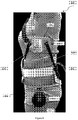
- Figure 8 is a left side view of the brace 400 of Figures 4-7 showing first vertical strut 440 coupled to an inner side of belt 410 that extends about a mid-portion of the wearer.
- anchor pad 441 is substantially aligned with the mid-portion of the wearer.
- Vertical strut 440 is configured to provide pressure to at least two portions of the wearer's body (e.g., upper and lower portions).
- the first area 440A (upper portion) is the left side of the wearer between the underarm and mid-portion, which is supported by thoracic pad 442.
- the second area 440B (lower portion) is the left hip of the wearer, which is supported by hip pad 443.
- the vertical strut 440 is dependent on and supported by the belt 410, and loading is applied to the upper and lower portions of the wearer's body.
- second strap 478 and third strap 486 can be fastened to belt 410 and thoracic pad 442, and are configured to provide an adjustable amount of tension or tautness between the two components to which they are attached, or prevent a rotation of one component (e.g., the thoracic pad 442) relative to another component (e.g., the midline of the belt where the belt could be folded in half along its length) to thereby prevent a rotation of a patient's body, or adjust the patient's body back into a less rotated state.
- one component e.g., the thoracic pad 442
- another component e.g., the midline of the belt where the belt could be folded in half along its length
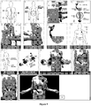
- Figure 9 provides a step by step flowchart of one method of fitting a wearer with a brace.
- step 1 a healthcare professional or other person can obtain an x-ray of a wearer's spine to identify a curve apex and locations where force should be applied. For example, step 1 shows that force should be applied at points A, B and C.
- Step 2 shows how to locate an anchor point to which the anchor pad can be aligned (i.e., a mid-portion of the wearer).
- the left anchor point for example, is located between the rib cage and iliac crest of the wearer.
- the anchor point(s) can alternatively be in a location other than between the rib cage and iliac crest.
- Step 3 shows a vertical strut being fit on a wearer based on the anchor pad's alignment with the left anchor point.
- the remaining components of the vertical strut can be adjusted (e.g., bending of the strut, adjustment of the relative heights of each component, adjustment of an angle between components, etc.) to provided a force to the intended areas of a user (e.g., areas A and C of step 1) as shown in Steps 4 and 5.
- Step 4 shows a possible arrangement of components of a vertical strut, although some of the components may not be used.
- Step 5 shows that the thoracic pad of the first vertical strut can align with force point A.
- a Phillips screw driver can be used to align the thoracic and hip pads with previously identified locations where force will be applied.
- Step 6 shows a second vertical strut being fit on the wearer based on a second anchor pad's alignment with the right anchor point.
- the thoracic pad of the second vertical strut is applied to force point B identified in step 1, which represents a curve apex of the wearer's spine on an opposite side of the wearer's body from force points A and C.
- a de-rotation pad can be optionally coupled to the first vertical strut and adjusted to fit the wearer.
- the top edge of de-rotation pad is adjusted to be 2.5 cm (1 inch) below the clavicle of the wearer and directly above the nipple, as shown in Step 8.
- the de-rotation pad can be coupled to a curved arm or strut, which in this embodiment comprises bendable aluminum. This curved arm or strut can serve as an additional angle adjustment mechanism.
- Step 9 a measurement can be taken between the wearer's left mid-line and the wearer's right mid-line as shown in Step 9.
- Each of the first and second vertical struts can comprise a hook or loop fastener that is configured to removably fasten with a hook or loop fastener of either an inner or outer side of the belt (inner side shown here) as shown in Step 10.
- the center line of the belt should first be identified, and either strut should be attached on opposing sides of the center line such that a distance between the midlines of each anchor pad equals the distance between the left mid-line and the right mid-line previously measured in accordance with Step 9.
- Step 11 shows a wearer putting on the brace after the first and second vertical struts have been fit and attached to the belt in accordance with Steps 1-10.
- the wearer aligns the anchor pads of each strut with the left or right anchor points and wraps the belt such that the ends of the belt overlap and fasten to one another.
- the first ends of the first and second tension straps are then attached to the belt.
- a mid portion of the first tension strap is then attached to the second vertical struts thoracic pad, and a second end of the first tension strap is coupled with de-rotation pad via a buckle.
- the second end of the second tension strap is attached to the thoracic pad of the first vertical strut via a screw mechanism.
- Step 13 shows third and fourth tension straps each attached to the belt and a different component of the brace.
- Step 14 shows the wearer tightening the brace through first and second cord systems that are pulled in opposite directions and fastened to the belt via pull tabs.
- a brace of the inventive subject matter can alternatively or additionally comprise other components, including for example, a lumbar pad, an underarm support, or a chest support pad.
- Brace 500 comprises a belt 510 that extends about a mid-portion of a wearer, and to which left and right vertical struts 555 and 560 can be coupled.
- the first vertical strut 555 comprises a first anchor pad 551, a first thoracic pad 552, and a first hip pad 554, all coupled to the first vertical strut.
- the second vertical strut 560 comprises a second anchor pad 561, a second thoracic pad 562, and a second hip pad 564, all coupled to the second vertical strut 560.
- the brace 500 can include a first tension strap 520, second tension strap 530, third tension strap 540, and a fourth tension strap 550.
- the first vertical strut 555 can include a second strut (e.g., 553) and a third strut, which are removably and adjustably coupled with a first strut such that an angle or vertical position of the first thoracic pad and first hip pad can be adjusted relative to the first anchor pad, or even removed.
- the second vertical strut 560 can include a fifth strut (e.g., 563) and a sixth strut, which are removably and adjustably coupled with a third strut such that an angle or vertical position of the second thoracic pad and second hip pad can be adjusted.
- Each of the first and second thoracic pads can optionally be coupled with a rounded arm, 570 and 575, which are in turn coupled with de-rotation pads, 580 and 585.
- the first and second straps can be removably attached to the front portion of belt 510 and a thoracic pad, while the third and fourth straps can be removably attached to the back portion of belt 510 and a thoracic pad.
- the tension straps can both block a rotation of a component of the brace relative to other components and provide increased tension or tautness between components of the brace.
- Coupled to is intended to include both direct coupling (in which two elements that are coupled to each other contact each other) and indirect coupling (in which at least one additional element is located between the two elements). Therefore, the terms “coupled to” and “coupled with” are used synonymously.
- the numbers expressing quantities of ingredients, properties such as concentration, reaction conditions, and so forth, used to describe and claim certain embodiments of the invention are to be understood as being modified in some instances by the term "about.” Accordingly, in some embodiments, the numerical parameters set forth in the written description and attached claims are approximations that can vary depending upon the desired properties sought to be obtained by a particular embodiment. In some embodiments, the numerical parameters should be construed in light of the number of reported significant digits and by applying ordinary rounding techniques. Notwithstanding that the numerical ranges and parameters setting forth the broad scope of some embodiments of the invention are approximations, the numerical values set forth in the specific examples are reported as precisely as practicable. The numerical values presented in some embodiments of the invention may contain certain errors necessarily resulting from the standard deviation found in their respective testing measurements.
Landscapes
- Health & Medical Sciences (AREA)
- Vascular Medicine (AREA)
- Engineering & Computer Science (AREA)
- Biomedical Technology (AREA)
- Heart & Thoracic Surgery (AREA)
- Life Sciences & Earth Sciences (AREA)
- Animal Behavior & Ethology (AREA)
- General Health & Medical Sciences (AREA)
- Public Health (AREA)
- Veterinary Medicine (AREA)
- Orthopedic Medicine & Surgery (AREA)
- Nursing (AREA)
- Orthopedics, Nursing, And Contraception (AREA)
Claims (14)
- Korsett für einen Körpermitteabschnitt eines Trägers, umfassend:einen flexiblen Gürtel (410), der konfiguriert ist, um einen Körpermitteabschnitt eines Trägers vollständig zu umwickeln;eine vertikale Strebe (100), umfassend ein erstes Druckpolster (140), ein zweites Druckpolster (180) und ein Basisdruckpolster (170);wobei, wenn das Korsett getragen wird:die vertikale Strebe (100) über einer ersten Seite des Trägers positioniert ist, wenn sie an der ersten Position angebracht ist, um eine Bewegung des Trägers entlang einer koronalen Ebene zu beschränken und eine erste Kraft auf die erste Seite des Trägers auszuüben;das erste Druckpolster (140) über dem Gürtel (410) und dem Basisdruckpolster (170) positioniert und konfiguriert ist, um unter einem Unterarm des Trägers positioniert zu sein; unddas zweite Druckpolster (180) unter dem Gürtel (410) und dem Basisdruckpolster (170) positioniert und konfiguriert ist, um an einer Hüfte des Trägers positioniert zu sein;wobeider flexible Gürtel (410) eine Innenfläche (422) beinhaltet, die einen ersten Klettverschluss (420) umfasst, der so ausgerichtet ist, dass er mit einem entsprechenden zweiten Klettverschluss (430) gekoppelt ist, der auf einer Außenfläche (425) angeordnet ist, und einen dritten Klettverschluss beinhaltet, der an der Innenfläche (422) angeordnet ist;das Basisdruckpolster (170) einen Außenflächenabschnitt aufweist, der einen vierten Klettverschluss (171) beinhaltet; unddie vertikale Strebe (100) konfiguriert ist, um über eine Kopplung des dritten Klettverschlusses mit den vierten Klettverschlüssen (420, 171) entfernbar an der Innenfläche des Gürtels (410) an einer ersten Position befestigt werden zu können, und über den ersten und zweiten Klettverschluss an einer zweiten Position, die sich von der ersten Position unterscheidet, entfernbar mit der Innenfläche des Gürtels befestigt werden zu können.
- Korsett nach Anspruch 1, wobei das Korsett ferner konfiguriert ist, um eine Vorwärtsbewegung des Trägers entlang einer Sagittalebene beim Tragen des Korsetts zu beschränken.
- Korsett nach Anspruch 1, ferner umfassend eine zweite vertikale Strebe (460), die konfiguriert ist, um an einer dritten Position entfernbar an der Innenfläche (422) des Gürtels (410) befestigt zu werden, sodass die zweite vertikale Strebe (460) konfiguriert ist, um entlang der zweiten Seite des Trägers entlang der koronalen Ebene positioniert zu sein und beim Tragen des Korsetts eine zweite Kraft auf die zweite Seite des Trägers auszuüben.
- Korsett nach Anspruch 3, wobei die zweite vertikale Strebe (460) beim Tragen des Korsetts die Hüfte des Trägers berührt.
- Korsett nach Anspruch 1, wobei das Korsett ferner konfiguriert ist, um eine Bewegung des Trägers entlang einer Querebene beim Tragen des Korsetts zu beschränken.
- Korsett nach Anspruch 1, wobei die vertikale Strebe (100) einen ersten Winkeleinstellmechanismus (150) umfasst, der konfiguriert ist, um eine Einstellung einer Position des ersten Druckpolsters (140) relativ zu dem Basisdruckpolster (170) zu ermöglichen.
- Korsett nach Anspruch 1, ferner umfassend einen ersten Spanngurt (478), der sich von der vertikalen Strebe (100) zum flexiblen Gürtel (410) in einer Position vor der vertikalen Strebe (100) erstreckt, wobei der erste Spanngurt konfiguriert ist, um einen Druckanstieg durch die vertikale Strebe (100) bereitzustellen.
- Korsett nach Anspruch 1, wobei die vertikale Strebe ferner einen Höhenverstellmechanismus (150) umfasst, und wobei der Höhenverstellmechanismus konfiguriert ist, um eine Einstellung eines Abstands zwischen dem ersten Druckpolster und dem Basisdruckpolster zu ermöglichen.
- Korsett nach Anspruch 5, wobei die vertikale Strebe (100) ferner einen abgerundeten Arm (130) und ein Entdrehungspolster (120) umfasst, und wobei der abgerundete Arm konfiguriert ist, um sich zumindest teilweise um einen oberen Brustabschnitt des Trägers zu wickeln.
- Korsett nach Anspruch 7, ferner umfassend einen zweiten Spanngurt (486), der sich von der vertikalen Strebe zum flexiblen Gürtel (410) in einer Position hinter der vertikalen Strebe erstreckt, wobei der zweite Spanngurt konfiguriert ist, um eine von der vertikalen Strebe ausgeübte Druckerhöhung bereitzustellen.
- Korsett nach Anspruch 1, ferner umfassend den ersten Spanngurt, der konfiguriert ist, um mit einem ersten von dem Benutzer wählbaren Abschnitt des Gürtels (410) und dem ersten Druckpolster gekoppelt zu werden.
- Korsett nach Anspruch 11, ferner umfassend den zweiten Spanngurt, der konfiguriert ist, um mit einem zweiten von dem Benutzer wählbaren Abschnitt des Gürtels (410) und einem ersten Druckpolster gekoppelt zu werden.
- Korsett nach Anspruch 3, wobei der Gürtel (410) zumindest teilweise eine Kraftverteilung zwischen der ersten Kraft und der zweiten Kraft bestimmt.
- Korsett nach Anspruch 1, wobei das Basisdruckpolster konfiguriert ist, um beim Tragen des Korsetts mit dem Träger in Kontakt zu sein.
Applications Claiming Priority (2)
| Application Number | Priority Date | Filing Date | Title |
|---|---|---|---|
| US13/888,117 US11311402B2 (en) | 2013-05-06 | 2013-05-06 | Scoliosis brace |
| PCT/US2014/037029 WO2014182742A1 (en) | 2013-05-06 | 2014-05-06 | Scoliosis brace |
Publications (3)
| Publication Number | Publication Date |
|---|---|
| EP2994076A1 EP2994076A1 (de) | 2016-03-16 |
| EP2994076A4 EP2994076A4 (de) | 2017-01-11 |
| EP2994076B1 true EP2994076B1 (de) | 2020-07-01 |
Family
ID=51841811
Family Applications (1)
| Application Number | Title | Priority Date | Filing Date |
|---|---|---|---|
| EP14794645.3A Active EP2994076B1 (de) | 2013-05-06 | 2014-05-06 | Skoliosestütze |
Country Status (13)
| Country | Link |
|---|---|
| US (1) | US11311402B2 (de) |
| EP (1) | EP2994076B1 (de) |
| JP (1) | JP6190946B2 (de) |
| KR (1) | KR101788154B1 (de) |
| CN (1) | CN105307604B (de) |
| AU (1) | AU2014262814B2 (de) |
| BR (1) | BR112015028029A2 (de) |
| CA (1) | CA2911519C (de) |
| MX (1) | MX386972B (de) |
| NZ (2) | NZ722839A (de) |
| RU (1) | RU2629794C2 (de) |
| TW (1) | TWI532474B (de) |
| WO (1) | WO2014182742A1 (de) |
Families Citing this family (17)
| Publication number | Priority date | Publication date | Assignee | Title |
|---|---|---|---|---|
| CN106031673A (zh) * | 2014-07-07 | 2016-10-19 | 罗云 | 膝关节矫形器的大腿骨架 |
| US10258494B2 (en) * | 2014-12-01 | 2019-04-16 | Tyler POND | Treatment of spinal deformities |
| US20170367869A1 (en) * | 2014-12-12 | 2017-12-28 | Allen Carl | Method and apparatus for treating scoliosis |
| JP2018524138A (ja) * | 2015-06-15 | 2018-08-30 | シーヴイアール グローバル インコーポレイテッド | 頸動脈狭窄を検出するためのヨーク |
| KR101669466B1 (ko) * | 2016-05-26 | 2016-10-26 | 주식회사 스탠딩톨 | 척추측만증 보조기 및 그 제작방법 |
| GB2552009B (en) | 2016-07-06 | 2022-05-04 | The Spinecorporation Ltd | A brace and a method of fitting a brace |
| WO2018081097A1 (en) * | 2016-10-24 | 2018-05-03 | Chine, Llc | Diagnostic and therapeutic approaches for spinal deformities |
| IT201700005030A1 (it) * | 2017-01-18 | 2018-07-18 | Ortopedia Mancini Srl | Busto iperestensore con spinte elastiche nella zona acromiale sotto claveare per il trattamento conservativo “part-time” nei gravi cedimenti osteoporotici, e per la prevenzione nei soggetti a rischio frattura” |
| KR101769288B1 (ko) * | 2017-04-06 | 2017-08-21 | 밸류앤드트러스트(주) | 척추측만증 환자용 비대칭 척추보조기구 |
| JP7333513B2 (ja) * | 2019-03-18 | 2023-08-25 | 地方独立行政法人東京都立病院機構 | 体幹装具 |
| CN111317604B (zh) * | 2019-06-27 | 2025-05-06 | 西安好思达康复器具有限公司 | 一种组件式侧弯矫形器、矫正系统 |
| US20230157858A1 (en) * | 2019-07-12 | 2023-05-25 | Vincent A. Benenati | Scoliosis Brace |
| US11510802B1 (en) * | 2019-07-12 | 2022-11-29 | Vincent Benenati | Scoliosis brace |
| US12220338B2 (en) * | 2020-09-04 | 2025-02-11 | Djo, Llc | Modifiable hot/cold therapy knee brace kit |
| TWI768575B (zh) | 2020-12-03 | 2022-06-21 | 財團法人工業技術研究院 | 三維影像動態矯正評估與矯具輔助設計方法及其系統 |
| CN113768679B (zh) * | 2021-07-30 | 2023-09-26 | 中国人民解放军总医院第四医学中心 | 去旋转侧凸矫形支具及其使用方法 |
| CN113476188B (zh) * | 2021-08-04 | 2025-05-20 | 西安好思达康复器具有限公司 | 一种组件式脊柱侧弯矫形器及其控制方法 |
Family Cites Families (62)
| Publication number | Priority date | Publication date | Assignee | Title |
|---|---|---|---|---|
| US492903A (en) * | 1893-03-07 | ger litz | ||
| US1257297A (en) * | 1917-07-30 | 1918-02-19 | Frederick B Brown | Arm and shoulder brace. |
| US1562935A (en) * | 1923-04-18 | 1925-11-24 | Whisner Allen Hammond | Surgical brace |
| US1935859A (en) * | 1931-08-07 | 1933-11-21 | Putz Oskar | Orthopedic appliance |
| US1931990A (en) | 1931-10-09 | 1933-10-24 | Gustav A Massack | Scoliotone |
| US2060173A (en) * | 1936-01-29 | 1936-11-10 | Karl W Buschenfeldt | Scoliosis corrective brace |
| US2187323A (en) * | 1936-03-09 | 1940-01-16 | Kelton | Crutch splint |
| US2191283A (en) * | 1938-07-02 | 1940-02-20 | Harry H Leiter | Splint |
| US2687129A (en) * | 1952-01-11 | 1954-08-24 | Ernest E Talkish | Scoliosis brace |
| US2808050A (en) * | 1954-07-27 | 1957-10-01 | Thomas C Ward | Surgical brace |
| US2760486A (en) | 1955-05-19 | 1956-08-28 | Thomas C Ward | Spinal flexion brace |
| US3094984A (en) * | 1961-09-01 | 1963-06-25 | Florida Brace Corp | Surgical brace |
| US3351053A (en) * | 1962-11-13 | 1967-11-07 | Florida Brace Corp | Flexion back brace |
| US3548817A (en) * | 1968-04-29 | 1970-12-22 | Ronald F Mittasch | Orthopedic traction belt |
| US3945376A (en) * | 1974-12-12 | 1976-03-23 | Otto Bock Orthopedic Industry, Inc. | Orthopedic brace (orthesis) |
| US4202327A (en) * | 1978-05-24 | 1980-05-13 | Glancy John J | Dynamic orthotic device |
| US4230101A (en) | 1978-08-28 | 1980-10-28 | Jack Gold | Back brace |
| US4285336A (en) | 1979-10-23 | 1981-08-25 | Orthomedics, Inc. | Scoliosis orthotic system |
| US4640269A (en) * | 1984-07-30 | 1987-02-03 | Joan Goins | Back brace having strap with widened middle portion for pad |
| US4691696A (en) * | 1985-02-01 | 1987-09-08 | 102160 Canada Inc. | Lumbar spinal brace |
| IT1188393B (it) * | 1986-02-17 | 1988-01-07 | Sergio Bianchini | Corsetto per il trattamento della scoliosi nella patologia vertebrale |
| US4907575A (en) * | 1988-08-03 | 1990-03-13 | Satterthwaite H Sherwood | Ambulatory lumbar traction device |
| SU1584940A1 (ru) * | 1988-09-15 | 1990-08-15 | Экспериментальное Предприятие Протезно-Ортопедических Изделий | Ортез |
| FR2644692B1 (fr) | 1989-03-23 | 1997-06-27 | Proteor Sa | Orthese pour la reduction tridimensionnelle des scolioses |
| US4976257A (en) * | 1989-08-15 | 1990-12-11 | Timothy W. Akin | Hyperextension brace |
| DE4101976C2 (de) * | 1991-01-24 | 1995-09-21 | Adatomed Pharma Chiron | Behandlungssystem für Netzhautentfaltung |
| US5135471A (en) * | 1991-09-09 | 1992-08-04 | R.A. Storrs, Inc. | Cruciform anterior spinal hyperextension orthosis |
| US5405313A (en) * | 1993-06-24 | 1995-04-11 | Albin; J. Thomas | Adjustable back support |
| US5449338A (en) * | 1993-10-07 | 1995-09-12 | Dobi-Symplex | Modular orthopedic brace |
| US5599286A (en) | 1993-12-22 | 1997-02-04 | Centre De Recherche De L'hopital Ste-Justine | Derotating orthotic devices for the correction of scoliotic deformities |
| US5462518A (en) | 1994-03-07 | 1995-10-31 | Hatley; Charles A. | Therapeutic spinal traction apparatus and multipurpose exercise systems and methods |
| US5538499A (en) * | 1994-05-27 | 1996-07-23 | Orthomerica Products, Inc. | Orthopaedic shoulder brace having adjustable pelvic, scapulary, and arm supports |
| US5503621A (en) * | 1994-09-09 | 1996-04-02 | Boston Brace International, Inc. | Body brace |
| US5632724A (en) * | 1996-02-08 | 1997-05-27 | United States Manufacturing Company | Hyperextension thoraco-lumbar brace |
| NL1005187C2 (nl) * | 1997-02-05 | 1998-08-06 | Stichting Tech Wetenschapp | Korset. |
| AUPP230698A0 (en) * | 1998-03-12 | 1998-04-09 | Mitchell, Timothy John | Back support |
| DE19850993A1 (de) | 1998-11-05 | 1999-04-29 | Kurt Lessau | Wirbelsäulen-Stütze |
| US6039707A (en) * | 1999-02-16 | 2000-03-21 | Crawford; Michael K. | Pelvic support and walking assistance device |
| US6471665B1 (en) | 1999-05-10 | 2002-10-29 | Becker Orthopedic Appliance Company | Postural dynamic spinal extension brace and method |
| US6790191B1 (en) * | 1999-11-10 | 2004-09-14 | David J. Hendricks | Hyperextension back brace system |
| US6190343B1 (en) * | 1999-12-10 | 2001-02-20 | Bio Cybernetics International | Cruciform anterior spinal hyperextension orthosis |
| US6893411B1 (en) * | 2003-03-21 | 2005-05-17 | Deroyal Industries, Inc. | Thigh cuff extension |
| US20090192425A1 (en) * | 2003-05-19 | 2009-07-30 | Garth Geoffrey C | Highly Adjustable Lumbar Support And Methods |
| US7001348B2 (en) * | 2003-05-19 | 2006-02-21 | Aspen Medical Products | Double pull body brace |
| IL157782A0 (en) | 2003-09-05 | 2004-03-28 | Hadasit Med Res Service | Derotational brace for treatment of idiopathic scoliosis |
| US7967767B2 (en) | 2004-10-28 | 2011-06-28 | Ogilvie James W | Method and apparatus for dynamic scoliosis orthosis |
| DE602004027319D1 (de) | 2004-12-21 | 2010-07-01 | Loon Petrus J M Van | Schiene zur behandlung von wirbelsäulenverformungen |
| US8066653B2 (en) | 2007-11-16 | 2011-11-29 | Seon Dong Yun | Scoliosis brace having angle adjustment unit |
| JP4747327B2 (ja) * | 2007-12-20 | 2011-08-17 | 鈴木義肢装具株式会社 | 側彎矯正装具 |
| TWM424137U (en) | 2008-08-26 | 2012-03-11 | jian-zhi Liu | Spine correction brace |
| WO2010044796A1 (en) | 2008-10-16 | 2010-04-22 | Axial Biotech, Inc | Method and apparatus for dynamic scoliosis orthosis |
| EP2364132A1 (de) | 2008-11-04 | 2011-09-14 | Laranjeira Gomes, Eusébio José | Orthosevorrichtung zur korrektur von wirbelsäulenverformungen |
| US8409122B2 (en) | 2008-12-01 | 2013-04-02 | Dean Cropper | Back orthosis and orthotic method |
| KR20100089953A (ko) | 2009-02-05 | 2010-08-13 | 주식회사 에이치비티 | 척추 측만증 보조기 |
| GB2467974B (en) | 2009-02-24 | 2011-01-05 | Spinecorporation Ltd | Spinal Orthosis |
| CN102333502B (zh) | 2009-02-26 | 2014-06-25 | 欧苏尔公司 | 用于治疗背部的矫形装置 |
| US8657769B2 (en) | 2009-11-04 | 2014-02-25 | Ossur Hf | Thoracic lumbar sacral orthosis |
| KR101070973B1 (ko) | 2010-04-14 | 2011-10-06 | 하병욱 | 척추보조기 |
| IT1402902B1 (it) | 2010-11-25 | 2013-09-27 | Orthoservice Ag | Busto ortopedico iperestensore perfezionato |
| CN103747763B (zh) | 2011-06-20 | 2016-03-30 | 奥索有限责任公司 | 矫形装置、矫形装置的使用及其制造方法 |
| CN202288550U (zh) * | 2011-07-21 | 2012-07-04 | 李陆明 | 前胸包容式脊柱侧凸矫形器 |
| US9216130B2 (en) * | 2012-07-17 | 2015-12-22 | James M. Killian | Support device |
-
2013
- 2013-05-06 US US13/888,117 patent/US11311402B2/en active Active
-
2014
- 2014-05-06 CN CN201480026065.1A patent/CN105307604B/zh active Active
- 2014-05-06 NZ NZ722839A patent/NZ722839A/en unknown
- 2014-05-06 CA CA2911519A patent/CA2911519C/en active Active
- 2014-05-06 JP JP2016513031A patent/JP6190946B2/ja active Active
- 2014-05-06 AU AU2014262814A patent/AU2014262814B2/en active Active
- 2014-05-06 TW TW103116116A patent/TWI532474B/zh active
- 2014-05-06 NZ NZ714904A patent/NZ714904A/en unknown
- 2014-05-06 EP EP14794645.3A patent/EP2994076B1/de active Active
- 2014-05-06 KR KR1020157034832A patent/KR101788154B1/ko active Active
- 2014-05-06 BR BR112015028029-3A patent/BR112015028029A2/pt not_active IP Right Cessation
- 2014-05-06 MX MX2015015436A patent/MX386972B/es unknown
- 2014-05-06 WO PCT/US2014/037029 patent/WO2014182742A1/en not_active Ceased
- 2014-05-06 RU RU2015152041A patent/RU2629794C2/ru active
Non-Patent Citations (1)
| Title |
|---|
| None * |
Also Published As
| Publication number | Publication date |
|---|---|
| NZ722839A (en) | 2017-03-31 |
| AU2014262814A1 (en) | 2015-12-24 |
| MX386972B (es) | 2025-03-18 |
| RU2015152041A (ru) | 2017-06-13 |
| BR112015028029A2 (pt) | 2018-06-12 |
| RU2629794C2 (ru) | 2017-09-04 |
| US20140330187A1 (en) | 2014-11-06 |
| KR20160022818A (ko) | 2016-03-02 |
| CA2911519A1 (en) | 2014-11-13 |
| MX2015015436A (es) | 2016-07-07 |
| EP2994076A4 (de) | 2017-01-11 |
| WO2014182742A1 (en) | 2014-11-13 |
| NZ714904A (en) | 2016-08-26 |
| US11311402B2 (en) | 2022-04-26 |
| TWI532474B (zh) | 2016-05-11 |
| TW201509395A (zh) | 2015-03-16 |
| CN105307604B (zh) | 2018-05-11 |
| JP6190946B2 (ja) | 2017-08-30 |
| JP2016517775A (ja) | 2016-06-20 |
| KR101788154B1 (ko) | 2017-10-19 |
| EP2994076A1 (de) | 2016-03-16 |
| CA2911519C (en) | 2021-07-06 |
| AU2014262814B2 (en) | 2016-11-03 |
| CN105307604A (zh) | 2016-02-03 |
Similar Documents
| Publication | Publication Date | Title |
|---|---|---|
| EP2994076B1 (de) | Skoliosestütze | |
| US8808213B2 (en) | Mechanically advantaged spinal system and method | |
| US11684506B2 (en) | Thoracic lumbar sacral orthosis attachment | |
| US10265210B2 (en) | Scoliosis brace | |
| CN104853699B (zh) | 用于矫形装置的嵌板附着件与周长调整系统 | |
| CN104394810B (zh) | 矫形装置 | |
| US20140058307A1 (en) | Adjustable back brace | |
| US20140155798A1 (en) | Thoracic lumbar sacral orthosis | |
| US10070984B2 (en) | Variable pressure upper torso braces and methods related thereto | |
| US9808369B1 (en) | Adjustable orthopedic back support | |
| US9504596B1 (en) | Convertible orthotic brace | |
| US20130303955A1 (en) | Off-the-shelf adjustable brace for treating scoliosis and associated methods | |
| US20100262056A1 (en) | Back brace | |
| US20140058306A1 (en) | Adjustable length orthotic device and method for using the same | |
| US10603201B2 (en) | Dynamic joint stabilizer | |
| US2760486A (en) | Spinal flexion brace | |
| US11318036B2 (en) | Brace and a method of fitting a brace | |
| US12357491B2 (en) | Apparatus for knee extension for use with knee brace | |
| US20110295317A1 (en) | Restraint system for a spinal decompression table | |
| JP2022034784A (ja) | 椎体疾患用装具 |
Legal Events
| Date | Code | Title | Description |
|---|---|---|---|
| PUAI | Public reference made under article 153(3) epc to a published international application that has entered the european phase |
Free format text: ORIGINAL CODE: 0009012 |
|
| 17P | Request for examination filed |
Effective date: 20151204 |
|
| AK | Designated contracting states |
Kind code of ref document: A1 Designated state(s): AL AT BE BG CH CY CZ DE DK EE ES FI FR GB GR HR HU IE IS IT LI LT LU LV MC MK MT NL NO PL PT RO RS SE SI SK SM TR |
|
| AX | Request for extension of the european patent |
Extension state: BA ME |
|
| DAX | Request for extension of the european patent (deleted) | ||
| RIN1 | Information on inventor provided before grant (corrected) |
Inventor name: GARTH, GEOFFREY Inventor name: PEREZ, JOEL Inventor name: BURKE, STEVEN |
|
| A4 | Supplementary search report drawn up and despatched |
Effective date: 20161214 |
|
| RIC1 | Information provided on ipc code assigned before grant |
Ipc: A61F 5/042 20060101ALI20161208BHEP Ipc: A61F 5/02 20060101ALI20161208BHEP Ipc: A61H 1/00 20060101ALI20161208BHEP Ipc: A61F 13/14 20060101ALI20161208BHEP Ipc: A61F 5/03 20060101AFI20161208BHEP |
|
| STAA | Information on the status of an ep patent application or granted ep patent |
Free format text: STATUS: EXAMINATION IS IN PROGRESS |
|
| 17Q | First examination report despatched |
Effective date: 20180917 |
|
| GRAP | Despatch of communication of intention to grant a patent |
Free format text: ORIGINAL CODE: EPIDOSNIGR1 |
|
| STAA | Information on the status of an ep patent application or granted ep patent |
Free format text: STATUS: GRANT OF PATENT IS INTENDED |
|
| INTG | Intention to grant announced |
Effective date: 20200123 |
|
| RAP1 | Party data changed (applicant data changed or rights of an application transferred) |
Owner name: FIJI MANUFACTURING, LLC |
|
| GRAS | Grant fee paid |
Free format text: ORIGINAL CODE: EPIDOSNIGR3 |
|
| GRAA | (expected) grant |
Free format text: ORIGINAL CODE: 0009210 |
|
| STAA | Information on the status of an ep patent application or granted ep patent |
Free format text: STATUS: THE PATENT HAS BEEN GRANTED |
|
| AK | Designated contracting states |
Kind code of ref document: B1 Designated state(s): AL AT BE BG CH CY CZ DE DK EE ES FI FR GB GR HR HU IE IS IT LI LT LU LV MC MK MT NL NO PL PT RO RS SE SI SK SM TR |
|
| REG | Reference to a national code |
Ref country code: CH Ref legal event code: EP Ref country code: CH Ref legal event code: NV Representative=s name: DENNEMEYER AG, CH Ref country code: AT Ref legal event code: REF Ref document number: 1285445 Country of ref document: AT Kind code of ref document: T Effective date: 20200715 |
|
| REG | Reference to a national code |
Ref country code: IE Ref legal event code: FG4D |
|
| REG | Reference to a national code |
Ref country code: DE Ref legal event code: R096 Ref document number: 602014067276 Country of ref document: DE |
|
| REG | Reference to a national code |
Ref country code: NL Ref legal event code: FP |
|
| REG | Reference to a national code |
Ref country code: LT Ref legal event code: MG4D |
|
| PG25 | Lapsed in a contracting state [announced via postgrant information from national office to epo] |
Ref country code: BG Free format text: LAPSE BECAUSE OF FAILURE TO SUBMIT A TRANSLATION OF THE DESCRIPTION OR TO PAY THE FEE WITHIN THE PRESCRIBED TIME-LIMIT Effective date: 20201001 |
|
| REG | Reference to a national code |
Ref country code: AT Ref legal event code: MK05 Ref document number: 1285445 Country of ref document: AT Kind code of ref document: T Effective date: 20200701 |
|
| PG25 | Lapsed in a contracting state [announced via postgrant information from national office to epo] |
Ref country code: PT Free format text: LAPSE BECAUSE OF FAILURE TO SUBMIT A TRANSLATION OF THE DESCRIPTION OR TO PAY THE FEE WITHIN THE PRESCRIBED TIME-LIMIT Effective date: 20201102 Ref country code: AT Free format text: LAPSE BECAUSE OF FAILURE TO SUBMIT A TRANSLATION OF THE DESCRIPTION OR TO PAY THE FEE WITHIN THE PRESCRIBED TIME-LIMIT Effective date: 20200701 Ref country code: SE Free format text: LAPSE BECAUSE OF FAILURE TO SUBMIT A TRANSLATION OF THE DESCRIPTION OR TO PAY THE FEE WITHIN THE PRESCRIBED TIME-LIMIT Effective date: 20200701 Ref country code: HR Free format text: LAPSE BECAUSE OF FAILURE TO SUBMIT A TRANSLATION OF THE DESCRIPTION OR TO PAY THE FEE WITHIN THE PRESCRIBED TIME-LIMIT Effective date: 20200701 Ref country code: NO Free format text: LAPSE BECAUSE OF FAILURE TO SUBMIT A TRANSLATION OF THE DESCRIPTION OR TO PAY THE FEE WITHIN THE PRESCRIBED TIME-LIMIT Effective date: 20201001 Ref country code: GR Free format text: LAPSE BECAUSE OF FAILURE TO SUBMIT A TRANSLATION OF THE DESCRIPTION OR TO PAY THE FEE WITHIN THE PRESCRIBED TIME-LIMIT Effective date: 20201002 Ref country code: FI Free format text: LAPSE BECAUSE OF FAILURE TO SUBMIT A TRANSLATION OF THE DESCRIPTION OR TO PAY THE FEE WITHIN THE PRESCRIBED TIME-LIMIT Effective date: 20200701 Ref country code: CZ Free format text: LAPSE BECAUSE OF FAILURE TO SUBMIT A TRANSLATION OF THE DESCRIPTION OR TO PAY THE FEE WITHIN THE PRESCRIBED TIME-LIMIT Effective date: 20200701 Ref country code: ES Free format text: LAPSE BECAUSE OF FAILURE TO SUBMIT A TRANSLATION OF THE DESCRIPTION OR TO PAY THE FEE WITHIN THE PRESCRIBED TIME-LIMIT Effective date: 20200701 Ref country code: LT Free format text: LAPSE BECAUSE OF FAILURE TO SUBMIT A TRANSLATION OF THE DESCRIPTION OR TO PAY THE FEE WITHIN THE PRESCRIBED TIME-LIMIT Effective date: 20200701 |
|
| PG25 | Lapsed in a contracting state [announced via postgrant information from national office to epo] |
Ref country code: LV Free format text: LAPSE BECAUSE OF FAILURE TO SUBMIT A TRANSLATION OF THE DESCRIPTION OR TO PAY THE FEE WITHIN THE PRESCRIBED TIME-LIMIT Effective date: 20200701 Ref country code: PL Free format text: LAPSE BECAUSE OF FAILURE TO SUBMIT A TRANSLATION OF THE DESCRIPTION OR TO PAY THE FEE WITHIN THE PRESCRIBED TIME-LIMIT Effective date: 20200701 Ref country code: RS Free format text: LAPSE BECAUSE OF FAILURE TO SUBMIT A TRANSLATION OF THE DESCRIPTION OR TO PAY THE FEE WITHIN THE PRESCRIBED TIME-LIMIT Effective date: 20200701 Ref country code: IS Free format text: LAPSE BECAUSE OF FAILURE TO SUBMIT A TRANSLATION OF THE DESCRIPTION OR TO PAY THE FEE WITHIN THE PRESCRIBED TIME-LIMIT Effective date: 20201101 |
|
| REG | Reference to a national code |
Ref country code: DE Ref legal event code: R097 Ref document number: 602014067276 Country of ref document: DE |
|
| PG25 | Lapsed in a contracting state [announced via postgrant information from national office to epo] |
Ref country code: DK Free format text: LAPSE BECAUSE OF FAILURE TO SUBMIT A TRANSLATION OF THE DESCRIPTION OR TO PAY THE FEE WITHIN THE PRESCRIBED TIME-LIMIT Effective date: 20200701 Ref country code: EE Free format text: LAPSE BECAUSE OF FAILURE TO SUBMIT A TRANSLATION OF THE DESCRIPTION OR TO PAY THE FEE WITHIN THE PRESCRIBED TIME-LIMIT Effective date: 20200701 Ref country code: SM Free format text: LAPSE BECAUSE OF FAILURE TO SUBMIT A TRANSLATION OF THE DESCRIPTION OR TO PAY THE FEE WITHIN THE PRESCRIBED TIME-LIMIT Effective date: 20200701 Ref country code: RO Free format text: LAPSE BECAUSE OF FAILURE TO SUBMIT A TRANSLATION OF THE DESCRIPTION OR TO PAY THE FEE WITHIN THE PRESCRIBED TIME-LIMIT Effective date: 20200701 |
|
| PLBE | No opposition filed within time limit |
Free format text: ORIGINAL CODE: 0009261 |
|
| STAA | Information on the status of an ep patent application or granted ep patent |
Free format text: STATUS: NO OPPOSITION FILED WITHIN TIME LIMIT |
|
| PG25 | Lapsed in a contracting state [announced via postgrant information from national office to epo] |
Ref country code: AL Free format text: LAPSE BECAUSE OF FAILURE TO SUBMIT A TRANSLATION OF THE DESCRIPTION OR TO PAY THE FEE WITHIN THE PRESCRIBED TIME-LIMIT Effective date: 20200701 |
|
| 26N | No opposition filed |
Effective date: 20210406 |
|
| PG25 | Lapsed in a contracting state [announced via postgrant information from national office to epo] |
Ref country code: SK Free format text: LAPSE BECAUSE OF FAILURE TO SUBMIT A TRANSLATION OF THE DESCRIPTION OR TO PAY THE FEE WITHIN THE PRESCRIBED TIME-LIMIT Effective date: 20200701 |
|
| PG25 | Lapsed in a contracting state [announced via postgrant information from national office to epo] |
Ref country code: SI Free format text: LAPSE BECAUSE OF FAILURE TO SUBMIT A TRANSLATION OF THE DESCRIPTION OR TO PAY THE FEE WITHIN THE PRESCRIBED TIME-LIMIT Effective date: 20200701 |
|
| PG25 | Lapsed in a contracting state [announced via postgrant information from national office to epo] |
Ref country code: MC Free format text: LAPSE BECAUSE OF FAILURE TO SUBMIT A TRANSLATION OF THE DESCRIPTION OR TO PAY THE FEE WITHIN THE PRESCRIBED TIME-LIMIT Effective date: 20200701 |
|
| PG25 | Lapsed in a contracting state [announced via postgrant information from national office to epo] |
Ref country code: HU Free format text: LAPSE BECAUSE OF FAILURE TO SUBMIT A TRANSLATION OF THE DESCRIPTION OR TO PAY THE FEE WITHIN THE PRESCRIBED TIME-LIMIT; INVALID AB INITIO Effective date: 20140506 |
|
| PG25 | Lapsed in a contracting state [announced via postgrant information from national office to epo] |
Ref country code: CY Free format text: LAPSE BECAUSE OF FAILURE TO SUBMIT A TRANSLATION OF THE DESCRIPTION OR TO PAY THE FEE WITHIN THE PRESCRIBED TIME-LIMIT Effective date: 20200701 |
|
| PG25 | Lapsed in a contracting state [announced via postgrant information from national office to epo] |
Ref country code: MK Free format text: LAPSE BECAUSE OF FAILURE TO SUBMIT A TRANSLATION OF THE DESCRIPTION OR TO PAY THE FEE WITHIN THE PRESCRIBED TIME-LIMIT Effective date: 20200701 |
|
| PG25 | Lapsed in a contracting state [announced via postgrant information from national office to epo] |
Ref country code: MT Free format text: LAPSE BECAUSE OF FAILURE TO SUBMIT A TRANSLATION OF THE DESCRIPTION OR TO PAY THE FEE WITHIN THE PRESCRIBED TIME-LIMIT Effective date: 20200701 |
|
| PGFP | Annual fee paid to national office [announced via postgrant information from national office to epo] |
Ref country code: NL Payment date: 20250521 Year of fee payment: 12 |
|
| PGFP | Annual fee paid to national office [announced via postgrant information from national office to epo] |
Ref country code: DE Payment date: 20250521 Year of fee payment: 12 |
|
| PGFP | Annual fee paid to national office [announced via postgrant information from national office to epo] |
Ref country code: GB Payment date: 20250527 Year of fee payment: 12 |
|
| PGFP | Annual fee paid to national office [announced via postgrant information from national office to epo] |
Ref country code: LU Payment date: 20250521 Year of fee payment: 12 Ref country code: BE Payment date: 20250521 Year of fee payment: 12 Ref country code: IT Payment date: 20250527 Year of fee payment: 12 |
|
| PGFP | Annual fee paid to national office [announced via postgrant information from national office to epo] |
Ref country code: FR Payment date: 20250528 Year of fee payment: 12 |
|
| PGFP | Annual fee paid to national office [announced via postgrant information from national office to epo] |
Ref country code: CH Payment date: 20250601 Year of fee payment: 12 |
|
| PGFP | Annual fee paid to national office [announced via postgrant information from national office to epo] |
Ref country code: IE Payment date: 20250521 Year of fee payment: 12 |
|
| REG | Reference to a national code |
Ref country code: LU Ref legal event code: PD Owner name: ASPEN MEDICAL PRODUCTS, LLC; US Free format text: FORMER OWNER: FIJI MANUFACTURING, LLC Effective date: 20250825 |
|
| REG | Reference to a national code |
Ref country code: DE Ref legal event code: R081 Ref document number: 602014067276 Country of ref document: DE Owner name: ASPEN MEDICAL PRODUCTS, LLC, IRVINE, US Free format text: FORMER OWNER: FIJI MANUFACTURING, LLC, IRVINE, CA, US |
|
| REG | Reference to a national code |
Ref country code: NL Ref legal event code: PD Owner name: ASPEN MEDICAL PRODUCTS, LLC; US Free format text: DETAILS ASSIGNMENT: CHANGE OF OWNER(S), ASSIGNMENT; FORMER OWNER NAME: FIJI MANUFACTURING, LLC Effective date: 20251124 |
|
| PG25 | Lapsed in a contracting state [announced via postgrant information from national office to epo] |
Ref country code: TR Free format text: LAPSE BECAUSE OF FAILURE TO SUBMIT A TRANSLATION OF THE DESCRIPTION OR TO PAY THE FEE WITHIN THE PRESCRIBED TIME-LIMIT Effective date: 20200701 |