US6471665B1 - Postural dynamic spinal extension brace and method - Google Patents
Postural dynamic spinal extension brace and method Download PDFInfo
- Publication number
- US6471665B1 US6471665B1 US09/569,726 US56972600A US6471665B1 US 6471665 B1 US6471665 B1 US 6471665B1 US 56972600 A US56972600 A US 56972600A US 6471665 B1 US6471665 B1 US 6471665B1
- Authority
- US
- United States
- Prior art keywords
- abdominal
- frame
- pad
- thoracic
- brace
- Prior art date
- Legal status (The legal status is an assumption and is not a legal conclusion. Google has not performed a legal analysis and makes no representation as to the accuracy of the status listed.)
- Expired - Fee Related
Links
Images


Classifications
-
- A—HUMAN NECESSITIES
- A61—MEDICAL OR VETERINARY SCIENCE; HYGIENE
- A61F—FILTERS IMPLANTABLE INTO BLOOD VESSELS; PROSTHESES; DEVICES PROVIDING PATENCY TO, OR PREVENTING COLLAPSING OF, TUBULAR STRUCTURES OF THE BODY, e.g. STENTS; ORTHOPAEDIC, NURSING OR CONTRACEPTIVE DEVICES; FOMENTATION; TREATMENT OR PROTECTION OF EYES OR EARS; BANDAGES, DRESSINGS OR ABSORBENT PADS; FIRST-AID KITS
- A61F5/00—Orthopaedic methods or devices for non-surgical treatment of bones or joints; Nursing devices; Anti-rape devices
- A61F5/01—Orthopaedic devices, e.g. splints, casts or braces
- A61F5/02—Orthopaedic corsets
- A61F5/024—Orthopaedic corsets having pressure pads connected in a frame for reduction or correction of the curvature of the spine
Definitions
- This invention relates generally to a spinal brace that lifts and straightens the upper spine. More particularly, the present invention relates to a spinal brace that provides a spinal extension for the osteoporotic patient by directing a dynamic lifting and straightening force to the upper spine.
- Spinal braces are applied to the spine of a human body to help restore or improve its function. Such braces generally rely upon the application of force to portions of the body other than the spine—e.g., the lower back, the upper back, the chest, or the abdomen, as examples—for asserting their corrective effect. Braces that lift and extend the thoracic spine may be useful for addressing conditions commonly associated with osteoporosis, such as shortening of stature, compression fractures of the spine, compression of the diaphragm, decreased lung capacity, and consistent or recurring pain.
- braces Although a number of spinal braces are used today, such braces are generally “static” in nature, in that they have no “adjustable” components other than those permitting the lengthening and shortening of a vertical dimension. As a result, the utility of such braces may be limited by the degree of forward curvature, termed “kyphosis,” that develops in the thoracic spine of the osteoporotic patient.
- a spinal brace for lifting and extending the upper spine.
- the spinal brace can be a dynamic device, providing a lifting and straightening force to the upper (thoracic) spine.
- an adjustable pivotal linkage system is provided between upper and lower pads or framework structures of the spinal extension brace.
- the upper framework pad or structure can be positioned to operatively interface with the chest wall regardless of the degree of kyphosis.
- the pivotal linkage can be located between the lower pad or framework structure and a side plate or similar structure of the inventive spinal brace.
- the pivotal linkage can be located between the upper pad or upper framework structure and a side plate or similar structure that connects (directly or indirectly) the upper and lower framework structures.
- the pivotal linkage may form an integral part of the side plate structure.
- a spinal brace is provided that is composed of an upper anterior member adapted to be positioned over the sternum for applying a force against the chest wall, or lower anterior member adapted to be positioned over the person's lower abdomen or pelvic region, structure for pivotally connecting in a spaced orientation the lower anterior member with the upper anterior member.
- a thoracic support is provided that extends from the sides of the brace around the back of a person and may extend from one side of each of the lower and upper anterior members around the back of the person and back to the opposite side of the respective lower and upper members. Structure may also be provided for holding or retaining the lower anterior member against the pubic or pelvic region.
- the brace produces a force that tends to straighten the person's spine when worn in the operative position.
- the structure for pivotally connecting the lower and upper anterior members in one embodiment may be a hinge member allowing for a rotational range of movement of the lower and upper anterior members in the direction of bending the person's spine forward (downward) and backward (upward or straightening).
- the hinge member may incorporate a one-way clutch to allow rotation in only one (upward) direction.
- the spinal brace comprises an upper anterior frame having a sternum pad for placement over the sternum, a lower anterior frame having an abdominal pad for placement over the pubic arch bone in the pubic or pelvic area, a thoracic pad for placement over the lower thoracic spine, and a left side plate and a right side plate for interfacing the upper anterior frame with the lower anterior frame.
- the upper anterior frame includes a laterally extending portion that is placed across the upper chest so the sternum pad aligns substantially with the sternum.
- the lateral portion extends laterally away from the sternum pad and terminates in an end on each side of the lateral portion. Preferably, such ends extend downwardly.
- the upper frame is fixedly secured to each of the side plates.
- the lower anterior frame comprises two connecting components separated by a lateral plate on which the abdominal pad is disposed. Each end of the lateral plate is pivotally attached to one of the connecting components, and the lower frame is further pivotally attached to the two side plates. Such pivotal attachments allow the lower and upper frames to be positioned as needed.
- the thoracic pad is secured to a flexible web that holds the pad in position when the web is fastened to the side plates.
- a structure for holding the lower anterior frame against the pubic or pelvic region of the patient's body is preferably a flexible web, attachable to each of the side plates so that the web may be extended across the outer surface of the lower frame and tightened to cause the pubic pad to exert a posterior-directed force on the lower pubic area.
- the brace When the brace is affixed to the body of a person in a normal wear position, the brace is configured so that the upper frame becomes pivotally positioned to interface with the chest wall, the sternum pad is substantially positioned over the sternum, and each downwardly descending end of the upper frame substantially aligns with one side of the person's chest wall.
- the lateral plate of the lower anterior frame extends laterally across the lower abdomen and each of the connecting components preferably traverses upwardly around one side of the lower trunk of the person toward the corresponding downwardly descending end of the upper frame.
- the pubic pad is substantially positioned over the pubic arch bone in the pelvic area and is firmly held in place.
- the thoracic pad is substantially secured over the thoracic region of the back, and each side plate is substantially aligned with one side of the torso.
- the pubic pad exerts a posteriorly directed force upon the pelvic region
- the sternum pad exerts a posteriorly directed force upon the chest area
- the thoracic pad exerts an opposing, anteriorly directed force on the thoracic back region.
- the anterior force is between the two posterior forces.
- a spinal brace for addressing the needs of an osteoporotic patient having an exaggerated thoracic curvature of the spine.
- the spinal brace comprises an upper anterior frame having a sternum pad, a lower anterior frame having an pubic pad, a thoracic pad, and two side plates—each of which is connected to the upper frame and the lower frame.
- This embodiment includes an abdominal flexible web that is extendable over the outer surface of the lower frame and can be tightened to cause the pubic pad to generate a force upon the pubic bone.
- the abdominal web is securely affixed to an abdominal web fastener on one side plate and detachably affixed to a second abdominal web fastener on the opposite side plate.
- the brace of this embodiment When the brace of this embodiment is affixed to the body of an osteoporotic patient in a normal wear position, the brace is configured as described above. As a result of its configuration and correspondence with the patient's body, the brace exerts the three forces described above. These opposing forces dynamically lift and straighten the upper spine.
- a spinal brace that creates a three-point pressure system for dynamically lifting and extending the thoracic spine of a person when affixed to the person's body.
- the spinal brace includes the three pads, an upper chest frame, a lower torso frame, a flexible web secured to the thoracic pad, an abdominal web, and two side plates, as described above.
- the brace further comprises a pivotal linkage system for pivotally attaching the lateral plate in the abdominal frame to each of the ascending bars therein and for pivotally attaching the lower torso frame to each side plate so that the upper frame can become pivotally positioned to interface with the chest wall.
- Such pivotal attachments allow the brace to be adjusted in more than a mere vertical dimension; that is, the upper frame can be positioned with respect to the lower frame in a way that optimizes the fit of the brace to the patient's body—such as when there is extreme thoracic curvature—and the extent to which the spine is lifted and extended.
- the brace of this embodiment When the brace of this embodiment is affixed to the body of a person in a normal wear position, it has substantially the same configuration as described above and substantially corresponds with the person's body, as described. As a result, a three-point pressure system is created and exerts the three forces, substantially as described above.
- the anterior force is directed at a point of the body intermediate that of the two posterior forces. These opposing forces dynamically lift and straighten the upper spine.
- the spinal brace comprises an anterior composite and a thoracic support.
- the anterior composite includes an upper frame, a lower frame, and side plates where each side plate has a lumbar web fastener and an abdominal web fastener on its outer surface.
- the upper frame, lower frame, and side plates are as previously described, where the lower frame includes a lateral plate having two ends.
- a pivotal linkage as described above.
- the thoracic support comprises a thoracic pad secured to a flexible web that is connectable to a web fastener on each side plate.
- the brace of this embodiment When the brace of this embodiment is affixed to the patient's body, it has substantially the same configuration as described above. It also exerts substantially the same forces, resulting in the dynamic lifting and straightening of the upper spine, regardless of the degree of thoracic curvature.
- a method for lifting and straightening the spine of an osteoporotic patient regardless of the degree of thoracic curvature, using one of the spinal braces as described above comprises holding the anterior composite, described above, against the front torso of the body; adjusting the position of the anterior composite so the sternum pad substantially aligns with the sternum and the pubic pad substantially aligns with the public arch bone; securing the back flexible web to position the thoracic pad over the thoracic region of the back so the thoracic pad exerts an anterior force upon the thoracic back; and securing the abdominal flexible web to position the pubic pad over the pubic arch bone.
- each side plate moves toward the lower frame and the upper frame is cantilevered backward so it becomes pivotally positioned to interface with the chest wall.
- This movement causes the sternum pad and the pubic pad to each exert a posterior force upon their respective points of contact.
- the upper spine is dynamically lifted and straightened.
- One advantage of the present invention is the provision of a dynamic spine brace that may be adjusted in more than a vertical dimension.
- a pivotal linkage system that provides a pivoting action at two points within the brace: (a) within the lower frame to allow the pubic pad to be pivotally positioned with respect to the upper frame; and (b) of the lower frame with respect to the side plates.
- the lower and upper frames can be pivotally positioned with respect to each other so that the upper frame can interface with the chest wall regardless of the degree of kyphosis.
- the adjustment provided by the pivotal linkage system enables further reduction of the patient's thoracic curvature, as tolerated.
- the spinal brace in accordance with the invention, the patient may see an improvement in the conditions that are typically associated with osteoporosis, as described above.
- FIG. 1 is a perspective view of a spinal brace in accordance with the invention
- FIG. 2 is a side elevation view illustrating the spinal brace of FIG. 1 with minor variations as it is worn by an osteoporotic patient having a thoracic curvature;
- FIG. 3 is a side elevation view illustrating the spinal brace of FIG. 2 as it has helped achieve a lifting and extension of the thoracic spine of an osteoporotic patient;
- FIG. 4 is a perspective view of another embodiment of a spinal brace in accordance with the invention.
- FIG. 5 is a front elevation view of the spinal brace of FIG. 4;
- FIG. 6 is a rear elevation view of the spinal brace of FIG. 4;
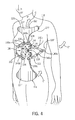
- FIG. 7 is a fragmentary side elevation view of a portion of the spinal brace of FIG. 4.
- FIG. 8 is a fragmentary side elevation view of a portion of the spinal brace of FIG. 4 .
- FIG. 1 shows a spinal brace 10 which is used by osteoporotic patients as shown, for example, in FIGS. 2-3.
- FIG. 1 Shown in FIG. 1 is a perspective view of a spinal brace 10 in accordance with the invention for lifting and straightening the curved upper spine of a person.
- Spinal brace 10 comprises a rigid anterior composite structure 12 and a thoracic support 14 .
- Anterior composite 12 comprises an upper anterior frame 16 and a lower anterior frame 18 , where each is secured to side plates 20 a,b of composite structure 12 as hereafter described.
- each side plate 20 a,b of anterior composite structure 12 serves to interface upper anterior frame 16 with lower anterior frame 18 and preferably aligns substantially with one side of the person's torso.
- Side plates 20 a,b have upper portions 22 a,b , lower portions 24 a,b , and outer surfaces 26 a,b.
- upper anterior frame 16 includes a sternum plate 28 , typically having two opposing ends 30 a,b , each of which is connected to a downwardly descending end 32 a,b .
- a sternum pad 34 is disposed on and affixed to sternum plate 28 for placement against the sternum. Virtually any fastening structure may be used for affixing sternum pad 34 to sternum plate 28 . Because such fastening and securement structures are well known in the art, a detailed disclosure of fasteners is not included herein.
- Sternum plate 28 is generally of a sufficient length and shape that it fits comfortably across the chest wall of person P.
- upper frame 12 ′ is one contiguous piece of a suitable shape and dimension for positioning against the person's body and includes a sternum plate 28 ′ that extends into a downwardly descending portion 32 a.
- the shape of the upper frame can be generally as desired, as long as the sternum pad is provided as described herein.
- the shape of upper frame 16 corresponds to the curvature of the upper chest wall so as to facilitate positioning of the upper frame against the body.
- a linkage structure 36 a,b which may be adjustable, provides secure attachments of upper frame 16 relative to the upper portions 22 a,b of side plates 20 a,b .
- Linkage structure 36 may be any structure that provides a linkage or bridge between upper frame 16 and side plates 20 a,b .
- linkage structure 36 a,b may comprise a bridge member 38 a,b that is firmly secured by at least one frame fastener 40 a,b to one downwardly descending end 32 a,b of upper frame 16 and by at least one side fastener 42 a,b to side plate 20 a,b where the securement precludes upper frame 16 from moving with respect to side plate 20 a,b .
- Linkage structure 36 may be adjusted by loosening fasteners 40 a,b and/or 42 a,b to permit the orientation of sternum plate 28 relative to side plates 20 a,b , and then tightening those fasteners when those elements are in the desired orientation.
- any other suitable linkage may be used to fixedly secure upper frame 16 from moving with respect to side plates 20 a,b .
- Such linkage stabilizes upper frame 16 within anterior composite 12 so that when spinal brace 10 is affixed to the body, sternum pad 34 does not shift around the chest wall.
- bridge 38 is shown as a bar and fasteners 40 , 42 are shown as bolts.
- bridge 38 may be any shape such as round, elliptical, octagonal, or hexagonal, for example, provided it immovably secures upper frame 16 to a side plate 20 a,b .
- bridge 38 can be loosened to allow upper frame 16 to be adjusted with respect to side plates 20 a,b .
- Fasteners 40 , 42 may be any suitable fastener that can be subsequently loosened for positionally adjusting upper frame 16 with respect to side plates 20 a,b .
- fasteners and bridging structures are well known in the art, no detailed disclosure is made herein.
- bridge members 38 a,b could be utilized to provide a pivotal linkage in place of the pivotal linkage described with respect to lower anterior frame 18 .
- Lower anterior frame 18 comprises two connecting components or ascending bars or bridge members 44 a,b , which are separated by a lateral plate 46 which cooperates with side plates 20 a,b to provide a pivotal linkage.
- a pubic pad 48 is disposed on lateral plate 46 for placement substantially on the pubic arch bone.
- Lateral plate 46 has two ends 50 a,b .
- a first pivotal connection 52 a,b disposed on each end 50 a,b , attaches one end 50 a,b to one ascending bar 44 a,b .
- lateral plate 46 is afforded a range of rotational motion with respect to a horizontal axis drawn through pivotal linkage 52 a,b .
- the rotational range of movement R is at least 180 degrees relative to a horizontal axis through ascending bars 44 a,b .
- the range of movement is 270 degrees, and most preferably 360 degrees.
- a second pivotal linkage connection 54 a,b is also associated with lower anterior frame 18 .
- Second pivotal linkage connection 54 a,b connects lower anterior frame 18 with side plates 20 a,b .
- Second pivotal linkage connection 54 a,b allows lower frame 18 to be pivoted about an axis running horizontally through pivotal linkage connection 54 a,b so as to achieve an optimum positioning of the brace on the person's body and an optimum lifting and extension of the spine.
- pivotal linkage connection 54 a,b lower anterior frame 18 has a rotational range of motion of at least 180 degrees relative to side plates 20 a,b through a horizontal axis running through such pivotal linkage system.
- pivotal linkage connections 52 a,b and 54 a,b may be provided by any suitable structure, including, for example, a rivet, bushing or other structure.
- pivotal linkage system 52 a,b it is through the rotational range of movement afforded by pivotal linkage system 52 a,b that when spinal brace 10 is affixed to the body of a person, sternum pad 34 and pubic pad 48 are pivotally adjusted with respect to each other to provide optimum lifting and fit, particularly for patients having exaggerated thoracic curvatures, and to provide extension of the spine.
- lower frame 18 has an inner surface 56 and an outer surface 57 .
- Pubic pad 48 is affixed to at least a portion of inner surface 56 , and is generally disposed on lateral plate 46 .
- pubic pad 48 is positioned against the pubic arch bone where it is held in place so it exerts a posterior-directed force against the pubic bone.
- an abdominal flexible web 58 serves to hold pubic pad 48 in position so it does not shift on the body.
- Abdominal flexible web 58 is extendable over the outer surface of lower torso frame 18 and is typically detachably securable to at least a portion of lower torso frame 18 .
- abdominal web 58 which generally should be fastened to frame 18 to exert a force from both sides at the same time, holds pubic pad 48 in place so it can exert a posterior force upon the lower pelvic area.
- the detachable securement of abdominal flexible web 58 to at least a portion of abdominal frame 18 results from the engagement of a fastening structure disposed on the abutting surfaces.
- Any suitable fastening structure may be used.
- One example of a suitable fastening structure includes a plurality of hooks 60 disposed on inner surface 62 of abdominal web 58 and a plurality of loops 64 disposed on a corresponding and complementary portion of outer surface 57 of lower frame 18 that lies in substantial horizontal alignment with the plurality of hooks 60 .
- abdominal flexible web 58 is secured to fasteners on both side plates 20 a,b .
- abdominal flexible web 58 is secured to a first web fastener 66 a, which is affixed to outer surface 26 a of side plate 20 a .
- Abdominal flexible web 58 then extends across the outer surface of lower anterior frame 18 to engage with a second web fastener 66 b on outer surface 26 b of the opposite side plate 20 b .
- web fasteners 66 a,b are affixed to lower portion 24 a,b of side plates 20 a,b .
- Web fasteners 66 a,b may be any suitable device for receiving a web of material and locking it in position; e.g., a frictional-locking clip. Because any suitable fasteners may find use in the spinal brace and fasteners are well known in the art, a detailed disclosure of these elements is not provided here.
- Abdominal web 58 is typically made from any flexible webbing material. Such materials may be natural or synthetic, elastic or non-elastic, and include, for example, cotton, fabrics, nylon, polyester, plastic, acrylic, vinyl, leather and other suitable materials.
- abdominal flexible web 58 is non-elastic in nature and may be any suitable width and length needed to secure pubic pad 48 in place. As abdominal flexible web 58 extends across lower frame 18 , it is detachably secured to at least a portion of lateral plate 46 .
- Side plates 20 a,b may have a side pad (not shown) affixed to the inner surface for comfort, as desired.
- the side pad if present, will have a length as desired.
- Sternum pad 34 , abdominal pad 48 , and thoracic pad 70 are dimensionally configured so that when spinal brace 10 is affixed in a normal wear position on the body and all three pads are secured in position, each pad 34 , 48 , and 70 disperses a force against an area of the body corresponding to its respective point of contact.
- pads 34 , 48 , and 70 may have a width of from about 13 ⁇ 4 inches to about 31 ⁇ 2 inches and a length of from about 3 inches to about 14 inches.
- pads 34 , 48 , 70 , and side pad 68 may have a thickness of from about 1 ⁇ 8 inch to about 3 ⁇ 4 inches, primarily to provide a comfortable fit against the body.
- Pads 34 , 48 , 70 , and 68 typically have a solid foam matrix-type composition. Any other suitable materials may, however, be used such as resinous compounds, fabrics, plastic, and others.
- pads 34 , 48 , 70 , and 68 may comprise a liner of a suitable material filled with air or a gas, a fluid, a gel, or other flowable material including for example, silica beads or other flowable solids.
- Thoracic support 14 comprises thoracic pad 70 , which is secured to a flexible thoracic web 72 .
- Thoracic pad 70 can be secured to thoracic web 72 by any suitable structure, such as adhesive, fasteners including a plurality of hooks in corresponding engagement with a plurality of loops, sewn stitches, or a looped structure for engaging a portion of the web, as examples. Because any suitable form of securement may be used and such forms of securement are well known in the art, a detailed disclosure is not provided here.
- Thoracic web 72 is generally in the form of a flexible strap. Thoracic web 72 can be made from virtually any suitable material, natural or synthetic, elastic or non-elastic, including, for example, fabrics, polyester, plastic, acrylic, vinyl, leather and other suitable materials. Thoracic web 72 has any suitable width and length as needed for securing thoracic pad 70 firmly in place.
- Thoracic web 72 is attachable to thoracic web fasteners 74 a,b disposed on outer surface 26 a,b of each side plate 20 a,b .
- Thoracic web fasteners 74 a,b are typically disposed on side plates 20 a,b at a point laterally above thoracic web fasteners 66 a,b .
- spinal brace 10 is affixed to the patient's body, thoracic pad 70 is held in place over the thoracic region of the back and at a point laterally above thoracic flexible web 58 .
- Upper frame 16 and lower frame 18 may be made of any suitable material that, when affixed to the body, would allow sternum pad 34 , thoracic pad 70 , and pubic pad 48 to create a three-point pressure system for extending and straightening the spine. Examples of such materials include metals, fiberglass, plastic, resins, and flexible materials.
- a method for lifting and straightening the spine of an osteoporotic patient using the aforedescribed spinal brace As spinal brace 10 has been described in detail above, further description is not provided here.
- the method comprises:
- brace 10 When brace 10 is in normal wearing position, lower portion 24 a,b of side plates 20 a,b moves toward lower frame 18 to exert a pressure on the pubic bone, and upper frame 16 is cantilevered backward to become pivotally positioned to interface with the chest wall. Such movement causes each of the three pads to exert a force against the patient's body in their respective area of contact. Sternum pad 34 and pubic pad 48 exert a posterior-directed force against the sternum and pubic arch bone, respectively in the direction of arrows A and A′ in FIG. 3 . Thoracic pad 70 exerts an opposing, anterior-directed force against the thoracic region of the back, with such force generally being directed in the direction of arrow A′ at a point laterally between the two posterior-directed forces. All three forces are typically directed substantially along a vertical axis. As a result of the opposing forces, the upper spine is dynamically lifted and straightened, regardless of the degree of thoracic curvature.
- FIGS. 2 and 3 show spinal brace 10 as it may be affixed to the body of an osteoporotic patient.
- FIG. 2 shows brace 10 as it is being used by a patient having a forward curvature of the thoracic spine;
- FIG. 3 shows the patient after having worn brace 10 to achieve a straightening and extension of the thoracic spine (assuming ideal conditions).
- upper frame 12 ′ is one contiguous piece of a suitable shape and dimension for positioning against the person's body and includes a lateral portion 28 ′ that extends into a downwardly descending portion 32 a .
- Downwardly descending portion 32 a is fixedly secured to side plate 20 a by linkage bar 38 a and fasteners 40 a and 42 a .
- a pivotal linkage 54 a attaches side plate 20 a to connecting component 44 a of lower frame 18 and pivotal linkage 52 a attaches lateral plate 46 to connecting component 44 a .
- Side plate 20 a substantially aligns with the side torso of the patient.
- sternum pad 34 is positioned against the sternum.
- Pubic pad 48 is secured against the pubic bone
- thoracic pad 70 is held firmly in place against the thoracic region of the back.
- Thoracic pad 70 is secured to a lateral area of plate 20 above the fastener that holds pubic pad 48 in place.
- FIG. 2 shows abdominal web 58 cut away so as to not conceal the positioning of pubic pad 48 .
- Spinal brace 110 includes an upper anterior member 112 , a lower anterior member 114 , a hinge mechanism 116 and a thoracic support 116 ′.
- Upper anterior member 112 performs the same function as upper frame 12 and sternum plate 14 previously described and includes a pad 118 for comfortably contacting the sternum and upper chest of a person P′ and applying a spine straightening and lifting force in the direction of arrow C on the upper chest and sternum.
- the forces applied by brace 110 are similar to those applied by brace 10 previously described.
- Member 112 is configured to comfortably fit over the upper chest of person P′ as illustrated in FIG. 4, and has two laterally extending wings 120 and 122 and a downwardly extending wing 124 terminating in an attaching portion 126 .
- the structural or outer portions 112 ′ and 114 ′ of members 112 and 114 can be constructed of a rigid material, such as metal, fiberglass or plastic, for example.
- Lower anterior member 114 performs the same function as lower anterior frame 18 previously described and extends downwardly generally to the pubic or pelvic region or area of person P′, and applies a force in the direction of arrow C′ similar to the force of arrow A′ previously described. Member 114 may also include a suitable pad 118 ′ for comfortably contacting the pelvic or pubic area of person P′.
- Hinge mechanism 116 includes a hinged joint 128 and upper and lower hinge flanges 130 and 132 to which the respective ends of upper and lower anterior members 112 and 114 are mounted by use of threaded fasteners 134 or other suitable fasteners as desired.
- Hinged joint 128 can incorporate a one-way clutch mechanism so that the rotation or pivoting of hinged joint 128 is permitted only in one direction (in the direction of allowing the back or upper torso of person P′ to be moved in an upward or spine straightening direction).
- One-way clutches are well known in the art and are described in detail in U.S. Pat. No. 5,328,446, issued Jul. 12, 1994 from U.S. Ser. No. 968,542, filed Oct. 29, 1992, the disclosure of which is hereby incorporated by reference.
- the one-way clutch may also have a “freewheeling mode” in which hinged joint 128 can pivot freely.
- hinged joint 128 allows (but does not urge) free movement in the spine straightening direction and movement in the opposite direction is prevented.
- the clutch can be of a type that allows movement in continuous or very small graduations and may be a sprague clutch, a ramp and roller clutch or a mechanical diode clutch. Alternatively, a ratchet-type mechanism could be employed.
- the clutch mode can be changed from freewheeling to one-way by the patient or the doctor, for example.
- Hinged joint 128 includes a pivot shaft 136 about which hinge mechanism 116 rotates.
- Hinge flanges 130 and 132 include suitable hinge bores to allow mounting to pivot shaft 136 .
- the degree of rotation or pivoting can be substantial and may be in excess of 90° or 180° as desired.
- Thoracic support 116 ′ is composed of elastic strips or webs 140 a-f that encircle person P′ or the wearer as illustrated in FIGS. 4-6.
- a posterior pad 142 is located across the back of person P′ and straps 140 a and 140 f are secured thereto.
- Buckles 144 a-d are provided to permit adjustment of the tension of straps 140 a-f to maintain brace 110 in the desired position and orientation on person P′ and provide a force in the direction of arrow C′′, similar to the force described with respect to arrow A′′.
Abstract
Description
Claims (28)
Priority Applications (1)
| Application Number | Priority Date | Filing Date | Title |
|---|---|---|---|
| US09/569,726 US6471665B1 (en) | 1999-05-10 | 2000-05-10 | Postural dynamic spinal extension brace and method |
Applications Claiming Priority (2)
| Application Number | Priority Date | Filing Date | Title |
|---|---|---|---|
| US13327199P | 1999-05-10 | 1999-05-10 | |
| US09/569,726 US6471665B1 (en) | 1999-05-10 | 2000-05-10 | Postural dynamic spinal extension brace and method |
Publications (1)
| Publication Number | Publication Date |
|---|---|
| US6471665B1 true US6471665B1 (en) | 2002-10-29 |
Family
ID=26831220
Family Applications (1)
| Application Number | Title | Priority Date | Filing Date |
|---|---|---|---|
| US09/569,726 Expired - Fee Related US6471665B1 (en) | 1999-05-10 | 2000-05-10 | Postural dynamic spinal extension brace and method |
Country Status (1)
| Country | Link |
|---|---|
| US (1) | US6471665B1 (en) |
Cited By (27)
| Publication number | Priority date | Publication date | Assignee | Title |
|---|---|---|---|---|
| FR2909861A1 (en) * | 2006-12-19 | 2008-06-20 | Patrick Faouen | Orthopedic device for posture correction, has posterior lumbar support element with symmetric support parts separated by free space and contacting on both sides of spinal column of user without contacting spinal line of spinal column |
| US20100069806A1 (en) * | 2008-09-12 | 2010-03-18 | Carey Paul Jinright | Adjustable brace for correcting a forward lean |
| US20110105971A1 (en) * | 2009-11-04 | 2011-05-05 | Arni Thor Ingimundarson | Thoracic lumbar sacral orthosis |
| US20110152737A1 (en) * | 2009-12-22 | 2011-06-23 | Steven Burke | Hyperextension Brace |
| ITVR20100065A1 (en) * | 2010-03-30 | 2011-10-01 | Fgp Srl | THREE-POINT ORTHOPEDIC SUPPORT FOR THREE POINTS OR DORSAL ORTHOSES FOR VERTEBRAL COLUMN |
| ITMI20102189A1 (en) * | 2010-11-25 | 2012-05-26 | Orthoservice Ag | PERFECT ORTHOPEDIC BUSHING HYPERESTENSOR |
| WO2014182742A1 (en) * | 2013-05-06 | 2014-11-13 | Aspen Medical Partners, Llc | Scoliosis brace |
| US8926537B2 (en) | 2009-02-26 | 2015-01-06 | Ossur Hf | Orthopedic device for treatment of the back |
| US20150223962A1 (en) * | 2012-10-01 | 2015-08-13 | Kawamura Gishi Co., Ltd. | Spinal orthosis |
| US9314363B2 (en) | 2013-01-24 | 2016-04-19 | Ossur Hf | Orthopedic device for treating complications of the hip |
| US9370440B2 (en) | 2012-01-13 | 2016-06-21 | Ossur Hf | Spinal orthosis |
| US20160250062A1 (en) * | 2013-09-20 | 2016-09-01 | Becq B.V. | Wearable support structure and method of supporting a torso |
| US9439800B2 (en) | 2009-01-14 | 2016-09-13 | Ossur Hf | Orthopedic device, use of orthopedic device and method for producing same |
| US9468554B2 (en) | 2013-01-24 | 2016-10-18 | Ossur Iceland Ehf | Orthopedic device for treating complications of the hip |
| US9554935B2 (en) | 2013-01-24 | 2017-01-31 | Ossur Hf | Orthopedic device for treating complications of the hip |
| US9572705B2 (en) | 2012-01-13 | 2017-02-21 | Ossur Hf | Spinal orthosis |
| ITUA20161623A1 (en) * | 2016-03-15 | 2017-09-15 | Pasquale Carmelo De | ORTOPEDIC BUST HYPERESTENSOR WITH 3 POINTS BIOMECHANICAL |
| US9795500B2 (en) | 2013-01-24 | 2017-10-24 | Ossur Hf | Orthopedic device for treating complications of the hip |
| US9872794B2 (en) | 2012-09-19 | 2018-01-23 | Ossur Hf | Panel attachment and circumference adjustment systems for an orthopedic device |
| US10159592B2 (en) | 2015-02-27 | 2018-12-25 | Ossur Iceland Ehf | Spinal orthosis, kit and method for using the same |
| US10265210B2 (en) | 2013-05-06 | 2019-04-23 | Aspen Medical Partners, Llc | Scoliosis brace |
| US10561520B2 (en) | 2015-02-27 | 2020-02-18 | Ossur Iceland Ehf | Spinal orthosis, kit and method for using the same |
| JP2020081072A (en) * | 2018-11-19 | 2020-06-04 | 鈴木義肢装具株式会社 | Medical corset |
| RU2737781C1 (en) * | 2020-05-15 | 2020-12-02 | Сергей Викторович Василевич | Extension corset |
| US11000439B2 (en) | 2017-09-28 | 2021-05-11 | Ossur Iceland Ehf | Body interface |
| US11246734B2 (en) | 2017-09-07 | 2022-02-15 | Ossur Iceland Ehf | Thoracic lumbar sacral orthosis attachment |
| US11324622B1 (en) | 2019-08-08 | 2022-05-10 | Preferred Prescription, Inc. | Back brace belt and apparatus, and method of belt length adjustment therefor |
Citations (13)
| Publication number | Priority date | Publication date | Assignee | Title |
|---|---|---|---|---|
| US2582930A (en) * | 1949-05-05 | 1952-01-15 | Blairs Braces Inc | Surgical brace |
| US3094984A (en) * | 1961-09-01 | 1963-06-25 | Florida Brace Corp | Surgical brace |
| US3095875A (en) * | 1961-08-28 | 1963-07-02 | Florida Brace Corp | Surgical brace |
| US3220407A (en) * | 1962-10-08 | 1965-11-30 | S H Camp & Company | Hyperextension back brace |
| US3351053A (en) * | 1962-11-13 | 1967-11-07 | Florida Brace Corp | Flexion back brace |
| US3548817A (en) * | 1968-04-29 | 1970-12-22 | Ronald F Mittasch | Orthopedic traction belt |
| US4285336A (en) | 1979-10-23 | 1981-08-25 | Orthomedics, Inc. | Scoliosis orthotic system |
| US4691696A (en) | 1985-02-01 | 1987-09-08 | 102160 Canada Inc. | Lumbar spinal brace |
| US4829989A (en) * | 1985-06-17 | 1989-05-16 | Deamer Richard M | Stoop laborer's body support having hinge with adjustable spring biasing |
| US5176622A (en) * | 1991-10-04 | 1993-01-05 | Bndr Associates | Stoop labor assist device |
| US5328446A (en) | 1992-10-29 | 1994-07-12 | Becker Orthopedic Appliance Company | Orthopedic joint and method for treating a contracture |
| US5503621A (en) * | 1994-09-09 | 1996-04-02 | Boston Brace International, Inc. | Body brace |
| US5569171A (en) | 1992-04-29 | 1996-10-29 | Muncy; Ron | Chiropractic brace |
-
2000
- 2000-05-10 US US09/569,726 patent/US6471665B1/en not_active Expired - Fee Related
Patent Citations (13)
| Publication number | Priority date | Publication date | Assignee | Title |
|---|---|---|---|---|
| US2582930A (en) * | 1949-05-05 | 1952-01-15 | Blairs Braces Inc | Surgical brace |
| US3095875A (en) * | 1961-08-28 | 1963-07-02 | Florida Brace Corp | Surgical brace |
| US3094984A (en) * | 1961-09-01 | 1963-06-25 | Florida Brace Corp | Surgical brace |
| US3220407A (en) * | 1962-10-08 | 1965-11-30 | S H Camp & Company | Hyperextension back brace |
| US3351053A (en) * | 1962-11-13 | 1967-11-07 | Florida Brace Corp | Flexion back brace |
| US3548817A (en) * | 1968-04-29 | 1970-12-22 | Ronald F Mittasch | Orthopedic traction belt |
| US4285336A (en) | 1979-10-23 | 1981-08-25 | Orthomedics, Inc. | Scoliosis orthotic system |
| US4691696A (en) | 1985-02-01 | 1987-09-08 | 102160 Canada Inc. | Lumbar spinal brace |
| US4829989A (en) * | 1985-06-17 | 1989-05-16 | Deamer Richard M | Stoop laborer's body support having hinge with adjustable spring biasing |
| US5176622A (en) * | 1991-10-04 | 1993-01-05 | Bndr Associates | Stoop labor assist device |
| US5569171A (en) | 1992-04-29 | 1996-10-29 | Muncy; Ron | Chiropractic brace |
| US5328446A (en) | 1992-10-29 | 1994-07-12 | Becker Orthopedic Appliance Company | Orthopedic joint and method for treating a contracture |
| US5503621A (en) * | 1994-09-09 | 1996-04-02 | Boston Brace International, Inc. | Body brace |
Cited By (52)
| Publication number | Priority date | Publication date | Assignee | Title |
|---|---|---|---|---|
| FR2909861A1 (en) * | 2006-12-19 | 2008-06-20 | Patrick Faouen | Orthopedic device for posture correction, has posterior lumbar support element with symmetric support parts separated by free space and contacting on both sides of spinal column of user without contacting spinal line of spinal column |
| US20100069806A1 (en) * | 2008-09-12 | 2010-03-18 | Carey Paul Jinright | Adjustable brace for correcting a forward lean |
| US7837639B2 (en) * | 2008-09-12 | 2010-11-23 | Carey Paul Jinright | Adjustable brace for correcting a forward lean |
| US9439800B2 (en) | 2009-01-14 | 2016-09-13 | Ossur Hf | Orthopedic device, use of orthopedic device and method for producing same |
| US8945034B2 (en) | 2009-02-26 | 2015-02-03 | Ossur Hf | Orthopedic device for treatment of the back |
| US9414953B2 (en) | 2009-02-26 | 2016-08-16 | Ossur Hf | Orthopedic device for treatment of the back |
| US10828186B2 (en) | 2009-02-26 | 2020-11-10 | Ossur Hf | Orthopedic device for treatment of the back |
| US8926537B2 (en) | 2009-02-26 | 2015-01-06 | Ossur Hf | Orthopedic device for treatment of the back |
| US9597219B2 (en) | 2009-11-04 | 2017-03-21 | Ossur Hf | Thoracic lumbar sacral orthosis |
| US8657769B2 (en) | 2009-11-04 | 2014-02-25 | Ossur Hf | Thoracic lumbar sacral orthosis |
| US9220625B2 (en) | 2009-11-04 | 2015-12-29 | Ossur Hf | Thoracic lumbar sacral orthosis |
| US10617552B2 (en) | 2009-11-04 | 2020-04-14 | Ossur Hf | Thoracic lumbar sacral orthosis |
| US20110105971A1 (en) * | 2009-11-04 | 2011-05-05 | Arni Thor Ingimundarson | Thoracic lumbar sacral orthosis |
| US20110152737A1 (en) * | 2009-12-22 | 2011-06-23 | Steven Burke | Hyperextension Brace |
| US8556840B2 (en) | 2009-12-22 | 2013-10-15 | Aspen Medical Partners, Llc | Hyperextension brace |
| ITVR20100065A1 (en) * | 2010-03-30 | 2011-10-01 | Fgp Srl | THREE-POINT ORTHOPEDIC SUPPORT FOR THREE POINTS OR DORSAL ORTHOSES FOR VERTEBRAL COLUMN |
| EP2457544A1 (en) * | 2010-11-25 | 2012-05-30 | Orthoservice AG | Improved hyperextension orthopaedic corset |
| ITMI20102189A1 (en) * | 2010-11-25 | 2012-05-26 | Orthoservice Ag | PERFECT ORTHOPEDIC BUSHING HYPERESTENSOR |
| US10898365B2 (en) | 2012-01-13 | 2021-01-26 | Ossur Hf | Spinal orthosis |
| US9572705B2 (en) | 2012-01-13 | 2017-02-21 | Ossur Hf | Spinal orthosis |
| US9370440B2 (en) | 2012-01-13 | 2016-06-21 | Ossur Hf | Spinal orthosis |
| US9872794B2 (en) | 2012-09-19 | 2018-01-23 | Ossur Hf | Panel attachment and circumference adjustment systems for an orthopedic device |
| US11484428B2 (en) | 2012-09-19 | 2022-11-01 | Ossur Hf | Panel attachment and circumference adjustment systems for an orthopedic device |
| US10980657B2 (en) | 2012-09-19 | 2021-04-20 | Ossur Hf | Panel attachment and circumference adjustment systems for an orthopedic device |
| US20150223962A1 (en) * | 2012-10-01 | 2015-08-13 | Kawamura Gishi Co., Ltd. | Spinal orthosis |
| US9855162B2 (en) * | 2012-10-01 | 2018-01-02 | Kawamura Gishi Co., Ltd. | Spinal orthosis |
| US9987158B2 (en) | 2013-01-24 | 2018-06-05 | Ossur Hf | Orthopedic device for treating complications of the hip |
| US10357391B2 (en) | 2013-01-24 | 2019-07-23 | Ossur Hf | Orthopedic device for treating complications of the hip |
| US9468554B2 (en) | 2013-01-24 | 2016-10-18 | Ossur Iceland Ehf | Orthopedic device for treating complications of the hip |
| US9393144B2 (en) | 2013-01-24 | 2016-07-19 | Ossur Hf | Orthopedic device for treating complications of the hip |
| US9554935B2 (en) | 2013-01-24 | 2017-01-31 | Ossur Hf | Orthopedic device for treating complications of the hip |
| US11259948B2 (en) | 2013-01-24 | 2022-03-01 | Ossur Hf | Orthopedic device for treating complications of the hip |
| US9314363B2 (en) | 2013-01-24 | 2016-04-19 | Ossur Hf | Orthopedic device for treating complications of the hip |
| US9795500B2 (en) | 2013-01-24 | 2017-10-24 | Ossur Hf | Orthopedic device for treating complications of the hip |
| US10265210B2 (en) | 2013-05-06 | 2019-04-23 | Aspen Medical Partners, Llc | Scoliosis brace |
| US11311402B2 (en) | 2013-05-06 | 2022-04-26 | Aspen Medical Partners, Llc | Scoliosis brace |
| WO2014182742A1 (en) * | 2013-05-06 | 2014-11-13 | Aspen Medical Partners, Llc | Scoliosis brace |
| RU2629794C2 (en) * | 2013-05-06 | 2017-09-04 | ЭСПЕН МЕДИКАЛ ПАРТНЕРЗ, ЭлЭлСи | Orthesis for scoliosis treatment |
| US10561518B2 (en) * | 2013-09-20 | 2020-02-18 | Laevo B.V. | Wearable support structure and method of supporting a torso |
| US20160250062A1 (en) * | 2013-09-20 | 2016-09-01 | Becq B.V. | Wearable support structure and method of supporting a torso |
| US10561520B2 (en) | 2015-02-27 | 2020-02-18 | Ossur Iceland Ehf | Spinal orthosis, kit and method for using the same |
| US11273064B2 (en) | 2015-02-27 | 2022-03-15 | Ossur Iceland Ehf | Spinal orthosis, kit and method for using the same |
| US10159592B2 (en) | 2015-02-27 | 2018-12-25 | Ossur Iceland Ehf | Spinal orthosis, kit and method for using the same |
| US11571323B2 (en) | 2015-02-27 | 2023-02-07 | Ossur Iceland Ehf | Spinal orthosis, kit and method for using the same |
| ITUA20161623A1 (en) * | 2016-03-15 | 2017-09-15 | Pasquale Carmelo De | ORTOPEDIC BUST HYPERESTENSOR WITH 3 POINTS BIOMECHANICAL |
| US11246734B2 (en) | 2017-09-07 | 2022-02-15 | Ossur Iceland Ehf | Thoracic lumbar sacral orthosis attachment |
| US11684506B2 (en) | 2017-09-07 | 2023-06-27 | Ossur Iceland Ehf | Thoracic lumbar sacral orthosis attachment |
| US11000439B2 (en) | 2017-09-28 | 2021-05-11 | Ossur Iceland Ehf | Body interface |
| US11850206B2 (en) | 2017-09-28 | 2023-12-26 | Ossur Iceland Ehf | Body interface |
| JP2020081072A (en) * | 2018-11-19 | 2020-06-04 | 鈴木義肢装具株式会社 | Medical corset |
| US11324622B1 (en) | 2019-08-08 | 2022-05-10 | Preferred Prescription, Inc. | Back brace belt and apparatus, and method of belt length adjustment therefor |
| RU2737781C1 (en) * | 2020-05-15 | 2020-12-02 | Сергей Викторович Василевич | Extension corset |
Similar Documents
| Publication | Publication Date | Title |
|---|---|---|
| US6471665B1 (en) | Postural dynamic spinal extension brace and method | |
| US11850206B2 (en) | Body interface | |
| US5486157A (en) | Dynamic multi-angular ankle and foot orthosis device | |
| US5632724A (en) | Hyperextension thoraco-lumbar brace | |
| US5840051A (en) | Flexible back, neck and shoulder brace | |
| US3771513A (en) | Spinal brace | |
| US7122016B1 (en) | Knee brace immobilizer | |
| US5599287A (en) | Hyperextension orthotic apparatus useful for treating pain associated with spinal disorders | |
| US8066654B2 (en) | Adjustable extension compression posterior spinal orthosis and method | |
| US3313297A (en) | Cervical splint | |
| US3945376A (en) | Orthopedic brace (orthesis) | |
| US5569171A (en) | Chiropractic brace | |
| US5662597A (en) | Gravity traction device | |
| US7785282B2 (en) | Spinal orthosis | |
| US7037284B2 (en) | Specific pelvic compression belt | |
| WO2001066051A3 (en) | Thoraco-lumbo-sacral orthosis | |
| US3827429A (en) | Ambulatory orthopedic traction apparatus | |
| US20050203453A1 (en) | Adjustable spinal brace | |
| JPH0366894B2 (en) | ||
| US4930499A (en) | Sacral brace | |
| US20040193086A1 (en) | Dynamic position adjustment device for extremities of the human body | |
| US10265210B2 (en) | Scoliosis brace | |
| US20200170822A1 (en) | Posture and Lifting Orthotic | |
| US20140074003A1 (en) | Posture and Lifting Orthotic | |
| CN211382023U (en) | Appliance for treating knee osteoarthritis |
Legal Events
| Date | Code | Title | Description |
|---|---|---|---|
| AS | Assignment |
Owner name: BECKER ORTHOPEDIC APPLIANCE COMPANY, MICHIGAN Free format text: ASSIGNMENT OF ASSIGNORS INTEREST;ASSIGNOR:MILBOURN, JACK R.;REEL/FRAME:011105/0919 Effective date: 20000510 Owner name: BECKER ORTHOPEDIC APPLIANCE COMPANY, MICHIGAN Free format text: ASSIGNMENT OF ASSIGNORS INTEREST;ASSIGNORS:CAMPBELL, JAMES H.;ZALINSKI, NICHOLAS C.;REEL/FRAME:011105/0937 Effective date: 20000907 |
|
| CC | Certificate of correction | ||
| FPAY | Fee payment |
Year of fee payment: 4 |
|
| REMI | Maintenance fee reminder mailed | ||
| FPAY | Fee payment |
Year of fee payment: 8 |
|
| SULP | Surcharge for late payment |
Year of fee payment: 7 |
|
| REMI | Maintenance fee reminder mailed | ||
| LAPS | Lapse for failure to pay maintenance fees | ||
| STCH | Information on status: patent discontinuation |
Free format text: PATENT EXPIRED DUE TO NONPAYMENT OF MAINTENANCE FEES UNDER 37 CFR 1.362 |
|
| FP | Lapsed due to failure to pay maintenance fee |
Effective date: 20141029 |