EP2994018B1 - Structure de siège ainsi que siège - Google Patents
Structure de siège ainsi que siège Download PDFInfo
- Publication number
- EP2994018B1 EP2994018B1 EP14725036.9A EP14725036A EP2994018B1 EP 2994018 B1 EP2994018 B1 EP 2994018B1 EP 14725036 A EP14725036 A EP 14725036A EP 2994018 B1 EP2994018 B1 EP 2994018B1
- Authority
- EP
- European Patent Office
- Prior art keywords
- seating furniture
- guide part
- furniture structure
- carrier unit
- structure according
- Prior art date
- Legal status (The legal status is an assumption and is not a legal conclusion. Google has not performed a legal analysis and makes no representation as to the accuracy of the status listed.)
- Not-in-force
Links
- 230000007246 mechanism Effects 0.000 claims description 11
- 230000005540 biological transmission Effects 0.000 claims description 9
- 230000008878 coupling Effects 0.000 claims description 8
- 238000010168 coupling process Methods 0.000 claims description 8
- 238000005859 coupling reaction Methods 0.000 claims description 8
- 238000006073 displacement reaction Methods 0.000 description 10
- NJPPVKZQTLUDBO-UHFFFAOYSA-N novaluron Chemical compound C1=C(Cl)C(OC(F)(F)C(OC(F)(F)F)F)=CC=C1NC(=O)NC(=O)C1=C(F)C=CC=C1F NJPPVKZQTLUDBO-UHFFFAOYSA-N 0.000 description 6
- 230000008859 change Effects 0.000 description 3
- 239000000758 substrate Substances 0.000 description 3
- 230000000694 effects Effects 0.000 description 2
- 230000004308 accommodation Effects 0.000 description 1
- 239000004744 fabric Substances 0.000 description 1
- 239000000835 fiber Substances 0.000 description 1
- 230000009467 reduction Effects 0.000 description 1
- 230000001360 synchronised effect Effects 0.000 description 1
- 239000004753 textile Substances 0.000 description 1
- 210000001364 upper extremity Anatomy 0.000 description 1
Images


Classifications
-
- A—HUMAN NECESSITIES
- A47—FURNITURE; DOMESTIC ARTICLES OR APPLIANCES; COFFEE MILLS; SPICE MILLS; SUCTION CLEANERS IN GENERAL
- A47C—CHAIRS; SOFAS; BEDS
- A47C7/00—Parts, details, or accessories of chairs or stools
- A47C7/50—Supports for the feet or the legs coupled to fixed parts of the chair
- A47C7/506—Supports for the feet or the legs coupled to fixed parts of the chair of adjustable type
-
- A—HUMAN NECESSITIES
- A47—FURNITURE; DOMESTIC ARTICLES OR APPLIANCES; COFFEE MILLS; SPICE MILLS; SUCTION CLEANERS IN GENERAL
- A47C—CHAIRS; SOFAS; BEDS
- A47C1/00—Chairs adapted for special purposes
- A47C1/02—Reclining or easy chairs
- A47C1/031—Reclining or easy chairs having coupled concurrently adjustable supporting parts
- A47C1/034—Reclining or easy chairs having coupled concurrently adjustable supporting parts the parts including a leg-rest or foot-rest
- A47C1/035—Reclining or easy chairs having coupled concurrently adjustable supporting parts the parts including a leg-rest or foot-rest in combination with movably coupled seat and back-rest, i.e. the seat and back-rest being movably coupled in such a way that the extension mechanism of the foot-rest is actuated at least by the relative movements of seat and backrest
- A47C1/0355—Reclining or easy chairs having coupled concurrently adjustable supporting parts the parts including a leg-rest or foot-rest in combination with movably coupled seat and back-rest, i.e. the seat and back-rest being movably coupled in such a way that the extension mechanism of the foot-rest is actuated at least by the relative movements of seat and backrest actuated by linkages, e.g. lazy-tongs mechanisms
Definitions
- the invention relates to a seating furniture structure comprising a carrier unit and a seat part arrangement movably mounted relative to the carrier unit, and having a leg rest arrangement which guides a guide member pivotally mounted relative to the carrier unit and / or seat part assembly about a seat transverse axis and a relative to the guide member by means of at least one mechanical tension cord control displaceable support carriage includes, wherein the Glasstrang facedung is forcibly coupled with a pivoting mechanism of the guide member such that the support carriage is movable relative to the guide member depending on a pivotal position of the guide member between different end positions.
- Such a seating structure is from the DE 20 2004 011 998 U1 known.
- the known seating furniture structure is part of an armchair, which comprises a relative to a seat pivoting backrest and a swing-leg rest.
- the seating furniture structure has a support unit mounted on a foot, on which a seat part arrangement is held approximately horizontally displaceable.
- On the rear side the seat part arrangement is flanked by a backrest arrangement.
- Front side of the seat part assembly includes a leg rest assembly comprising a pivotally held guide member.
- the guide member is pivotally mounted about a seat transverse axis between a pivoted under the seat part assembly rest position and an extension of the seat part assembly projecting forward functional position.
- a support carriage On the guide part, a support carriage is guided linearly displaceable, which defines a long support surface for the leg support assembly in the extended end position.
- the leg rest assembly In displaced to the seat part assembly out, retracted position of the support carriage, the leg rest assembly has a minimum possible length on. The change in the length of the leg rest assembly serves to pivot the leg rest assembly under the seat member assembly without hitting a ground or foot rest of the armchair in a vertically downwardly intermediate position.
- the object of the invention is to provide a seating furniture structure of the type mentioned, which allows a compact design of a Switzerlandstrang facedung for the support carriage and a large adjustment of the receiving carriage.
- the Buchstrang facedung has a plurality of adjacent deflection over which a Switzerlandstrang the Switzerlandstrang dealtung is guided alternately in opposite directions, and at least one deflection is held variable position and is by means of a forced coupling unit with the pivoting mechanism of the guide member in active connection.
- the opposing deflection of the tension cord to adjacent deflection allows a compact design of Buchstrang facedung at the same time large path compensation for a displacement path of the support carriage.
- the support carriage is preferably mounted linearly movable relative to the guide member. It is also possible, the support carriage by means of a parallel link arrangement about to shift parallel relative to the guide part.
- deflecting deflection rollers or guide rollers are preferably provided. It is also possible to provide deflecting elements as deflection elements, on which the tension cord is deflected in a sliding manner. Among the several adjacent deflecting elements are at least two deflecting elements to understand, over which the tensile strand is deflected in opposite directions. In the case of more than two adjacent deflecting elements, the tensile strand is alternately deflected in opposite directions about the respectively adjacent deflecting elements.
- the drawstring is preferably a drawstring in the form of a fabric band made of textile or plastic fibers.
- a pull cord instead of a drawstring and a pull rope or a pull strap may be provided. It is possible to control the support slide only by means of a single pull string control and by means of a single pull string.
- two identically designed to each other and spaced in the seat transverse direction termed as two identically designed to each other and spaced in the seat transverse direction Zastrang horrungen are provided which engage on opposite sides of the support carriage, so as to effect a synchronous and uniform longitudinal displacement, ie parallel displacement of the support carriage relative to the guide member.
- the support slide relative to the guide member is held by means of a spring force arrangement in an extended end position in which the leg rest assembly has its greatest possible longitudinal extent.
- the tension cord control counteracts the spring force of the spring force arrangement in order to displace the support slide in the direction of the retracted end position relative to the guide part.
- the solution according to the invention is particularly advantageously suitable for seating furniture provided with upholstery in the region of the seat part arrangement and the leg support arrangement.
- the support unit of the seating structure is either supported directly on a substrate in the manner of a support frame, or it is rotatably mounted on a pedestal about a vertical axis of rotation, wherein the pedestal stands up on a corresponding ground.
- the seating furniture structure comprises a backrest arrangement which adjoins the seat part arrangement on the rear side and which can be kept adjustable in its inclination relative to the carrier unit and / or relative to the seat part arrangement.
- the seat furniture structure may be assigned to adjust the seat part assembly and the leg rest assembly and / or the backrest assembly at least one, preferably electromotive, drive unit, which is advantageously attached to the support unit. It is also possible for the adjustment of the seat part assembly on the one hand and an adjustment of an associated backrest arrangement on the other hand to provide two different, preferably electromotive, drive units.
- a corresponding electromotive drive unit has, in addition to an electric motor, a suitable transmission and drive transmission means, which are in operative connection with the seat part arrangement and / or the backrest arrangement.
- the tension cord is fastened with an end region on the carrier unit and with its opposite end region on the support carriage.
- the carrier unit comprises a cross member extending in the transverse direction of the seat, to which the pull cord is fastened with its one end region.
- the tension cord control is arranged adjacent to the pivoting mechanism of the guide part on a front part of the carrier unit facing the guide part.
- two adjacent deflecting elements are arranged on opposite legs of a rocker pivotally mounted about a central rocking axis.
- the deflecting elements are each mounted at the same distance from the central rocker axis on the opposite legs of the rocker.
- deflecting deflection rollers are preferably provided.
- the tension cord is deflected in opposite directions via the adjacent deflecting elements of the rocker, by being guided on the one guide roller in a first direction of rotation and on the second guide roller in opposite directions of rotation over the pulleys.
- a stationary deflecting element is arranged on the carrier unit.
- a stationary deflecting a deflection roller is preferably provided which is rotatably mounted about an axis of rotation stationary on the carrier unit.
- adjacent to the support slide deflection is mounted on a pivot lever, which is in operative connection with the pivot mechanism of the guide member.
- the deflecting element adjacent to the support carriage is preferably designed as a deflection roller, which is rotatably mounted on an end region of the pivot lever. All pulleys of Switzerlandstrang facedung have mutually parallel axes of rotation.
- the tensile strand is alternately deflected in opposite directions from its attached to the carrier unit end portion via the two deflecting elements of the rocker, passed over the stationary deflecting element and finally over the deflector mounted on the pivot lever and opens into the end portion attached to the support carriage.
- the tension cord is deflected leporelloartig alternately over the various deflecting elements.
- a control lever kinematics for positive coupling of Switzerlandstrang facedung with the pivoting mechanism of the guide member which couples the adjacent the support slide deflecting pivot lever with the rocker such that the support slide in a particular perpendicular to a substrate down projecting pivot position the guide member occupies its rear end position displaced to the seat part arrangement.
- This embodiment is based on the recognition that when the leg rest arrangement is pivoted downward below the seat part arrangement, the distance between an underside of the seat part arrangement and a substrate on which the seating furniture structure rests is not so great that the leg rest arrangement can be pushed into its front, extended end position moved Auflagschlitten can be pivoted without touching the ground.
- the control lever kinematics controls the Switzerlandstrang facedung due to the mechanical coupling with the pivoting mechanism of the guide member the support slide so that the support slide assumes its fully retracted end position in a corresponding to the ground down projecting position of the guide member.
- control lever kinematics comprises a control arm acting on the pivot lever and a double lever mounted on the carrier unit, on which the control arm engages.
- the control arm and the double lever form a kinematic chain between the swivel lever of the pull string control and the pull string control rocker.
- the double lever is coupled by means of a transmission lever with the rocker of Switzerlandstrang facedung.
- the transmission lever is also part of the kinematic chain of the control lever kinematics in order to effect the forced coupling with the train train control.
- the invention also relates to a chair with a seating structure as set forth in at least one of the paragraphs described above.
- a chair is preferably provided, comprising upholstery parts that at least partially cover and / or surround the seating furniture structure.
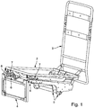
- the seating furniture structure 1 has a carrier unit 5, which is mounted stationary on a pedestal, not shown.
- the carrier unit 5 may be rotatably mounted relative to the pedestal about a vertical axis, so that the entire seating furniture structure 1 can be rotated about this vertical axis relative to the pedestal.
- the seating structure 1 is therefore part of a swivel chair.
- the seating furniture structure 1 has a seat part arrangement 2, which can be adjusted relative to the carrier unit 5 by means of a spring kinematics not specifically described substantially parallel in its seat plane in the seat longitudinal direction.
- a backrest assembly 3 is mounted, which can be adjusted relative to the support unit 5 and relative to the seat part assembly 2 in its inclination.
- an electromotive drive unit is provided in each case, which is mounted on the carrier unit 5.
- the carrier unit 5 has two lateral side members 12, which are parallel to each other and are connected to each other in a front leg area via a cross member 11.
- the cross member 11 is also part of the support unit 5.
- a leg rest assembly 4 is pivotally supported on the support unit 5.
- the leg rest arrangement 4 is about a pivot axis S (in the seat transverse direction) Fig. 3 ) is mounted pivotably on the carrier unit 5.
- the leg rest assembly 4 is also operatively connected via two control levers 27 with the lever kinematics for adjusting the seat part assembly 2.
- the leg rest arrangement 4 has a pivotable guide part 9 which is mounted on the longitudinal members 12 about the pivot axis S and is articulated to the control levers 27 with control tabs projecting on the rear side.
- a support carriage 10 is mounted linearly displaceable.
- the support carriage 10 is relative to the guide member 9 by means of a spring assembly, not shown in the unloaded state in an extended end position according to Fig. 2 held, in which the support carriage 10 is moved relative to the guide member 9 relative to a front cross section of the seat part assembly 2 forward to an end stop on the guide member 9.
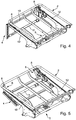
- the leg rest arrangement 4 is pivotable downwards from an end position extended in the extension of the seat part arrangement 2 to a lower end position concealed below the seat part arrangement 2 (US Pat. Fig. 5 ).
- the support carriage 10 moves relative to the guide part 9 into a retracted rest position, namely its rear end position , shifted, in which the support carriage 10 is moved in the direction of the front transverse profile of the seat part assembly 2.
- the displacement of the support carriage 10 against the spring force of the spring arrangement, not shown along corresponding guide rails of the guide member 9 is effected by two identically designed Werner 6, which are arranged on the inside at the front end portions of the longitudinal member 12 of the support unit 5.
- the two Switzerlandstrangmatiungen 6 are positioned below the seat part assembly 2.
- Each pull string control 6 has in each case a drawstring 8 which is fastened with its rear end region 13 on the cross member 11 of the support unit 5 and with its front end portion 14 on the support slide 10.
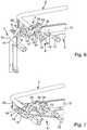
- the drawstring 8 is between the two end portions 13 and 14 in the manner described in more detail below about a plurality of guide rollers 15 to 18 respectively oppositely reversed and thus approximately leporelloartig deflected, wherein the drawstring 8, starting from the attached to the cross member 11 end portion 13 in the illustration according to the Fig. 6 to 15 first clockwise about a first guide roller 15, then counterclockwise about a second guide roller 16, then again clockwise about a third guide roller 17 and finally counterclockwise about the fourth guide roller 18 is deflected before the drawstring 8 by means of the end portion 14 on the support carriage 10 is attached.
- the opposite tension cord control 6 is designed and constructed identical like the one in the seating direction based on the Fig. 6 to 15 The only difference is that the left tension cord control 6 is mirror-symmetrical to the right tension cord control 6, based on a vertical central longitudinal plane of the seat structure 1.
- the two guide rollers 15 and 16 are mounted rotatably parallel to each other on opposite legs of a rocker 21, which is supported by a pivot bearing 22 about a parallel to the axes of rotation of the guide rollers 15 and 16 rocking axis on the inside of the longitudinal member 12.
- the third guide roller 17 is rotatably mounted about a stationary relative to the longitudinal beam 12 axis of rotation.
- the fourth guide roller 18 is rotatably mounted on an upper end portion of a pivot lever 19, wherein the pivot lever 19 is mounted with its lower pivot point on the longitudinal member 12 and is articulated with an upper pivot point on a support bracket 20 which protrudes from the seat part assembly 2 down ,
- the guide member 9 is articulated by means of a relative to the pivot axis S projecting rearward control extension with the control lever 27, which in turn is pivotally connected by its adjacent pivot point with the support bracket 20 and the bearing point of the pivot lever 19.
- a displacement of the seat part arrangement 2 consequently also causes a displacement of the leg support arrangement 4.
- a control lever kinematics 7 which comprises a control lever 23, a double lever 24 and a transmission lever 26, also referred to as control arm.
- the transmission lever 26 engages the rocker 21 in the region of the bearing point of the first deflection roller 15.
- the double lever 24 is like a rocker about a stationary to the longitudinal beam 12 bearing point 25 stored rocking.
- the control lever 23 engages a leg of the double lever 24 opposite the transmission lever 26 and is coupled with its opposite point of articulation to the pivot lever 19 below the fourth deflection roller 18.
- the tension cord control 6 as well as the associated control lever kinematics 7 are designed such that the support slide 10 in a reference position corresponding to an approximately vertically projecting downwards intermediate position assumes a rest position in which the support slide 10 is pushed completely telescopically over the guide member 9 is ( Fig. 4 . Fig. 6 . Fig. 12 ).
- Corresponding leverage ratios of the tension cord control 6 and the control lever kinematics 7 can be determined on the basis of Fig. 9 to 15 be measured, since the Fig. 9 to 15 to the extent true to scale.
Claims (11)
- Structure de siège (1) comprenant une unité de support (5) ainsi qu'un agencement de partie de siège (2) supporté de manière mobile par rapport à l'unité de support et un agencement d'appui pour les jambes (4) qui comprend une partie de guidage (9) supportée de manière à pouvoir pivoter par rapport à l'unité de support (5) et/ou par rapport à l'agencement de partie de siège (2) autour d'un axe transversal du siège (S) ainsi qu'un chariot d'appui (10) déplaçable par rapport à la partie de guidage (9) au moyen d'au moins une commande à chaîne de traction mécanique (6), la commande à chaîne de traction (6) étant accouplée par force à un mécanisme de pivotement de la partie de guidage (9) de telle sorte que le chariot d'appui (10) puisse être déplacé en fonction d'une position de pivotement de la partie de guidage (9) entre diverses positions d'extrémité par rapport à la partie de guidage (9), caractérisée en ce que la commande à chaîne de traction (6) présente plusieurs éléments de déviation adjacents (15 à 18) par le biais desquels une chaîne de traction (8) de la commande à chaîne de traction (6) est guidée de manière déviée en alternance en sens inverse et en ce qu'au moins un élément de déviation (15, 16, 18) est retenu de manière déplaçable en position et est en liaison fonctionnelle au moyen d'une unité d'accouplement forcé avec le mécanisme de pivotement de la partie de guidage (9).
- Structure de siège selon la revendication 1, caractérisée en ce que la chaîne de traction (8) est fixée par une région d'extrémité (13) à l'unité de support (5) et par sa région d'extrémité opposée (14) au chariot d'appui (10).
- Structure de siège selon la revendication 1 ou 2, caractérisée en ce que la commande à chaîne de traction (6) est disposée de manière adjacente au mécanisme de pivotement de la partie de guidage (9) au niveau d'une région avant de l'unité de support (5) tournée vers la partie de guidage (9).
- Structure de siège selon la revendication 1, caractérisée en ce que deux éléments de déviation adjacents (15, 16) sont disposés au niveau de branches opposées d'une bascule (21) supportée de manière à pouvoir pivoter autour d'un axe de bascule central (22).
- Structure de siège selon au moins l'une quelconque des revendications précédentes, caractérisée en ce qu'un élément de déviation stationnaire (17) est disposé au niveau de l'unité de support (5, 12).
- Structure de siège selon l'une quelconque des revendications précédentes, caractérisée en ce qu'un élément de déviation (18) adjacent au chariot d'appui (10) est supporté sur un levier pivotant (19), qui est en liaison fonctionnelle avec le mécanisme de pivotement de la partie de guidage (9).
- Structure de siège selon l'une quelconque des revendications précédentes, caractérisée en ce que la chaîne de traction (8), partant de sa région d'extrémité (13) fixée à l'unité de support (5, 11, 12), est guidée de manière déviée en alternance en sens inverse par le biais des deux éléments de déviation (15, 16) de la bascule (21), par le biais de l'élément de déviation stationnaire (17) et finalement par le biais de l'élément de déviation (18) supporté sur le levier pivotant (19) et débouche dans la région d'extrémité (14) fixée au chariot d'appui (10).
- Structure de siège selon la revendication 1, caractérisée en ce qu'une cinématique à levier de commande (7) est prévue en tant qu'unité d'accouplement forcé pour l'accouplement forcé de la commande à chaîne de traction (6) au mécanisme de pivotement de la partie de guidage (9), laquelle cinématique accouple le levier pivotant (19) portant l'élément de déviation (18) adjacent au chariot d'appui (10) à la bascule (21) de telle sorte que le chariot d'appui (10), dans une position de pivotement de la partie de guidage (9) faisant saillie vers le bas vers un sol, adopte sa position d'extrémité du côté arrière décalée par rapport à l'agencement de partie de siège (2).
- Structure de siège selon la revendication 8, caractérisée en ce que la cinématique à levier de commande (7) comprend un bras de commande (23) s'engageant avec le levier pivotant (19) ainsi qu'un double levier (24) supporté sur l'unité de support (5, 11, 12), au niveau duquel s'engage le bras de commande (23).
- Structure de siège selon la revendication 9, caractérisée en ce que le double levier (24) est accouplé à la bascule (21) de la commande à chaîne de traction (6) au moyen d'un levier de transmission (26).
- Siège comprenant une structure de siège (1) selon l'une quelconque des revendications précédentes.
Applications Claiming Priority (2)
| Application Number | Priority Date | Filing Date | Title |
|---|---|---|---|
| DE102013208562.1A DE102013208562A1 (de) | 2013-05-08 | 2013-05-08 | Sitzmöbelstruktur sowie Sitzmöbel |
| PCT/EP2014/059267 WO2014180864A1 (fr) | 2013-05-08 | 2014-05-06 | Structure de siège ainsi que siège |
Publications (2)
| Publication Number | Publication Date |
|---|---|
| EP2994018A1 EP2994018A1 (fr) | 2016-03-16 |
| EP2994018B1 true EP2994018B1 (fr) | 2017-02-22 |
Family
ID=50736055
Family Applications (1)
| Application Number | Title | Priority Date | Filing Date |
|---|---|---|---|
| EP14725036.9A Not-in-force EP2994018B1 (fr) | 2013-05-08 | 2014-05-06 | Structure de siège ainsi que siège |
Country Status (5)
| Country | Link |
|---|---|
| US (1) | US9192239B2 (fr) |
| EP (1) | EP2994018B1 (fr) |
| CN (2) | CN104138160B (fr) |
| DE (1) | DE102013208562A1 (fr) |
| WO (1) | WO2014180864A1 (fr) |
Families Citing this family (11)
| Publication number | Priority date | Publication date | Assignee | Title |
|---|---|---|---|---|
| DE102012214541A1 (de) * | 2012-08-15 | 2014-05-22 | Kintec-Solution Gmbh | Beschlag für ein Sitzmöbelstück |
| EP2956106B1 (fr) * | 2013-02-18 | 2022-01-05 | Mascull, Roger Thomas and Mascull, Elizabeth Jocelyn as trustees of the RT and EJ Mascull Family Trust | Système de réglage d'angle de dossier sur un siège pour personne physiquement handicapée |
| CN105054653B (zh) * | 2015-08-19 | 2019-04-05 | 惠州永晟家具有限公司 | 一种用于可折叠床的正翻转机构 |
| KR101725414B1 (ko) * | 2015-12-24 | 2017-04-12 | 현대다이모스(주) | 차량 시트용 레그 레스트 장치 |
| ES2895094T3 (es) * | 2016-03-11 | 2022-02-17 | Innotec Motion GmbH | Sistema que comprende un chasis de reposapiés y un chasis de mueble de asiento |
| US10631652B2 (en) * | 2016-03-11 | 2020-04-28 | Innotec Motion GmbH | Seating furniture chassis with a retractable and extendable footrest |
| DE102016106477A1 (de) * | 2016-04-08 | 2017-10-12 | himolla Polstermöbel GmbH | Sitz-/liegemöbel |
| CN108209190A (zh) * | 2018-02-12 | 2018-06-29 | 浙江亚龙教育装备股份有限公司 | 一种任意伸缩翻转机构 |
| US10842282B2 (en) * | 2018-05-31 | 2020-11-24 | Textron Innovations, Inc. | Rotation driven footrest translation |
| USD899109S1 (en) * | 2019-05-01 | 2020-10-20 | Eagle Health Supplies, Inc. | Frame for a seating unit |
| US11832726B2 (en) * | 2021-05-26 | 2023-12-05 | Ultra-Mek, Inc. | Seating unit with extendable footrest |
Family Cites Families (12)
| Publication number | Priority date | Publication date | Assignee | Title |
|---|---|---|---|---|
| US156004A (en) * | 1874-10-13 | Improvement in foot-rests for chairs | ||
| US4336965A (en) * | 1980-05-15 | 1982-06-29 | Sybron Corporation | Expandable legrest for dental chairs |
| NO162994C (no) * | 1986-04-28 | 1990-03-21 | Arne O Rykken | Anordning ved stol utstyrt med omstillbar leggestoettedel. |
| US6227489B1 (en) * | 1998-05-15 | 2001-05-08 | Koito Industries, Ltd. | Aircraft seat apparatus |
| JP3323989B2 (ja) * | 1998-05-28 | 2002-09-09 | ジョンソン コントロールズ オートモーティブ システムズ株式会社 | 電動オットマン装置 |
| DE10209185C1 (de) * | 2002-03-04 | 2003-06-26 | Daimler Chrysler Ag | Fahrzeugsitz mit einstellbarer Beinabstützung |
| DE202004011998U1 (de) | 2004-07-30 | 2004-10-07 | Kintec Solution Gmbh | Sessel |
| US7121627B2 (en) * | 2004-10-08 | 2006-10-17 | B/E Aerospace, Inc. | Leg-rest extension |
| US8132855B2 (en) * | 2009-01-08 | 2012-03-13 | La-Z-Boy Incorporated | One-piece 3-position leg rest member for furniture member |
| JP5573382B2 (ja) * | 2010-06-08 | 2014-08-20 | トヨタ紡織株式会社 | クッション長可変シートのオットマン装置 |
| CN202243079U (zh) * | 2011-08-17 | 2012-05-30 | 李宛豫 | 翻转式脚托 |
| DE102012204670B4 (de) * | 2012-03-22 | 2013-10-17 | Kintec-Solution Gmbh | Beschlagsystem für ein Sitzmöbelstück, Sitzmöbelstück hiermit und Verfahren zur Anpassung eines Beschlagsystems |
-
2013
- 2013-05-08 DE DE102013208562.1A patent/DE102013208562A1/de not_active Ceased
-
2014
- 2014-05-02 US US14/268,040 patent/US9192239B2/en not_active Expired - Fee Related
- 2014-05-06 EP EP14725036.9A patent/EP2994018B1/fr not_active Not-in-force
- 2014-05-06 WO PCT/EP2014/059267 patent/WO2014180864A1/fr active Application Filing
- 2014-05-07 CN CN201410195385.1A patent/CN104138160B/zh not_active Expired - Fee Related
- 2014-05-07 CN CN201420231381.XU patent/CN203873369U/zh not_active Expired - Lifetime
Non-Patent Citations (1)
| Title |
|---|
| None * |
Also Published As
| Publication number | Publication date |
|---|---|
| US9192239B2 (en) | 2015-11-24 |
| DE102013208562A1 (de) | 2014-11-13 |
| CN104138160B (zh) | 2017-06-23 |
| EP2994018A1 (fr) | 2016-03-16 |
| CN203873369U (zh) | 2014-10-15 |
| WO2014180864A1 (fr) | 2014-11-13 |
| US20140333111A1 (en) | 2014-11-13 |
| CN104138160A (zh) | 2014-11-12 |
Similar Documents
| Publication | Publication Date | Title |
|---|---|---|
| EP2994018B1 (fr) | Structure de siège ainsi que siège | |
| EP2083657B1 (fr) | Mécanisme pour chaise de bureau | |
| EP1523257B1 (fr) | Dispositif de reglage et dispositif de support reglable pour lits, matelas, sieges et analogues | |
| DE102014115126A1 (de) | Elektromotorisch verstellbare Stützeinrichtung | |
| EP2878230B1 (fr) | Mécanisme de fixation à leviers doté de câble Bowden | |
| DE102014115033A1 (de) | Elektromotorisch verstellbare Stützeinrichtung | |
| EP3291707B1 (fr) | Dispositif de support réglable par moteur électrique | |
| DE19620872A1 (de) | Fahrzeugsitz mit in Höhe und Länge verstellbarer Sitzfläche | |
| DE102015117189A1 (de) | Elektromotorisch verstellbare Stützeinrichtung | |
| DE102007062635B4 (de) | Fahrzeugsitz, insbesondere Kraftfahrzeugsitz | |
| DE202015100510U1 (de) | Synchronmechanik | |
| DE102011052479B3 (de) | Sitzmöbel | |
| EP2893844B1 (fr) | Siège doté d'un élément de tête pivotant motorisé | |
| DE102014115125A1 (de) | Elektromotorische Verstellvorrichtung | |
| DE202004016889U1 (de) | Sitzmöbel | |
| EP3824766B1 (fr) | Siège | |
| DE202009013014U1 (de) | Sitzmöbel | |
| EP3284370B1 (fr) | Armature pour un element de siege et element de siege comprenant une telle armature | |
| DE102012218862A1 (de) | Sitz-/Liegemöbel | |
| EP3954254A1 (fr) | Dispositif d'appui à réglage par moteur électrique | |
| DE202020104509U1 (de) | Sitz- und Liegemöbel | |
| DE10218394A1 (de) | Sitz | |
| DE202007018353U1 (de) | Sitzmöbel | |
| DE102016116893A1 (de) | Sitzmöbel mit ausschwenkbarer Fußstütze | |
| AT402780B (de) | Sitz- bzw. liegemöbel |
Legal Events
| Date | Code | Title | Description |
|---|---|---|---|
| PUAI | Public reference made under article 153(3) epc to a published international application that has entered the european phase |
Free format text: ORIGINAL CODE: 0009012 |
|
| 17P | Request for examination filed |
Effective date: 20151005 |
|
| AK | Designated contracting states |
Kind code of ref document: A1 Designated state(s): AL AT BE BG CH CY CZ DE DK EE ES FI FR GB GR HR HU IE IS IT LI LT LU LV MC MK MT NL NO PL PT RO RS SE SI SK SM TR |
|
| AX | Request for extension of the european patent |
Extension state: BA ME |
|
| DAX | Request for extension of the european patent (deleted) | ||
| GRAP | Despatch of communication of intention to grant a patent |
Free format text: ORIGINAL CODE: EPIDOSNIGR1 |
|
| INTG | Intention to grant announced |
Effective date: 20161006 |
|
| STAA | Information on the status of an ep patent application or granted ep patent |
Free format text: STATUS: GRANT OF PATENT IS INTENDED |
|
| GRAS | Grant fee paid |
Free format text: ORIGINAL CODE: EPIDOSNIGR3 |
|
| GRAA | (expected) grant |
Free format text: ORIGINAL CODE: 0009210 |
|
| STAA | Information on the status of an ep patent application or granted ep patent |
Free format text: STATUS: THE PATENT HAS BEEN GRANTED |
|
| AK | Designated contracting states |
Kind code of ref document: B1 Designated state(s): AL AT BE BG CH CY CZ DE DK EE ES FI FR GB GR HR HU IE IS IT LI LT LU LV MC MK MT NL NO PL PT RO RS SE SI SK SM TR |
|
| REG | Reference to a national code |
Ref country code: GB Ref legal event code: FG4D Free format text: NOT ENGLISH |
|
| REG | Reference to a national code |
Ref country code: CH Ref legal event code: EP |
|
| REG | Reference to a national code |
Ref country code: AT Ref legal event code: REF Ref document number: 868609 Country of ref document: AT Kind code of ref document: T Effective date: 20170315 |
|
| REG | Reference to a national code |
Ref country code: IE Ref legal event code: FG4D Free format text: LANGUAGE OF EP DOCUMENT: GERMAN |
|
| REG | Reference to a national code |
Ref country code: DE Ref legal event code: R096 Ref document number: 502014002784 Country of ref document: DE |
|
| REG | Reference to a national code |
Ref country code: LT Ref legal event code: MG4D |
|
| REG | Reference to a national code |
Ref country code: NL Ref legal event code: MP Effective date: 20170222 |
|
| PG25 | Lapsed in a contracting state [announced via postgrant information from national office to epo] |
Ref country code: GR Free format text: LAPSE BECAUSE OF FAILURE TO SUBMIT A TRANSLATION OF THE DESCRIPTION OR TO PAY THE FEE WITHIN THE PRESCRIBED TIME-LIMIT Effective date: 20170523 Ref country code: NO Free format text: LAPSE BECAUSE OF FAILURE TO SUBMIT A TRANSLATION OF THE DESCRIPTION OR TO PAY THE FEE WITHIN THE PRESCRIBED TIME-LIMIT Effective date: 20170522 Ref country code: LT Free format text: LAPSE BECAUSE OF FAILURE TO SUBMIT A TRANSLATION OF THE DESCRIPTION OR TO PAY THE FEE WITHIN THE PRESCRIBED TIME-LIMIT Effective date: 20170222 Ref country code: FI Free format text: LAPSE BECAUSE OF FAILURE TO SUBMIT A TRANSLATION OF THE DESCRIPTION OR TO PAY THE FEE WITHIN THE PRESCRIBED TIME-LIMIT Effective date: 20170222 Ref country code: HR Free format text: LAPSE BECAUSE OF FAILURE TO SUBMIT A TRANSLATION OF THE DESCRIPTION OR TO PAY THE FEE WITHIN THE PRESCRIBED TIME-LIMIT Effective date: 20170222 |
|
| PG25 | Lapsed in a contracting state [announced via postgrant information from national office to epo] |
Ref country code: BG Free format text: LAPSE BECAUSE OF FAILURE TO SUBMIT A TRANSLATION OF THE DESCRIPTION OR TO PAY THE FEE WITHIN THE PRESCRIBED TIME-LIMIT Effective date: 20170522 Ref country code: NL Free format text: LAPSE BECAUSE OF NON-PAYMENT OF DUE FEES Effective date: 20170222 Ref country code: ES Free format text: LAPSE BECAUSE OF FAILURE TO SUBMIT A TRANSLATION OF THE DESCRIPTION OR TO PAY THE FEE WITHIN THE PRESCRIBED TIME-LIMIT Effective date: 20170222 Ref country code: RS Free format text: LAPSE BECAUSE OF FAILURE TO SUBMIT A TRANSLATION OF THE DESCRIPTION OR TO PAY THE FEE WITHIN THE PRESCRIBED TIME-LIMIT Effective date: 20170222 Ref country code: LU Free format text: LAPSE BECAUSE OF NON-PAYMENT OF DUE FEES Effective date: 20170531 Ref country code: LV Free format text: LAPSE BECAUSE OF FAILURE TO SUBMIT A TRANSLATION OF THE DESCRIPTION OR TO PAY THE FEE WITHIN THE PRESCRIBED TIME-LIMIT Effective date: 20170222 Ref country code: PT Free format text: LAPSE BECAUSE OF FAILURE TO SUBMIT A TRANSLATION OF THE DESCRIPTION OR TO PAY THE FEE WITHIN THE PRESCRIBED TIME-LIMIT Effective date: 20170622 Ref country code: SE Free format text: LAPSE BECAUSE OF FAILURE TO SUBMIT A TRANSLATION OF THE DESCRIPTION OR TO PAY THE FEE WITHIN THE PRESCRIBED TIME-LIMIT Effective date: 20170222 |
|
| PG25 | Lapsed in a contracting state [announced via postgrant information from national office to epo] |
Ref country code: SK Free format text: LAPSE BECAUSE OF FAILURE TO SUBMIT A TRANSLATION OF THE DESCRIPTION OR TO PAY THE FEE WITHIN THE PRESCRIBED TIME-LIMIT Effective date: 20170222 Ref country code: CZ Free format text: LAPSE BECAUSE OF FAILURE TO SUBMIT A TRANSLATION OF THE DESCRIPTION OR TO PAY THE FEE WITHIN THE PRESCRIBED TIME-LIMIT Effective date: 20170222 Ref country code: EE Free format text: LAPSE BECAUSE OF FAILURE TO SUBMIT A TRANSLATION OF THE DESCRIPTION OR TO PAY THE FEE WITHIN THE PRESCRIBED TIME-LIMIT Effective date: 20170222 Ref country code: RO Free format text: LAPSE BECAUSE OF FAILURE TO SUBMIT A TRANSLATION OF THE DESCRIPTION OR TO PAY THE FEE WITHIN THE PRESCRIBED TIME-LIMIT Effective date: 20170222 Ref country code: IT Free format text: LAPSE BECAUSE OF FAILURE TO SUBMIT A TRANSLATION OF THE DESCRIPTION OR TO PAY THE FEE WITHIN THE PRESCRIBED TIME-LIMIT Effective date: 20170222 |
|
| REG | Reference to a national code |
Ref country code: DE Ref legal event code: R097 Ref document number: 502014002784 Country of ref document: DE |
|
| PG25 | Lapsed in a contracting state [announced via postgrant information from national office to epo] |
Ref country code: DK Free format text: LAPSE BECAUSE OF FAILURE TO SUBMIT A TRANSLATION OF THE DESCRIPTION OR TO PAY THE FEE WITHIN THE PRESCRIBED TIME-LIMIT Effective date: 20170222 Ref country code: PL Free format text: LAPSE BECAUSE OF FAILURE TO SUBMIT A TRANSLATION OF THE DESCRIPTION OR TO PAY THE FEE WITHIN THE PRESCRIBED TIME-LIMIT Effective date: 20170222 Ref country code: SM Free format text: LAPSE BECAUSE OF FAILURE TO SUBMIT A TRANSLATION OF THE DESCRIPTION OR TO PAY THE FEE WITHIN THE PRESCRIBED TIME-LIMIT Effective date: 20170222 |
|
| PLBE | No opposition filed within time limit |
Free format text: ORIGINAL CODE: 0009261 |
|
| REG | Reference to a national code |
Ref country code: CH Ref legal event code: PL |
|
| STAA | Information on the status of an ep patent application or granted ep patent |
Free format text: STATUS: NO OPPOSITION FILED WITHIN TIME LIMIT |
|
| 26N | No opposition filed |
Effective date: 20171123 |
|
| PG25 | Lapsed in a contracting state [announced via postgrant information from national office to epo] |
Ref country code: MC Free format text: LAPSE BECAUSE OF FAILURE TO SUBMIT A TRANSLATION OF THE DESCRIPTION OR TO PAY THE FEE WITHIN THE PRESCRIBED TIME-LIMIT Effective date: 20170222 |
|
| REG | Reference to a national code |
Ref country code: IE Ref legal event code: MM4A |
|
| PG25 | Lapsed in a contracting state [announced via postgrant information from national office to epo] |
Ref country code: LI Free format text: LAPSE BECAUSE OF NON-PAYMENT OF DUE FEES Effective date: 20170531 Ref country code: CH Free format text: LAPSE BECAUSE OF NON-PAYMENT OF DUE FEES Effective date: 20170531 Ref country code: SI Free format text: LAPSE BECAUSE OF FAILURE TO SUBMIT A TRANSLATION OF THE DESCRIPTION OR TO PAY THE FEE WITHIN THE PRESCRIBED TIME-LIMIT Effective date: 20170222 |
|
| REG | Reference to a national code |
Ref country code: FR Ref legal event code: ST Effective date: 20180131 |
|
| PG25 | Lapsed in a contracting state [announced via postgrant information from national office to epo] |
Ref country code: LU Free format text: LAPSE BECAUSE OF NON-PAYMENT OF DUE FEES Effective date: 20170506 |
|
| REG | Reference to a national code |
Ref country code: BE Ref legal event code: MM Effective date: 20170531 |
|
| PG25 | Lapsed in a contracting state [announced via postgrant information from national office to epo] |
Ref country code: IE Free format text: LAPSE BECAUSE OF NON-PAYMENT OF DUE FEES Effective date: 20170506 |
|
| PG25 | Lapsed in a contracting state [announced via postgrant information from national office to epo] |
Ref country code: FR Free format text: LAPSE BECAUSE OF NON-PAYMENT OF DUE FEES Effective date: 20170531 |
|
| PG25 | Lapsed in a contracting state [announced via postgrant information from national office to epo] |
Ref country code: BE Free format text: LAPSE BECAUSE OF NON-PAYMENT OF DUE FEES Effective date: 20170531 |
|
| PG25 | Lapsed in a contracting state [announced via postgrant information from national office to epo] |
Ref country code: MT Free format text: LAPSE BECAUSE OF FAILURE TO SUBMIT A TRANSLATION OF THE DESCRIPTION OR TO PAY THE FEE WITHIN THE PRESCRIBED TIME-LIMIT Effective date: 20170222 |
|
| GBPC | Gb: european patent ceased through non-payment of renewal fee |
Effective date: 20180506 |
|
| PG25 | Lapsed in a contracting state [announced via postgrant information from national office to epo] |
Ref country code: GB Free format text: LAPSE BECAUSE OF NON-PAYMENT OF DUE FEES Effective date: 20180506 |
|
| PG25 | Lapsed in a contracting state [announced via postgrant information from national office to epo] |
Ref country code: HU Free format text: LAPSE BECAUSE OF FAILURE TO SUBMIT A TRANSLATION OF THE DESCRIPTION OR TO PAY THE FEE WITHIN THE PRESCRIBED TIME-LIMIT; INVALID AB INITIO Effective date: 20140506 |
|
| PG25 | Lapsed in a contracting state [announced via postgrant information from national office to epo] |
Ref country code: CY Free format text: LAPSE BECAUSE OF FAILURE TO SUBMIT A TRANSLATION OF THE DESCRIPTION OR TO PAY THE FEE WITHIN THE PRESCRIBED TIME-LIMIT Effective date: 20170222 |
|
| PG25 | Lapsed in a contracting state [announced via postgrant information from national office to epo] |
Ref country code: MK Free format text: LAPSE BECAUSE OF FAILURE TO SUBMIT A TRANSLATION OF THE DESCRIPTION OR TO PAY THE FEE WITHIN THE PRESCRIBED TIME-LIMIT Effective date: 20170222 |
|
| PG25 | Lapsed in a contracting state [announced via postgrant information from national office to epo] |
Ref country code: TR Free format text: LAPSE BECAUSE OF FAILURE TO SUBMIT A TRANSLATION OF THE DESCRIPTION OR TO PAY THE FEE WITHIN THE PRESCRIBED TIME-LIMIT Effective date: 20170222 |
|
| PG25 | Lapsed in a contracting state [announced via postgrant information from national office to epo] |
Ref country code: AL Free format text: LAPSE BECAUSE OF FAILURE TO SUBMIT A TRANSLATION OF THE DESCRIPTION OR TO PAY THE FEE WITHIN THE PRESCRIBED TIME-LIMIT Effective date: 20170222 Ref country code: IS Free format text: LAPSE BECAUSE OF FAILURE TO SUBMIT A TRANSLATION OF THE DESCRIPTION OR TO PAY THE FEE WITHIN THE PRESCRIBED TIME-LIMIT Effective date: 20170622 |
|
| PGFP | Annual fee paid to national office [announced via postgrant information from national office to epo] |
Ref country code: DE Payment date: 20200422 Year of fee payment: 7 |
|
| REG | Reference to a national code |
Ref country code: AT Ref legal event code: MM01 Ref document number: 868609 Country of ref document: AT Kind code of ref document: T Effective date: 20190506 |
|
| PG25 | Lapsed in a contracting state [announced via postgrant information from national office to epo] |
Ref country code: AT Free format text: LAPSE BECAUSE OF NON-PAYMENT OF DUE FEES Effective date: 20190506 |
|
| REG | Reference to a national code |
Ref country code: DE Ref legal event code: R119 Ref document number: 502014002784 Country of ref document: DE |
|
| PG25 | Lapsed in a contracting state [announced via postgrant information from national office to epo] |
Ref country code: DE Free format text: LAPSE BECAUSE OF NON-PAYMENT OF DUE FEES Effective date: 20211201 |