EP2993650B1 - Dispositif de detection - Google Patents
Dispositif de detection Download PDFInfo
- Publication number
- EP2993650B1 EP2993650B1 EP15183478.5A EP15183478A EP2993650B1 EP 2993650 B1 EP2993650 B1 EP 2993650B1 EP 15183478 A EP15183478 A EP 15183478A EP 2993650 B1 EP2993650 B1 EP 2993650B1
- Authority
- EP
- European Patent Office
- Prior art keywords
- sensor device
- housing
- sensor
- light
- embodied
- Prior art date
- Legal status (The legal status is an assumption and is not a legal conclusion. Google has not performed a legal analysis and makes no representation as to the accuracy of the status listed.)
- Active
Links
- 230000005540 biological transmission Effects 0.000 claims description 24
- 230000004888 barrier function Effects 0.000 claims description 23
- 238000012544 monitoring process Methods 0.000 claims description 23
- 238000009434 installation Methods 0.000 claims description 3
- 230000008901 benefit Effects 0.000 description 32
- 230000011514 reflex Effects 0.000 description 12
- 230000006870 function Effects 0.000 description 6
- 230000003287 optical effect Effects 0.000 description 6
- 230000008859 change Effects 0.000 description 3
- 239000002390 adhesive tape Substances 0.000 description 2
- 238000004140 cleaning Methods 0.000 description 2
- 238000004891 communication Methods 0.000 description 2
- 230000007613 environmental effect Effects 0.000 description 2
- 239000012780 transparent material Substances 0.000 description 2
- 235000014676 Phragmites communis Nutrition 0.000 description 1
- 239000011358 absorbing material Substances 0.000 description 1
- 230000004913 activation Effects 0.000 description 1
- 239000003086 colorant Substances 0.000 description 1
- 238000001514 detection method Methods 0.000 description 1
- 238000010586 diagram Methods 0.000 description 1
- 238000005516 engineering process Methods 0.000 description 1
- 230000036039 immunity Effects 0.000 description 1
- 229910001172 neodymium magnet Inorganic materials 0.000 description 1
- 230000000007 visual effect Effects 0.000 description 1
Images


Classifications
-
- G—PHYSICS
- G08—SIGNALLING
- G08B—SIGNALLING OR CALLING SYSTEMS; ORDER TELEGRAPHS; ALARM SYSTEMS
- G08B13/00—Burglar, theft or intruder alarms
- G08B13/02—Mechanical actuation
- G08B13/08—Mechanical actuation by opening, e.g. of door, of window, of drawer, of shutter, of curtain, of blind
-
- G—PHYSICS
- G08—SIGNALLING
- G08B—SIGNALLING OR CALLING SYSTEMS; ORDER TELEGRAPHS; ALARM SYSTEMS
- G08B25/00—Alarm systems in which the location of the alarm condition is signalled to a central station, e.g. fire or police telegraphic systems
- G08B25/01—Alarm systems in which the location of the alarm condition is signalled to a central station, e.g. fire or police telegraphic systems characterised by the transmission medium
- G08B25/10—Alarm systems in which the location of the alarm condition is signalled to a central station, e.g. fire or police telegraphic systems characterised by the transmission medium using wireless transmission systems
-
- G—PHYSICS
- G08—SIGNALLING
- G08B—SIGNALLING OR CALLING SYSTEMS; ORDER TELEGRAPHS; ALARM SYSTEMS
- G08B29/00—Checking or monitoring of signalling or alarm systems; Prevention or correction of operating errors, e.g. preventing unauthorised operation
- G08B29/02—Monitoring continuously signalling or alarm systems
- G08B29/04—Monitoring of the detection circuits
Definitions
- the invention relates to a sensor device designed as a door or window sensor of a building monitoring system or as a component of a home automation system.
- the invention relates to the field of building surveillance by a surveillance system, e.g. in the form of an alarm system.
- a surveillance system e.g. in the form of an alarm system.
- door or window contacts are usually used, which can detect an open door or an open window by mechanical sensing by means of a switch contact or by magnetically operated reed contacts.
- Magnetically operating door or window contacts in particular are widespread, but have the disadvantage that two components always have to be installed, namely the door or window contact and a magnet interacting with it. This involves a certain amount of assembly work.
- the magnet must be precisely aligned. It can also happen that the magnet is removed during cleaning, damaged or incorrectly replaced after it has been removed.
- the frequently used neodymium magnets are expensive and, from an ecological point of view, questionable because they are rare earths.
- a device for monitoring objects is known.
- a security system with an infrared optical position detector is known.
- EP 2 015 272 A2 is a tamper detector known for a safety sensor.
- WO 01/69287 A1 an anti-theft device for buildings is known.
- a pre-model of the sensor device is known from an operating manual from the company eQ-3 (XP055663516).
- the invention is therefore based on the object of specifying an improved door / window contact or, generally speaking, a corresponding sensor device which does not have such disadvantages.
- a sensor device designed as a door or window sensor of a building monitoring system according to claim 1.
- the warning signal accordingly indicates that the door or window monitored by the sensor device is open or is being opened.
- the building monitoring system can then e.g. use for triggering an alarm, for storage as part of a data logger function and / or for forwarding to the police or to a security service.
- the invention has the advantage that only one component has to be assembled, namely the sensor device according to the invention. Additional parts, such as the magnet, are no longer required and therefore do not have to be installed.
- the function and the monitoring security of the building monitoring system are improved with the sensor device according to the invention, because instead of the previous magnetic monitoring principle, an optical monitoring principle is now proposed through the use of a reflex light barrier, also called reflex coupler.
- the novel monitoring principle of the sensor device according to the invention is less susceptible to installation tolerances and in particular less susceptible to subsequent influences, for example due to cleaning work, since it cannot happen that the additional magnet which would otherwise be necessary is lost, since it is not necessary here.
- a reflex light barrier typically has at least one light source, e.g. in the form of an LED, and at least one light sensor, e.g. in the form of a photo transistor, a photo diode or a photo resistor.
- the sensor device has a data transmission unit integrated in the housing, the sensor device for wireless transmission of the warning signal when a door or a window monitored by the sensor device is opened or opened by means of the sensor element Data transmission unit to a building surveillance system arranged away from the sensor device.
- the data transmission unit can e.g. be designed as an optical data transmission unit, e.g. to transmit the warning signal or other data via light signals with visible or invisible light, e.g. using infrared light.
- the data transmission unit is designed as a radio data transmission unit. This has the advantage that even greater distances or distances to the building monitoring system, for which there is no optical contact between the sensor device and the building monitoring system, can be covered during data transmission.
- standardized radio protocols and radio frequencies can be used, e.g. 868.3 MHz with a SRD Category 2 receiver.
- the sensor device for data transmission via the radio data transmission unit is set up with a duty cycle limited to a maximum value, in particular a duty cycle of up to 1%.
- the duty cycle is understood to mean the maximum transmission time of a sensor device in a predetermined time period, for example in one hour.
- a sensor device may therefore only transmit in the predetermined time period over a total of 1% of this time period, thus for 36 seconds over a period of one hour.
- a sensor device may no longer transmit until the predetermined period has expired and a new period begins.
- the radio data transmission unit has an antenna which is laid in the housing, in particular angled several times. This has the advantage that the antenna is optically covered and does not interfere.
- an antenna receiving channel can be provided in the housing, in which the antenna is to be laid. This has the advantage that the antenna is always installed at a defined point and cannot leave this position.
- the reflected light barrier is designed as an infrared reflected light barrier. This has the advantage that the light emitted by the sensor device is not perceived by people. This also improves the immunity to interference of the sensor device compared to visible light.
- the sensor device is designed as a microprocessor-controlled sensor device which has at least one microprocessor and its functionality can be configured via the microprocessor. This has the advantage that the sensor device can be used very flexibly and, due to its configurability, can be adapted to different applications.
- a microprocessor is understood to mean any electronic component which has a microprocessor, is designed as such or has such a function, in particular microcontrollers, microcomputers, FPGAs, ASICs.
- the sensor device has at least one control element that can be actuated by a user.
- the control element can e.g. as a button or as a contactless contact, e.g. be designed as a magnetically actuated contact.
- a teach-in mode of the sensor device can be activated via the control element, in which the functionality of the sensor device can be configured.
- the sensor device can also have one or more output elements, such as Light sources or other output units via which the user can be given feedback on the operating status of the sensor device.
- output elements such as Light sources or other output units via which the user can be given feedback on the operating status of the sensor device.
- the sensor device has at least one tamper contact, by means of which it can be detected whether the housing of the sensor device has been opened or removed.
- This has the advantage that any manipulation of the sensor device does not remain undetected, but can be recognized by the sensor device through the tamper contact. Is through the sabotage contact Detects that the housing of the sensor device has been opened or removed, the sensor device can emit a sabotage signal which, for example, is transmitted to the building monitoring system like the warning signal and processed there accordingly, for example to generate an alarm, for data logging and / or for information the police or other security forces.
- the sensor device has a self-monitoring unit which is set up for self-monitoring of the sensor device and is set up to output an error code when a fault is detected in the sensor device.
- the sensor device can e.g. the function of the reflex light barrier can be monitored, e.g. as to whether the light source is still functional.
- the data transmission unit can also be monitored for correct functioning.
- the status of an electrical energy source of the sensor device can be monitored, i. H. e.g. information about an undervoltage or a weak battery is output.
- the error codes can e.g. are output by means of a light source of the sensor device in the form of a blink code.
- the sensor device is set up for pulsed actuation of the light source of the reflective light barrier and for checking whether the light received via the light sensor of the reflective light barrier coincides substantially or completely with the pulsed actuation of the light source.
- Activation of the light source is understood to mean switching on the light source.
- the pulsed actuation saves electrical energy compared to a constant actuation of the light source. This is of great advantage in particular in the case of an energy source integrated in the housing of the sensor device, for example in the form of an accumulator or a battery.
- this can be used to carry out a security check as to whether the light received by the light sensor matches the light emitted by the light source, at least in terms of time. If this is not the case, an error can likewise be recognized and output by the sensor device.
- the sensor device is configured to modulate the light emitted by the light source of the reflex light barrier according to a predetermined code and to check whether the light received via the light sensor of the reflex light barrier has a modulation with a coding that corresponds to the predetermined code .
- a pulse code can be used as a predetermined code, in particular a code with varying encryption.
- the sensor device is set up to emit the warning signal when the light received by the light sensor of the reflex light barrier exceeds a certain threshold value when the light sensor of the reflex light barrier is essentially or completely inactive.
- This has the advantage that an additional detection of an open window or an open door is possible.
- the light source of the reflex light barrier is not switched on. Nevertheless, the light received by the light sensor is evaluated in these phases, ie the signals emitted by the light sensor. If these signals indicate that a relatively large amount of light is being received by the light sensor, so that a certain threshold value has been exceeded, it can be assumed that a monitored window is open into the sunlight seems, or that another external light source hits the light sensor.
- the sensor device has an electrical energy source for the electrical energy supply of the electronic components of the sensor device.
- the sensor device is also self-sufficient with regard to the energy supply and does not require any external electrical supply lines for the energy supply. This further simplifies the assembly of the sensor device.
- the electrical energy source can e.g. be designed as a battery or accumulator, or as a solar cell or a combination thereof. Accumulators are known to be rechargeable, batteries are not.
- the senor device is set up to operate with a single-cell battery as an electrical energy source.
- a battery change is simplified because only a single battery cell has to be replaced.
- the space required for the electrical energy source is relatively small, because e.g. a slim battery can be used, e.g. in the form of an AA or AAA cell.
- the sensor device has an electrical energy source integrated in the housing with a downstream step-up converter for the electrical energy supply of the electronic components of the sensor device.
- a downstream step-up converter for the electrical energy supply of the electronic components of the sensor device.
- the step-up converter is arranged in the housing with respect to the radio data transmission unit and / or its antenna in such a way that interference from the step-up converter in the base point of the antenna is minimized.
- the housing is formed at least in two parts with a lower housing part which receives an electronics unit of the sensor device and an upper housing part which is designed in the form of a cover cap and which can be placed on the lower housing part, the housing at least one optically transparent Area for emitting the light of the light source of the reflex light barrier and receiving its reflections.
- the housing can also be easily assembled and disassembled by the user, e.g. to change the battery.
- the window or door can be easily monitored by the sensor device through the closed housing by providing the optically transparent area there, e.g. in the form of a transparent area.
- Such a closed housing has the advantage that the components arranged therein are well protected against environmental influences.
- the sensor device has a plurality of upper housing parts in the form of cover caps, of which one upper housing part is to be connected to the lower housing part at the user's choice.
- This has the advantage that several cover caps can be provided for different applications, for example cover caps in different colors, in order to adapt the external appearance of the sensor device to the interior of a room or the color of a door or a window on which the sensor device is to be mounted.
- the housing as a further housing component, has an inner cover cap, which at least covers the electronics unit in the housing, the inner cover cap being substantially or completely covered by this when the upper housing part is attached.
- the inner cover cap can also be used for guiding and holding the antenna of the radio data transmission unit by providing a corresponding antenna receiving channel for laying the antenna.
- the inner cover cap is optically transparent, e.g. transparent. This has the advantage that the reflex light barrier can still perform its optical monitoring function through the inner cover cap.
- the housing has a battery compartment into which a replaceable battery can be used as the electrical energy source of the sensor device. This has the advantage that the battery can be easily replaced by the user.
- the housing has an essentially or completely cuboid outer contour. This has the advantage that the sensor device is optically good adapts to normal door and window sashes and is relatively inconspicuous.
- the largest external dimension (e.g. the length) of the housing is at least five times as large as the smallest external dimension (e.g. the width or height) of the housing.
- the largest outer dimension of the housing is at least five times as large as the second smallest outer dimension of the housing.
- an electrical energy source of the sensor device is arranged in the housing in the direction of the largest external dimension of the housing behind the electronic components of the sensor device.
- the Figure 1 shows a top view of a sensor device 1 which has a housing formed from a lower housing part 2, an upper housing part 3 in the form of a cover cap and an inner cover cap 7.
- the upper housing part 3 is not placed on the lower housing part 2.
- the inner cap 7 is attached to the lower housing part 2.
- the housing is essentially divided into an area 5, in which an electrical energy source 4 is arranged, and an area 6, in which the electronics unit of the sensor device 1 is arranged.
- the area 5 can be designed, for example, as a battery compartment, in which a battery is arranged as an electrical energy source 4.
- the area 6 is arranged behind the area 5. This area 6 is covered by the inner cap 7.
- the inner cover cap 7 has an optically transparent area 8, behind which the reflective light barrier of the sensor device 17 is arranged.
- the optically transparent area 8 can in particular consist of transparent material.
- the entire inner covering cap 7 can also consist of optically transparent and in particular transparent material.
- the sensor device 1 has a manually operated control element in the area 6 11, for example in the form of a teach button. Display elements of the sensor device can also be located in this area, for example in the form of light sources such as LEDs. In particular, a multi-color LED can be arranged there.
- a sabotage contact 9 is also provided in area 6.
- the upper housing part 3 is designed as an essentially closed component that is only open on the underside.
- the cover cap 3 has an opening 12 through which the operating element 11 can be actuated when the cover cap 3 is placed on the lower housing part 2.
- the signals of the display elements can be visually perceived from the outside through the opening 12.
- the sensor device 1 has an antenna receiving channel 10 for an antenna of the sensor device 1, wherein the antenna receiving channel 10 can in particular be designed as a groove-shaped depression in the inner cover cap 7.
- screw holes 13 are provided in the area 5 below the energy source in the lower housing part 2.
- the Figure 2 shows two variants of the attachment of the sensor device 1 in the vicinity of a window sash 20.
- Die Figure 2a shows a variant in which the window sash 20 has a window handle 21 on the left side
- the Figure 2b a window sash 20 with a window handle 21 on the right side.
- the sensor device 1 is attached to the frame 22 of the window or, in the case of a door, to its frame. It is particularly advantageous to mount the housing of the sensor device 1 at a distance D from the window sash 20 or a door, which is in the range of 3 mm, in particular less than 3 mm.
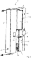
- the Figure 3 and Figure 4 show the sensor device 1 in various isometric representations with further details.
- the sensor device 1 can be fastened to the window frame or a door frame by means of screws through the screw holes 13. Alternatively, it can also be attached using double-sided adhesive tape 30.
- the upper housing part 3 has a recess 31 which receives the optically transparent area 8 when it is placed on the lower housing part 2.
- latching hooks 90 arranged on the lower housing part 2, which, in conjunction with latching recesses 32 arranged in the interior of the upper housing part 3, form a latching connection between the lower housing part 2 and the upper housing part 3, so that the upper housing part 3 is securely fastened to the lower housing part 2, for one Changing the battery but can be easily removed again.
- the Figure 5 shows the sensor device 1 with the lower housing part 2 with the upper housing part 3 removed, the in Figure 5 is not shown. A section of the window sash 20 can also be seen.
- the sensor device 1 emits light 51 via the reflection light barrier through the optically transparent area 8 onto the window sash 20.
- Light 52 reflected by the window sash 20 strikes the light sensor of the reflection light barrier through the optically transparent area 8.
- the window sash 20 is open, no light can be reflected from the latter to the light sensor.
- a reflector element 53 can be attached to the window sash 20 or to a door.
- the reflector element 53 can be designed, for example, in the form of a piece of adhesive tape or another sticker.
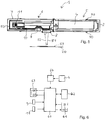
- the Figure 6 shows the internal structure of the sensor device 1 in a schematic representation.
- a microprocessor 60 is provided as the central component.
- the control element 11 and the sabotage contact 9 are connected to this.
- a reflected light barrier 61 is provided as the sensor element of the sensor device 1.
- This has a light source, for example in the form of a light-emitting diode, and a light sensor, for example in the form of a photo transistor, a photo diode or a photo resistor.
- the microprocessor 60 is coupled to a radio data transmission unit 62, for example in the form of the radio module TRX868-TFK-SL.
- the microprocessor 60 is also coupled to output means 63, for example in the form of two light-emitting diodes or a duo-color LED. These are structurally arranged in the housing of the sensor device in such a way that their emitted light can be perceived from the outside through the opening 12.
- the microprocessor 60 and the further components to be supplied with electrical energy are connected to the electrical energy source 4.
- the electrical energy source 4 can be followed by a step-up converter 64, by means of which a low nominal voltage of the electrical energy source 4 is converted into a higher operating voltage of the microprocessor 60 and further components.
- a voltage of 1.5 V provided by the electrical energy source can be converted into a voltage of 3 V by means of step-up converter 64.
- the electronics unit of the sensor device 1 can, for example, by two separate Electrical modules (boards) 54, 55 may be formed, which are arranged side by side in the lower housing part 2.
- the radio data transmission unit can be arranged on the module 55.
- the module 55 is connected to an antenna 50 laid in the antenna receiving channel 10.
- the microprocessor and further components can be arranged on the assembly 54.
- the microprocessor 60 can emit a sabotage signal via the radio data transmission unit 62.
- a learning function of the sensor device 1 can be activated by means of the control element 11. Accordingly, the control element 11 is also to be regarded as a configuration button, with the aid of which the sensor device e.g. can be taught to a specific building monitoring system or an actuator.
Claims (13)
- Dispositif de détection (1) réalisé sous forme de capteur de porte ou de fenêtre d'un système de surveillance de bâtiment et/ou de composant d'un système domotique, qui est conçu pour émettre un signal d'avertissement lorsqu'une porte ou une fenêtre surveillée par le dispositif de détection (1) au moyen d'un élément de détection est ouverte ou est en train d'être ouverte, dans lequel
le dispositif de détection (1) est réalisé sous la forme d'un module compact fonctionnant de manière autonome, comportant un boîtier qui doit être monté sur le cadre de porte d'une porte à surveiller ou sur le cadre de fenêtre d'une fenêtre à surveiller, dans lequel le dispositif de détection (1) comporte en tant qu'élément de détection au moins une barrière lumineuse à réflexion (61) qui est conçue pour émettre de la lumière (51) depuis un côté du boîtier du dispositif de détection (1), dans lequel le boîtier est réalisé en au moins deux parties, avec une partie inférieure de boîtier (2) qui reçoit une unité électronique du dispositif de détection (1) et une partie supérieure de boîtier (3) réalisée sous la forme d'un couvercle, qui peut être placée sur la partie inférieure de boîtier (2), dans lequel le boîtier comporte au moins une zone optiquement transparente (8) destinée à l'émission de la lumière (51) de la source lumineuse de la barrière lumineuse à réflexion (61) et à la réception ses réflexions, caractérisé en ce que le boîtier comporte, en tant qu'autre composant de boîtier, un couvercle intérieur (7) qui recouvre au moins l'unité électronique dans le boîtier, dans lequel le couvercle intérieur (7) est sensiblement ou complètement recouvert par la partie supérieure de boîtier (3) lorsque ce dernier est monté. - Dispositif de détection (1) selon la revendication précédente, caractérisé en ce que le dispositif de détection (1) comporte une unité de transmission de données intégrée dans le boîtier, dans lequel le dispositif de détection (1) est conçu pour la transmission sans fil du signal d'avertissement, lorsqu'une porte ou une fenêtre surveillée par le dispositif de détection (1) au moyen d'un élément de détection est ouverte ou est en train d'être ouverte, au moyen de l'unité de transmission de données à un système de surveillance de bâtiment disposé à distance du dispositif de détection (1).
- Dispositif de détection (1) selon la revendication précédente, caractérisé en ce que l'unité de transmission de données est réalisée sous la forme d'une unité de transmission de données radio (62).
- Dispositif de détection (1) selon la revendication précédente, caractérisé en ce que le dispositif de détection (1) est conçu pour la transmission de données par l'unité de transmission de données radio (62) avec un rapport cyclique limité à une valeur maximale, en particulier un rapport cyclique allant jusqu'à 1%.
- Dispositif de détection (1) selon l'une des revendications précédentes, caractérisé en ce que le dispositif de détection (1) est réalisé sous la forme d'un dispositif de détection (1) commandé par microprocesseur, qui comporte au moins un microprocesseur (60) et dont la fonctionnalité peut être configurée par l'intermédiaire du microprocesseur (60).
- Dispositif de détection (1) selon l'une des revendications précédentes, caractérisé en ce que le dispositif de détection (1) comprend au moins un élément de commande (11) qui peut être actionné par un utilisateur.
- Dispositif de détection (1) selon la revendication précédente, caractérisé en ce qu'un mode d'apprentissage du dispositif de détection (1) peut être activé par l'intermédiaire de l'élément de commande (11), mode dans lequel la fonctionnalité du dispositif de détection (1) peut être configurée.
- Dispositif de détection (1) selon l'une des revendications précédentes, caractérisé en ce que le dispositif de détection (1) comporte une unité d'autosurveillance qui est configurée pour l'autosurveillance du dispositif de détection (1) et est conçue pour délivrer un code d'erreur en cas de détection d'une erreur du dispositif de détection (1).
- Dispositif de détection (1) selon l'une des revendications précédentes, caractérisé en ce que le dispositif de détection (1) est conçu pour l'actionnement pulsé de la source lumineuse de la barrière lumineuse à réflexion (61) et pour vérifier si la lumière (51) reçue par l'intermédiaire du capteur de lumière de la barrière lumineuse à réflexion (61) coïncide sensiblement ou complètement dans le temps avec l'actionnement pulsé de la source lumineuse.
- Dispositif de détection (1) selon la revendication précédente, caractérisé en ce que le dispositif de détection (1) comporte plusieurs parties supérieures de boîtier (3) réalisées sous la forme de couvercles, parmi lesquelles une partie supérieure de boîtier (3) respective doit être reliée à la partie inférieure de boîtier (2) selon le choix de l'utilisateur.
- Dispositif de détection (1) selon l'une des revendications précédentes, caractérisé en ce que la plus grande dimension extérieure du boîtier est au moins cinq fois supérieure à la plus petite dimension extérieure du boîtier.
- Dispositif de détection (1) selon l'une des revendications précédentes, caractérisé en ce que la plus grande dimension extérieure du boîtier est au moins cinq fois supérieure à la deuxième plus petite dimension extérieure du boîtier.
- Dispositif de détection (1) selon l'une des revendications précédentes, caractérisé en ce qu'une source d'énergie électrique (4) du dispositif de détection (1) est disposée dans le boîtier à l'arrière des composants électroniques du dispositif de détection (1) dans la direction de la plus grande dimension extérieure du boîtier.
Applications Claiming Priority (1)
| Application Number | Priority Date | Filing Date | Title |
|---|---|---|---|
| DE202014104195.8U DE202014104195U1 (de) | 2014-09-05 | 2014-09-05 | Sensoreinrichtung |
Publications (2)
| Publication Number | Publication Date |
|---|---|
| EP2993650A1 EP2993650A1 (fr) | 2016-03-09 |
| EP2993650B1 true EP2993650B1 (fr) | 2020-07-29 |
Family
ID=51629372
Family Applications (1)
| Application Number | Title | Priority Date | Filing Date |
|---|---|---|---|
| EP15183478.5A Active EP2993650B1 (fr) | 2014-09-05 | 2015-09-02 | Dispositif de detection |
Country Status (3)
| Country | Link |
|---|---|
| EP (1) | EP2993650B1 (fr) |
| DE (1) | DE202014104195U1 (fr) |
| ES (1) | ES2816775T3 (fr) |
Families Citing this family (4)
| Publication number | Priority date | Publication date | Assignee | Title |
|---|---|---|---|---|
| DE202014104195U1 (de) | 2014-09-05 | 2014-09-17 | Elv Elektronik Ag | Sensoreinrichtung |
| DE102016212821B4 (de) * | 2016-07-13 | 2019-03-07 | Martin Weinläder | Vorrichtung zur Aufnahme von Daten |
| DE202017003794U1 (de) | 2017-07-18 | 2017-08-18 | D:R:O:W: Berlin Verwaltungs UG | System zur Feststellung von Schließ- und Öffnungszuständen von Öffnungen eines Raumes |
| CN113433559B (zh) * | 2021-06-23 | 2022-09-27 | 西南交通大学 | 一种变压器消防安全裕度红外测量装置 |
Citations (26)
| Publication number | Priority date | Publication date | Assignee | Title |
|---|---|---|---|---|
| US4250498A (en) | 1978-05-19 | 1981-02-10 | Erwin Sick Gmbh, Optik-Elektronik | Light barrier receiver |
| DE3119876A1 (de) * | 1981-05-19 | 1982-12-16 | Wilhelm Ruf KG, 8000 München | "infrarot-sende-empfangssystem" |
| US4507654A (en) | 1981-10-30 | 1985-03-26 | A. R. F. Products | Security system with infrared optical position detector |
| US4583082A (en) | 1983-06-09 | 1986-04-15 | Igt | Optical door interlock |
| US5055685A (en) | 1989-12-01 | 1991-10-08 | Optex Co., Ltd. | Infrared detecting apparatus |
| DE4011351A1 (de) | 1990-04-07 | 1991-10-24 | Athmer Fa F | Magnetische tuerdichtung |
| EP0503965A1 (fr) | 1991-03-15 | 1992-09-16 | Pedro Marrero | Système d'alarme |
| JP2588667Y2 (ja) | 1990-12-06 | 1999-01-13 | 株式会社日本アレフ | 反射型フォトセンサ |
| US5912619A (en) * | 1997-12-31 | 1999-06-15 | Wells Fargo Alarm Systems, Inc. | Security system using optical sensors |
| WO2001069287A1 (fr) | 2000-03-13 | 2001-09-20 | Renato Prescendo | Dispositif antivol pour batiments |
| US6411215B1 (en) | 1999-02-19 | 2002-06-25 | J. Mitchell Shnier | Optical methods for detecting the position or state of an object |
| EP0929999B1 (fr) | 1996-09-27 | 2004-03-03 | Jari Ruuttu | Appareil de protection permettant de blinder un appareil electrique contre des conditions environnementales |
| US20050201086A1 (en) | 2004-03-11 | 2005-09-15 | Sick Ag | Protective light barrier |
| EP1271439B1 (fr) | 2001-06-29 | 2006-07-26 | H.H. Heim & Haus Holding GmbH | Dispositif pour surveiller la position de fermeture des portes et des fenêtres |
| US7170060B2 (en) | 2004-02-27 | 2007-01-30 | Optex Co., Ltd. | Passive infrared sensor |
| US7196330B2 (en) | 2004-02-27 | 2007-03-27 | Optex Co., Ltd. | Passive infrared sensor |
| EP1918890A1 (fr) | 2006-11-01 | 2008-05-07 | EFP Vertriebs- und Servicegesellschaft mbH | Dispositif destiné à l'affichage de l'état d'ouverture d'une fenêtre ou d'une porte |
| US7456738B2 (en) | 2005-06-01 | 2008-11-25 | Thermo King Corporation | Transport refrigeration door status sensing device |
| EP2015272A2 (fr) | 2007-07-09 | 2009-01-14 | Robert Bosch GmbH | Détecteur anti-fraude pour capteur de sécurité |
| EP2019377A1 (fr) | 2007-07-25 | 2009-01-28 | Robert Bosch GmbH | Capteur de sécurité optique de décalage pour porte |
| JP2010129005A (ja) | 2008-11-30 | 2010-06-10 | Hochiki Corp | 窓開閉検出装置 |
| US7986232B2 (en) | 2006-08-03 | 2011-07-26 | Tyco Safety Products Canada Ltd. | Method and apparatus for using an infrared reflectivity sensor in a security system |
| DE202013001605U1 (de) | 2013-02-19 | 2013-04-05 | Simon Müller | Vorrichtung zur Überwachung von Gegenständen |
| DE202013006363U1 (de) | 2013-07-16 | 2013-08-02 | Marion Peplies E.K. Dekoprofiltechnik | Plisseevorhang |
| US20140240717A1 (en) | 2013-02-27 | 2014-08-28 | Honeywell International Inc. | Apparatus and Method of Using a Light Conduit in a Position Detector |
| DE202014104195U1 (de) | 2014-09-05 | 2014-09-17 | Elv Elektronik Ag | Sensoreinrichtung |
-
2014
- 2014-09-05 DE DE202014104195.8U patent/DE202014104195U1/de active Active
-
2015
- 2015-09-02 ES ES15183478T patent/ES2816775T3/es active Active
- 2015-09-02 EP EP15183478.5A patent/EP2993650B1/fr active Active
Patent Citations (27)
| Publication number | Priority date | Publication date | Assignee | Title |
|---|---|---|---|---|
| US4250498A (en) | 1978-05-19 | 1981-02-10 | Erwin Sick Gmbh, Optik-Elektronik | Light barrier receiver |
| DE3119876A1 (de) * | 1981-05-19 | 1982-12-16 | Wilhelm Ruf KG, 8000 München | "infrarot-sende-empfangssystem" |
| US4507654A (en) | 1981-10-30 | 1985-03-26 | A. R. F. Products | Security system with infrared optical position detector |
| US4583082A (en) | 1983-06-09 | 1986-04-15 | Igt | Optical door interlock |
| US5055685A (en) | 1989-12-01 | 1991-10-08 | Optex Co., Ltd. | Infrared detecting apparatus |
| DE4011351A1 (de) | 1990-04-07 | 1991-10-24 | Athmer Fa F | Magnetische tuerdichtung |
| JP2588667Y2 (ja) | 1990-12-06 | 1999-01-13 | 株式会社日本アレフ | 反射型フォトセンサ |
| EP0503965A1 (fr) | 1991-03-15 | 1992-09-16 | Pedro Marrero | Système d'alarme |
| EP0929999B1 (fr) | 1996-09-27 | 2004-03-03 | Jari Ruuttu | Appareil de protection permettant de blinder un appareil electrique contre des conditions environnementales |
| US5912619A (en) * | 1997-12-31 | 1999-06-15 | Wells Fargo Alarm Systems, Inc. | Security system using optical sensors |
| US6411215B1 (en) | 1999-02-19 | 2002-06-25 | J. Mitchell Shnier | Optical methods for detecting the position or state of an object |
| WO2001069287A1 (fr) | 2000-03-13 | 2001-09-20 | Renato Prescendo | Dispositif antivol pour batiments |
| EP1271439B1 (fr) | 2001-06-29 | 2006-07-26 | H.H. Heim & Haus Holding GmbH | Dispositif pour surveiller la position de fermeture des portes et des fenêtres |
| US7196330B2 (en) | 2004-02-27 | 2007-03-27 | Optex Co., Ltd. | Passive infrared sensor |
| US7170060B2 (en) | 2004-02-27 | 2007-01-30 | Optex Co., Ltd. | Passive infrared sensor |
| US20050201086A1 (en) | 2004-03-11 | 2005-09-15 | Sick Ag | Protective light barrier |
| US7456738B2 (en) | 2005-06-01 | 2008-11-25 | Thermo King Corporation | Transport refrigeration door status sensing device |
| US7986232B2 (en) | 2006-08-03 | 2011-07-26 | Tyco Safety Products Canada Ltd. | Method and apparatus for using an infrared reflectivity sensor in a security system |
| EP1918890A1 (fr) | 2006-11-01 | 2008-05-07 | EFP Vertriebs- und Servicegesellschaft mbH | Dispositif destiné à l'affichage de l'état d'ouverture d'une fenêtre ou d'une porte |
| EP2015272A2 (fr) | 2007-07-09 | 2009-01-14 | Robert Bosch GmbH | Détecteur anti-fraude pour capteur de sécurité |
| EP2019377A1 (fr) | 2007-07-25 | 2009-01-28 | Robert Bosch GmbH | Capteur de sécurité optique de décalage pour porte |
| JP2010129005A (ja) | 2008-11-30 | 2010-06-10 | Hochiki Corp | 窓開閉検出装置 |
| DE202013001605U1 (de) | 2013-02-19 | 2013-04-05 | Simon Müller | Vorrichtung zur Überwachung von Gegenständen |
| US20140240717A1 (en) | 2013-02-27 | 2014-08-28 | Honeywell International Inc. | Apparatus and Method of Using a Light Conduit in a Position Detector |
| DE202013006363U1 (de) | 2013-07-16 | 2013-08-02 | Marion Peplies E.K. Dekoprofiltechnik | Plisseevorhang |
| DE202014104195U1 (de) | 2014-09-05 | 2014-09-17 | Elv Elektronik Ag | Sensoreinrichtung |
| EP2993650A1 (fr) | 2014-09-05 | 2016-03-09 | ELV Elektronik AG | Dispositif de detection |
Non-Patent Citations (23)
| Title |
|---|
| " Komfort und Energieeinsparung mit HomeMatic®", 1 January 2010, article THOMAS RIEGLER: "20. turen und fenster per funk uberwachen ", pages: 165 - 169, XP055963616 |
| "Digital Proximity Sensor with Interrupt Function", 3 March 2009, article INTERSIL: "Digital Proximity Sensor with Interrupt Function", XP055556251 * |
| ANONYMOUS: " Montage- und Bedienungsanleitung, Funk-Tür- Fensterkontakt HM-Sec-SC", HOMEMATIC, 1 July 2007 (2007-07-01), XP055963669 |
| ANONYMOUS: "Aufwärtswandler – Wikipedia", WIKIPEDIA, 17 August 2014 (2014-08-17), pages 1 - 3, XP055960436, Retrieved from the Internet <URL:https://de.wikipedia.org/wiki/Aufwärtswandler> [retrieved on 20220913] |
| ANONYMOUS: "Booklet of Installation Instructions for SAW Sensors Document No. 466-1622", BOOKLET OF INSTALLATION INSTRUCTIONS FOR SAW SENSORS, 1 January 2000 (2000-01-01), XP055963606, [retrieved on 20220922] |
| ANONYMOUS: "eQ-3 stellt neue smart home-innovation vor ", NEUE PRESSEMITTEILUNGEN, 1 July 2014 (2014-07-01), XP055963728, [retrieved on 20220922] |
| ANONYMOUS: "ESD-Buch", ESD-BUCH, 24 July 2014 (2014-07-24), XP055963684, [retrieved on 20220922] |
| ANONYMOUS: "Funk-Heizungssteuerung Einführung und Übersicht", MAX!, 1 March 2009 (2009-03-01), pages 1 - 34, XP055960343, Retrieved from the Internet <URL:https://www.eq-3.de/Downloads/eq3/download%20bereich/handbuecher/MAX-Systemuebersicht.pdf> [retrieved on 20220913] |
| ANONYMOUS: "Funk-Tür-Fenster-Melder ELV Montage-und Bedienungsanleitung", ELV, 1 March 2009 (2009-03-01), pages 1 - 16, XP055960349, [retrieved on 20220913] |
| ANONYMOUS: "HM-SEC-SCO BEDIENUNGSANLEITUNG", HM-SEC-SCO BEDIENUNGSANLEITUNG, 1 June 2014 (2014-06-01), pages 1 - 60, XP055960282 |
| ANONYMOUS: "ITI SAW Door/Window Sensor Instalation instructions", ITI PART, 1 March 2002 (2002-03-01), XP055963609, [retrieved on 20220922] |
| ANONYMOUS: "MAX! Fensterkontakt bedienungsanleitung", EQ-3, 1 December 2012 (2012-12-01), pages 1 - 28, XP055960317 |
| ANONYMOUS: "Optischer HomeMatic®- Tür-/Fensterkontakt ", ELV.DE, 1 August 2014 (2014-08-01), XP055963600 |
| ANONYMOUS: "Sorgt für Spannung - Step-up-Wandler SUW-TPS", ELW, 17 August 2014 (2014-08-17), pages 1 - 4, XP055960444 |
| ANONYMOUS: "wireless sensors security anywhere interlogix", INTERLOGIX, 1 June 2014 (2014-06-01), pages 1 - 12, XP055960401 |
| DATENBLATT -20130703-V1_3 SENSOR SMCDW02-Z, 2013, XP55960404 |
| ELV JOURNAL, 30 July 2014 (2014-07-30), XP055963722 |
| EQ-3 MAXI WINDOW SENSOR ANLEITUNG, April 2012 (2012-04-01) |
| EQ-3: "Montage-und Inbetriebnahmeanleitung Installation and Operating Manual Funk-Tür-/Fensterkontakt, optisch Wireless Door/Window Sensor, optical HM-Sec-SCo", 1 June 2014 (2014-06-01), XP055663516, Retrieved from the Internet <URL:http://web.archive.org/web/20140809110952if_/http://www.elv-downloads.de:80/Assets/Produkte/13/1302/130297/Downloads/130297_fensterkontakt_optisch_um.pdf> [retrieved on 20200130] * |
| FENSTERKONTAKT MAX !: " MAX! Fensterkontakt", BEDIENUNGSANLEITUNG OPERATING MANUAL, 1 April 2012 (2012-04-01), XP055963603, [retrieved on 20220922] |
| HUANG JEMMEY, ET AL: "Infrared Proxomity Detection with PSoC AN50956", CYPRESS PREFORM, 4 September 2014 (2014-09-04), pages 1 - 14, XP055960429 |
| JEMMEY HUANG ET AL: "Innfrared Proximity Detection with PSoC", CYPRESS, 13 January 2013 (2013-01-13), XP055556109 * |
| VISHAY SEMICONDUCTORS: "Fully Integrated Proximity Sensor with Infrared Emitter, I2C Interface and Interrupt Function", 13 August 2014 (2014-08-13), XP055556098, Retrieved from the Internet <URL:www.vishay.com> [retrieved on 20190213] * |
Also Published As
| Publication number | Publication date |
|---|---|
| ES2816775T3 (es) | 2021-04-05 |
| DE202014104195U1 (de) | 2014-09-17 |
| EP2993650A1 (fr) | 2016-03-09 |
Similar Documents
| Publication | Publication Date | Title |
|---|---|---|
| EP2993650B1 (fr) | Dispositif de detection | |
| DE102006013027B4 (de) | Griffelement | |
| DE202019005937U1 (de) | Sicherheitsschalter | |
| WO2015144362A1 (fr) | Dispositif pour une poignée d'actionnement, poignée d'actionnement et procédé servant à la transmission sans fil d'un signal produit avec une autonomie d'énergie | |
| DE10059582A1 (de) | Überwachungseinrichtung für ein Fenster, eine Tür oder dergleichen | |
| DE202005000784U1 (de) | Vorrichtung zum Erfassen der Position einer Betätigungshandhabe | |
| EP1785962A2 (fr) | Adaptateur radio pour poignée de fenêtre ou de porte | |
| DE102006017654B4 (de) | Funk-Adapter mit magnetbetätigten Reedkontakten für einen Fenster- oder Türgriff | |
| EP2383409B1 (fr) | Dispositif de fermeture avec un dispositif de détection d'état | |
| DE102010056352A1 (de) | Schließanlage | |
| DE102016002606A1 (de) | Vorrichtung zur Erfassung der Position eines Fenster- oder Türgriffs | |
| EP0617500A1 (fr) | Dispositif de transmission de données sans fil | |
| DE102015225480A1 (de) | Kontaktschalter, Öffnungs- und/oder Schließvorrichtung und Öffnungs- und/oder Schließsystem | |
| EP3035075B1 (fr) | Detecteur de mouvement configurable | |
| DE102014102564B4 (de) | Absolutwert-Singleturn-Drehgeber mit auswählbarer Multiturn-Funktion | |
| EP1400936B1 (fr) | Dispositif de surveillance et de sécurité pour portes, fenêtres et similaires | |
| DE202012003659U1 (de) | Detektionsvorrichtung | |
| EP2453426B1 (fr) | Capteur de surveillance doté d'un autotest | |
| EP2717233B1 (fr) | Dispositif d'identification d'un chat à des fins de commande d'une chatière électronique | |
| EP2998470B1 (fr) | Armature pour une porte de bâtiment | |
| DE10118120C1 (de) | Beleuchtungssystem für Handhaben | |
| EP2362040B1 (fr) | Dispositif de fermeture | |
| DE102015005639A1 (de) | Kommunikationseinrichtung mit einem stationären Lesegerät, sowie ein Verfahren zum Betrieb einer derartigen Kommunikationseinrichtung | |
| EP2998491A1 (fr) | Dispositif de sécurité d'issue de secours | |
| EP0955615B1 (fr) | Dispositif anti-effraction utilisant un système d'alarme avec volet roulant |
Legal Events
| Date | Code | Title | Description |
|---|---|---|---|
| PUAI | Public reference made under article 153(3) epc to a published international application that has entered the european phase |
Free format text: ORIGINAL CODE: 0009012 |
|
| AK | Designated contracting states |
Kind code of ref document: A1 Designated state(s): AL AT BE BG CH CY CZ DE DK EE ES FI FR GB GR HR HU IE IS IT LI LT LU LV MC MK MT NL NO PL PT RO RS SE SI SK SM TR |
|
| AX | Request for extension of the european patent |
Extension state: BA ME |
|
| 17P | Request for examination filed |
Effective date: 20160720 |
|
| RBV | Designated contracting states (corrected) |
Designated state(s): AL AT BE BG CH CY CZ DE DK EE ES FI FR GB GR HR HU IE IS IT LI LT LU LV MC MK MT NL NO PL PT RO RS SE SI SK SM TR |
|
| STAA | Information on the status of an ep patent application or granted ep patent |
Free format text: STATUS: EXAMINATION IS IN PROGRESS |
|
| 17Q | First examination report despatched |
Effective date: 20170511 |
|
| TPAC | Observations filed by third parties |
Free format text: ORIGINAL CODE: EPIDOSNTIPA |
|
| TPAA | Information related to observations by third parties modified |
Free format text: ORIGINAL CODE: EPIDOSCTIPA |
|
| TPAC | Observations filed by third parties |
Free format text: ORIGINAL CODE: EPIDOSNTIPA |
|
| TPAC | Observations filed by third parties |
Free format text: ORIGINAL CODE: EPIDOSNTIPA |
|
| GRAP | Despatch of communication of intention to grant a patent |
Free format text: ORIGINAL CODE: EPIDOSNIGR1 |
|
| STAA | Information on the status of an ep patent application or granted ep patent |
Free format text: STATUS: GRANT OF PATENT IS INTENDED |
|
| RIC1 | Information provided on ipc code assigned before grant |
Ipc: G08B 13/184 20060101ALI20200130BHEP Ipc: G08B 13/08 20060101AFI20200130BHEP Ipc: G08B 25/10 20060101ALI20200130BHEP |
|
| RIC1 | Information provided on ipc code assigned before grant |
Ipc: G08B 29/04 20060101ALI20200206BHEP Ipc: G08B 13/184 20060101ALI20200206BHEP Ipc: G08B 25/10 20060101ALI20200206BHEP Ipc: G08B 13/08 20060101AFI20200206BHEP |
|
| INTG | Intention to grant announced |
Effective date: 20200226 |
|
| GRAS | Grant fee paid |
Free format text: ORIGINAL CODE: EPIDOSNIGR3 |
|
| GRAA | (expected) grant |
Free format text: ORIGINAL CODE: 0009210 |
|
| STAA | Information on the status of an ep patent application or granted ep patent |
Free format text: STATUS: THE PATENT HAS BEEN GRANTED |
|
| AK | Designated contracting states |
Kind code of ref document: B1 Designated state(s): AL AT BE BG CH CY CZ DE DK EE ES FI FR GB GR HR HU IE IS IT LI LT LU LV MC MK MT NL NO PL PT RO RS SE SI SK SM TR |
|
| REG | Reference to a national code |
Ref country code: CH Ref legal event code: EP |
|
| REG | Reference to a national code |
Ref country code: AT Ref legal event code: REF Ref document number: 1296704 Country of ref document: AT Kind code of ref document: T Effective date: 20200815 |
|
| REG | Reference to a national code |
Ref country code: IE Ref legal event code: FG4D Free format text: LANGUAGE OF EP DOCUMENT: GERMAN |
|
| REG | Reference to a national code |
Ref country code: DE Ref legal event code: R096 Ref document number: 502015013094 Country of ref document: DE |
|
| REG | Reference to a national code |
Ref country code: DE Ref legal event code: R026 Ref document number: 502015013094 Country of ref document: DE |
|
| PLBI | Opposition filed |
Free format text: ORIGINAL CODE: 0009260 |
|
| REG | Reference to a national code |
Ref country code: FI Ref legal event code: MDE Opponent name: EUROTRONIC TECHNOLOGY GMBH |
|
| 26 | Opposition filed |
Opponent name: EUROTRONIC TECHNOLOGY GMBH Effective date: 20200904 |
|
| REG | Reference to a national code |
Ref country code: LT Ref legal event code: MG4D |
|
| REG | Reference to a national code |
Ref country code: NL Ref legal event code: MP Effective date: 20200729 |
|
| PG25 | Lapsed in a contracting state [announced via postgrant information from national office to epo] |
Ref country code: GR Free format text: LAPSE BECAUSE OF FAILURE TO SUBMIT A TRANSLATION OF THE DESCRIPTION OR TO PAY THE FEE WITHIN THE PRESCRIBED TIME-LIMIT Effective date: 20201030 Ref country code: BG Free format text: LAPSE BECAUSE OF FAILURE TO SUBMIT A TRANSLATION OF THE DESCRIPTION OR TO PAY THE FEE WITHIN THE PRESCRIBED TIME-LIMIT Effective date: 20201029 Ref country code: HR Free format text: LAPSE BECAUSE OF FAILURE TO SUBMIT A TRANSLATION OF THE DESCRIPTION OR TO PAY THE FEE WITHIN THE PRESCRIBED TIME-LIMIT Effective date: 20200729 Ref country code: NO Free format text: LAPSE BECAUSE OF FAILURE TO SUBMIT A TRANSLATION OF THE DESCRIPTION OR TO PAY THE FEE WITHIN THE PRESCRIBED TIME-LIMIT Effective date: 20201029 Ref country code: LT Free format text: LAPSE BECAUSE OF FAILURE TO SUBMIT A TRANSLATION OF THE DESCRIPTION OR TO PAY THE FEE WITHIN THE PRESCRIBED TIME-LIMIT Effective date: 20200729 Ref country code: FI Free format text: LAPSE BECAUSE OF FAILURE TO SUBMIT A TRANSLATION OF THE DESCRIPTION OR TO PAY THE FEE WITHIN THE PRESCRIBED TIME-LIMIT Effective date: 20200729 Ref country code: PT Free format text: LAPSE BECAUSE OF FAILURE TO SUBMIT A TRANSLATION OF THE DESCRIPTION OR TO PAY THE FEE WITHIN THE PRESCRIBED TIME-LIMIT Effective date: 20201130 Ref country code: SE Free format text: LAPSE BECAUSE OF FAILURE TO SUBMIT A TRANSLATION OF THE DESCRIPTION OR TO PAY THE FEE WITHIN THE PRESCRIBED TIME-LIMIT Effective date: 20200729 |
|
| PG25 | Lapsed in a contracting state [announced via postgrant information from national office to epo] |
Ref country code: RS Free format text: LAPSE BECAUSE OF FAILURE TO SUBMIT A TRANSLATION OF THE DESCRIPTION OR TO PAY THE FEE WITHIN THE PRESCRIBED TIME-LIMIT Effective date: 20200729 Ref country code: LV Free format text: LAPSE BECAUSE OF FAILURE TO SUBMIT A TRANSLATION OF THE DESCRIPTION OR TO PAY THE FEE WITHIN THE PRESCRIBED TIME-LIMIT Effective date: 20200729 Ref country code: PL Free format text: LAPSE BECAUSE OF FAILURE TO SUBMIT A TRANSLATION OF THE DESCRIPTION OR TO PAY THE FEE WITHIN THE PRESCRIBED TIME-LIMIT Effective date: 20200729 Ref country code: IS Free format text: LAPSE BECAUSE OF FAILURE TO SUBMIT A TRANSLATION OF THE DESCRIPTION OR TO PAY THE FEE WITHIN THE PRESCRIBED TIME-LIMIT Effective date: 20201129 |
|
| PG25 | Lapsed in a contracting state [announced via postgrant information from national office to epo] |
Ref country code: NL Free format text: LAPSE BECAUSE OF FAILURE TO SUBMIT A TRANSLATION OF THE DESCRIPTION OR TO PAY THE FEE WITHIN THE PRESCRIBED TIME-LIMIT Effective date: 20200729 |
|
| REG | Reference to a national code |
Ref country code: ES Ref legal event code: FG2A Ref document number: 2816775 Country of ref document: ES Kind code of ref document: T3 Effective date: 20210405 |
|
| PLBI | Opposition filed |
Free format text: ORIGINAL CODE: 0009260 |
|
| PG25 | Lapsed in a contracting state [announced via postgrant information from national office to epo] |
Ref country code: MC Free format text: LAPSE BECAUSE OF FAILURE TO SUBMIT A TRANSLATION OF THE DESCRIPTION OR TO PAY THE FEE WITHIN THE PRESCRIBED TIME-LIMIT Effective date: 20200729 Ref country code: SM Free format text: LAPSE BECAUSE OF FAILURE TO SUBMIT A TRANSLATION OF THE DESCRIPTION OR TO PAY THE FEE WITHIN THE PRESCRIBED TIME-LIMIT Effective date: 20200729 Ref country code: RO Free format text: LAPSE BECAUSE OF FAILURE TO SUBMIT A TRANSLATION OF THE DESCRIPTION OR TO PAY THE FEE WITHIN THE PRESCRIBED TIME-LIMIT Effective date: 20200729 Ref country code: EE Free format text: LAPSE BECAUSE OF FAILURE TO SUBMIT A TRANSLATION OF THE DESCRIPTION OR TO PAY THE FEE WITHIN THE PRESCRIBED TIME-LIMIT Effective date: 20200729 Ref country code: DK Free format text: LAPSE BECAUSE OF FAILURE TO SUBMIT A TRANSLATION OF THE DESCRIPTION OR TO PAY THE FEE WITHIN THE PRESCRIBED TIME-LIMIT Effective date: 20200729 Ref country code: CZ Free format text: LAPSE BECAUSE OF FAILURE TO SUBMIT A TRANSLATION OF THE DESCRIPTION OR TO PAY THE FEE WITHIN THE PRESCRIBED TIME-LIMIT Effective date: 20200729 |
|
| REG | Reference to a national code |
Ref country code: CH Ref legal event code: PL |
|
| PLAX | Notice of opposition and request to file observation + time limit sent |
Free format text: ORIGINAL CODE: EPIDOSNOBS2 |
|
| 26 | Opposition filed |
Opponent name: TELEKOM DEUTSCHLAND GMBH Effective date: 20210421 |
|
| PG25 | Lapsed in a contracting state [announced via postgrant information from national office to epo] |
Ref country code: AL Free format text: LAPSE BECAUSE OF FAILURE TO SUBMIT A TRANSLATION OF THE DESCRIPTION OR TO PAY THE FEE WITHIN THE PRESCRIBED TIME-LIMIT Effective date: 20200729 |
|
| REG | Reference to a national code |
Ref country code: BE Ref legal event code: MM Effective date: 20200930 |
|
| GBPC | Gb: european patent ceased through non-payment of renewal fee |
Effective date: 20201029 |
|
| PG25 | Lapsed in a contracting state [announced via postgrant information from national office to epo] |
Ref country code: SK Free format text: LAPSE BECAUSE OF FAILURE TO SUBMIT A TRANSLATION OF THE DESCRIPTION OR TO PAY THE FEE WITHIN THE PRESCRIBED TIME-LIMIT Effective date: 20200729 Ref country code: LU Free format text: LAPSE BECAUSE OF NON-PAYMENT OF DUE FEES Effective date: 20200902 |
|
| PG25 | Lapsed in a contracting state [announced via postgrant information from national office to epo] |
Ref country code: IE Free format text: LAPSE BECAUSE OF NON-PAYMENT OF DUE FEES Effective date: 20200902 Ref country code: LI Free format text: LAPSE BECAUSE OF NON-PAYMENT OF DUE FEES Effective date: 20200930 Ref country code: GB Free format text: LAPSE BECAUSE OF NON-PAYMENT OF DUE FEES Effective date: 20201029 Ref country code: SI Free format text: LAPSE BECAUSE OF FAILURE TO SUBMIT A TRANSLATION OF THE DESCRIPTION OR TO PAY THE FEE WITHIN THE PRESCRIBED TIME-LIMIT Effective date: 20200729 Ref country code: BE Free format text: LAPSE BECAUSE OF NON-PAYMENT OF DUE FEES Effective date: 20200930 Ref country code: CH Free format text: LAPSE BECAUSE OF NON-PAYMENT OF DUE FEES Effective date: 20200930 |
|
| PLBB | Reply of patent proprietor to notice(s) of opposition received |
Free format text: ORIGINAL CODE: EPIDOSNOBS3 |
|
| REG | Reference to a national code |
Ref country code: AT Ref legal event code: MM01 Ref document number: 1296704 Country of ref document: AT Kind code of ref document: T Effective date: 20200902 |
|
| PG25 | Lapsed in a contracting state [announced via postgrant information from national office to epo] |
Ref country code: AT Free format text: LAPSE BECAUSE OF NON-PAYMENT OF DUE FEES Effective date: 20200902 |
|
| PG25 | Lapsed in a contracting state [announced via postgrant information from national office to epo] |
Ref country code: TR Free format text: LAPSE BECAUSE OF FAILURE TO SUBMIT A TRANSLATION OF THE DESCRIPTION OR TO PAY THE FEE WITHIN THE PRESCRIBED TIME-LIMIT Effective date: 20200729 Ref country code: MT Free format text: LAPSE BECAUSE OF FAILURE TO SUBMIT A TRANSLATION OF THE DESCRIPTION OR TO PAY THE FEE WITHIN THE PRESCRIBED TIME-LIMIT Effective date: 20200729 Ref country code: CY Free format text: LAPSE BECAUSE OF FAILURE TO SUBMIT A TRANSLATION OF THE DESCRIPTION OR TO PAY THE FEE WITHIN THE PRESCRIBED TIME-LIMIT Effective date: 20200729 |
|
| PG25 | Lapsed in a contracting state [announced via postgrant information from national office to epo] |
Ref country code: MK Free format text: LAPSE BECAUSE OF FAILURE TO SUBMIT A TRANSLATION OF THE DESCRIPTION OR TO PAY THE FEE WITHIN THE PRESCRIBED TIME-LIMIT Effective date: 20200729 |
|
| APBM | Appeal reference recorded |
Free format text: ORIGINAL CODE: EPIDOSNREFNO |
|
| APBP | Date of receipt of notice of appeal recorded |
Free format text: ORIGINAL CODE: EPIDOSNNOA2O |
|
| APAH | Appeal reference modified |
Free format text: ORIGINAL CODE: EPIDOSCREFNO |
|
| APAW | Appeal reference deleted |
Free format text: ORIGINAL CODE: EPIDOSDREFNO |
|
| APBM | Appeal reference recorded |
Free format text: ORIGINAL CODE: EPIDOSNREFNO |
|
| APBP | Date of receipt of notice of appeal recorded |
Free format text: ORIGINAL CODE: EPIDOSNNOA2O |
|
| PLAB | Opposition data, opponent's data or that of the opponent's representative modified |
Free format text: ORIGINAL CODE: 0009299OPPO |
|
| APAH | Appeal reference modified |
Free format text: ORIGINAL CODE: EPIDOSCREFNO |
|
| R26 | Opposition filed (corrected) |
Opponent name: TELEKOM DEUTSCHLAND GMBH Effective date: 20210421 |
|
| REG | Reference to a national code |
Ref country code: DE Ref legal event code: R082 Ref document number: 502015013094 Country of ref document: DE Representative=s name: MEISSNER BOLTE PATENTANWAELTE RECHTSANWAELTE P, DE |
|
| APBQ | Date of receipt of statement of grounds of appeal recorded |
Free format text: ORIGINAL CODE: EPIDOSNNOA3O |
|
| APBQ | Date of receipt of statement of grounds of appeal recorded |
Free format text: ORIGINAL CODE: EPIDOSNNOA3O |
|
| P01 | Opt-out of the competence of the unified patent court (upc) registered |
Effective date: 20230517 |
|
| PGFP | Annual fee paid to national office [announced via postgrant information from national office to epo] |
Ref country code: FR Payment date: 20230918 Year of fee payment: 9 Ref country code: DE Payment date: 20230927 Year of fee payment: 9 |
|
| PGFP | Annual fee paid to national office [announced via postgrant information from national office to epo] |
Ref country code: ES Payment date: 20231019 Year of fee payment: 9 |
|
| PGFP | Annual fee paid to national office [announced via postgrant information from national office to epo] |
Ref country code: IT Payment date: 20230929 Year of fee payment: 9 |