EP2993650B1 - Sensor device - Google Patents
Sensor device Download PDFInfo
- Publication number
- EP2993650B1 EP2993650B1 EP15183478.5A EP15183478A EP2993650B1 EP 2993650 B1 EP2993650 B1 EP 2993650B1 EP 15183478 A EP15183478 A EP 15183478A EP 2993650 B1 EP2993650 B1 EP 2993650B1
- Authority
- EP
- European Patent Office
- Prior art keywords
- sensor device
- housing
- sensor
- light
- embodied
- Prior art date
- Legal status (The legal status is an assumption and is not a legal conclusion. Google has not performed a legal analysis and makes no representation as to the accuracy of the status listed.)
- Active
Links
- 230000005540 biological transmission Effects 0.000 claims description 24
- 230000004888 barrier function Effects 0.000 claims description 23
- 238000012544 monitoring process Methods 0.000 claims description 23
- 238000009434 installation Methods 0.000 claims description 3
- 230000008901 benefit Effects 0.000 description 32
- 230000011514 reflex Effects 0.000 description 12
- 230000006870 function Effects 0.000 description 6
- 230000003287 optical effect Effects 0.000 description 6
- 230000008859 change Effects 0.000 description 3
- 239000002390 adhesive tape Substances 0.000 description 2
- 238000004140 cleaning Methods 0.000 description 2
- 238000004891 communication Methods 0.000 description 2
- 230000007613 environmental effect Effects 0.000 description 2
- 239000012780 transparent material Substances 0.000 description 2
- 235000014676 Phragmites communis Nutrition 0.000 description 1
- 239000011358 absorbing material Substances 0.000 description 1
- 230000004913 activation Effects 0.000 description 1
- 239000003086 colorant Substances 0.000 description 1
- 238000001514 detection method Methods 0.000 description 1
- 238000010586 diagram Methods 0.000 description 1
- 238000005516 engineering process Methods 0.000 description 1
- 230000036039 immunity Effects 0.000 description 1
- 229910001172 neodymium magnet Inorganic materials 0.000 description 1
- 230000000007 visual effect Effects 0.000 description 1
Images


Classifications
-
- G—PHYSICS
- G08—SIGNALLING
- G08B—SIGNALLING OR CALLING SYSTEMS; ORDER TELEGRAPHS; ALARM SYSTEMS
- G08B13/00—Burglar, theft or intruder alarms
- G08B13/02—Mechanical actuation
- G08B13/08—Mechanical actuation by opening, e.g. of door, of window, of drawer, of shutter, of curtain, of blind
-
- G—PHYSICS
- G08—SIGNALLING
- G08B—SIGNALLING OR CALLING SYSTEMS; ORDER TELEGRAPHS; ALARM SYSTEMS
- G08B25/00—Alarm systems in which the location of the alarm condition is signalled to a central station, e.g. fire or police telegraphic systems
- G08B25/01—Alarm systems in which the location of the alarm condition is signalled to a central station, e.g. fire or police telegraphic systems characterised by the transmission medium
- G08B25/10—Alarm systems in which the location of the alarm condition is signalled to a central station, e.g. fire or police telegraphic systems characterised by the transmission medium using wireless transmission systems
-
- G—PHYSICS
- G08—SIGNALLING
- G08B—SIGNALLING OR CALLING SYSTEMS; ORDER TELEGRAPHS; ALARM SYSTEMS
- G08B29/00—Checking or monitoring of signalling or alarm systems; Prevention or correction of operating errors, e.g. preventing unauthorised operation
- G08B29/02—Monitoring continuously signalling or alarm systems
- G08B29/04—Monitoring of the detection circuits
Definitions
- the invention relates to a sensor device designed as a door or window sensor of a building monitoring system or as a component of a home automation system.
- the invention relates to the field of building surveillance by a surveillance system, e.g. in the form of an alarm system.
- a surveillance system e.g. in the form of an alarm system.
- door or window contacts are usually used, which can detect an open door or an open window by mechanical sensing by means of a switch contact or by magnetically operated reed contacts.
- Magnetically operating door or window contacts in particular are widespread, but have the disadvantage that two components always have to be installed, namely the door or window contact and a magnet interacting with it. This involves a certain amount of assembly work.
- the magnet must be precisely aligned. It can also happen that the magnet is removed during cleaning, damaged or incorrectly replaced after it has been removed.
- the frequently used neodymium magnets are expensive and, from an ecological point of view, questionable because they are rare earths.
- a device for monitoring objects is known.
- a security system with an infrared optical position detector is known.
- EP 2 015 272 A2 is a tamper detector known for a safety sensor.
- WO 01/69287 A1 an anti-theft device for buildings is known.
- a pre-model of the sensor device is known from an operating manual from the company eQ-3 (XP055663516).
- the invention is therefore based on the object of specifying an improved door / window contact or, generally speaking, a corresponding sensor device which does not have such disadvantages.
- a sensor device designed as a door or window sensor of a building monitoring system according to claim 1.
- the warning signal accordingly indicates that the door or window monitored by the sensor device is open or is being opened.
- the building monitoring system can then e.g. use for triggering an alarm, for storage as part of a data logger function and / or for forwarding to the police or to a security service.
- the invention has the advantage that only one component has to be assembled, namely the sensor device according to the invention. Additional parts, such as the magnet, are no longer required and therefore do not have to be installed.
- the function and the monitoring security of the building monitoring system are improved with the sensor device according to the invention, because instead of the previous magnetic monitoring principle, an optical monitoring principle is now proposed through the use of a reflex light barrier, also called reflex coupler.
- the novel monitoring principle of the sensor device according to the invention is less susceptible to installation tolerances and in particular less susceptible to subsequent influences, for example due to cleaning work, since it cannot happen that the additional magnet which would otherwise be necessary is lost, since it is not necessary here.
- a reflex light barrier typically has at least one light source, e.g. in the form of an LED, and at least one light sensor, e.g. in the form of a photo transistor, a photo diode or a photo resistor.
- the sensor device has a data transmission unit integrated in the housing, the sensor device for wireless transmission of the warning signal when a door or a window monitored by the sensor device is opened or opened by means of the sensor element Data transmission unit to a building surveillance system arranged away from the sensor device.
- the data transmission unit can e.g. be designed as an optical data transmission unit, e.g. to transmit the warning signal or other data via light signals with visible or invisible light, e.g. using infrared light.
- the data transmission unit is designed as a radio data transmission unit. This has the advantage that even greater distances or distances to the building monitoring system, for which there is no optical contact between the sensor device and the building monitoring system, can be covered during data transmission.
- standardized radio protocols and radio frequencies can be used, e.g. 868.3 MHz with a SRD Category 2 receiver.
- the sensor device for data transmission via the radio data transmission unit is set up with a duty cycle limited to a maximum value, in particular a duty cycle of up to 1%.
- the duty cycle is understood to mean the maximum transmission time of a sensor device in a predetermined time period, for example in one hour.
- a sensor device may therefore only transmit in the predetermined time period over a total of 1% of this time period, thus for 36 seconds over a period of one hour.
- a sensor device may no longer transmit until the predetermined period has expired and a new period begins.
- the radio data transmission unit has an antenna which is laid in the housing, in particular angled several times. This has the advantage that the antenna is optically covered and does not interfere.
- an antenna receiving channel can be provided in the housing, in which the antenna is to be laid. This has the advantage that the antenna is always installed at a defined point and cannot leave this position.
- the reflected light barrier is designed as an infrared reflected light barrier. This has the advantage that the light emitted by the sensor device is not perceived by people. This also improves the immunity to interference of the sensor device compared to visible light.
- the sensor device is designed as a microprocessor-controlled sensor device which has at least one microprocessor and its functionality can be configured via the microprocessor. This has the advantage that the sensor device can be used very flexibly and, due to its configurability, can be adapted to different applications.
- a microprocessor is understood to mean any electronic component which has a microprocessor, is designed as such or has such a function, in particular microcontrollers, microcomputers, FPGAs, ASICs.
- the sensor device has at least one control element that can be actuated by a user.
- the control element can e.g. as a button or as a contactless contact, e.g. be designed as a magnetically actuated contact.
- a teach-in mode of the sensor device can be activated via the control element, in which the functionality of the sensor device can be configured.
- the sensor device can also have one or more output elements, such as Light sources or other output units via which the user can be given feedback on the operating status of the sensor device.
- output elements such as Light sources or other output units via which the user can be given feedback on the operating status of the sensor device.
- the sensor device has at least one tamper contact, by means of which it can be detected whether the housing of the sensor device has been opened or removed.
- This has the advantage that any manipulation of the sensor device does not remain undetected, but can be recognized by the sensor device through the tamper contact. Is through the sabotage contact Detects that the housing of the sensor device has been opened or removed, the sensor device can emit a sabotage signal which, for example, is transmitted to the building monitoring system like the warning signal and processed there accordingly, for example to generate an alarm, for data logging and / or for information the police or other security forces.
- the sensor device has a self-monitoring unit which is set up for self-monitoring of the sensor device and is set up to output an error code when a fault is detected in the sensor device.
- the sensor device can e.g. the function of the reflex light barrier can be monitored, e.g. as to whether the light source is still functional.
- the data transmission unit can also be monitored for correct functioning.
- the status of an electrical energy source of the sensor device can be monitored, i. H. e.g. information about an undervoltage or a weak battery is output.
- the error codes can e.g. are output by means of a light source of the sensor device in the form of a blink code.
- the sensor device is set up for pulsed actuation of the light source of the reflective light barrier and for checking whether the light received via the light sensor of the reflective light barrier coincides substantially or completely with the pulsed actuation of the light source.
- Activation of the light source is understood to mean switching on the light source.
- the pulsed actuation saves electrical energy compared to a constant actuation of the light source. This is of great advantage in particular in the case of an energy source integrated in the housing of the sensor device, for example in the form of an accumulator or a battery.
- this can be used to carry out a security check as to whether the light received by the light sensor matches the light emitted by the light source, at least in terms of time. If this is not the case, an error can likewise be recognized and output by the sensor device.
- the sensor device is configured to modulate the light emitted by the light source of the reflex light barrier according to a predetermined code and to check whether the light received via the light sensor of the reflex light barrier has a modulation with a coding that corresponds to the predetermined code .
- a pulse code can be used as a predetermined code, in particular a code with varying encryption.
- the sensor device is set up to emit the warning signal when the light received by the light sensor of the reflex light barrier exceeds a certain threshold value when the light sensor of the reflex light barrier is essentially or completely inactive.
- This has the advantage that an additional detection of an open window or an open door is possible.
- the light source of the reflex light barrier is not switched on. Nevertheless, the light received by the light sensor is evaluated in these phases, ie the signals emitted by the light sensor. If these signals indicate that a relatively large amount of light is being received by the light sensor, so that a certain threshold value has been exceeded, it can be assumed that a monitored window is open into the sunlight seems, or that another external light source hits the light sensor.
- the sensor device has an electrical energy source for the electrical energy supply of the electronic components of the sensor device.
- the sensor device is also self-sufficient with regard to the energy supply and does not require any external electrical supply lines for the energy supply. This further simplifies the assembly of the sensor device.
- the electrical energy source can e.g. be designed as a battery or accumulator, or as a solar cell or a combination thereof. Accumulators are known to be rechargeable, batteries are not.
- the senor device is set up to operate with a single-cell battery as an electrical energy source.
- a battery change is simplified because only a single battery cell has to be replaced.
- the space required for the electrical energy source is relatively small, because e.g. a slim battery can be used, e.g. in the form of an AA or AAA cell.
- the sensor device has an electrical energy source integrated in the housing with a downstream step-up converter for the electrical energy supply of the electronic components of the sensor device.
- a downstream step-up converter for the electrical energy supply of the electronic components of the sensor device.
- the step-up converter is arranged in the housing with respect to the radio data transmission unit and / or its antenna in such a way that interference from the step-up converter in the base point of the antenna is minimized.
- the housing is formed at least in two parts with a lower housing part which receives an electronics unit of the sensor device and an upper housing part which is designed in the form of a cover cap and which can be placed on the lower housing part, the housing at least one optically transparent Area for emitting the light of the light source of the reflex light barrier and receiving its reflections.
- the housing can also be easily assembled and disassembled by the user, e.g. to change the battery.
- the window or door can be easily monitored by the sensor device through the closed housing by providing the optically transparent area there, e.g. in the form of a transparent area.
- Such a closed housing has the advantage that the components arranged therein are well protected against environmental influences.
- the sensor device has a plurality of upper housing parts in the form of cover caps, of which one upper housing part is to be connected to the lower housing part at the user's choice.
- This has the advantage that several cover caps can be provided for different applications, for example cover caps in different colors, in order to adapt the external appearance of the sensor device to the interior of a room or the color of a door or a window on which the sensor device is to be mounted.
- the housing as a further housing component, has an inner cover cap, which at least covers the electronics unit in the housing, the inner cover cap being substantially or completely covered by this when the upper housing part is attached.
- the inner cover cap can also be used for guiding and holding the antenna of the radio data transmission unit by providing a corresponding antenna receiving channel for laying the antenna.
- the inner cover cap is optically transparent, e.g. transparent. This has the advantage that the reflex light barrier can still perform its optical monitoring function through the inner cover cap.
- the housing has a battery compartment into which a replaceable battery can be used as the electrical energy source of the sensor device. This has the advantage that the battery can be easily replaced by the user.
- the housing has an essentially or completely cuboid outer contour. This has the advantage that the sensor device is optically good adapts to normal door and window sashes and is relatively inconspicuous.
- the largest external dimension (e.g. the length) of the housing is at least five times as large as the smallest external dimension (e.g. the width or height) of the housing.
- the largest outer dimension of the housing is at least five times as large as the second smallest outer dimension of the housing.
- an electrical energy source of the sensor device is arranged in the housing in the direction of the largest external dimension of the housing behind the electronic components of the sensor device.
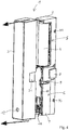
- the Figure 1 shows a top view of a sensor device 1 which has a housing formed from a lower housing part 2, an upper housing part 3 in the form of a cover cap and an inner cover cap 7.
- the upper housing part 3 is not placed on the lower housing part 2.
- the inner cap 7 is attached to the lower housing part 2.
- the housing is essentially divided into an area 5, in which an electrical energy source 4 is arranged, and an area 6, in which the electronics unit of the sensor device 1 is arranged.
- the area 5 can be designed, for example, as a battery compartment, in which a battery is arranged as an electrical energy source 4.
- the area 6 is arranged behind the area 5. This area 6 is covered by the inner cap 7.
- the inner cover cap 7 has an optically transparent area 8, behind which the reflective light barrier of the sensor device 17 is arranged.
- the optically transparent area 8 can in particular consist of transparent material.
- the entire inner covering cap 7 can also consist of optically transparent and in particular transparent material.
- the sensor device 1 has a manually operated control element in the area 6 11, for example in the form of a teach button. Display elements of the sensor device can also be located in this area, for example in the form of light sources such as LEDs. In particular, a multi-color LED can be arranged there.
- a sabotage contact 9 is also provided in area 6.
- the upper housing part 3 is designed as an essentially closed component that is only open on the underside.
- the cover cap 3 has an opening 12 through which the operating element 11 can be actuated when the cover cap 3 is placed on the lower housing part 2.
- the signals of the display elements can be visually perceived from the outside through the opening 12.
- the sensor device 1 has an antenna receiving channel 10 for an antenna of the sensor device 1, wherein the antenna receiving channel 10 can in particular be designed as a groove-shaped depression in the inner cover cap 7.
- screw holes 13 are provided in the area 5 below the energy source in the lower housing part 2.
- the Figure 2 shows two variants of the attachment of the sensor device 1 in the vicinity of a window sash 20.
- Die Figure 2a shows a variant in which the window sash 20 has a window handle 21 on the left side
- the Figure 2b a window sash 20 with a window handle 21 on the right side.
- the sensor device 1 is attached to the frame 22 of the window or, in the case of a door, to its frame. It is particularly advantageous to mount the housing of the sensor device 1 at a distance D from the window sash 20 or a door, which is in the range of 3 mm, in particular less than 3 mm.
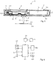
- the Figure 3 and Figure 4 show the sensor device 1 in various isometric representations with further details.
- the sensor device 1 can be fastened to the window frame or a door frame by means of screws through the screw holes 13. Alternatively, it can also be attached using double-sided adhesive tape 30.
- the upper housing part 3 has a recess 31 which receives the optically transparent area 8 when it is placed on the lower housing part 2.
- latching hooks 90 arranged on the lower housing part 2, which, in conjunction with latching recesses 32 arranged in the interior of the upper housing part 3, form a latching connection between the lower housing part 2 and the upper housing part 3, so that the upper housing part 3 is securely fastened to the lower housing part 2, for one Changing the battery but can be easily removed again.
- the Figure 5 shows the sensor device 1 with the lower housing part 2 with the upper housing part 3 removed, the in Figure 5 is not shown. A section of the window sash 20 can also be seen.
- the sensor device 1 emits light 51 via the reflection light barrier through the optically transparent area 8 onto the window sash 20.
- Light 52 reflected by the window sash 20 strikes the light sensor of the reflection light barrier through the optically transparent area 8.
- the window sash 20 is open, no light can be reflected from the latter to the light sensor.
- a reflector element 53 can be attached to the window sash 20 or to a door.
- the reflector element 53 can be designed, for example, in the form of a piece of adhesive tape or another sticker.
- the Figure 6 shows the internal structure of the sensor device 1 in a schematic representation.
- a microprocessor 60 is provided as the central component.
- the control element 11 and the sabotage contact 9 are connected to this.
- a reflected light barrier 61 is provided as the sensor element of the sensor device 1.
- This has a light source, for example in the form of a light-emitting diode, and a light sensor, for example in the form of a photo transistor, a photo diode or a photo resistor.
- the microprocessor 60 is coupled to a radio data transmission unit 62, for example in the form of the radio module TRX868-TFK-SL.
- the microprocessor 60 is also coupled to output means 63, for example in the form of two light-emitting diodes or a duo-color LED. These are structurally arranged in the housing of the sensor device in such a way that their emitted light can be perceived from the outside through the opening 12.
- the microprocessor 60 and the further components to be supplied with electrical energy are connected to the electrical energy source 4.
- the electrical energy source 4 can be followed by a step-up converter 64, by means of which a low nominal voltage of the electrical energy source 4 is converted into a higher operating voltage of the microprocessor 60 and further components.
- a voltage of 1.5 V provided by the electrical energy source can be converted into a voltage of 3 V by means of step-up converter 64.
- the electronics unit of the sensor device 1 can, for example, by two separate Electrical modules (boards) 54, 55 may be formed, which are arranged side by side in the lower housing part 2.
- the radio data transmission unit can be arranged on the module 55.
- the module 55 is connected to an antenna 50 laid in the antenna receiving channel 10.
- the microprocessor and further components can be arranged on the assembly 54.
- the microprocessor 60 can emit a sabotage signal via the radio data transmission unit 62.
- a learning function of the sensor device 1 can be activated by means of the control element 11. Accordingly, the control element 11 is also to be regarded as a configuration button, with the aid of which the sensor device e.g. can be taught to a specific building monitoring system or an actuator.
Description
Die Erfindung betrifft eine als Tür- oder Fenstersensor einer Gebäudeüberwachungsanlage bzw. als Komponente eines Hausautomationssystems ausgebildete Sensoreinrichtung gemäß dem Anspruch 1.The invention relates to a sensor device designed as a door or window sensor of a building monitoring system or as a component of a home automation system.
Allgemein betrifft die Erfindung das Gebiet der Gebäudeüberwachung durch eine Überwachungsanlage, z.B. in Form einer Alarmanlage. Zur Überwachung, ob eine Tür oder ein Fenster geöffnet ist, werden üblicherweise sogenannte Tür- oder Fensterkontakte verwendet, die durch mechanische Sensierung mittels eines Schaltkontakts oder durch magnetisch betätigte Reed-Kontakte eine geöffnete Tür oder ein geöffnetes Fenster erkennen können. Insbesondere magnetisch arbeitende Tür- oder Fensterkontakte sind weit verbreitet, haben aber den Nachteil, dass immer zwei Bauteile zu montieren sind, nämlich der Tür- oder Fensterkontakt und ein damit zusammenwirkender Magnet. Dies ist mit einem gewissen Montageaufwand verbunden. Zusätzlich muss der Magnet genau ausgerichtet werden. Es kann außerdem passieren, dass der Magnet bei Reinigungsarbeiten entfernt, beschädigt oder nach einem Ablösen falsch wieder angebracht wird. Zudem sind die häufig verwendeten Neodym-Magnete teuer und aus ökologischer Sicht bedenklich, da sie zu den seltenen Erden zählen.In general, the invention relates to the field of building surveillance by a surveillance system, e.g. in the form of an alarm system. To monitor whether a door or a window is open, so-called door or window contacts are usually used, which can detect an open door or an open window by mechanical sensing by means of a switch contact or by magnetically operated reed contacts. Magnetically operating door or window contacts in particular are widespread, but have the disadvantage that two components always have to be installed, namely the door or window contact and a magnet interacting with it. This involves a certain amount of assembly work. In addition, the magnet must be precisely aligned. It can also happen that the magnet is removed during cleaning, damaged or incorrectly replaced after it has been removed. In addition, the frequently used neodymium magnets are expensive and, from an ecological point of view, questionable because they are rare earths.
Aus der
Aus einer Bedienungsanleitung der Firma eQ-3 (XP055663516) ist ein Vormodell der Sensorvorrichtung bekannt.A pre-model of the sensor device is known from an operating manual from the company eQ-3 (XP055663516).
Der Erfindung liegt daher die Aufgabe zugrunde, einen verbesserten Tür-/Fensterkontakt oder allgemein gesagt eine entsprechende Sensoreinrichtung anzugeben, die nicht mit solchen Nachteilen behaftet ist.The invention is therefore based on the object of specifying an improved door / window contact or, generally speaking, a corresponding sensor device which does not have such disadvantages.
Diese Aufgabe wird durch eine als Tür- oder Fenstersensor einer Gebäudeüberwachungsanlage ausgebildete Sensoreinrichtung gemäß Anspruch 1 gelöst.This object is achieved by a sensor device designed as a door or window sensor of a building monitoring system according to claim 1.
Das Warnsignal zeigt dementsprechend an, dass die von der Sensoreinrichtung überwachte Tür oder das Fenster geöffnet ist oder geöffnet wird. Die Gebäudeüberwachungsanlage kann das Warnsignal dann z.B. zur Auslösung eines Alarms, zur Speicherung im Rahmen einer Datenlogger-Funktion und/oder zur Weiterleitung an die Polizei oder an einen Sicherheitsdienst nutzen.The warning signal accordingly indicates that the door or window monitored by the sensor device is open or is being opened. The building monitoring system can then e.g. use for triggering an alarm, for storage as part of a data logger function and / or for forwarding to the police or to a security service.
Die Erfindung hat den Vorteil, dass nur noch ein Bauteil zu montieren ist, nämlich die erfindungsgemäße Sensoreinrichtung. Zusätzliche Teile, wie bisher der Magnet, entfallen und müssen demzufolge nicht montiert werden. Zudem werden die Funktion sowie die Überwachungssicherheit der Gebäudeüberwachung mit der erfindungsgemäßen Sensoreinrichtung verbessert, weil statt des bisherigen magnetischen Überwachungsprinzips nun durch den Einsatz einer Reflexlichtschranke, auch Reflexkoppler genannt, ein optisches Überwachungsprinzip vorgeschlagen wird. Das neuartige Überwachungsprinzip der erfindungsgemäßen Sensoreinrichtung ist weniger anfällig gegenüber Einbau-Toleranzen und insbesondere weniger anfällig gegenüber nachträglichen Einflüssen z.B. durch Reinigungsarbeiten, da es nicht vorkommen kann, dass der sonst erforderliche zusätzliche Magnet verloren geht, denn er ist hier gar nicht erforderlich.The invention has the advantage that only one component has to be assembled, namely the sensor device according to the invention. Additional parts, such as the magnet, are no longer required and therefore do not have to be installed. In addition, the function and the monitoring security of the building monitoring system are improved with the sensor device according to the invention, because instead of the previous magnetic monitoring principle, an optical monitoring principle is now proposed through the use of a reflex light barrier, also called reflex coupler. The novel monitoring principle of the sensor device according to the invention is less susceptible to installation tolerances and in particular less susceptible to subsequent influences, for example due to cleaning work, since it cannot happen that the additional magnet which would otherwise be necessary is lost, since it is not necessary here.
Eine Reflexlichtschranke weist typischerweise wenigstens eine Lichtquelle, z.B. in Form einer LED, und wenigstens einen Lichtsensor auf, z.B. in Form eines Fototransistors, einer Fotodiode oder eines Fotowiderstands.A reflex light barrier typically has at least one light source, e.g. in the form of an LED, and at least one light sensor, e.g. in the form of a photo transistor, a photo diode or a photo resistor.
Gemäß einer vorteilhaften Weiterbildung der Erfindung ist vorgesehen, dass die Sensoreinrichtung eine in dem Gehäuse integrierte Datenübertragungseinheit aufweist, wobei die Sensoreinrichtung zur drahtlosen Übertragung des Warnsignals, wenn eine von der Sensoreinrichtung mittels eines Sensorelements überwachte Tür oder ein Fenster geöffnet ist oder geöffnet wird, mittels der Datenübertragungseinheit an eine von der Sensoreinrichtung entfernt angeordnete Gebäudeüberwachungsanlage eingerichtet ist. Dies hat den Vorteil, dass die Montage der Sensoreinrichtung weiter vereinfacht wird, da keine Kabel zwischen der Sensoreinrichtung und der entfernt angeordneten Gebäudeüberwachungsanlage verlegt werden müssen. Die Datenübertragungseinheit kann z.B. als optische Datenübertragungseinheit ausgebildet sein, z.B. zur Übertragung des Warnsignals oder anderer Daten über Lichtsignale mit sichtbarem oder unsichtbarem Licht, z.B. mittels Infrarotlicht.According to an advantageous development of the invention, it is provided that the sensor device has a data transmission unit integrated in the housing, the sensor device for wireless transmission of the warning signal when a door or a window monitored by the sensor device is opened or opened by means of the sensor element Data transmission unit to a building surveillance system arranged away from the sensor device. This has the advantage that the assembly of the sensor device is further simplified since no cables have to be laid between the sensor device and the remote building monitoring system. The data transmission unit can e.g. be designed as an optical data transmission unit, e.g. to transmit the warning signal or other data via light signals with visible or invisible light, e.g. using infrared light.
Gemäß einer vorteilhaften Weiterbildung der Erfindung ist vorgesehen, dass die Datenübertragungseinheit als Funk-Datenübertragungseinheit ausgebildet ist. Dies hat den Vorteil, dass auch größere Entfernungen oder Strecken zur Gebäudeüberwachungsanlage, bei denen kein optischer Kontakt zwischen der Sensoreinrichtung und der Gebäudeüberwachungsanlage besteht, bei der Datenübertragung überwunden werden können. Zudem können bereits normierte Funkprotokolle und Funkfrequenzen eingesetzt werden, wie z.B. 868,3 MHz mit einem Empfänger der Kategorie SRD Category 2.According to an advantageous development of the invention, it is provided that the data transmission unit is designed as a radio data transmission unit. This has the advantage that even greater distances or distances to the building monitoring system, for which there is no optical contact between the sensor device and the building monitoring system, can be covered during data transmission. In addition, standardized radio protocols and radio frequencies can be used, e.g. 868.3 MHz with a SRD
Gemäß einer vorteilhaften Weiterbildung der Erfindung ist vorgesehen, dass die Sensoreinrichtung zur Datenübertragung über die Funk-Datenübertragungseinheit mit einem auf einen Maximalwert begrenzten Duty cycle eingerichtet ist, insbesondere einem Duty cycle bis zu 1 %. Dies hat den Vorteil, dass der vorhandene Funkkanal gut ausgenutzt werden kann und eine Vielzahl von Sensoreinrichtungen und ggf. weitere den Funkkanal nutzende Einrichtungen gleichzeitig betrieben werden können. Als Duty cycle wird dabei die maximale Sendezeit einer Sensoreinrichtung in einem vorbestimmten Zeitraum, z.B. in einer Stunde, verstanden. Bei einem auf einen Wert von 1 % begrenzten Duty cycle darf eine Sensoreinrichtung somit in dem vorbestimmten Zeitraum nur über insgesamt 1 % dieses Zeitraums senden, somit für 36 Sekunden bei einem Zeitraum von einer Stunde. Bei Erreichen des Maximalwerts darf eine Sensoreinrichtung nicht mehr senden, bis der vorbestimmte Zeitraum abgelaufen ist und ein neuer Zeitraum beginnt.According to an advantageous development of the invention, it is provided that the sensor device for data transmission via the radio data transmission unit is set up with a duty cycle limited to a maximum value, in particular a duty cycle of up to 1%. This has the Advantage that the existing radio channel can be used well and a large number of sensor devices and possibly other devices using the radio channel can be operated simultaneously. The duty cycle is understood to mean the maximum transmission time of a sensor device in a predetermined time period, for example in one hour. In the case of a duty cycle limited to a value of 1%, a sensor device may therefore only transmit in the predetermined time period over a total of 1% of this time period, thus for 36 seconds over a period of one hour. When the maximum value is reached, a sensor device may no longer transmit until the predetermined period has expired and a new period begins.
Gemäß einer vorteilhaften Weiterbildung der Erfindung ist vorgesehen, dass die Funk-Datenübertragungseinheit eine Antenne aufweist, die in dem Gehäuse, insbesondere mehrfach abgewinkelt, verlegt ist. Dies hat den Vorteil, dass die Antenne optisch verdeckt ist und nicht störend wirkt. In dem Gehäuse kann insbesondere ein Antennenaufnahmekanal vorgesehen sein, in dem die Antenne zu verlegen ist. Dies hat den Vorteil, dass die Antenne immer an einer definierten Stelle verlegt ist und diese Position auch nicht verlassen kann.According to an advantageous development of the invention, it is provided that the radio data transmission unit has an antenna which is laid in the housing, in particular angled several times. This has the advantage that the antenna is optically covered and does not interfere. In particular, an antenna receiving channel can be provided in the housing, in which the antenna is to be laid. This has the advantage that the antenna is always installed at a defined point and cannot leave this position.
Gemäß einer vorteilhaften Weiterbildung der Erfindung ist vorgesehen, dass die Reflexlichtschranke als Infrarot-Reflexlichtschranke ausgebildet ist. Dies hat den Vorteil, dass das von der Sensoreinrichtung abgestrahlte Licht von Personen nicht wahrgenommen wird. Zudem kann hierdurch die Störsicherheit der Sensoreinrichtung im Vergleich zum sichtbaren Licht verbessert werden.According to an advantageous development of the invention, it is provided that the reflected light barrier is designed as an infrared reflected light barrier. This has the advantage that the light emitted by the sensor device is not perceived by people. This also improves the immunity to interference of the sensor device compared to visible light.
Gemäß einer vorteilhaften Weiterbildung der Erfindung ist vorgesehen, dass die Sensoreinrichtung als mikroprozessorgesteuerte Sensoreinrichtung ausgebildet ist, die wenigstens einen Mikroprozessor aufweist und über den Mikroprozessor hinsichtlich ihrer Funktionalität konfigurierbar ist. Dies hat den Vorteil, dass die Sensoreinrichtung sehr flexibel eingesetzt werden kann und durch ihre Konfigurierbarkeit an verschiedene Einsatzfälle angepasst werden kann.According to an advantageous development of the invention, it is provided that the sensor device is designed as a microprocessor-controlled sensor device which has at least one microprocessor and its functionality can be configured via the microprocessor. This has the advantage that the sensor device can be used very flexibly and, due to its configurability, can be adapted to different applications.
Als Mikroprozessor sei in diesem Fall jedes Elektronikbauteil verstanden, das einen Mikroprozessor aufweist, als solcher ausgebildet ist oder eine solche Funktion hat, insbesondere Mikrocontroller, Mikrocomputer, FPGAs, ASICs.In this case, a microprocessor is understood to mean any electronic component which has a microprocessor, is designed as such or has such a function, in particular microcontrollers, microcomputers, FPGAs, ASICs.
Gemäß einer vorteilhaften Weiterbildung der Erfindung ist vorgesehen, dass die Sensoreinrichtung wenigstens ein von einem Benutzer betätigbares Bedienelement aufweist. Dies hat den Vorteil, dass vom Benutzer auf einfache Weise Einstellungen an der Sensoreinrichtung vorgenommen werden können. Das Bedienelement kann z.B. als Taster oder als berührungsloser Kontakt, z.B. als magnetisch betätigbarer Kontakt, ausgebildet sein.According to an advantageous development of the invention, it is provided that the sensor device has at least one control element that can be actuated by a user. This has the advantage that the user can easily make settings on the sensor device. The control element can e.g. as a button or as a contactless contact, e.g. be designed as a magnetically actuated contact.
Gemäß einer vorteilhaften Weiterbildung der Erfindung ist vorgesehen, dass über das Bedienelement ein Anlernmodus der Sensoreinrichtung aktivierbar ist, in dem die Funktionalität der Sensoreinrichtung konfigurierbar ist. Dies hat den Vorteil, dass auf einfache Weise der Anlernmodus der Sensoreinrichtung aktiviert werden kann, indem ein Benutzer einfach das Bedienelement betätigt. Ein weiterer Vorteil ist, dass durch den Anlernmodus eine sehr benutzerfreundliche Art der Konfiguration der Funktionalität der Sensoreinrichtung realisiert werden kann.According to an advantageous development of the invention, it is provided that a teach-in mode of the sensor device can be activated via the control element, in which the functionality of the sensor device can be configured. This has the advantage that the teach-in mode of the sensor device can be activated in a simple manner by a user simply actuating the control element. Another advantage is that the teach-in mode enables a very user-friendly way of configuring the functionality of the sensor device.
Die Sensoreinrichtung kann auch ein oder mehrere Ausgabeelemente aufweisen, wie z.B. Lichtquellen oder sonstige Ausgabeeinheiten, über die dem Benutzer eine Rückmeldung über den Betriebsstatus der Sensoreinrichtung gegeben werden kann.The sensor device can also have one or more output elements, such as Light sources or other output units via which the user can be given feedback on the operating status of the sensor device.
Gemäß einer vorteilhaften Weiterbildung der Erfindung ist vorgesehen, dass die Sensoreinrichtung wenigstens einen Sabotagekontakt aufweist, durch den detektierbar ist, ob das Gehäuse der Sensoreinrichtung geöffnet bzw. entfernt worden ist. Dies hat den Vorteil, dass auch eine eventuelle Manipulation der Sensoreinrichtung nicht unerkannt bleibt, sondern von der Sensoreinrichtung durch den Sabotagekontakt erkannt werden kann. Wird durch den Sabotagekontakt detektiert, dass das Gehäuse der Sensoreinrichtung geöffnet bzw. entfernt worden ist, kann die Sensoreinrichtung ein Sabotagesignal abgeben, das z.B. wie das Warnsignal an die Gebäudeüberwachungsanlage übertragen wird und dort entsprechend verarbeitet wird, z.B. zum Erzeugen eins Alarms, zum Datenloggen und/oder zur Information der Polizei oder von sonstigen Sicherheitskräften.According to an advantageous development of the invention, it is provided that the sensor device has at least one tamper contact, by means of which it can be detected whether the housing of the sensor device has been opened or removed. This has the advantage that any manipulation of the sensor device does not remain undetected, but can be recognized by the sensor device through the tamper contact. Is through the sabotage contact Detects that the housing of the sensor device has been opened or removed, the sensor device can emit a sabotage signal which, for example, is transmitted to the building monitoring system like the warning signal and processed there accordingly, for example to generate an alarm, for data logging and / or for information the police or other security forces.
Gemäß einer vorteilhaften Weiterbildung der Erfindung ist vorgesehen, dass die Sensoreinrichtung eine Selbstüberwachungseinheit aufweist, die zur Selbstüberwachung der Sensoreinrichtung eingerichtet ist und bei einem erkannten Fehler der Sensoreinrichtung zur Ausgabe eines Fehlercodes eingerichtet ist. Dies hat den Vorteil, dass die Sensoreinrichtung selbst gewisse Mindestüberwachungen durchführen kann, z.B. hinsichtlich ihrer eigenen Komponenten. So kann durch die Sensoreinrichtung z.B. die Funktion der Reflexlichtschranke überwacht werden, z.B. dahingehend, ob die Lichtquelle noch funktionsfähig ist. Es kann auch die Datenübertragungseinheit hinsichtlich der korrekten Funktion überwacht werden. Ferner kann der Status einer elektrischen Energiequelle der Sensoreinrichtung überwacht werden, d. h. es kann z.B. eine Information über eine Unterspannung oder eine schwache Batterie ausgegeben werden. Auch kann als Fehler überwacht werden, ob die Gebäudeüberwachungsanlage wie vorgesehen auf Kommunikationssignale der Sensoreinrichtung reagiert. Ist dies nicht der Fall, kann dies als Fehler mittels eines Fehlercodes ausgegeben werden. Die Fehlercodes können z.B. mittels einer Lichtquelle der Sensoreinrichtung in Form eines Blinkcodes ausgegeben werden.According to an advantageous development of the invention, it is provided that the sensor device has a self-monitoring unit which is set up for self-monitoring of the sensor device and is set up to output an error code when a fault is detected in the sensor device. This has the advantage that the sensor device itself can carry out certain minimum monitoring, e.g. regarding their own components. The sensor device can e.g. the function of the reflex light barrier can be monitored, e.g. as to whether the light source is still functional. The data transmission unit can also be monitored for correct functioning. Furthermore, the status of an electrical energy source of the sensor device can be monitored, i. H. e.g. information about an undervoltage or a weak battery is output. It can also be monitored as an error whether the building monitoring system is reacting as intended to communication signals from the sensor device. If this is not the case, this can be output as an error using an error code. The error codes can e.g. are output by means of a light source of the sensor device in the form of a blink code.
Gemäß einer vorteilhaften Weiterbildung der Erfindung ist vorgesehen, dass die Sensoreinrichtung zur gepulsten Betätigung der Lichtquelle der Reflexlichtschranke eingerichtet ist und zur Überprüfung, ob das über den Lichtsensor der Reflexlichtschranke empfangene Licht zeitlich mit der gepulsten Betätigung der Lichtquelle im Wesentlichen oder vollständig übereinstimmt. Als Betätigung der Lichtquelle wird dabei ein Einschalten der Lichtquelle verstanden. Dies hat den Vorteil, dass durch die gepulste Betätigung elektrische Energie gespart wird, im Vergleich zu einer ständigen Betätigung der Lichtquelle. Dies ist insbesondere bei einer im Gehäuse der Sensoreinrichtung integrierten Energiequelle, z.B. in Form eines Akkumulators oder einer Batterie, von großem Vorteil. Zudem kann hierdurch eine Sicherheitsüberprüfung durchgeführt werden, ob das vom Lichtsensor empfangene Licht zu dem von der Lichtquelle abgegebenen Licht passt, zumindest in zeitlicher Hinsicht. Ist dies nicht der Fall, kann ebenfalls von der Sensoreinrichtung ein Fehler erkannt werden und ausgegeben werden.According to an advantageous development of the invention, it is provided that the sensor device is set up for pulsed actuation of the light source of the reflective light barrier and for checking whether the light received via the light sensor of the reflective light barrier coincides substantially or completely with the pulsed actuation of the light source. Activation of the light source is understood to mean switching on the light source. This has the Advantage that the pulsed actuation saves electrical energy compared to a constant actuation of the light source. This is of great advantage in particular in the case of an energy source integrated in the housing of the sensor device, for example in the form of an accumulator or a battery. In addition, this can be used to carry out a security check as to whether the light received by the light sensor matches the light emitted by the light source, at least in terms of time. If this is not the case, an error can likewise be recognized and output by the sensor device.
Gemäß der Erfindung ist vorgesehen, dass die Sensoreinrichtung zur Modulation des von der Lichtquelle der Reflexlichtschranke abgegebenen Lichts nach einem vorgegebenen Code eingerichtet ist und zur Überprüfung, ob das über den Lichtsensor der Reflexlichtschranke empfangene Licht eine Modulation mit einer Codierung aufweist, die dem vorgegebenen Code entspricht. Dies hat den Vorteil, dass die Sicherheit gegen Manipulationen weiter erhöht werden kann. Es kann z.B. ein Pulscode als vorgegebener Code verwendet werden, insbesondere ein Code mit variierender Verschlüsselung.According to the invention, it is provided that the sensor device is configured to modulate the light emitted by the light source of the reflex light barrier according to a predetermined code and to check whether the light received via the light sensor of the reflex light barrier has a modulation with a coding that corresponds to the predetermined code . This has the advantage that the security against manipulation can be further increased. For example, a pulse code can be used as a predetermined code, in particular a code with varying encryption.
Gemäß der Erfindung ist vorgesehen, dass die Sensoreinrichtung dazu eingerichtet ist das Warnsignal abzugeben, wenn bei im Wesentlichen oder vollständig unbetätigter Lichtquelle der Reflexlichtschranke das über den Lichtsensor der Reflexlichtschranke empfangene Licht einen bestimmten Schwellenwert überschreitet. Dies hat den Vorteil, dass eine zusätzliche Erkennung eines geöffneten Fensters oder einer geöffneten Tür möglich ist. Hierbei ist die Lichtquelle der Reflexlichtschranke nicht eingeschaltet. Dennoch wird in diesen Phasen das über den Lichtsensor empfangene Licht ausgewertet, d. h. die vom Lichtsensor abgegebenen Signale. Zeigen diese Signale an, dass vom Lichtsensor relativ viel Licht empfangen wird, sodass ein bestimmter Schwellenwert überschritten ist, so kann davon ausgegangen werden, dass ein überwachtes Fenster geöffnet ist, in das Sonnenlicht herein scheint, oder dass eine andere Fremdlichtquelle und auf den Lichtsensor trifft.According to the invention it is provided that the sensor device is set up to emit the warning signal when the light received by the light sensor of the reflex light barrier exceeds a certain threshold value when the light sensor of the reflex light barrier is essentially or completely inactive. This has the advantage that an additional detection of an open window or an open door is possible. The light source of the reflex light barrier is not switched on. Nevertheless, the light received by the light sensor is evaluated in these phases, ie the signals emitted by the light sensor. If these signals indicate that a relatively large amount of light is being received by the light sensor, so that a certain threshold value has been exceeded, it can be assumed that a monitored window is open into the sunlight seems, or that another external light source hits the light sensor.
Gemäß einer vorteilhaften Weiterbildung der Erfindung weist die Sensoreinrichtung eine elektrische Energiequelle zur elektrischen Energieversorgung der elektronischen Bauteile der Sensoreinrichtung auf. Auf diese Weise ist die Sensoreinrichtung auch hinsichtlich der Energieversorgung autark und benötigt keine äußeren elektrischen Zuleitungen für die Energieversorgung. Hierdurch wird die Montage der Sensoreinrichtung weiter vereinfacht. Die elektrische Energiequelle kann z.B. als Batterie oder Akkumulator ausgebildet sein, oder als Solarzelle oder als Kombination davon. Akkumulatoren sind bekanntlich wieder aufladbar, Batterien nicht.According to an advantageous development of the invention, the sensor device has an electrical energy source for the electrical energy supply of the electronic components of the sensor device. In this way, the sensor device is also self-sufficient with regard to the energy supply and does not require any external electrical supply lines for the energy supply. This further simplifies the assembly of the sensor device. The electrical energy source can e.g. be designed as a battery or accumulator, or as a solar cell or a combination thereof. Accumulators are known to be rechargeable, batteries are not.
Gemäß einer vorteilhaften Weiterbildung der Erfindung ist vorgesehen, dass die Sensoreinrichtung zum Betrieb mit einer einzelligen Batterie als elektrische Energiequelle eingerichtet ist. Dies hat den Vorteil, dass ein Batteriewechsel vereinfacht ist, weil nur eine einzige Batteriezelle zu tauschen ist. Zudem ist der Platzbedarf für die elektrische Energiequelle hierdurch relativ gering, weil z.B. eine schlanke Batterie eingesetzt werden kann, z.B. in Form einer AA- oder AAA-Zelle.According to an advantageous development of the invention, it is provided that the sensor device is set up to operate with a single-cell battery as an electrical energy source. This has the advantage that a battery change is simplified because only a single battery cell has to be replaced. In addition, the space required for the electrical energy source is relatively small, because e.g. a slim battery can be used, e.g. in the form of an AA or AAA cell.
Gemäß einer vorteilhaften Weiterbildung der Erfindung ist vorgesehen, dass die Sensoreinrichtung eine im Gehäuse integrierte elektrische Energiequelle mit nachgeschaltetem Step-up-Wandler zur elektrischen Energieversorgung der elektronischen Bauteile der Sensoreinrichtung aufweist. Dies hat den Vorteil, dass auch mit einer elektrischen Energiequelle, die eine relativ geringe Nennspannung aufweist, wie z.B. eine einzige Batteriezelle oder einzige Solarzelle, handelsübliche elektronische Bauteile mit höherer Nennspannung betrieben werden können. Um lange Betriebszeiten der Sensoreinrichtung bei Verwendung einer Batteriezelle zu realisieren, ist es vorteilhaft, den Step-up-Wandler, auch Aufwärtswandler genannt, mit einem Mikroprozessor der Sensoreinrichtung zu kombinieren, der selbst einen geringen Strombedarf hat, wie z.B. einen 32-bit-Mikrocontroller mit Cortex-M-Technologie der Firma Energy-Micro.According to an advantageous development of the invention, it is provided that the sensor device has an electrical energy source integrated in the housing with a downstream step-up converter for the electrical energy supply of the electronic components of the sensor device. This has the advantage that even with an electrical energy source that has a relatively low nominal voltage, such as a single battery cell or single solar cell, commercially available electronic components with a higher nominal voltage can be operated. In order to achieve long operating times of the sensor device when using a battery cell, it is advantageous to combine the step-up converter, also called step-up converter, with a microprocessor of the sensor device, which itself has a low power requirement, such as eg a 32-bit microcontroller with Cortex-M technology from Energy-Micro.
Gemäß einer vorteilhaften Weiterbildung der Erfindung ist vorgesehen, dass der Step-up-Wandler derart bezüglich der Funk-Datenübertragungseinheit und/oder deren Antenne in dem Gehäuse angeordnet ist, dass Einstreuungen des Step-up-Wandlers in den Fußpunkt der Antenne minimiert sind. Dies hat den Vorteil, dass unerwünschte gegenseitige Beeinflussungen zwischen dem Step-up-Wandler und der Funk-Datenübertragungseinheit vermieden werden und eine ungestörte Funk-Kommunikation zwischen der Sensoreinrichtung und der Gebäudeüberwachungsanlage möglich ist.According to an advantageous development of the invention, it is provided that the step-up converter is arranged in the housing with respect to the radio data transmission unit and / or its antenna in such a way that interference from the step-up converter in the base point of the antenna is minimized. This has the advantage that undesirable mutual influences between the step-up converter and the radio data transmission unit are avoided and undisturbed radio communication between the sensor device and the building monitoring system is possible.
Gemäß einer vorteilhaften Weiterbildung der Erfindung ist vorgesehen, dass das Gehäuse wenigstens zweiteilig mit einem Gehäuseunterteil, das eine Elektronikeinheit der Sensoreinrichtung aufnimmt, und einem in Form einer Abdecckappe ausgebildeten Gehäuseoberteil ausgebildet ist, das auf das Gehäuseunterteil aufsetzbar ist, wobei das Gehäuse wenigstens einen optisch durchlässigen Bereich für die Ausstrahlung des Lichts der Lichtquelle der Reflexlichtschranke und dem Empfang von dessen Reflexionen aufweist. Dies hat den Vorteil, dass das Gehäuse auch vom Anwender einfach montiert und demontiert werden kann, z.B. um einen Batteriewechsel vorzunehmen. Zudem kann die Überwachung des Fensters oder der Tür durch die Sensoreinrichtung ohne Weiteres durch das geschlossene Gehäuse erfolgen, indem dort der optisch durchlässige Bereich vorgesehen ist, z.B. in Form eines transparenten Bereichs. Ein solches geschlossenes Gehäuse hat den Vorteil, dass die darin angeordneten Bauelemente gut vor Umgebungseinflüssen geschützt sind.According to an advantageous development of the invention, it is provided that the housing is formed at least in two parts with a lower housing part which receives an electronics unit of the sensor device and an upper housing part which is designed in the form of a cover cap and which can be placed on the lower housing part, the housing at least one optically transparent Area for emitting the light of the light source of the reflex light barrier and receiving its reflections. This has the advantage that the housing can also be easily assembled and disassembled by the user, e.g. to change the battery. In addition, the window or door can be easily monitored by the sensor device through the closed housing by providing the optically transparent area there, e.g. in the form of a transparent area. Such a closed housing has the advantage that the components arranged therein are well protected against environmental influences.
Gemäß einer vorteilhaften Weiterbildung der Erfindung ist vorgesehen, dass die Sensoreinrichtung mehrere in Form von Abdeckkappen ausgebildete Gehäuseoberteile aufweist, von denen jeweils ein Gehäuseoberteil nach Wahl des Benutzers mit dem Gehäuseunterteil zu verbinden ist. Dies hat den Vorteil, dass mehrere Abdeckkappen für unterschiedliche Anwendungen bereitgestellt werden können, z.B. Abdeckkappen in unterschiedlichen Farben, um das äußere Erscheinungsbild der Sensoreinrichtung dem Interieur eines Raums oder der Farbe einer Tür oder eines Fensters anzupassen, an der die Sensoreinrichtung montiert werden soll.According to an advantageous development of the invention, it is provided that the sensor device has a plurality of upper housing parts in the form of cover caps, of which one upper housing part is to be connected to the lower housing part at the user's choice. This has the advantage that several cover caps can be provided for different applications, for example cover caps in different colors, in order to adapt the external appearance of the sensor device to the interior of a room or the color of a door or a window on which the sensor device is to be mounted.
Gemäß einer vorteilhaften Weiterbildung der Erfindung ist vorgesehen, dass das Gehäuse als weiteres Gehäusebauteil eine innere Abdeckkappe aufweist, die zumindest die Elektronikeinheit in dem Gehäuse abdeckt, wobei die innere Abdeckkappe bei aufgesetztem Gehäuseoberteil von diesem im Wesentlichen oder vollständig überdeckt ist. Dies hat den Vorteil, dass die Elektronikeinheit auch bei abgenommenem Gehäuseoberteil, z.B. für einen Batteriewechsel, weiter vor Umgebungseinflüssen geschützt ist. Ein weiterer Vorteil ist, dass die innere Abdeckkappe zugleich zur Führung und Halterung der Antenne der Funk-Datenübertragungseinheit verwendet werden kann, indem darin ein entsprechender Antennenaufnahmekanal zum Verlegen der Antenne vorgesehen ist.According to an advantageous development of the invention, it is provided that the housing, as a further housing component, has an inner cover cap, which at least covers the electronics unit in the housing, the inner cover cap being substantially or completely covered by this when the upper housing part is attached. This has the advantage that the electronics unit can be removed even when the upper housing part is removed, e.g. for a battery change, is further protected from environmental influences. A further advantage is that the inner cover cap can also be used for guiding and holding the antenna of the radio data transmission unit by providing a corresponding antenna receiving channel for laying the antenna.
Gemäß einer vorteilhaften Weiterbildung der Erfindung ist vorgesehen, dass die innere Abdeckkappe optisch durchlässig ist, z.B. transparent. Dies hat den Vorteil, dass die Reflexlichtschranke noch durch die innere Abdeckkappe hindurch ihre optische Überwachungsfunktion ausüben kann.According to an advantageous development of the invention, it is provided that the inner cover cap is optically transparent, e.g. transparent. This has the advantage that the reflex light barrier can still perform its optical monitoring function through the inner cover cap.
Gemäß einer vorteilhaften Weiterbildung der Erfindung ist vorgesehen, dass das Gehäuse ein Batteriefach aufweist, in das eine auswechselbare Batterie als elektrische Energiequelle der Sensoreinrichtung einsetzbar ist. Dies hat den Vorteil, dass die Batterie vom Anwender leicht gewechselt werden kann.According to an advantageous development of the invention, it is provided that the housing has a battery compartment into which a replaceable battery can be used as the electrical energy source of the sensor device. This has the advantage that the battery can be easily replaced by the user.
Gemäß einer vorteilhaften Weiterbildung der Erfindung ist vorgesehen, dass das Gehäuse eine im Wesentlichen oder vollständig quaderförmige Außenkontur aufweist. Dies hat den Vorteil, dass sich die Sensoreinrichtung optisch gut an übliche Tür- und Fensterflügel anpasst und relativ unauffällig ist.According to an advantageous development of the invention, it is provided that the housing has an essentially or completely cuboid outer contour. This has the advantage that the sensor device is optically good adapts to normal door and window sashes and is relatively inconspicuous.
Gemäß einer vorteilhaften Weiterbildung der Erfindung ist vorgesehen, dass die größte Außenabmessung (z.B. die Länge) des Gehäuses wenigstens fünfmal so groß ist wie kleinste Außenabmessung (z.B. die Breite oder Höhe) des Gehäuses. Dies hat den Vorteil, dass das Gehäuse in einer länglichen schlanken Form bereitgestellt werden kann, so dass die Sensoreinrichtung ein insgesamt relativ unauffälliges, in jedem Fall aber optisch ansprechendes Erscheinungsbild bietet.According to an advantageous development of the invention, it is provided that the largest external dimension (e.g. the length) of the housing is at least five times as large as the smallest external dimension (e.g. the width or height) of the housing. This has the advantage that the housing can be provided in an elongated, slim shape, so that the sensor device offers an overall relatively unobtrusive, but in any case visually appealing, appearance.
Gemäß einer vorteilhaften Weiterbildung der Erfindung ist vorgesehen, dass die größte Außenabmessung des Gehäuses wenigstens fünfmal so groß ist wie zweitkleinste Außenabmessung des Gehäuses. Dies hat den Vorteil, dass das Gehäuse in einer länglichen schlanken Form bereitgestellt werden kann, so dass die Sensoreinrichtung ein insgesamt relativ unauffälliges, in jedem Fall aber optisch ansprechendes Erscheinungsbild bietet.According to an advantageous development of the invention, it is provided that the largest outer dimension of the housing is at least five times as large as the second smallest outer dimension of the housing. This has the advantage that the housing can be provided in an elongated, slim shape, so that the sensor device offers an overall relatively unobtrusive, but in any case visually appealing, appearance.
Gemäß einer vorteilhaften Weiterbildung der Erfindung ist vorgesehen, dass eine elektrische Energiequelle der Sensoreinrichtung in dem Gehäuse in Richtung der größten Außenabmessung des Gehäuses hinter den elektronischen Bauteilen der Sensoreinrichtung angeordnet ist. Dies hat den Vorteil, dass auch durch den inneren Aufbau der Sensoreinrichtung eine Gehäuseformgebung in einer länglichen schlanken Form gefördert wird, was, wie erwähnt, den Vorteil einer unauffälligen Anbringung und eines ansprechenden optischen Erscheinungsbilds bietet.According to an advantageous development of the invention, it is provided that an electrical energy source of the sensor device is arranged in the housing in the direction of the largest external dimension of the housing behind the electronic components of the sensor device. This has the advantage that the internal structure of the sensor device also promotes a housing shape in an elongated, slim form, which, as mentioned, offers the advantage of an inconspicuous attachment and an appealing visual appearance.
Die Erfindung wird nachfolgend anhand von Ausführungsbeispielen unter Verwendung von Zeichnungen näher erläutert.The invention is explained in more detail below on the basis of exemplary embodiments using drawings.
Es zeigen
- Figur 1
- eine Sensoreinrichtung in Draufsicht bei abgenommenen Gehäuseoberteil und
Figur 2- zwei Anbringungsmöglichkeiten der Sensoreinrichtung an einem Fenster und
- Figur 3-4
- die Sensoreinrichtung in unterschiedlichen isometrischen Ansichten bei abgenommenen Gehäuseoberteil und
Figur 5- eine vergrößerte Draufsicht auf die Sensoreinrichtung bei abgenommenen Gehäuseoberteil und
- Figur 6
- den grundsätzlichen Aufbau der Elektronikeinheit der Sensoreinrichtung in Blockschaltbild-Darstellung.
- Figure 1
- a sensor device in plan view with removed Housing upper part and
- Figure 2
- two attachment options for the sensor device on a window and
- Figure 3-4
- the sensor device in different isometric views with the upper housing part removed and
- Figure 5
- an enlarged plan view of the sensor device with the upper housing part removed and
- Figure 6
- the basic structure of the electronics unit of the sensor device in block diagram representation.
In den Figuren werden gleiche Bezugszeichen für einander entsprechende Elemente verwendet.In the figures, the same reference numerals are used for corresponding elements.
Die
Das Gehäuseoberteil 3 ist als ein im Wesentlichen geschlossenes, nur an der Unterseite offenes Bauteil ausgebildet. An der in
Die Sensoreinrichtung 1 weist einen Antennenaufnahmekanal 10 für eine Antenne der Sensoreinrichtung 1 auf, wobei der Antennenaufnahmekanal 10 insbesondere als nutenförmige Vertiefung in der inneren Abdeckkappe 7 ausgebildet sein kann.The sensor device 1 has an
Zur Befestigung der Sensoreinrichtung 1 an einem Fenster- oder Türrahmen mittels Schrauben sind im Bereich 5 unterhalb der Energiequelle 4 Schraublöcher 13 in dem Gehäuseunterteil 2 vorgesehen.To fasten the sensor device 1 to a window or door frame by means of screws, 4 screw holes 13 are provided in the
Die
Die
Das Gehäuseoberteil 3 weist eine Aussparung 31 auf, die beim Aufsetzen auf das Gehäuseunterteil 2 den optisch durchlässigen Bereich 8 aufnimmt.The
Erkennbar sind ferner mehrere am Gehäuseunterteil 2 angeordnete Rasthaken 90, die in Verbindung mit im Inneren des Gehäuseoberteils 3 angeordneten Rastausnehmungen 32 eine Rastverbindung zwischen dem Gehäuseunterteil 2 und dem Gehäuseoberteil 3 bilden, so dass das Gehäuseoberteil 3 sicher an dem Gehäuseunterteil 2 befestigt ist, für einen Wechsel der Batterie aber leicht wieder davon entfernt werden kann.Also recognizable are a plurality of latching hooks 90 arranged on the
Die
Die
Zur elektrischen Energieversorgung sind der Mikroprozessor 60 und die weiteren mit elektrischer Energie zu versorgenden Bauteile mit der elektrischen Energiequelle 4 verbunden. Der elektrischen Energiequelle 4 kann ein Step-up-Wandler 64 nachgeschaltet sein, durch den eine niedrige Nennspannung der elektrischen Energiequelle 4 in eine höhere Betriebsspannung des Mikroprozessors 60 und weiterer Bauelemente gewandelt wird. So kann z.B. mittels Step-up-Wandlers 64 eine von der elektrischen Energiequelle bereitgestellte Spannung von 1,5 V in eine Spannung von 3 V gewandelt werden.For the electrical energy supply, the
Die Elektronikeinheit der Sensoreinrichtung 1 kann z.B. durch zwei separate elektrische Baugruppen (Platinen) 54, 55 gebildet sein, die nebeneinander in dem Gehäuseunterteil 2 angeordnet sind. So kann auf der Baugruppe 55 z.B. die Funk-Datenübertragungseinheit angeordnet sein. Dementsprechend ist die Baugruppe 55 mit einer in dem Antennenaufnahmekanal 10 verlegten Antenne 50 verbunden. Auf der Baugruppe 54 können z.B. der Mikroprozessor sowie weitere Bauteile angeordnet sein.The electronics unit of the sensor device 1 can, for example, by two separate Electrical modules (boards) 54, 55 may be formed, which are arranged side by side in the
Sofern das Gehäuseoberteil 3 abgenommen wird, wird dies durch den Sabotagekontakt 9 erfasst und durch den Mikroprozessor 60 erkannt. Dementsprechend kann der Mikroprozessor 60 über die Funk-Datenübertragungseinheit 62 ein Sabotagesignal aussenden.If the
Mittels des Bedienelements 11 kann eine Anlernfunktion der Sensoreinrichtung 1 aktiviert werden. Dementsprechend ist das Bedienelement 11 auch als Konfigurationstaster anzusehen, mit dessen Hilfe die Sensoreinrichtung z.B. an eine bestimmte Gebäudeüberwachungsanlage oder einen Aktor angelernt werden kann.A learning function of the sensor device 1 can be activated by means of the
Claims (13)
- Sensor device (1) embodied as a door or window sensor of a building monitoring installation and/or as a component of a house automation system, said sensor device being configured to output a warning signal if a window or a door monitored by the sensor device (1) by means of a sensor element is open or opened, wherein the sensor device (1) is embodied as an autonomously functional, compact component with a housing, which should be assembled on the door frame of a door to be monitored or on the window frame of a window to be monitored, wherein the sensor device (1) has at least one reflection-type photoelectric barrier (61) as a sensor element, which is embodied to emit light (51) from one housing side of the sensor device (1), wherein the housing is embodied at least in two-part form with a housing lower part (2), which receives an electronics unit of the sensor device (1), and a housing upper part (3) embodied in the form of a covering cap, the latter being placeable on the housing lower part (2), wherein the housing has at least one optically transmissive region (8) for the emission of the light (51) from the light source of the reflection-type photoelectric barrier (61) and for the reception of the reflections thereof, characterized in that the housing has an inner covering cap (7), which covers at least the electronics unit in the housing, as a further housing component part, wherein the inner covering cap (7) is at least substantially covered or completely covered by the housing upper part (3) when the latter is mounted.
- Sensor device (1) according to the preceding claim, characterized in that the sensor device (1) has a data transmission unit integrated into the housing, wherein the sensor device (1) is configured to transmit the warning signal wirelessly by means of the data transmission unit to a building monitoring installation disposed at a distance from the sensor device (1) if a window or a door monitored by the sensor device (1) by means of a sensor element is open or opened.
- Sensor device (1) according to the preceding claim, characterized in that the data transmission unit is embodied as a radio data transmission unit (62).
- Sensor device (1) according to the preceding claim, characterized in that the sensor device (1) is configured to transmit data via the radio data transmission unit (62) with a duty cycle that has been restricted to a maximum value, in particular a duty cycle of up to 1%.
- Sensor device (1) according to any one of the preceding claims, characterized in that the sensor device (1) is embodied as a microprocessor-controlled sensor device (1), which has at least one microprocessor (60) and which is configurable in respect of its functionality by way of the microprocessor (60).
- Sensor device (1) according to any one of the preceding claims, characterized in that the sensor device (1) has at least one operator control element (11) that can be actuated by a user.
- Sensor device (1) according to the preceding claim, characterized in that a learning mode of the sensor device (1), in which the functionality of the sensor device (1) is configurable, is actuatable by the operator control element (11).
- Sensor device (1) according to any one of the preceding claims, characterized in that the sensor device (1) has a self-monitoring unit, which is configured to self-monitor the sensor device (1) and to output an error code if a fault of the sensor device (1) is identified.
- Sensor device (1) according to any one of the preceding claims, characterized in that the sensor device (1) is configured to actuate the light source of the reflection-type photoelectric barrier (61) in pulsed fashion and to check whether the light (51) received by way of the light sensor of the reflection-type photoelectric barrier (61) substantially or completely corresponds to the pulsed actuation of the light source in terms of time.
- Sensor device (1) according to the preceding claim, characterized in that the sensor device (1) has a plurality of housing upper parts (3) which are embodied in the form of covering caps, one of which housing upper parts (3) should be connected to the housing lower part (2) in each case, as per the user's choice.
- Sensor device (1) according to any one of the preceding claims, characterized in that the largest external dimension of the housing is at least five times larger than the smallest external dimension of the housing.
- Sensor device (1) according to any one of the preceding claims, characterized in that the largest external dimension of the housing is at least five times larger than the second smallest external dimension of the housing.
- Sensor device (1) according to any one of the preceding claims, characterized in that an electric power source (4) of the sensor device (1) is disposed in the housing behind the electronic components of the sensor device (1) in the direction of the largest external dimension of the housing.
Applications Claiming Priority (1)
| Application Number | Priority Date | Filing Date | Title |
|---|---|---|---|
| DE202014104195.8U DE202014104195U1 (en) | 2014-09-05 | 2014-09-05 | sensor device |
Publications (2)
| Publication Number | Publication Date |
|---|---|
| EP2993650A1 EP2993650A1 (en) | 2016-03-09 |
| EP2993650B1 true EP2993650B1 (en) | 2020-07-29 |
Family
ID=51629372
Family Applications (1)
| Application Number | Title | Priority Date | Filing Date |
|---|---|---|---|
| EP15183478.5A Active EP2993650B1 (en) | 2014-09-05 | 2015-09-02 | Sensor device |
Country Status (3)
| Country | Link |
|---|---|
| EP (1) | EP2993650B1 (en) |
| DE (1) | DE202014104195U1 (en) |
| ES (1) | ES2816775T3 (en) |
Families Citing this family (4)
| Publication number | Priority date | Publication date | Assignee | Title |
|---|---|---|---|---|
| DE202014104195U1 (en) | 2014-09-05 | 2014-09-17 | Elv Elektronik Ag | sensor device |
| DE102016212821B4 (en) * | 2016-07-13 | 2019-03-07 | Martin Weinläder | Device for receiving data |
| DE202017003794U1 (en) | 2017-07-18 | 2017-08-18 | D:R:O:W: Berlin Verwaltungs UG | System for detecting closing and opening conditions of openings of a room |
| CN113433559B (en) * | 2021-06-23 | 2022-09-27 | 西南交通大学 | Infrared measuring device of transformer fire safety margin |
Citations (26)
| Publication number | Priority date | Publication date | Assignee | Title |
|---|---|---|---|---|
| US4250498A (en) | 1978-05-19 | 1981-02-10 | Erwin Sick Gmbh, Optik-Elektronik | Light barrier receiver |
| DE3119876A1 (en) * | 1981-05-19 | 1982-12-16 | Wilhelm Ruf KG, 8000 München | Infrared transmitting/receiving system |
| US4507654A (en) | 1981-10-30 | 1985-03-26 | A. R. F. Products | Security system with infrared optical position detector |
| US4583082A (en) | 1983-06-09 | 1986-04-15 | Igt | Optical door interlock |
| US5055685A (en) | 1989-12-01 | 1991-10-08 | Optex Co., Ltd. | Infrared detecting apparatus |
| DE4011351A1 (en) | 1990-04-07 | 1991-10-24 | Athmer Fa F | MAGNETIC DOOR SEAL |
| EP0503965A1 (en) | 1991-03-15 | 1992-09-16 | Pedro Marrero | Alarm system |
| JP2588667Y2 (en) | 1990-12-06 | 1999-01-13 | 株式会社日本アレフ | Reflective photo sensor |
| US5912619A (en) * | 1997-12-31 | 1999-06-15 | Wells Fargo Alarm Systems, Inc. | Security system using optical sensors |
| WO2001069287A1 (en) | 2000-03-13 | 2001-09-20 | Renato Prescendo | Anti-theft device for buildings |
| US6411215B1 (en) | 1999-02-19 | 2002-06-25 | J. Mitchell Shnier | Optical methods for detecting the position or state of an object |
| EP0929999B1 (en) | 1996-09-27 | 2004-03-03 | Jari Ruuttu | A protective device for shielding an electrical apparatus against environmental conditions |
| US20050201086A1 (en) | 2004-03-11 | 2005-09-15 | Sick Ag | Protective light barrier |
| EP1271439B1 (en) | 2001-06-29 | 2006-07-26 | H.H. Heim & Haus Holding GmbH | Device for monitoring the closure state of doors and windows |
| US7170060B2 (en) | 2004-02-27 | 2007-01-30 | Optex Co., Ltd. | Passive infrared sensor |
| US7196330B2 (en) | 2004-02-27 | 2007-03-27 | Optex Co., Ltd. | Passive infrared sensor |
| EP1918890A1 (en) | 2006-11-01 | 2008-05-07 | EFP Vertriebs- und Servicegesellschaft mbH | Device for displaying the open/closed status of a window or door |
| US7456738B2 (en) | 2005-06-01 | 2008-11-25 | Thermo King Corporation | Transport refrigeration door status sensing device |
| EP2015272A2 (en) | 2007-07-09 | 2009-01-14 | Robert Bosch GmbH | Tamper detector for a security sensor |
| EP2019377A1 (en) | 2007-07-25 | 2009-01-28 | Robert Bosch GmbH | Offset optical security sensor for a door |
| JP2010129005A (en) | 2008-11-30 | 2010-06-10 | Hochiki Corp | Window opening/closing detecting device |
| US7986232B2 (en) | 2006-08-03 | 2011-07-26 | Tyco Safety Products Canada Ltd. | Method and apparatus for using an infrared reflectivity sensor in a security system |
| DE202013001605U1 (en) | 2013-02-19 | 2013-04-05 | Simon Müller | Device for monitoring objects |
| DE202013006363U1 (en) | 2013-07-16 | 2013-08-02 | Marion Peplies E.K. Dekoprofiltechnik | Plisseevorhang |
| US20140240717A1 (en) | 2013-02-27 | 2014-08-28 | Honeywell International Inc. | Apparatus and Method of Using a Light Conduit in a Position Detector |
| DE202014104195U1 (en) | 2014-09-05 | 2014-09-17 | Elv Elektronik Ag | sensor device |
-
2014
- 2014-09-05 DE DE202014104195.8U patent/DE202014104195U1/en active Active
-
2015
- 2015-09-02 EP EP15183478.5A patent/EP2993650B1/en active Active
- 2015-09-02 ES ES15183478T patent/ES2816775T3/en active Active
Patent Citations (27)
| Publication number | Priority date | Publication date | Assignee | Title |
|---|---|---|---|---|
| US4250498A (en) | 1978-05-19 | 1981-02-10 | Erwin Sick Gmbh, Optik-Elektronik | Light barrier receiver |
| DE3119876A1 (en) * | 1981-05-19 | 1982-12-16 | Wilhelm Ruf KG, 8000 München | Infrared transmitting/receiving system |
| US4507654A (en) | 1981-10-30 | 1985-03-26 | A. R. F. Products | Security system with infrared optical position detector |
| US4583082A (en) | 1983-06-09 | 1986-04-15 | Igt | Optical door interlock |
| US5055685A (en) | 1989-12-01 | 1991-10-08 | Optex Co., Ltd. | Infrared detecting apparatus |
| DE4011351A1 (en) | 1990-04-07 | 1991-10-24 | Athmer Fa F | MAGNETIC DOOR SEAL |
| JP2588667Y2 (en) | 1990-12-06 | 1999-01-13 | 株式会社日本アレフ | Reflective photo sensor |
| EP0503965A1 (en) | 1991-03-15 | 1992-09-16 | Pedro Marrero | Alarm system |
| EP0929999B1 (en) | 1996-09-27 | 2004-03-03 | Jari Ruuttu | A protective device for shielding an electrical apparatus against environmental conditions |
| US5912619A (en) * | 1997-12-31 | 1999-06-15 | Wells Fargo Alarm Systems, Inc. | Security system using optical sensors |
| US6411215B1 (en) | 1999-02-19 | 2002-06-25 | J. Mitchell Shnier | Optical methods for detecting the position or state of an object |
| WO2001069287A1 (en) | 2000-03-13 | 2001-09-20 | Renato Prescendo | Anti-theft device for buildings |
| EP1271439B1 (en) | 2001-06-29 | 2006-07-26 | H.H. Heim & Haus Holding GmbH | Device for monitoring the closure state of doors and windows |
| US7196330B2 (en) | 2004-02-27 | 2007-03-27 | Optex Co., Ltd. | Passive infrared sensor |
| US7170060B2 (en) | 2004-02-27 | 2007-01-30 | Optex Co., Ltd. | Passive infrared sensor |
| US20050201086A1 (en) | 2004-03-11 | 2005-09-15 | Sick Ag | Protective light barrier |
| US7456738B2 (en) | 2005-06-01 | 2008-11-25 | Thermo King Corporation | Transport refrigeration door status sensing device |
| US7986232B2 (en) | 2006-08-03 | 2011-07-26 | Tyco Safety Products Canada Ltd. | Method and apparatus for using an infrared reflectivity sensor in a security system |
| EP1918890A1 (en) | 2006-11-01 | 2008-05-07 | EFP Vertriebs- und Servicegesellschaft mbH | Device for displaying the open/closed status of a window or door |
| EP2015272A2 (en) | 2007-07-09 | 2009-01-14 | Robert Bosch GmbH | Tamper detector for a security sensor |
| EP2019377A1 (en) | 2007-07-25 | 2009-01-28 | Robert Bosch GmbH | Offset optical security sensor for a door |
| JP2010129005A (en) | 2008-11-30 | 2010-06-10 | Hochiki Corp | Window opening/closing detecting device |
| DE202013001605U1 (en) | 2013-02-19 | 2013-04-05 | Simon Müller | Device for monitoring objects |
| US20140240717A1 (en) | 2013-02-27 | 2014-08-28 | Honeywell International Inc. | Apparatus and Method of Using a Light Conduit in a Position Detector |
| DE202013006363U1 (en) | 2013-07-16 | 2013-08-02 | Marion Peplies E.K. Dekoprofiltechnik | Plisseevorhang |
| DE202014104195U1 (en) | 2014-09-05 | 2014-09-17 | Elv Elektronik Ag | sensor device |
| EP2993650A1 (en) | 2014-09-05 | 2016-03-09 | ELV Elektronik AG | Sensor device |
Non-Patent Citations (23)
| Title |
|---|
| " Komfort und Energieeinsparung mit HomeMatic®", 1 January 2010, article THOMAS RIEGLER: "20. turen und fenster per funk uberwachen ", pages: 165 - 169, XP055963616 |
| "Digital Proximity Sensor with Interrupt Function", 3 March 2009, article INTERSIL: "Digital Proximity Sensor with Interrupt Function", XP055556251 * |
| ANONYMOUS: " Montage- und Bedienungsanleitung, Funk-Tür- Fensterkontakt HM-Sec-SC", HOMEMATIC, 1 July 2007 (2007-07-01), XP055963669 |
| ANONYMOUS: "Aufwärtswandler – Wikipedia", WIKIPEDIA, 17 August 2014 (2014-08-17), pages 1 - 3, XP055960436, Retrieved from the Internet <URL:https://de.wikipedia.org/wiki/Aufwärtswandler> [retrieved on 20220913] |
| ANONYMOUS: "Booklet of Installation Instructions for SAW Sensors Document No. 466-1622", BOOKLET OF INSTALLATION INSTRUCTIONS FOR SAW SENSORS, 1 January 2000 (2000-01-01), XP055963606, [retrieved on 20220922] |
| ANONYMOUS: "eQ-3 stellt neue smart home-innovation vor ", NEUE PRESSEMITTEILUNGEN, 1 July 2014 (2014-07-01), XP055963728, [retrieved on 20220922] |
| ANONYMOUS: "ESD-Buch", ESD-BUCH, 24 July 2014 (2014-07-24), XP055963684, [retrieved on 20220922] |
| ANONYMOUS: "Funk-Heizungssteuerung Einführung und Übersicht", MAX!, 1 March 2009 (2009-03-01), pages 1 - 34, XP055960343, Retrieved from the Internet <URL:https://www.eq-3.de/Downloads/eq3/download%20bereich/handbuecher/MAX-Systemuebersicht.pdf> [retrieved on 20220913] |
| ANONYMOUS: "Funk-Tür-Fenster-Melder ELV Montage-und Bedienungsanleitung", ELV, 1 March 2009 (2009-03-01), pages 1 - 16, XP055960349, [retrieved on 20220913] |
| ANONYMOUS: "HM-SEC-SCO BEDIENUNGSANLEITUNG", HM-SEC-SCO BEDIENUNGSANLEITUNG, 1 June 2014 (2014-06-01), pages 1 - 60, XP055960282 |
| ANONYMOUS: "ITI SAW Door/Window Sensor Instalation instructions", ITI PART, 1 March 2002 (2002-03-01), XP055963609, [retrieved on 20220922] |
| ANONYMOUS: "MAX! Fensterkontakt bedienungsanleitung", EQ-3, 1 December 2012 (2012-12-01), pages 1 - 28, XP055960317 |
| ANONYMOUS: "Optischer HomeMatic®- Tür-/Fensterkontakt ", ELV.DE, 1 August 2014 (2014-08-01), XP055963600 |
| ANONYMOUS: "Sorgt für Spannung - Step-up-Wandler SUW-TPS", ELW, 17 August 2014 (2014-08-17), pages 1 - 4, XP055960444 |
| ANONYMOUS: "wireless sensors security anywhere interlogix", INTERLOGIX, 1 June 2014 (2014-06-01), pages 1 - 12, XP055960401 |
| DATENBLATT -20130703-V1_3 SENSOR SMCDW02-Z, 2013, XP55960404 |
| ELV JOURNAL, 30 July 2014 (2014-07-30), XP055963722 |
| EQ-3 MAXI WINDOW SENSOR ANLEITUNG, April 2012 (2012-04-01) |
| EQ-3: "Montage-und Inbetriebnahmeanleitung Installation and Operating Manual Funk-Tür-/Fensterkontakt, optisch Wireless Door/Window Sensor, optical HM-Sec-SCo", 1 June 2014 (2014-06-01), XP055663516, Retrieved from the Internet <URL:http://web.archive.org/web/20140809110952if_/http://www.elv-downloads.de:80/Assets/Produkte/13/1302/130297/Downloads/130297_fensterkontakt_optisch_um.pdf> [retrieved on 20200130] * |
| FENSTERKONTAKT MAX !: " MAX! Fensterkontakt", BEDIENUNGSANLEITUNG OPERATING MANUAL, 1 April 2012 (2012-04-01), XP055963603, [retrieved on 20220922] |
| HUANG JEMMEY, ET AL: "Infrared Proxomity Detection with PSoC AN50956", CYPRESS PREFORM, 4 September 2014 (2014-09-04), pages 1 - 14, XP055960429 |
| JEMMEY HUANG ET AL: "Innfrared Proximity Detection with PSoC", CYPRESS, 13 January 2013 (2013-01-13), XP055556109 * |
| VISHAY SEMICONDUCTORS: "Fully Integrated Proximity Sensor with Infrared Emitter, I2C Interface and Interrupt Function", 13 August 2014 (2014-08-13), XP055556098, Retrieved from the Internet <URL:www.vishay.com> [retrieved on 20190213] * |
Also Published As
| Publication number | Publication date |
|---|---|
| ES2816775T3 (en) | 2021-04-05 |
| DE202014104195U1 (en) | 2014-09-17 |
| EP2993650A1 (en) | 2016-03-09 |
Similar Documents
| Publication | Publication Date | Title |
|---|---|---|
| EP2993650B1 (en) | Sensor device | |
| DE102006013027B4 (en) | handle element | |
| DE202019005937U1 (en) | safety switch | |
| EP3122962A1 (en) | Device for an actuation handle, actuation handle, and method for wireless transmission of a signal generated by autonomous energy | |
| DE10059582A1 (en) | Monitor for window, door or similar has base station on door or window opening frame that interacts with evaluation device via transponder detecting proximity of fixed and pivoting frames | |
| DE202005000784U1 (en) | Device for detecting the position of an actuating handle | |
| EP1785962A2 (en) | Radio adapter for a window handle or door handle | |
| DE102006017654B4 (en) | Radio adapter with magnet-operated reed contacts for a window or door handle | |
| EP2383409B1 (en) | Closing device with a status detection device | |
| DE102010056352A1 (en) | Locking system for a door of a building, comprises a locking unit having a locking element, a motor unit that works on the locking unit, a mobile transponder, and a transponder-reading unit arranged in an area of the door | |
| DE102016002606A1 (en) | Device for detecting the position of a window or door handle | |
| EP0617500A1 (en) | Wireless data transmission device | |
| DE102015225480A1 (en) | Contact switch, opening and / or closing device and opening and / or closing system | |
| EP3035075B1 (en) | Configurable motion detector | |
| DE102014102564B4 (en) | Absolute single-turn rotary encoder with selectable multiturn function | |
| EP1400936B1 (en) | Security and monitoring device for doors, windows and the like | |
| EP2717233B1 (en) | Device for identifying a cat for the purpose of controlling an electronic cat flap | |
| EP2998470B1 (en) | Fitting for a building door | |
| DE10118120C1 (en) | Lighting system for handling doors and windows has multiple individually triggered luminous devices with different colors fed with supply voltages through a switch actuator using data switching signals via a building's bus system | |
| EP2362040B1 (en) | Locking device | |
| EP2453426B2 (en) | Self-testing monitoring sensor | |
| DE202015008986U1 (en) | Window or door handle with a device for detecting the grip position | |
| EP2998491B1 (en) | Emergency exit securing device | |
| EP3091513A1 (en) | Communication device with a stationary reading device | |
| EP0955615B1 (en) | Anti-burglary device with roller shutter alarm system |
Legal Events
| Date | Code | Title | Description |
|---|---|---|---|
| PUAI | Public reference made under article 153(3) epc to a published international application that has entered the european phase |
Free format text: ORIGINAL CODE: 0009012 |
|
| AK | Designated contracting states |
Kind code of ref document: A1 Designated state(s): AL AT BE BG CH CY CZ DE DK EE ES FI FR GB GR HR HU IE IS IT LI LT LU LV MC MK MT NL NO PL PT RO RS SE SI SK SM TR |
|
| AX | Request for extension of the european patent |
Extension state: BA ME |
|
| 17P | Request for examination filed |
Effective date: 20160720 |
|
| RBV | Designated contracting states (corrected) |
Designated state(s): AL AT BE BG CH CY CZ DE DK EE ES FI FR GB GR HR HU IE IS IT LI LT LU LV MC MK MT NL NO PL PT RO RS SE SI SK SM TR |
|
| STAA | Information on the status of an ep patent application or granted ep patent |
Free format text: STATUS: EXAMINATION IS IN PROGRESS |
|
| 17Q | First examination report despatched |
Effective date: 20170511 |
|
| TPAC | Observations filed by third parties |
Free format text: ORIGINAL CODE: EPIDOSNTIPA |
|
| TPAA | Information related to observations by third parties modified |
Free format text: ORIGINAL CODE: EPIDOSCTIPA |
|
| TPAC | Observations filed by third parties |
Free format text: ORIGINAL CODE: EPIDOSNTIPA |
|
| TPAC | Observations filed by third parties |
Free format text: ORIGINAL CODE: EPIDOSNTIPA |
|
| GRAP | Despatch of communication of intention to grant a patent |
Free format text: ORIGINAL CODE: EPIDOSNIGR1 |
|
| STAA | Information on the status of an ep patent application or granted ep patent |
Free format text: STATUS: GRANT OF PATENT IS INTENDED |
|
| RIC1 | Information provided on ipc code assigned before grant |
Ipc: G08B 13/184 20060101ALI20200130BHEP Ipc: G08B 13/08 20060101AFI20200130BHEP Ipc: G08B 25/10 20060101ALI20200130BHEP |
|
| RIC1 | Information provided on ipc code assigned before grant |
Ipc: G08B 29/04 20060101ALI20200206BHEP Ipc: G08B 13/184 20060101ALI20200206BHEP Ipc: G08B 25/10 20060101ALI20200206BHEP Ipc: G08B 13/08 20060101AFI20200206BHEP |
|
| INTG | Intention to grant announced |
Effective date: 20200226 |
|
| GRAS | Grant fee paid |
Free format text: ORIGINAL CODE: EPIDOSNIGR3 |
|
| GRAA | (expected) grant |
Free format text: ORIGINAL CODE: 0009210 |
|
| STAA | Information on the status of an ep patent application or granted ep patent |
Free format text: STATUS: THE PATENT HAS BEEN GRANTED |
|
| AK | Designated contracting states |
Kind code of ref document: B1 Designated state(s): AL AT BE BG CH CY CZ DE DK EE ES FI FR GB GR HR HU IE IS IT LI LT LU LV MC MK MT NL NO PL PT RO RS SE SI SK SM TR |
|
| REG | Reference to a national code |
Ref country code: CH Ref legal event code: EP |
|
| REG | Reference to a national code |
Ref country code: AT Ref legal event code: REF Ref document number: 1296704 Country of ref document: AT Kind code of ref document: T Effective date: 20200815 |
|
| REG | Reference to a national code |
Ref country code: IE Ref legal event code: FG4D Free format text: LANGUAGE OF EP DOCUMENT: GERMAN |
|
| REG | Reference to a national code |
Ref country code: DE Ref legal event code: R096 Ref document number: 502015013094 Country of ref document: DE |
|
| REG | Reference to a national code |
Ref country code: DE Ref legal event code: R026 Ref document number: 502015013094 Country of ref document: DE |
|
| PLBI | Opposition filed |
Free format text: ORIGINAL CODE: 0009260 |
|
| REG | Reference to a national code |
Ref country code: FI Ref legal event code: MDE Opponent name: EUROTRONIC TECHNOLOGY GMBH |
|
| 26 | Opposition filed |
Opponent name: EUROTRONIC TECHNOLOGY GMBH Effective date: 20200904 |
|
| REG | Reference to a national code |
Ref country code: LT Ref legal event code: MG4D |
|
| REG | Reference to a national code |
Ref country code: NL Ref legal event code: MP Effective date: 20200729 |
|
| PG25 | Lapsed in a contracting state [announced via postgrant information from national office to epo] |
Ref country code: GR Free format text: LAPSE BECAUSE OF FAILURE TO SUBMIT A TRANSLATION OF THE DESCRIPTION OR TO PAY THE FEE WITHIN THE PRESCRIBED TIME-LIMIT Effective date: 20201030 Ref country code: BG Free format text: LAPSE BECAUSE OF FAILURE TO SUBMIT A TRANSLATION OF THE DESCRIPTION OR TO PAY THE FEE WITHIN THE PRESCRIBED TIME-LIMIT Effective date: 20201029 Ref country code: HR Free format text: LAPSE BECAUSE OF FAILURE TO SUBMIT A TRANSLATION OF THE DESCRIPTION OR TO PAY THE FEE WITHIN THE PRESCRIBED TIME-LIMIT Effective date: 20200729 Ref country code: NO Free format text: LAPSE BECAUSE OF FAILURE TO SUBMIT A TRANSLATION OF THE DESCRIPTION OR TO PAY THE FEE WITHIN THE PRESCRIBED TIME-LIMIT Effective date: 20201029 Ref country code: LT Free format text: LAPSE BECAUSE OF FAILURE TO SUBMIT A TRANSLATION OF THE DESCRIPTION OR TO PAY THE FEE WITHIN THE PRESCRIBED TIME-LIMIT Effective date: 20200729 Ref country code: FI Free format text: LAPSE BECAUSE OF FAILURE TO SUBMIT A TRANSLATION OF THE DESCRIPTION OR TO PAY THE FEE WITHIN THE PRESCRIBED TIME-LIMIT Effective date: 20200729 Ref country code: PT Free format text: LAPSE BECAUSE OF FAILURE TO SUBMIT A TRANSLATION OF THE DESCRIPTION OR TO PAY THE FEE WITHIN THE PRESCRIBED TIME-LIMIT Effective date: 20201130 Ref country code: SE Free format text: LAPSE BECAUSE OF FAILURE TO SUBMIT A TRANSLATION OF THE DESCRIPTION OR TO PAY THE FEE WITHIN THE PRESCRIBED TIME-LIMIT Effective date: 20200729 |
|
| PG25 | Lapsed in a contracting state [announced via postgrant information from national office to epo] |
Ref country code: RS Free format text: LAPSE BECAUSE OF FAILURE TO SUBMIT A TRANSLATION OF THE DESCRIPTION OR TO PAY THE FEE WITHIN THE PRESCRIBED TIME-LIMIT Effective date: 20200729 Ref country code: LV Free format text: LAPSE BECAUSE OF FAILURE TO SUBMIT A TRANSLATION OF THE DESCRIPTION OR TO PAY THE FEE WITHIN THE PRESCRIBED TIME-LIMIT Effective date: 20200729 Ref country code: PL Free format text: LAPSE BECAUSE OF FAILURE TO SUBMIT A TRANSLATION OF THE DESCRIPTION OR TO PAY THE FEE WITHIN THE PRESCRIBED TIME-LIMIT Effective date: 20200729 Ref country code: IS Free format text: LAPSE BECAUSE OF FAILURE TO SUBMIT A TRANSLATION OF THE DESCRIPTION OR TO PAY THE FEE WITHIN THE PRESCRIBED TIME-LIMIT Effective date: 20201129 |
|
| PG25 | Lapsed in a contracting state [announced via postgrant information from national office to epo] |
Ref country code: NL Free format text: LAPSE BECAUSE OF FAILURE TO SUBMIT A TRANSLATION OF THE DESCRIPTION OR TO PAY THE FEE WITHIN THE PRESCRIBED TIME-LIMIT Effective date: 20200729 |
|
| REG | Reference to a national code |
Ref country code: ES Ref legal event code: FG2A Ref document number: 2816775 Country of ref document: ES Kind code of ref document: T3 Effective date: 20210405 |
|
| PLBI | Opposition filed |
Free format text: ORIGINAL CODE: 0009260 |
|
| PG25 | Lapsed in a contracting state [announced via postgrant information from national office to epo] |
Ref country code: MC Free format text: LAPSE BECAUSE OF FAILURE TO SUBMIT A TRANSLATION OF THE DESCRIPTION OR TO PAY THE FEE WITHIN THE PRESCRIBED TIME-LIMIT Effective date: 20200729 Ref country code: SM Free format text: LAPSE BECAUSE OF FAILURE TO SUBMIT A TRANSLATION OF THE DESCRIPTION OR TO PAY THE FEE WITHIN THE PRESCRIBED TIME-LIMIT Effective date: 20200729 Ref country code: RO Free format text: LAPSE BECAUSE OF FAILURE TO SUBMIT A TRANSLATION OF THE DESCRIPTION OR TO PAY THE FEE WITHIN THE PRESCRIBED TIME-LIMIT Effective date: 20200729 Ref country code: EE Free format text: LAPSE BECAUSE OF FAILURE TO SUBMIT A TRANSLATION OF THE DESCRIPTION OR TO PAY THE FEE WITHIN THE PRESCRIBED TIME-LIMIT Effective date: 20200729 Ref country code: DK Free format text: LAPSE BECAUSE OF FAILURE TO SUBMIT A TRANSLATION OF THE DESCRIPTION OR TO PAY THE FEE WITHIN THE PRESCRIBED TIME-LIMIT Effective date: 20200729 Ref country code: CZ Free format text: LAPSE BECAUSE OF FAILURE TO SUBMIT A TRANSLATION OF THE DESCRIPTION OR TO PAY THE FEE WITHIN THE PRESCRIBED TIME-LIMIT Effective date: 20200729 |
|
| REG | Reference to a national code |
Ref country code: CH Ref legal event code: PL |
|
| PLAX | Notice of opposition and request to file observation + time limit sent |
Free format text: ORIGINAL CODE: EPIDOSNOBS2 |
|
| 26 | Opposition filed |
Opponent name: TELEKOM DEUTSCHLAND GMBH Effective date: 20210421 |
|
| PG25 | Lapsed in a contracting state [announced via postgrant information from national office to epo] |
Ref country code: AL Free format text: LAPSE BECAUSE OF FAILURE TO SUBMIT A TRANSLATION OF THE DESCRIPTION OR TO PAY THE FEE WITHIN THE PRESCRIBED TIME-LIMIT Effective date: 20200729 |
|
| REG | Reference to a national code |
Ref country code: BE Ref legal event code: MM Effective date: 20200930 |
|
| GBPC | Gb: european patent ceased through non-payment of renewal fee |
Effective date: 20201029 |
|
| PG25 | Lapsed in a contracting state [announced via postgrant information from national office to epo] |
Ref country code: SK Free format text: LAPSE BECAUSE OF FAILURE TO SUBMIT A TRANSLATION OF THE DESCRIPTION OR TO PAY THE FEE WITHIN THE PRESCRIBED TIME-LIMIT Effective date: 20200729 Ref country code: LU Free format text: LAPSE BECAUSE OF NON-PAYMENT OF DUE FEES Effective date: 20200902 |
|
| PG25 | Lapsed in a contracting state [announced via postgrant information from national office to epo] |
Ref country code: IE Free format text: LAPSE BECAUSE OF NON-PAYMENT OF DUE FEES Effective date: 20200902 Ref country code: LI Free format text: LAPSE BECAUSE OF NON-PAYMENT OF DUE FEES Effective date: 20200930 Ref country code: GB Free format text: LAPSE BECAUSE OF NON-PAYMENT OF DUE FEES Effective date: 20201029 Ref country code: SI Free format text: LAPSE BECAUSE OF FAILURE TO SUBMIT A TRANSLATION OF THE DESCRIPTION OR TO PAY THE FEE WITHIN THE PRESCRIBED TIME-LIMIT Effective date: 20200729 Ref country code: BE Free format text: LAPSE BECAUSE OF NON-PAYMENT OF DUE FEES Effective date: 20200930 Ref country code: CH Free format text: LAPSE BECAUSE OF NON-PAYMENT OF DUE FEES Effective date: 20200930 |
|
| PLBB | Reply of patent proprietor to notice(s) of opposition received |
Free format text: ORIGINAL CODE: EPIDOSNOBS3 |
|
| REG | Reference to a national code |
Ref country code: AT Ref legal event code: MM01 Ref document number: 1296704 Country of ref document: AT Kind code of ref document: T Effective date: 20200902 |
|
| PG25 | Lapsed in a contracting state [announced via postgrant information from national office to epo] |
Ref country code: AT Free format text: LAPSE BECAUSE OF NON-PAYMENT OF DUE FEES Effective date: 20200902 |
|
| PG25 | Lapsed in a contracting state [announced via postgrant information from national office to epo] |
Ref country code: TR Free format text: LAPSE BECAUSE OF FAILURE TO SUBMIT A TRANSLATION OF THE DESCRIPTION OR TO PAY THE FEE WITHIN THE PRESCRIBED TIME-LIMIT Effective date: 20200729 Ref country code: MT Free format text: LAPSE BECAUSE OF FAILURE TO SUBMIT A TRANSLATION OF THE DESCRIPTION OR TO PAY THE FEE WITHIN THE PRESCRIBED TIME-LIMIT Effective date: 20200729 Ref country code: CY Free format text: LAPSE BECAUSE OF FAILURE TO SUBMIT A TRANSLATION OF THE DESCRIPTION OR TO PAY THE FEE WITHIN THE PRESCRIBED TIME-LIMIT Effective date: 20200729 |
|
| PG25 | Lapsed in a contracting state [announced via postgrant information from national office to epo] |
Ref country code: MK Free format text: LAPSE BECAUSE OF FAILURE TO SUBMIT A TRANSLATION OF THE DESCRIPTION OR TO PAY THE FEE WITHIN THE PRESCRIBED TIME-LIMIT Effective date: 20200729 |
|
| APBM | Appeal reference recorded |
Free format text: ORIGINAL CODE: EPIDOSNREFNO |
|
| APBP | Date of receipt of notice of appeal recorded |
Free format text: ORIGINAL CODE: EPIDOSNNOA2O |
|
| APAH | Appeal reference modified |
Free format text: ORIGINAL CODE: EPIDOSCREFNO |
|
| APAW | Appeal reference deleted |
Free format text: ORIGINAL CODE: EPIDOSDREFNO |
|
| APBM | Appeal reference recorded |
Free format text: ORIGINAL CODE: EPIDOSNREFNO |
|
| APBP | Date of receipt of notice of appeal recorded |
Free format text: ORIGINAL CODE: EPIDOSNNOA2O |
|
| PLAB | Opposition data, opponent's data or that of the opponent's representative modified |
Free format text: ORIGINAL CODE: 0009299OPPO |
|
| APAH | Appeal reference modified |
Free format text: ORIGINAL CODE: EPIDOSCREFNO |
|
| R26 | Opposition filed (corrected) |
Opponent name: TELEKOM DEUTSCHLAND GMBH Effective date: 20210421 |
|
| REG | Reference to a national code |
Ref country code: DE Ref legal event code: R082 Ref document number: 502015013094 Country of ref document: DE Representative=s name: MEISSNER BOLTE PATENTANWAELTE RECHTSANWAELTE P, DE |
|
| APBQ | Date of receipt of statement of grounds of appeal recorded |
Free format text: ORIGINAL CODE: EPIDOSNNOA3O |
|
| APBQ | Date of receipt of statement of grounds of appeal recorded |
Free format text: ORIGINAL CODE: EPIDOSNNOA3O |
|
| P01 | Opt-out of the competence of the unified patent court (upc) registered |
Effective date: 20230517 |
|
| PGFP | Annual fee paid to national office [announced via postgrant information from national office to epo] |
Ref country code: FR Payment date: 20230918 Year of fee payment: 9 Ref country code: DE Payment date: 20230927 Year of fee payment: 9 |
|
| PGFP | Annual fee paid to national office [announced via postgrant information from national office to epo] |
Ref country code: ES Payment date: 20231019 Year of fee payment: 9 |
|
| PGFP | Annual fee paid to national office [announced via postgrant information from national office to epo] |
Ref country code: IT Payment date: 20230929 Year of fee payment: 9 |