EP2991458A2 - Endgerät mit einer interner wärmeableitung - Google Patents
Endgerät mit einer interner wärmeableitung Download PDFInfo
- Publication number
- EP2991458A2 EP2991458A2 EP13807715.1A EP13807715A EP2991458A2 EP 2991458 A2 EP2991458 A2 EP 2991458A2 EP 13807715 A EP13807715 A EP 13807715A EP 2991458 A2 EP2991458 A2 EP 2991458A2
- Authority
- EP
- European Patent Office
- Prior art keywords
- heat
- terminal
- cavity
- storage material
- area
- Prior art date
- Legal status (The legal status is an assumption and is not a legal conclusion. Google has not performed a legal analysis and makes no representation as to the accuracy of the status listed.)
- Withdrawn
Links
Images
Classifications
-
- H—ELECTRICITY
- H05—ELECTRIC TECHNIQUES NOT OTHERWISE PROVIDED FOR
- H05K—PRINTED CIRCUITS; CASINGS OR CONSTRUCTIONAL DETAILS OF ELECTRIC APPARATUS; MANUFACTURE OF ASSEMBLAGES OF ELECTRICAL COMPONENTS
- H05K1/00—Printed circuits
- H05K1/02—Details
- H05K1/0201—Thermal arrangements, e.g. for cooling, heating or preventing overheating
- H05K1/0203—Cooling of mounted components
-
- H—ELECTRICITY
- H05—ELECTRIC TECHNIQUES NOT OTHERWISE PROVIDED FOR
- H05K—PRINTED CIRCUITS; CASINGS OR CONSTRUCTIONAL DETAILS OF ELECTRIC APPARATUS; MANUFACTURE OF ASSEMBLAGES OF ELECTRICAL COMPONENTS
- H05K7/00—Constructional details common to different types of electric apparatus
- H05K7/20—Modifications to facilitate cooling, ventilating, or heating
- H05K7/2039—Modifications to facilitate cooling, ventilating, or heating characterised by the heat transfer by conduction from the heat generating element to a dissipating body
- H05K7/20436—Inner thermal coupling elements in heat dissipating housings, e.g. protrusions or depressions integrally formed in the housing
-
- H—ELECTRICITY
- H05—ELECTRIC TECHNIQUES NOT OTHERWISE PROVIDED FOR
- H05K—PRINTED CIRCUITS; CASINGS OR CONSTRUCTIONAL DETAILS OF ELECTRIC APPARATUS; MANUFACTURE OF ASSEMBLAGES OF ELECTRICAL COMPONENTS
- H05K2201/00—Indexing scheme relating to printed circuits covered by H05K1/00
- H05K2201/20—Details of printed circuits not provided for in H05K2201/01 - H05K2201/10
- H05K2201/2018—Presence of a frame in a printed circuit or printed circuit assembly
Definitions
- the disclosure relates to the terminal heat-dissipation technology, and in particular to an internal heat-dissipation terminal.
- the disclosure is intended to provide an internal heat-dissipation terminal, with which the heat storage capability of the terminal can be substantially enhanced.
- An embodiment of the disclosure provides an internal heat-dissipation terminal, wherein the terminal includes at least one cavity in which heat-storage material is arranged; the cavity is located in an area without a device in the terminal.
- the cavity is formed by an area without a device surrounded by a shield frame which is arranged in the terminal; and/or the cavity is formed by an area without a device surrounded by devices in the terminal.
- the shield frame has an enclosed structure; the shield frame and the area surrounded by the shield frame are located in an area without a device on a Printed Circuit Board (PCB) of the terminal.
- PCB Printed Circuit Board
- the enclosed structure is formed by at least one of the following structures: a hemispherical enclosed structure and a polyhedral enclosed structure.
- the shield frame is made of metal and/or metallic alloy and/or non-metallic material.
- the cavity is formed by an area without a device surrounded by the PCB and an antenna in the terminal.
- the heat-storage material is insulated heat-storage material and/or non-insulated heat-storage material.
- the heat-storage material arranged in the cavity is insulated heat-storage material and/or non-insulated heat-storage material; when the cavity is formed by an area without a device surrounded by devices in the terminal, the heat-storage material arranged in the cavity is insulated heat-storage material.
- the internal heat-dissipation terminal provided by the embodiment of the disclosure includes at least one cavity in which heat-storage material is arranged, and the cavity is located in an area without a device in the terminal.
- the idle space in the terminal can be substantially used as a cavity to accommodate heat-storage material, and thus a great amount of heat-storage material can be arranged in the terminal, so as to substantially enhance the heat-storage capability of the terminal.
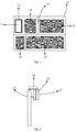
- Fig. 1 shows a structure diagram 1 of a terminal with internal heat-dissipation function according to the embodiment of the disclosure.
- the terminal with internal heat-dissipation function includes at least one cavity 11 in which heat-storage material is arranged, and the cavity 11 is located in an area without a device in the terminal.
- a plurality of devices 14 are arranged on a PCB 13 in the terminal.
- the devices 14 are isolated from each other by a first shield frame 15.
- An area without a device in the terminal is the left upper area on the PCB 13.
- the first shield frame 15 is used for preventing generation of interference between the devices 14. Any structure would be sufficient for the first shield frame 13, as long as the interference can be shielded.
- the area without a device is designed as an enclosed cavity 11, and heat-storage material is arranged in the cavity 11 to absorb the heat generated by the devices 14 on the PCB 13.
- the cavity 11 is formed by the area without a device surrounded by a shield frame 12 which is arranged in the terminal.
- the shield frame 12 has an enclosed structure; the shield frame 12 and the area surrounded by the shield frame 12 are located in the area without a device on the PCB13 of the terminal.
- the shield frame 12 is a rectangular structure, and the shield frame 12 and the area surrounded by the shield frame 12 are located in the area without a device on the left upper part of the PCB 13 of the terminal.
- the area surrounded by the shield frame 12 is the designed cavity 11.
- the enclosed structure may be a hemispherical enclosed structure, a polyhedral enclosed structure and the like.
- the enclosed structure is used to guarantee the heat-storage material in the cavity 11 to be isolated from other devices 14, and thus the normal operation of the devices 14 will not be affected.
- the material of the shield frame 12 may be metal and/or metallic alloy and/or non-metallic material.
- the shield frame 12 and the first shield frame 15 may be made of the same material, or may be made of different materials.
- the shield frame 12 and the first shield frame 15 may be integrated on the PCB 13 by using the same material; then, the heat-storage material may be arranged inside the cavity 11 within the shield frame 12.
- the shield frame 12 since the shield frame 12 is an enclosed structure, the area surrounded by the shield frame 12 is isolated from the devices on the PCB13. In this way, the heat-storage material inside the cavity 11 is prevented from contacting the devices 14 on the PCB 13. Therefore, the heat-storage material inside the cavity 11 may be insulated material and/or non-insulated material.
- the heat-storage material may be phase-change heat-storage material, such as polycrystalline silicon.
- Fig. 2 shows a structure diagram 2 of a terminal with internal heat-dissipation function according to an embodiment of the disclosure.
- the terminal with internal heat-dissipation function includes at least one cavity 21 in which heat storage material is arranged; and the cavity 21 is located in an area without a device in the terminal.
- the cavity 21 is located in an area without a device between a PCB 22 and an antenna 23 in the terminal.
- an avoidance space reserved when designing the antenna serves as the cavity 21.
- the antenna 23 is fixed at a position away from the PCB 22 by a bracket 24. In this way, an area without a device exists between the PCB 22 and the antenna 23. The area without a device is the cavity 21.
- Heat-storage material is arranged inside the cavity 21 to absorb the heat generated by devices on the PCB 23.
- the bracket 24 is intended to prolong the distance between the antenna 23 and the PCB 22, so as to prevent the devices on the PCB 22 from affecting operation of the antenna 23.
- the area without a device between the antenna 23 and the PCB 22 forms the cavity 21, and thus the heat-storage material inside the cavity 21 will have no influence on the devices on the PCB 22.
- the heat-storage material absorbs and stores heat from the PCB 22 to lower the temperature of the PCB 22, thereby enabling the devices on the PCB 22 to operate normally.
- the heat-storage material may be phase-change heat-storage material, such as polycrystalline silicon, and the heat-storage material is insulated material. Therefore, interference between the heat-storage material and the antenna can be avoided.
- the terminals with internal heat-dissipation function provided by the embodiments of the disclosure make full use of the idle space in the terminal, and make the idle space a cavity capable of accommodating heat-storage material, and thus more heat-storage materials can be added into the cavity.
- the heat-storage capability of the terminal is substantially improved, and the time of duration of the terminal operating with high performance is prolonged.
- the internal heat-dissipation terminal provided by in the disclosure includes at least one cavity in which heat-storage material is arranged.
- the cavity is located in an area without a device in the terminal. In this way, the idle space in the terminal can be substantially used as a cavity to accommodate heat-storage material, and thus a great amount of heat-storage material can be arranged in the terminal, so as to substantially enhance the heat-storage capability of the terminal.
Landscapes
- Engineering & Computer Science (AREA)
- Microelectronics & Electronic Packaging (AREA)
- Physics & Mathematics (AREA)
- Thermal Sciences (AREA)
- Cooling Or The Like Of Electrical Apparatus (AREA)
- Connection Of Batteries Or Terminals (AREA)
- Secondary Cells (AREA)
Applications Claiming Priority (2)
| Application Number | Priority Date | Filing Date | Title |
|---|---|---|---|
| CN2013202240424U CN203279336U (zh) | 2013-04-27 | 2013-04-27 | 一种内散热的终端 |
| PCT/CN2013/081804 WO2013189373A2 (zh) | 2013-04-27 | 2013-08-19 | 一种内散热的终端 |
Publications (2)
| Publication Number | Publication Date |
|---|---|
| EP2991458A2 true EP2991458A2 (de) | 2016-03-02 |
| EP2991458A4 EP2991458A4 (de) | 2016-05-25 |
Family
ID=49509652
Family Applications (1)
| Application Number | Title | Priority Date | Filing Date |
|---|---|---|---|
| EP13807715.1A Withdrawn EP2991458A4 (de) | 2013-04-27 | 2013-08-19 | Endgerät mit einer interner wärmeableitung |
Country Status (4)
| Country | Link |
|---|---|
| US (1) | US10130010B2 (de) |
| EP (1) | EP2991458A4 (de) |
| CN (1) | CN203279336U (de) |
| WO (1) | WO2013189373A2 (de) |
Cited By (1)
| Publication number | Priority date | Publication date | Assignee | Title |
|---|---|---|---|---|
| WO2021252933A3 (en) * | 2020-06-12 | 2022-02-17 | Raytheon Company | Shape memory thermal capacitor and methods for same |
Family Cites Families (38)
| Publication number | Priority date | Publication date | Assignee | Title |
|---|---|---|---|---|
| US5075759A (en) * | 1989-07-21 | 1991-12-24 | Motorola, Inc. | Surface mounting semiconductor device and method |
| JP4108779B2 (ja) * | 1996-12-27 | 2008-06-25 | ローム株式会社 | 回路チップ搭載カードおよび回路チップモジュール |
| IL122250A (en) * | 1997-11-19 | 2003-07-31 | On Track Innovations Ltd | Smart card amenable to assembly using two manufacturing stages and a method of manufacture thereof |
| DE19835127A1 (de) * | 1998-08-04 | 2000-02-10 | Wuerth Elektronik Gmbh | Leiterplatte mit einem Heatsink und Verfahren zum Anbringen eines Heatsink |
| US6341062B1 (en) | 2000-03-06 | 2002-01-22 | International Business Machines Corp. | Thermal transfer hinge for hinged mobile computing device and method of heat transfer |
| CN1316858C (zh) * | 2001-04-27 | 2007-05-16 | 日本电气株式会社 | 高频电路基板及其制造方法 |
| US20020189853A1 (en) * | 2001-06-15 | 2002-12-19 | Phoenix Precision Technology Corp. | BGA substrate with direct heat dissipating structure |
| JP2003086728A (ja) * | 2001-07-05 | 2003-03-20 | Matsushita Electric Ind Co Ltd | 高周波回路の製作方法及びそれを用いた装置 |
| CN2770284Y (zh) | 2002-01-31 | 2006-04-05 | 王松 | 彩色显示屏电器的热源靠近外壳内壁散热与屏蔽的结构 |
| CN1458562A (zh) | 2002-01-31 | 2003-11-26 | 王松 | 彩色显示屏电器的热源靠近外壳内壁散热或屏蔽的方法 |
| CN1458561A (zh) | 2002-01-31 | 2003-11-26 | 王松 | 彩色显示屏电器的热源靠近外壳内壁散热或屏蔽的结构 |
| US7273987B2 (en) * | 2002-03-21 | 2007-09-25 | General Electric Company | Flexible interconnect structures for electrical devices and light sources incorporating the same |
| US6882537B2 (en) * | 2002-12-23 | 2005-04-19 | Eastman Kodak Company | Electrical assemblage and method for removing heat locally generated therefrom |
| US6930885B2 (en) * | 2002-12-23 | 2005-08-16 | Eastman Kodak Company | Densely packed electronic assemblage with heat removing element |
| CN1592566A (zh) | 2003-08-28 | 2005-03-09 | 王松 | 彩色显示屏电器的硬件结构 |
| CN1599549A (zh) | 2003-09-16 | 2005-03-23 | 王松 | 彩色显示屏电器热源的屏蔽和散热方法 |
| CN1878452A (zh) | 2005-06-10 | 2006-12-13 | 华为技术有限公司 | 一种移动终端的结构设计 |
| JP4857253B2 (ja) * | 2007-12-07 | 2012-01-18 | 株式会社日立製作所 | 画像表示装置 |
| US20110011939A1 (en) * | 2007-12-19 | 2011-01-20 | Linda Seah | Contact-less and dual interface inlays and methods for producing the same |
| US7742307B2 (en) * | 2008-01-17 | 2010-06-22 | Raytheon Company | High performance power device |
| US20110163348A1 (en) * | 2008-03-25 | 2011-07-07 | Bridge Semiconductor Corporation | Semiconductor chip assembly with bump/base heat spreader and inverted cavity in bump |
| US7842542B2 (en) * | 2008-07-14 | 2010-11-30 | Stats Chippac, Ltd. | Embedded semiconductor die package and method of making the same using metal frame carrier |
| US8269671B2 (en) * | 2009-01-27 | 2012-09-18 | International Business Machines Corporation | Simple radio frequency integrated circuit (RFIC) packages with integrated antennas |
| US8256685B2 (en) * | 2009-06-30 | 2012-09-04 | International Business Machines Corporation | Compact millimeter wave packages with integrated antennas |
| CN101707859A (zh) | 2009-11-30 | 2010-05-12 | 深圳华为通信技术有限公司 | 自然散热设备及提高设备散热能力的方法 |
| US8218337B2 (en) * | 2009-12-18 | 2012-07-10 | Intel Corporation | Apparatus and method for embedding components in small-form-factor, system-on-packages |
| CN101770563B (zh) | 2009-12-30 | 2011-11-02 | 华为终端有限公司 | 智能卡散热装置及其制造方法 |
| EP2355628B1 (de) | 2010-01-29 | 2013-10-16 | LG Electronics Inc. | Mobiles Endgerät |
| CN201709079U (zh) | 2010-05-26 | 2011-01-12 | 深圳Tcl新技术有限公司 | 屏蔽散热结构 |
| FR2963139B1 (fr) * | 2010-07-20 | 2012-09-14 | Oberthur Technologies | Dispositif a microcircuit comprenant des moyens d'amplification du gain d'une antenne |
| FR2963696B1 (fr) * | 2010-08-03 | 2012-09-21 | Oberthur Technologies | Dispositif a microcircuit comprenant un circuit d'antenne de communication en champ proche |
| FR2964487B1 (fr) * | 2010-09-02 | 2013-07-12 | Oberthur Technologies | Carte a microcircuit comprenant un moyen lumineux |
| US8339787B2 (en) | 2010-09-08 | 2012-12-25 | Apple Inc. | Heat valve for thermal management in a mobile communications device |
| US8957316B2 (en) * | 2010-09-10 | 2015-02-17 | Honeywell International Inc. | Electrical component assembly for thermal transfer |
| US8988299B2 (en) * | 2011-02-17 | 2015-03-24 | International Business Machines Corporation | Integrated antenna for RFIC package applications |
| CN202009411U (zh) | 2011-03-07 | 2011-10-12 | 海能达通信股份有限公司 | 一种手持通讯终端 |
| US9317079B2 (en) | 2011-03-29 | 2016-04-19 | Echostar Uk Holdings Limited | Media content device with customized panel |
| US8648454B2 (en) * | 2012-02-14 | 2014-02-11 | International Business Machines Corporation | Wafer-scale package structures with integrated antennas |
-
2013
- 2013-04-27 CN CN2013202240424U patent/CN203279336U/zh not_active Expired - Lifetime
- 2013-08-19 US US14/787,057 patent/US10130010B2/en active Active
- 2013-08-19 WO PCT/CN2013/081804 patent/WO2013189373A2/zh not_active Ceased
- 2013-08-19 EP EP13807715.1A patent/EP2991458A4/de not_active Withdrawn
Cited By (2)
| Publication number | Priority date | Publication date | Assignee | Title |
|---|---|---|---|---|
| WO2021252933A3 (en) * | 2020-06-12 | 2022-02-17 | Raytheon Company | Shape memory thermal capacitor and methods for same |
| US11558957B2 (en) | 2020-06-12 | 2023-01-17 | Raytheon Company | Shape memory thermal capacitor and methods for same |
Also Published As
| Publication number | Publication date |
|---|---|
| EP2991458A4 (de) | 2016-05-25 |
| WO2013189373A2 (zh) | 2013-12-27 |
| US10130010B2 (en) | 2018-11-13 |
| CN203279336U (zh) | 2013-11-06 |
| WO2013189373A3 (zh) | 2014-04-03 |
| US20160106002A1 (en) | 2016-04-14 |
Similar Documents
| Publication | Publication Date | Title |
|---|---|---|
| US11284537B2 (en) | Heat-conducting assembly and terminal | |
| US9046305B2 (en) | Phase change type heat dissipating device | |
| US20160266622A1 (en) | Mobile Terminal Heat Dissipation Apparatus and Shielding Cover Frame | |
| US9768096B2 (en) | Mobile terminal | |
| US9965003B2 (en) | Electronic assembly and electronic device | |
| CN108617082A (zh) | 一种散热组件以及电子装置 | |
| CN102548365A (zh) | 一种高散热性能的移动终端 | |
| CN213694596U (zh) | 电路板结构及电子设备 | |
| CN106231780A (zh) | Pcb板及具有其的移动终端 | |
| US10130010B2 (en) | Internal heat-dissipation terminal | |
| JP6266781B2 (ja) | 移動端末及びその液体金属の放熱方法 | |
| CN206302665U (zh) | 移动终端的后壳及移动终端 | |
| EP3916934B1 (de) | Lasermodul und elektronische vorrichtung | |
| CN108617158A (zh) | 一种散热组件以及电子装置 | |
| CN112994411A (zh) | 一种电源适配器散热结构 | |
| US20170042018A1 (en) | Dual Layer Shielding Cover and Terminal | |
| CN110636701A (zh) | 电路板装置及电子设备 | |
| US9674987B2 (en) | Heat dissipation device | |
| CN104159391A (zh) | 一种用于终端的散热装置及终端 | |
| CN204761484U (zh) | 智能半导体手机散热装置 | |
| CN205356936U (zh) | 一种箱体散热结构及应急指挥箱 | |
| CN211266866U (zh) | 一种抗风扰晶体振荡器 | |
| CN208113225U (zh) | 一种屏蔽罩、散热组件及电子设备 | |
| JP2013214605A (ja) | 携帯端末機器 | |
| CN209593925U (zh) | 电子设备的电路板组件及电子设备 |
Legal Events
| Date | Code | Title | Description |
|---|---|---|---|
| PUAI | Public reference made under article 153(3) epc to a published international application that has entered the european phase |
Free format text: ORIGINAL CODE: 0009012 |
|
| 17P | Request for examination filed |
Effective date: 20151127 |
|
| AK | Designated contracting states |
Kind code of ref document: A2 Designated state(s): AL AT BE BG CH CY CZ DE DK EE ES FI FR GB GR HR HU IE IS IT LI LT LU LV MC MK MT NL NO PL PT RO RS SE SI SK SM TR |
|
| AX | Request for extension of the european patent |
Extension state: BA ME |
|
| A4 | Supplementary search report drawn up and despatched |
Effective date: 20160426 |
|
| RIC1 | Information provided on ipc code assigned before grant |
Ipc: H05K 1/02 20060101AFI20160420BHEP |
|
| DAX | Request for extension of the european patent (deleted) | ||
| 17Q | First examination report despatched |
Effective date: 20190320 |
|
| STAA | Information on the status of an ep patent application or granted ep patent |
Free format text: STATUS: THE APPLICATION HAS BEEN WITHDRAWN |
|
| 18W | Application withdrawn |
Effective date: 20190424 |