EP2991450A1 - Garsystem - Google Patents
Garsystem Download PDFInfo
- Publication number
- EP2991450A1 EP2991450A1 EP15181321.9A EP15181321A EP2991450A1 EP 2991450 A1 EP2991450 A1 EP 2991450A1 EP 15181321 A EP15181321 A EP 15181321A EP 2991450 A1 EP2991450 A1 EP 2991450A1
- Authority
- EP
- European Patent Office
- Prior art keywords
- cooking
- container
- muffle
- cooking system
- cooking container
- Prior art date
- Legal status (The legal status is an assumption and is not a legal conclusion. Google has not performed a legal analysis and makes no representation as to the accuracy of the status listed.)
- Granted
Links
Images

Classifications
-
- H—ELECTRICITY
- H05—ELECTRIC TECHNIQUES NOT OTHERWISE PROVIDED FOR
- H05B—ELECTRIC HEATING; ELECTRIC LIGHT SOURCES NOT OTHERWISE PROVIDED FOR; CIRCUIT ARRANGEMENTS FOR ELECTRIC LIGHT SOURCES, IN GENERAL
- H05B6/00—Heating by electric, magnetic or electromagnetic fields
- H05B6/64—Heating using microwaves
- H05B6/6408—Supports or covers specially adapted for use in microwave heating apparatus
-
- A—HUMAN NECESSITIES
- A47—FURNITURE; DOMESTIC ARTICLES OR APPLIANCES; COFFEE MILLS; SPICE MILLS; SUCTION CLEANERS IN GENERAL
- A47J—KITCHEN EQUIPMENT; COFFEE MILLS; SPICE MILLS; APPARATUS FOR MAKING BEVERAGES
- A47J27/00—Cooking-vessels
- A47J27/04—Cooking-vessels for cooking food in steam; Devices for extracting fruit juice by means of steam ; Vacuum cooking vessels
-
- A—HUMAN NECESSITIES
- A47—FURNITURE; DOMESTIC ARTICLES OR APPLIANCES; COFFEE MILLS; SPICE MILLS; SUCTION CLEANERS IN GENERAL
- A47J—KITCHEN EQUIPMENT; COFFEE MILLS; SPICE MILLS; APPARATUS FOR MAKING BEVERAGES
- A47J36/00—Parts, details or accessories of cooking-vessels
- A47J36/02—Selection of specific materials, e.g. heavy bottoms with copper inlay or with insulating inlay
- A47J36/027—Cooking- or baking-vessels specially adapted for use in microwave ovens; Accessories therefor
-
- H—ELECTRICITY
- H05—ELECTRIC TECHNIQUES NOT OTHERWISE PROVIDED FOR
- H05B—ELECTRIC HEATING; ELECTRIC LIGHT SOURCES NOT OTHERWISE PROVIDED FOR; CIRCUIT ARRANGEMENTS FOR ELECTRIC LIGHT SOURCES, IN GENERAL
- H05B6/00—Heating by electric, magnetic or electromagnetic fields
- H05B6/64—Heating using microwaves
- H05B6/6402—Aspects relating to the microwave cavity
-
- H—ELECTRICITY
- H05—ELECTRIC TECHNIQUES NOT OTHERWISE PROVIDED FOR
- H05B—ELECTRIC HEATING; ELECTRIC LIGHT SOURCES NOT OTHERWISE PROVIDED FOR; CIRCUIT ARRANGEMENTS FOR ELECTRIC LIGHT SOURCES, IN GENERAL
- H05B6/00—Heating by electric, magnetic or electromagnetic fields
- H05B6/64—Heating using microwaves
- H05B6/647—Aspects related to microwave heating combined with other heating techniques
-
- H—ELECTRICITY
- H05—ELECTRIC TECHNIQUES NOT OTHERWISE PROVIDED FOR
- H05B—ELECTRIC HEATING; ELECTRIC LIGHT SOURCES NOT OTHERWISE PROVIDED FOR; CIRCUIT ARRANGEMENTS FOR ELECTRIC LIGHT SOURCES, IN GENERAL
- H05B6/00—Heating by electric, magnetic or electromagnetic fields
- H05B6/64—Heating using microwaves
- H05B6/647—Aspects related to microwave heating combined with other heating techniques
- H05B6/6473—Aspects related to microwave heating combined with other heating techniques combined with convection heating
- H05B6/6479—Aspects related to microwave heating combined with other heating techniques combined with convection heating using steam
-
- A—HUMAN NECESSITIES
- A47—FURNITURE; DOMESTIC ARTICLES OR APPLIANCES; COFFEE MILLS; SPICE MILLS; SUCTION CLEANERS IN GENERAL
- A47J—KITCHEN EQUIPMENT; COFFEE MILLS; SPICE MILLS; APPARATUS FOR MAKING BEVERAGES
- A47J27/00—Cooking-vessels
- A47J27/04—Cooking-vessels for cooking food in steam; Devices for extracting fruit juice by means of steam ; Vacuum cooking vessels
- A47J2027/043—Cooking-vessels for cooking food in steam; Devices for extracting fruit juice by means of steam ; Vacuum cooking vessels for cooking food in steam
Definitions
- the present invention relates to a cooking system with a cooking appliance and at least one cooking container for receiving food.
- the cooking appliance comprises at least one microwave heating source.
- the cooking appliance has at least one cooking chamber with at least one muffle and at least one carrying device arranged on the muffle for positioning the cooking container in the cooking chamber.
- Cooking appliances usually have one or more heat sources for the preparation of food in a cooking chamber.
- a combination of different heat sources is often particularly useful because the heat sources then complement each other in their advantages.
- a MikrowellenloomISE a very good efficiency, since the energy of the microwaves is immediately available and the food is cooked from the inside.
- Steam heat sources for example, allow a particularly gentle cooking and prevent the drying of food during cooking.
- the combination of different heat sources presents a technical challenge, in particular with so-called combined appliances with a microwave heat source and a thermal heat source.
- the cooking chamber must be heat-resistant to the expected temperatures during operation of the thermal heat source together with the used cooking containers.
- microwave heating sources it must be taken into account that unfavorable heaters and flashovers do not occur due to the power supply.
- cooking containers have become known, which are made of plastic or ceramic.
- metal cooking containers have also become known, but manufacturers prohibit their use in microwave mode.
- metallic cooking containers have become known, which are accommodated in a tray cart, so that the distance to the cooking chamber is very large. The disadvantage of this is the very high space requirement, so that such solutions are not considered in the narrow dimensions of a household appliance.
- the cooking system comprises at least one cooking appliance and at least one cooking container for receiving food.
- the cooking appliance has at least one microwave heating source and at least one cooking chamber with at least one muffle.
- At least one carrying device for positioning the cooking container in the cooking chamber is provided on the muffle.
- the cooking container comprises at least one bottom and at least four side walls arranged transversely to the bottom. It is possible that at least one side wall is at least partially formed by a door.
- the side walls comprise at least two opposite longitudinal sides and at least two opposite broad sides. In this case, the cooking container at transitions from the broad side to the longitudinal side at least 4 corners.
- the corners are designed to maintain a minimum distance from the muffle with at least one rounding.
- the rounding has at least an outer radius of at least 30 mm.
- the cooking system according to the invention has many advantages.
- a considerable advantage is that at least one cooking appliance and at least one cooking container are provided, wherein the cooking container has rounded portions with an outer radius of at least 30 mm.
- Such a minimum radius ensures that a sufficient minimum distance between the cooking container and the cooking chamber can always be maintained. Smaller radii would lead to the corners of the cooking container coming so close to the cooking chamber that flashover may occur.
- the cooking container according to the invention can be easily designed from a metallic material, without that during normal operation voltage flashovers occur in a microwave operation.
- Another advantage of the cooking system is that the available cooking space can be optimally used. Since voltage flashovers are already reliably prevented by the rounded corners, a correspondingly close reception of the cooking container in the cooking chamber can take place. Through such optimal use of space, the cooking system is particularly advantageous in household use.
- the rounding of the corners also offers hygienic advantages, since such cooking containers can be cleaned and kept clean very uncomplicated. This is advantageous, for example, compared with prior art cooking containers, which roll up the container rim in a complex manner in order to avoid flashovers. Such rolled up areas are usually very difficult to keep clean.
- those inventively provided rounding can be inexpensively implemented with the appropriate radius in the production and thus produced inexpensively.
- the rounding has at least an outer radius of at least 30 mm to counteract electrical flashovers between cooking container and cooking chamber.
- the outer radius of the rounding is at least 35 mm. With such a radius, the occurrence of electric flashovers can be more effectively prevented.
- the minimum distance between the cooking container and muffle is at least 8 mm. Particularly preferably, the minimum distance is at least 10 mm. Such a minimum distance ensures reliable rollover protection and at the same time offers optimum space utilization for the cooking container in the cooking chamber. It is provided in particular that the minimum distance is maintained regardless of the positioning of the cooking container on the support means. In particular, while the outer radius of the rounding is tuned to the required minimum distance. For example, a minimum distance of at least 10 mm can be achieved particularly well in a rounding with an outer radius of more than 35 mm. In particular, the minimum distance is maintained even when the cooking container is arranged in a tilted and / or slightly oblique position on the support means.
- the rounded portions are formed on at least one container edge.
- the container edge is arranged in particular on at least one side wall.
- the container edge comprises at least one end edge protruding outwards from the broad side.
- the container edge may also include at least one side edge projecting outwardly from the longitudinal side.
- Such a container edge can serve particularly well for guiding the cooking container in the carrying device.
- the rounded edges formed on the edge of the container reliably prevent it from falling below the minimum distance to the muffle, in particular even when the cooking container is guided at least somewhat tilted.
- the container edge comprises at least one end edge arranged transversely to the broad side and / or at least one side edge arranged transversely to the longitudinal side.
- the end edge and / or the side edge preferably extend substantially parallel to the bottom of the cooking container.
- the front edge is formed in particular narrower than 20 mm.
- the end edge is narrower than 12 mm formed.
- the end edge is more ready than 3 mm and preferably wider than 5 mm formed. It is also possible that no front edge is provided.
- the volume of the cooking chamber can be optimally utilized. In addition, this does not unnecessarily limit the area of the cooking container intended for the food to be cooked.
- the support device has at least one horizontally extending rod.
- at least two rods are provided.
- the rods are arranged in particular at the same height on opposite sides of the muffle. It is also possible that two opposite bars are provided at different heights in the cooking chamber. Two bars each characterize an insertion position for the cooking container.
- the rod is particularly suitable and adapted to serve as a guide for the side edge. In this case, the side edge is in particular at least partially on the rod.
- the rod has a diameter of at least 3 mm and preferably of at least 4 mm.
- a clearance between the rod and at least one of the longitudinal sides is a maximum of 4 mm.
- the game is a maximum of 2.5 mm.
- the carrying device has at least one stop for the rounding.
- the stop is particularly suitable and designed to limit a depth of insertion of the cooking vessel in the cooking chamber.
- the stop can also be provided for a side wall and / or the container edge.
- the stop is designed as a cross member.
- the transverse strut in this case runs in particular transversely to at least one bar which is provided for guiding the side edge of the cooking container. Such a stop effectively prevents the cooking container abuts with a broad side against the rear cooking chamber wall, which arcing may occur.
- the side walls have a height of at least 30 mm.
- the height of the side walls is at least 40 mm.
- the corners each have at least one rounding with an inner radius of at most 30 mm.
- the inner radius is preferably less than 24 mm.
- the cooking container has a width which is at most 3 times a depth.
- the width extends along the broad side and the depth along the longitudinal side.
- the width and depth are in a ratio of approximately 2: 1.
- the width of the cooking vessel is 325 mm and the depth is 170 mm.
- the support device is arranged electrically isolated on the muffle.
- at least one insulating body is provided between a rod and the muffle.
- the rod is inserted into a recess of the muffle, wherein the rod is surrounded by an insulating sleeve.
- An insulating recording avoids voltage peaks. But it is also possible that the support means is electrically contacted with the muffle.
- the cooking appliance is designed as a combi appliance with a steaming function and a microwave cooking function.
- at least one steam heating source and at least one microwave heating source are provided.
- the advantages of the previously described cooking vessel can be used particularly well.
- the cooking container in a metallic version is particularly well suited for holding food during a steam cooking process and on the other hand it can be used in microwave mode without fear of flashovers.
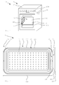
- an inventive cooking system 100 is shown with a cooking appliance 1 and a cooking container 2 accommodated in a cooking chamber 3 of the cooking appliance 1.
- the cooking appliance 1 can be operated by a user via an operating device 104 and has a cooking chamber 3 for the treatment of food.
- the cooking chamber 3 can be closed by means of a door 105 become.
- the cooking appliance 1 here has a microwave heating source 11 and a steam generator 10 shown schematically.
- Other thermal heat sources may be provided, such. B. top and bottom heat or a Um KunststoffLiteteilán. Different heat sources can be operated individually or in any combination.
- the cooking appliance 1 can be designed both as a built-in appliance and as a stand-alone cooking appliance 1.
- the cooking appliance 1 is designed as a combined appliance 21.
- the cooking chamber 3 is surrounded here by a muffle 13, which together with the door 105 prevents leakage of microwaves and substantially also of steam.
- the door 105 can be opened by a door opener.
- At least one safety device is provided which prevents microwave operation when the door 105 is not properly closed.
- a support device 4 is arranged at the muffle 13 for positioning of the cooking container 2 and other food support such.
- the support means 4 consists here of two attached to opposite side surfaces of the muffle 13 support grids.
- the support grid consists of several rods which are arranged in the longitudinal or in the transverse direction and connected to each other. In this case, one or more cooking containers 2 can be inserted in different height positions along the longitudinal bars.
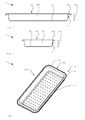
- the cooking container 2 is in an exemplary embodiment in FIG. 2 in a top view and in the FIGS. 3 and 4 shown in a longitudinal or cross-sectional side view.
- the FIG. 5 shows the cooking container 2 in a perspective view.
- the cooking container 2 has a bottom 12 with a plurality of holes for improving the steam passage.
- a total of 4 interconnected side walls 22 are arranged.
- the side walls 22 are arranged at an angle slightly greater than 90 ° to the bottom 12 in order to be able to more easily remove a food item from the cooking container 2.
- two opposite side walls 22 are formed as broad sides 222 and as longitudinal sides 221.
- the broad side extends over a width 224, which is 375 mm by way of example here.
- the container edge 52 is formed on the broad side 222 as an outwardly projecting end edge 522.
- an outwardly projecting side edge 521 is arranged.
- the side edge 521 and the end edge 522 are z. B. 10 mm wide.
- the cooking container 2 here corners 32, which are provided with rounded portions 42.
- the rounded portions 42 have an outer radius of at least 35 mm.
- the side walls 22 have a height 220 of 40 mm.
- At the corners 32 are inner radii of max. 24 mm. intended.
- FIG. 6 shows a detail of a plan view of a detail of a cooking vessel 2, which is accommodated in a cooking chamber 3 on a support means 4.
- the carrying device 4 comprises a rod 14, on which the inserted cooking container 2 rests.
- the rod 14 is electrically isolated in a recess of a muffle 13 of the cooking chamber 3 attached. Between the cooking container 2 and the muffle 13 an exemplary minimum distance of 15 mm is maintained here, so that no electrical flashovers occur in microwave operation.
- the FIG. 7 shows the cooking container 2 the FIG. 6 in a tilted position. Due to the rounding with an outer radius of here, for example, 40 mm, the required minimum distance 5 is not undershot even in this tilted position to protect against flashovers. In this case, the side edge 521 of the cooking container 2 rests on the rod 14.
- the cooking system 100 presented here enables the use of metallic cooking containers 2 and in particular stainless steel containers in microwave operation at low cost and hygienic safety as well as with a large work surface.
- the construction of the cooking container 2 ensures that always a minimum distance 5 between the cooking container 2 and cooking chamber 3 is maintained. This is achieved in particular by the rounding of the Gar actuallyerecken 32 and the ratio of depth 223 to the width 224.
- Gar actuallyer 2 and cooking chamber 3 also an accurate and stable leadership of the cooking vessel 2 is ensured by a close match between the cooking container 2 and carrying device 4 present, the cooking container 2 has small inner radii and the rods 14 of the support means 4 have a sufficiently large diameter.
Landscapes
- Physics & Mathematics (AREA)
- Electromagnetism (AREA)
- Engineering & Computer Science (AREA)
- Food Science & Technology (AREA)
- Cookers (AREA)
- Electric Ovens (AREA)
Abstract
Description
- Die vorliegende Erfindung betrifft ein Garsystem mit einem Gargerät und wenigstens einem Garbehälter zur Aufnahme von Gargut. Das Gargerät umfasst wenigstens eine Mikrowellenheizquelle. Das Gargerät weist wenigstens einen Garraum mit wenigstens einer Muffel und wenigstens eine an der Muffel angeordnete Trageinrichtung zur Positionierung des Garbehälters im Garraum auf.
- Gargeräte weisen in der Regel eine oder mehrere Heizquellen für die Zubereitung von Speisen in einem Garraum auf. Dabei ist eine Kombination verschiedener Heizquellen oft besonders sinnvoll, da sich die Heizquellen dann in ihren Vorteilen ergänzen. So bietet z.B. eine Mikrowellenheizquelle einen sehr guten Wirkungsgrad, da die Energie der Mikrowellen sofort zur Verfügung steht und das Lebensmittel von innen her gegart wird. Dampfheizquellen ermöglichen beispielsweise eine besonders schonende Garung und verhindern das Austrocknen von Lebensmitteln beim Garen.
- Die Kombination verschiedener Heizquellen stellt insbesondere bei sogenannten Kombigeräten mit einer Mikrowellenheizquelle und einer thermischen Heizquelle eine technische Herausforderung dar. Einerseits muss bei einem solchen Kombigerät der Garraum zusammen mit den verwendeten Garbehältern hitzebeständig gegenüber den zu erwartenden Temperaturen beim Betrieb der thermischen Heizquelle sein. Andererseits muss bei der Verwendung von Mikrowellenheizquellen berücksichtigt werden, dass es aufgrund der Leistungszufuhr nicht zu ungünstigen Erwärmungen und Spannungsüberschlägen kommt.
- Besonders bei der Gestaltung von Garbehältern für solche Kombigeräte sollte beachtet werden, dass es nicht zu Überschlägen zwischen Garbehälter und Garraum kommt. Denn solche Überschläge können den Garbehälter optisch beeinträchtigen oder gar beschädigen und auch den Garraummantel in Mitleidenschaft ziehen.
- Im Stand der Technik sind daher Garbehälter bekannt geworden, welche aus Kunststoff oder Keramik gestaltet sind. Zudem sind auch Garbehälter aus Metall bekannt geworden, bei denen die Hersteller aber eine Verwendung im Mikrowellenbetrieb untersagen. Bei gewerblichen Geräten sind metallische Garbehälter bekannt geworden, welche in einem Hordenwagen aufgenommen sind, sodass der Abstand zum Garraum sehr groß ist. Nachteilig daran ist der sehr hohe Platzbedarf, sodass solche Lösungen bei den engen Abmessungen eines Haushaltsgerätes nicht in Betracht kommen.
- Es ist daher die Aufgabe der vorliegenden Erfindung ein Gargerät und einen Garbehälter zur Verfügung zu stellen, die eine verbesserte Eignung für einen Mikrowellenbetrieb und insbesondere für einen Kombibetrieb mit einer Mikrowellenheizquelle und einer thermischen Heizquelle aufweisen.
- Diese Aufgabe wird durch ein Garsystem mit den Merkmalen des Anspruchs 1 gelöst. Einige Vorteile und Merkmale der vorliegenden Erfindung ergeben sich aus den Unteransprüchen. Weitere Vorteile und Merkmale sind in der allgemeinen Beschreibung und der Beschreibung des Ausführungsbeispiels angegeben.
- Das erfindungsgemäße Garsystem umfasst wenigstens ein Gargerät und wenigstens einen Garbehälter zur Aufnahme von Gargut. Das Gargerät weist wenigstens eine Mikrowellenheizquelle und wenigstens einen Garraum mit wenigstens einer Muffel auf. An der Muffel ist wenigstens eine Trageinrichtung zur Positionierung des Garbehälters im Garraum vorgesehen. Der Garbehälter umfasst wenigstens einen Boden und wenigstens 4 quer zum Boden angeordnete Seitenwände. Es ist möglich, dass wenigstens eine Seitenwand wenigstens teilweise durch eine Tür gebildet wird. Die Seitenwände umfassen wenigstens zwei gegenüberliegende Längsseiten und wenigstens zwei gegenüberliegende Breitseiten. Dabei weist der Garbehälter an Übergängen von der Breitseite zur Längsseite wenigstens 4 Ecken auf. Die Ecken sind dabei zur Einhaltung eines Mindestabstandes zur Muffel mit jeweils wenigstens einer Abrundung ausgebildet. Die Abrundung weist dabei wenigstens einen Außenradius von wenigstens 30 mm auf. Hierdurch wird elektrischen Überschlägen zwischen Garbehälter und Garraum entgegengewirkt und die Eignung von Gargerät und/oder Garbehälter für einen Mikrowellenbetrieb verbessert. Das erfindungsgemäße Garsystem hat viele Vorteile. Ein erheblicher Vorteil ist, dass wenigstens ein Gargerät und wenigstens ein Garbehälter vorgesehen sind, wobei der Garbehälter Abrundungen mit einem Außenradius von wenigstens 30 mm aufweist. Durch einen solchen Mindestradius wird gewährleistet, dass immer ein ausreichender Mindestabstand zwischen dem Garbehälter und dem Garraum eingehalten werden kann. Kleinere Radien würden dabei dazu führen, dass die Ecken des Garbehälters dem Garraum so nahe kommen, sodass Spannungsüberschläge auftreten können. Dadurch kann der erfindungsgemäße Garbehälter problemlos aus einem metallischen Material gestaltet werden, ohne dass im Regelbetrieb Spannungsüberschläge bei einem Mikrowellenbetrieb auftreten.
- Ein weiterer Vorteil des Garsystems ist, dass der zur Verfügung stehende Garraum optimal genutzt werden kann. Da durch die abgerundeten Ecken Spannungsüberschläge bereits zuverlässig vermieden werden, kann eine entsprechend enge Aufnahme des Garbehälters im Garraum erfolgen. Durch eine solche optimale Raumausnutzung ist das Garsystem besonders vorteilhaft im Haushaltsbereich einsetzbar.
- Das Abrunden der Ecken bietet dabei auch hygienische Vorteile, da solche Garbehälter auch sehr unkompliziert gereinigt und sauber gehalten werden können. Das ist beispielsweise gegenüber Garbehältern aus dem Stand der Technik vorteilhaft, welche den Behälterrand in aufwändiger Weise einrollen, um Überschläge zu vermeiden. Solche eingerollten Bereiche sind aber in der Regel sehr schwer sauber zu halten. Zudem können solche die erfindungsgemäß vorgesehenen Abrundungen mit dem entsprechenden Radius in der Herstellung unaufwändig umgesetzt und somit kostengünstig hergestellt werden.
- Die Abrundung weist dabei wenigstens einen Außenradius von wenigstens 30 mm auf, um elektrischen Überschlägen zwischen Garbehälter und Garraum entgegen zu wirken.
- In einer bevorzugten Weiterbildung beträgt der Außenradius der Abrundung wenigstens 35 mm. Mit einem solchen Radius kann das Auftreten von elektrischen Überschlägen noch wirkungsvoller verhindert werden.
- In einer anderen bevorzugten Weiterbildung beträgt der Mindestabstand zwischen Garbehälter und Muffel wenigstens 8 mm. Besonders bevorzugt beträgt der Mindestabstand wenigstens 10 mm. Ein solcher Mindestabstand gewährleistet einen zuverlässigen Überschlagsschutz und bietet zugleich eine optimale Raumausnutzung für den Garbehälter im Garraum. Dabei ist insbesondere vorgesehen, dass der Mindestabstand unabhängig von der Positionierung des Garbehälters an der Trageinrichtung eingehalten wird. Insbesondere ist dabei der Außenradius der Abrundung auf den erforderlichen Mindestabstand abgestimmt. Beispielsweise kann ein Mindestabstand von wenigstens 10 mm besonders gut bei einer Abrundung mit einem Außenradius von mehr als 35 mm erreicht werden. Insbesondere wird der Mindestabstand auch dann eingehalten, wenn der Garbehälter in einer verkanteten und/oder leicht schrägen Stellung an der Trageinrichtung angeordnet ist.
- Vorzugsweise sind die Abrundungen an wenigstens einem Behälterrand ausgebildet. Der Behälterrand ist dabei insbesondere an wenigstens einer Seitenwand angeordnet. Insbesondere umfasst der Behälterrand wenigstens einen nach außen von der Breitseite abstehenden Stirnrand. Der Behälterrand kann auch wenigstens einen nach außen von der Längsseite abstehenden Seitenrand umfassen. Ein solcher Behälterrand kann besonders gut zur Führung des Garbehälters in der Trageinrichtung dienen. Die dabei an dem Behälterrand ausgebildeten Abrundungen verhindern zuverlässig eine Unterschreitung des Mindestabstands zur Muffel insbesondere sogar auch dann, wenn der Garbehälter wenigstens etwas verkantet geführt wird. Insbesondere umfasst der Behälterrand wenigstens einen quer zur Breitseite angeordneten Stirnrand und/oder wenigstens einen quer zur Längsseite angeordneten Seitenrand. Der Stirnrand und/oder der Seitenrand erstrecken sich vorzugsweise im Wesentlichen parallel zum Boden des Garbehälters. Der Stirnrand ist insbesondere schmaler als 20 mm ausgebildet. Vorzugsweise ist der Stirnrand schmaler als 12 mm ausgebildet. Insbesondere ist der Stirnrand bereiter als 3 mm und vorzugsweise breiter als 5 mm ausgebildet. Möglich ist auch, dass gar kein Stirnrand vorgesehen ist. Durch solche Ausgestaltungen kann das Volumen des Garraums optimal ausgenutzt werden. Zudem wird dadurch der für das Gargut vorgesehene Bereich des Garbehälters nicht unnötig eingeschränkt.
- In einer vorteilhaften Weiterbildung weist die Trageinrichtung wenigstens einen horizontal verlaufenden Stab auf. Insbesondere sind wenigstens zwei Stäbe vorgesehen. Die Stäbe sind dabei insbesondere auf gleicher Höhe an gegenüberliegenden Seiten der Muffel angeordnet. Möglich ist auch, dass auf unterschiedlichen Höhen im Garraum jeweils zwei sich gegenüberliegende Stäbe vorgesehen sind. Dabei charakterisieren jeweils zwei Stäbe eine Einschubposition für den Garbehälter. Der Stab ist insbesondere dazu geeignet und ausgebildet, als Führung für den Seitenrand zu dienen. Dabei liegt der Seitenrand insbesondere wenigstens teilweise auf den Stab auf. Der Stab weist insbesondere einen Durchmesser von wenigstens 3 mm und vorzugsweise von wenigstens 4 mm auf. Durch einen solchen Durchmesser kann ein Durchbiegen der Stäbe auch bei schwerbeladenen Garbehältern zuverlässig vermieden werden.
- Besonders bevorzugt beträgt ein Spiel zwischen dem Stab und wenigstens einer der Längsseiten maximal 4 mm. Bevorzugt beträgt das Spiel maximal 2,5 mm. Durch ein solches geringes Spiel wird ein Verkanten des Garbehälters in der Trageinrichtung wirkungsvoll verhindert. Zudem wird durch das geringe Spiel ein Unterschreiten des Mindestabstandes verhindert.
- Es ist möglich, dass die Trageinrichtung wenigstens einen Anschlag für die Abrundung aufweist. Dabei ist der Anschlag insbesondere dazu geeignet und ausgebildet, eine Einschubtiefe des Garbehälters in den Garraum zu begrenzen. Der Anschlag kann dabei auch für eine Seitenwand und/oder den Behälterrand vorgesehen sein. Beispielsweise ist der Anschlag als Querstrebe ausgebildet. Die Querstrebe verläuft dabei insbesondere quer zu wenigstens einem Stab, der zur Führung des Seitenrandes des Garbehälters vorgesehen ist. Ein solcher Anschlag verhindert wirkungsvoll das der Garbehälter mit einer Breitseite gegen die hintere Garraumwand stößt, wobei Überschläge auftreten können.
- Vorzugsweise weisen die Seitenwände eine Höhe von wenigstens 30 mm auf. Besonders bevorzugt beträgt die Höhe der Seitenwände wenigstens 40 mm.
- Insbesondere weisen die Ecken jeweils wenigstens eine Abrundung mit einem Innenradius von maximal 30 mm auf. Der Innenradius beträgt bevorzugt weniger als 24 mm. Durch die Berücksichtigung solcher Maße für den Innenradius kann dem Auftreten von Spannungsspitzen zuverlässig entgegengewirkt werden.
- Es ist bevorzugt, dass der Garbehälter eine Breite aufweist, welche maximal das 3-fache einer Tiefe beträgt. Die Breite erstreckt sich dabei entlang der Breitseite und die Tiefe entlang der Längsseite. Insbesondere stehen Breite und Tiefe dabei in einem Verhältnis von etwa 2 : 1. Beispielsweise beträgt die Breite des Garbehälters 325 mm und die Tiefe 170 mm. Ein solches Verhältnis von Breite zu Tiefe verhindert wirkungsvoll ein Durchbiegen der Stäbe der Trageinrichtung auch bei sehr beladenen Garbehältern.
- Vorzugsweise ist die Trageinrichtung elektrisch isoliert an der Muffel angeordnet. Insbesondere ist dabei zwischen einem Stab und der Muffel wenigstens ein Isolierkörper vorgesehen. Beispielsweise ist der Stab in eine Ausnehmung der Muffel eingesteckt, wobei der Stab dabei von einer isolierenden Hülse umgeben ist. Durch eine isolierende Aufnahme werden Spannungsspitzen vermieden. Möglich ist aber auch, dass die Trageinrichtung mit der Muffel elektrisch kontaktiert ist.
- In einer besonders bevorzugten Ausgestaltung ist das Gargerät als ein Kombigerät mit einer Dampfgarfunktion und einer Mikrowellengarfunktion ausgebildet. Dazu sind wenigstens eine Dampfheizquelle und wenigstens eine Mikrowellenheizquelle vorgesehen. Bei einem solchen Kombigerät können die Vorteile des zuvor beschriebenen Garbehälters besonders gut genutzt werden. Einerseits eignet sich der Garbehälter in einer metallischen Ausführung besonders gut zur Aufnahme von Gargut während eines Dampfgarprozesses und zum anderen kann er im Mikrowellenbetrieb eingesetzt werden, ohne Spannungsüberschläge befürchten zu müssen.
- In den Figuren zeigen:
- Figur 1
- eine schematische perspektivische Ansicht des Garsystems 100;
- Figur 2
- eine schematische Draufsicht auf einen Garbehälter des Garsystems nach
Fig 1 ; - Figur 3
- einen Längsschnitt des Garbehälters nach
Fig. 2 ; - Figur 4
- einen Querschnitt des Garbehälters nach
Fig. 2 ; - Figur 5
- eine perspektivische Ansicht des Garbehälters nach
Fig. 2 ; - Figur 6
- einen vergrößerten Außenschnitt eines Garbehälters in einem Garraum; und
- Figur 7
- den Außenschnitt nach
Fig. 6 mit einem verkantet eingesetzten Garbehälter. - In der
Figur 1 ist ein erfindungsgemäßes Garsystem 100 mit einem Gargerät 1 und einem in einem Garraum 3 des Gargerätes 1 aufgenommenem Garbehälter 2 dargestellt. Das Gargerät 1 kann von einem Benutzer über eine Bedieneinrichtung 104 bedient werden und hat einen Garraum 3 zur Behandlung von Gargut. Der Garraum 3 kann mittels einer Tür 105 verschlossen werden. Zum Erwärmen, bzw. Erhitzen des Garguts weist das Gargerät 1 hier eine Mikrowellenheizquelle 11 und einen schematisch dargestellten Dampferzeuger 10 auf. Weitere thermische Heizquellen können vorgesehen sein, wie z. B. Ober- und Unterhitzeheizkörper oder eine Umluftheizquelle. Dabei können verschiedenen Heizquellen einzeln oder auch in beliebiger Kombination betrieben werden. Das Gargerät 1 kann sowohl als Einbaugerät als auch als alleistehendes Gargerät 1 ausgebildet sein. Hier ist das Gargerät 1 als ein Kombigerät 21 ausgeführt. - Der Garraum 3 ist hier von einer Muffel 13 umgeben, welche zusammen mit der Tür 105 ein Austreten von Mikrowellen und im Wesentlichen auch von Dampf verhindert. Die Tür 105 kann durch einen Türöffner geöffnet werden. Es ist wenigstens eine Sicherheitseinrichtung vorgesehen, welche einen Mikrowellenbetrieb bei nicht korrekt verschlossener Tür 105 verhindert.
- An der Muffel 13 ist zur Positionierung des Garbehälters 2 sowie auch anderer Gargutträger wie z. B. Backblechen oder Gitterrosten, eine Trageinrichtung 4 angeordnet. Die Trageinrichtung 4 besteht hier aus zwei an gegenüberliegenden Seitenflächen der Muffel 13 befestigten Traggittern. Das Traggitter besteht dabei aus mehreren Stäben, welche in Längs- bzw. in Querrichtung angeordnet und miteinander verbunden sind. Dabei können entlang der Längsstäbe ein oder mehrere Garbehälter 2 in verschiedenen Höhenpositionen eingeschoben werden.
- Der Garbehälter 2 ist in einer beispielhaften Ausführung in
Figur 2 in einer Draufsicht und in denFiguren 3 und 4 in einer längs- bzw. quergeschnittenen Seitenansicht dargestellt. DieFigur 5 zeigt den Garbehälter 2 in einer perspektivischen Darstellung. - Der Garbehälter 2 weist einen Boden 12 mit einer Vielzahl von Löchern zur Verbesserung des Dampfdurchlasses auf. Quer zum Boden 12 sind insgesamt 4 miteinander verbundene Seitenwände 22 angeordnet. Die Seitenwände 22 sind in einem Winkel etwas größer 90° zum Boden 12 angeordnet, um ein Gargut leichter aus dem Garbehälter 2 entnehmen zu können. Jeweils zwei gegenüberliegende Seitenwände 22 sind als Breitseiten 222 und als Längsseiten 221 ausgebildet. Die Breitseite erstreckt sich über eine Breite 224, welche hier beispielhaft 375 mm beträgt. Entlang der Längsseiten 221 ergibt sich eine Tiefe 223, welche hier beispielhaft 197 mm beträgt.
- Entlang der Seitenwände verläuft ein den Garbehälter 2 umgebender Behälterrand 52. Der Behälterrand 52 ist an der Breitseite 222 als ein nach außen abstehender Stirnrand 522 ausgebildet. Entlang der Längsseite 221 ist ein nach außen abstehender Seitenrand 521 angeordnet. Der Seitenrand 521 und der Stirnrand 522 sind z. B. 10 mm breit.
- Zur Gewährleistung eines Mindestabstandes zwischen Garbehälter 2 und Muffel 13 weist der Garbehälter 2 hier Ecken 32 auf, welche mit Abrundungen 42 versehen sind. Die Abrundungen 42 weisen dabei einen Außenradius von mindestens 35 mm auf. Die Seitenwände 22 weisen eine Höhe 220 von 40 mm auf. An den Ecken 32 sind Innenradien von max. 24 mm. vorgesehen. Durch einen derart ausgestalteten Innenradius der Behälterecken 32 kann eine genaue und stabile Führung des Garbehälters 2 in der Trageinrichtung 4 gewährleistet werden. Zudem werden Ecken vermieden, welche von sich aus ungünstige Spannungsüberhöhungen im Mikrowellenbetrieb verursachen können.
-
Figur 6 zeigt ausschnittsweise eine Draufsicht auf ein Detail eines Garbehälters 2, welcher in einem Garraum 3 an einer Trageinrichtung 4 aufgenommen ist. Die Trageinrichtung 4 umfasst einen Stab 14, auf dem der eingeschobene Garbehälter 2 aufliegt. Der Stab 14 ist elektrisch isoliert in einer Ausnehmung einer Muffel 13 des Garraumes 3 befestigt. Zwischen dem Garbehälter 2 und der Muffel 13 ist hier ein beispielhafter Mindestabstand von 15 mm eingehalten, sodass im Mikrowellenbetrieb keine elektrischen Überschläge auftreten. - Die
Figur 7 zeigt den Garbehälter 2 derFigur 6 in einer verkanteten Stellung. Aufgrund der Abrundung mit einem Außenradius von hier z.B. 40 mm wird auch in dieser verkanteten Position zum Schutz vor Überschlägen der erforderliche Mindestabstand 5 nicht unterschritten. Dabei liegt der Seitenrand 521 des Garbehälters 2 auf dem Stab 14 auf. - Das hier vorgestellte Garsystem 100 ermöglicht die Verwendung von metallischen Garbehältern 2 und insbesondere von Edelstahlgarbehältern im Mikrowellenbetrieb bei niedrigen Kosten und hygienischer Unbedenklichkeit sowie mit einer großen Belegfläche.
- Dabei gewährleistet die Konstruktion des Garbehälters 2, dass immer ein Mindestabstand 5 zwischen Garbehälter 2 und Garraum 3 eingehalten wird. Erreicht wird das insbesondere durch das Abrunden der Garbehälterecken 32 sowie durch das Verhältnis von Tiefe 223 zur Breite 224. Im Zusammenspiel Garbehälter 2 und Garraum 3 wird zudem eine genaue und stabile Führung des Garbehälters 2 dadurch gewährleistet, dass ein enges Spiel zwischen Garbehälter 2 und Trageinrichtung 4 vorliegt, der Garbehälter 2 kleine Innenradien aufweist und die Stäbe 14 der Trageinrichtung 4 einen ausreichend großen Durchmesser aufweisen.
-
- 1
- Gargerät
- 2
- Garbehälter
- 3
- Garraum
- 4
- Trageinrichtung
- 5
- Mindestabstand
- 11
- Mikrowellenheizquelle
- 12
- Boden
- 13
- Muffel
- 14
- Stab
- 21
- Kombigerät
- 22
- Seitenwand
- 32
- Ecke
- 42
- Abrundung
- 52
- Behälterrand
- 100
- Garsystem
- 220
- Höhe
- 221
- Längsseite
- 222
- Breitseite
- 223
- Tiefe
- 224
- Breite
- 521
- Seitenrand
- 522
- Stirnrand
Claims (12)
- Garsystem (100) mit wenigstens einem wenigstens eine Mikrowellenheizquelle (11) umfassenden Gargerät (1) und mit wenigstens einem Garbehälter (2) zur Aufnahme von Gargut (200), wobei das Gargerät (1) wenigstens einen Garraum (3) mit wenigstens einer Muffel (13) und wenigstens eine an der Muffel (13) angeordnete Trageinrichtung (4) zur Positionierung des Garbehälters (2) im Garraum (3) umfasst und wobei der Garbehälter (2) wenigstens einen Boden (12) und wenigstens vier quer zum Boden angeordnete Seitenwände (22), umfassend wenigstens zwei gegenüberliegende Längsseiten (221) und wenigstens zwei gegenüberliegende Breitseiten (222), aufweist,
dadurch gekennzeichnet,
dass der Garbehälter (2) an Übergängen von der Breitseite (222) zur Längsseite (221) wenigstens vier Ecken (32) aufweist, welche zur Einhaltung eines Mindestabstands (5) zur Muffel (13) jeweils wenigstens eine Abrundung (42) mit einem Außenradius von wenigstens 30 mm aufweisen. - Garsystem (100) nach dem vorhergehenden Anspruch, dadurch gekennzeichnet, dass der Mindestabstand (5) zwischen Garbehälter (2) und Muffel (13) wenigstens 8 mm beträgt.
- Garsystem (100) nach einem der vorhergehenden Ansprüche, dadurch gekennzeichnet, dass die Abrundungen (42) an wenigstens einem an den Seitenwänden (22) angeordneten Behälterrand (52) ausgebildet sind, wobei der Behälterrand (52) wenigstens einen nach außen von der Breitseite (222) abstehenden Stirnrand (522) und/oder wenigstens einen nach außen von der Längsseite (221) abstehenden Seitenrand (521) umfasst.
- Garsystem (100) nach dem vorhergehenden Anspruch, dadurch gekennzeichnet, dass der Stirnrand (522) schmaler als 20 mm ist.
- Garsystem (100) nach einem der beiden vorhergehenden Ansprüche, dadurch gekennzeichnet, dass die Trageinrichtung (4) wenigstens einen horizontal verlaufenden Stab (14) aufweist, welcher dazu ausgebildet und geeignet ist, als Führung für den Seitenrand (521) zu dienen.
- Garsystem (100) nach dem vorhergehenden Anspruch, dadurch gekennzeichnet, dass ein Spiel zwischen dem Stab (14) und den Längsseiten (221) maximal 4 mm beträgt.
- Garsystem (100) nach einem der vorhergehenden Ansprüche, dadurch gekennzeichnet, dass die Trageinrichtung (4) wenigstens einen Anschlag für die Abrundung (42) aufweist, welcher dazu geeignet und ausgebildet ist, eine Einschubtiefe des Garbehälters (2) in den Garraum (3) zu begrenzen.
- Garsystem (100) nach einem der vorhergehenden Ansprüche, dadurch gekennzeichnet, dass die Seitenwände (22) eine Höhe (220) von wenigstens 30 mm aufweisen.
- Garsystem (100) nach einem der vorhergehenden Ansprüche, dadurch gekennzeichnet, dass die Ecken (32) wenigstens eine Abrundung (42) mit einem Innenradius (321) von maximal 30 mm aufweisen und/oder dass die Ecken (32) wenigstens eine Abrundung (42) mit einem Außenradius von wenigstens 30 mm aufweisen, um elektrische Überschläge zwischen Garbehälter (2) und Garraum (3) entgegen zu wirken.
- Garsystem (100) nach einem der vorhergehenden Ansprüche, dadurch gekennzeichnet, dass der Garbehälter (2) entlang der Längsseite (221) eine Tiefe (223) und entlang der Breitseite (222) eine Breite (224) aufweist, wobei die Breite (224) maximal das Dreifache der Tiefe (223) beträgt.
- Garsystem (100) nach einem der vorhergehenden Ansprüche, dadurch gekennzeichnet, dass die Trageinrichtung (4) elektrisch isoliert an der Muffel (13) angeordnet ist.
- Garsystem (100) nach einem der vorhergehenden Ansprüche, dadurch gekennzeichnet, dass das Gargerät (1) als ein Kombigerät (21) mit Dampfgarfunktion und Mikrowellengarfunktion ausgebildet ist.
Applications Claiming Priority (1)
| Application Number | Priority Date | Filing Date | Title |
|---|---|---|---|
| DE102014112423.5A DE102014112423B4 (de) | 2014-08-29 | 2014-08-29 | Garsystem |
Publications (2)
| Publication Number | Publication Date |
|---|---|
| EP2991450A1 true EP2991450A1 (de) | 2016-03-02 |
| EP2991450B1 EP2991450B1 (de) | 2020-09-23 |
Family
ID=53886935
Family Applications (1)
| Application Number | Title | Priority Date | Filing Date |
|---|---|---|---|
| EP15181321.9A Active EP2991450B1 (de) | 2014-08-29 | 2015-08-18 | Garsystem |
Country Status (3)
| Country | Link |
|---|---|
| US (1) | US9615408B2 (de) |
| EP (1) | EP2991450B1 (de) |
| DE (1) | DE102014112423B4 (de) |
Families Citing this family (5)
| Publication number | Priority date | Publication date | Assignee | Title |
|---|---|---|---|---|
| CN110200516A (zh) | 2017-08-09 | 2019-09-06 | 沙克忍者运营有限责任公司 | 烹饪系统 |
| WO2020176477A1 (en) | 2019-02-25 | 2020-09-03 | Sharkninja Operating Llc | Cooking system with guard |
| US11033146B2 (en) | 2019-02-25 | 2021-06-15 | Sharkninja Operating Llc | Cooking device and components thereof |
| US11647861B2 (en) | 2020-03-30 | 2023-05-16 | Sharkninja Operating Llc | Cooking device and components thereof |
| EP4323697A4 (de) * | 2021-04-13 | 2024-12-25 | Whirlpool Corporation | Kochanordnung für einen mikrowellenofen |
Citations (5)
| Publication number | Priority date | Publication date | Assignee | Title |
|---|---|---|---|---|
| US4560850A (en) * | 1984-12-03 | 1985-12-24 | Aluminum Company Of America | Container with steam port for use in microwave ovens |
| FR2603096A1 (fr) * | 1986-08-25 | 1988-02-26 | Bosch Siemens Hausgeraete | Dispositif dans des fours pour l'appui de supports de cuisson |
| WO2006138645A2 (en) * | 2005-06-17 | 2006-12-28 | Graphic Packaging International, Inc. | Susceptor capable of balancing thermally induced stress |
| EP1741986A1 (de) * | 2004-04-22 | 2007-01-10 | Matsushita Electric Industrial Co., Ltd. | Garvorrichtung und garverfahren |
| EP2333419A1 (de) * | 2009-03-18 | 2011-06-15 | Panasonic Corporation | Kochvorrichtung und erhitzungsvorrichtung damit |
Family Cites Families (9)
| Publication number | Priority date | Publication date | Assignee | Title |
|---|---|---|---|---|
| US4080524A (en) * | 1976-04-08 | 1978-03-21 | Food Systems, Inc. | Adjustable controller for microwave food preparation |
| US4558198A (en) * | 1984-12-03 | 1985-12-10 | Aluminum Company Of America | Metal container system for use in microwave ovens |
| CA2087638C (en) * | 1992-01-23 | 1997-02-25 | Masatugu Fukui | Microwave oven having a function for matching impedance |
| JPH07113527A (ja) * | 1993-10-19 | 1995-05-02 | Matsushita Electric Ind Co Ltd | 高周波加熱装置 |
| JP2006087843A (ja) * | 2004-08-23 | 2006-04-06 | Sanyo Electric Co Ltd | 電子レンジ用調理容器 |
| JP2007101062A (ja) * | 2005-10-04 | 2007-04-19 | Mitsubishi Electric Corp | 加熱調理器 |
| KR20100031520A (ko) * | 2007-07-13 | 2010-03-22 | 파나소닉 주식회사 | 마이크로파 가열 장치 |
| JP2011021767A (ja) * | 2009-07-13 | 2011-02-03 | Panasonic Corp | 高周波加熱装置 |
| KR20110058152A (ko) * | 2009-11-25 | 2011-06-01 | 주식회사 대우일렉트로닉스 | 스파크방지형 전자레인지 |
-
2014
- 2014-08-29 DE DE102014112423.5A patent/DE102014112423B4/de active Active
-
2015
- 2015-08-18 EP EP15181321.9A patent/EP2991450B1/de active Active
- 2015-08-25 US US14/834,446 patent/US9615408B2/en active Active
Patent Citations (5)
| Publication number | Priority date | Publication date | Assignee | Title |
|---|---|---|---|---|
| US4560850A (en) * | 1984-12-03 | 1985-12-24 | Aluminum Company Of America | Container with steam port for use in microwave ovens |
| FR2603096A1 (fr) * | 1986-08-25 | 1988-02-26 | Bosch Siemens Hausgeraete | Dispositif dans des fours pour l'appui de supports de cuisson |
| EP1741986A1 (de) * | 2004-04-22 | 2007-01-10 | Matsushita Electric Industrial Co., Ltd. | Garvorrichtung und garverfahren |
| WO2006138645A2 (en) * | 2005-06-17 | 2006-12-28 | Graphic Packaging International, Inc. | Susceptor capable of balancing thermally induced stress |
| EP2333419A1 (de) * | 2009-03-18 | 2011-06-15 | Panasonic Corporation | Kochvorrichtung und erhitzungsvorrichtung damit |
Also Published As
| Publication number | Publication date |
|---|---|
| US9615408B2 (en) | 2017-04-04 |
| DE102014112423A1 (de) | 2016-03-03 |
| DE102014112423B4 (de) | 2017-09-28 |
| EP2991450B1 (de) | 2020-09-23 |
| US20160066366A1 (en) | 2016-03-03 |
Similar Documents
| Publication | Publication Date | Title |
|---|---|---|
| DE102014112423B4 (de) | Garsystem | |
| DE3686735T2 (de) | Hochfrequenzheizapparat mit elektrischem heizgeraet. | |
| EP2966935B1 (de) | Gargerät und befestigungssystem | |
| DE69429722T2 (de) | Schnellbackofen | |
| DE2622173B2 (de) | Vorrichtung zur Beheizung eines Gegenstandes mittels hochfrequenter Strahlung, insbesondere Mikrowellen-Ofen | |
| EP2733427A1 (de) | Gargerät | |
| EP3601889B1 (de) | Auszugsführung sowie mikrowellengargerät oder industrieller wärmeofen mit einer solchen auszugsführung | |
| EP3769012A1 (de) | Auszugsführung und mikrowellengargerät oder industrieller wärmeofen mit einer auszugsführung | |
| EP2908056A2 (de) | Halte- und führungsvorrichtung mit einer schienenauszugseinrichtung mit einem mehrebigen traggitter und gargerät mit einer derartigen vorrichtung | |
| EP2913593B1 (de) | VORRICHTUNG ZUM HALTEN EINES GARGUTTRÄGERS MIT EINEM STIRNSEITIG ANGESCHWEIßTEN FÜHRUNGSELEMENT AN EINEM TRAGSTAB SOWIE GARGERÄT MIT EINER DERARTIGEN VORRICHTUNG | |
| DE68903347T2 (de) | Mikrowellenherd. | |
| DE102016221940A1 (de) | Haushaltsgerätevorrichtung | |
| EP3225079B1 (de) | Haushaltsgargerät | |
| DE10065215A1 (de) | Gargerät | |
| DE102018128475B4 (de) | Gargerät | |
| EP2314934A2 (de) | Vorrichtung zur Aufnahme eines Gargutträgers für ein Hausgerät, Hausgerät, insbesondere Backofen, mit einer derartigen Vorrichtung sowie Verfahren zum Bedienen einer derartigen Vorrichtung | |
| EP3410018B1 (de) | Aufnahmestopfen und küchengerät | |
| DE2834335C2 (de) | Mikrowellenofen mit einem innerhalb der Heizkammer angeordneten Strahlungsheizkörper | |
| DE10109068A1 (de) | Grill | |
| DE102023110462A1 (de) | Gargerät mit Teleskopschienen | |
| DE102013225405A1 (de) | Schienenauszugsvorrichtung für ein Mikrowellengargerät mit spezifisch positionierten Rastelementen zur Verrastung der Schienen | |
| DE202016003176U1 (de) | Grillschutz | |
| DE102023115191A1 (de) | Gargerät mit Teleskopschienen | |
| DE102017201767B4 (de) | Mikrowellengerät | |
| EP4435326A1 (de) | Backofen |
Legal Events
| Date | Code | Title | Description |
|---|---|---|---|
| PUAI | Public reference made under article 153(3) epc to a published international application that has entered the european phase |
Free format text: ORIGINAL CODE: 0009012 |
|
| AK | Designated contracting states |
Kind code of ref document: A1 Designated state(s): AL AT BE BG CH CY CZ DE DK EE ES FI FR GB GR HR HU IE IS IT LI LT LU LV MC MK MT NL NO PL PT RO RS SE SI SK SM TR |
|
| AX | Request for extension of the european patent |
Extension state: BA ME |
|
| 17P | Request for examination filed |
Effective date: 20160902 |
|
| RBV | Designated contracting states (corrected) |
Designated state(s): AL AT BE BG CH CY CZ DE DK EE ES FI FR GB GR HR HU IE IS IT LI LT LU LV MC MK MT NL NO PL PT RO RS SE SI SK SM TR |
|
| STAA | Information on the status of an ep patent application or granted ep patent |
Free format text: STATUS: EXAMINATION IS IN PROGRESS |
|
| 17Q | First examination report despatched |
Effective date: 20170519 |
|
| GRAP | Despatch of communication of intention to grant a patent |
Free format text: ORIGINAL CODE: EPIDOSNIGR1 |
|
| STAA | Information on the status of an ep patent application or granted ep patent |
Free format text: STATUS: GRANT OF PATENT IS INTENDED |
|
| RIC1 | Information provided on ipc code assigned before grant |
Ipc: H05B 6/64 20060101AFI20200528BHEP Ipc: A47J 36/02 20060101ALI20200528BHEP Ipc: A47J 27/04 20060101ALI20200528BHEP |
|
| INTG | Intention to grant announced |
Effective date: 20200615 |
|
| GRAS | Grant fee paid |
Free format text: ORIGINAL CODE: EPIDOSNIGR3 |
|
| GRAA | (expected) grant |
Free format text: ORIGINAL CODE: 0009210 |
|
| STAA | Information on the status of an ep patent application or granted ep patent |
Free format text: STATUS: THE PATENT HAS BEEN GRANTED |
|
| AK | Designated contracting states |
Kind code of ref document: B1 Designated state(s): AL AT BE BG CH CY CZ DE DK EE ES FI FR GB GR HR HU IE IS IT LI LT LU LV MC MK MT NL NO PL PT RO RS SE SI SK SM TR |
|
| REG | Reference to a national code |
Ref country code: GB Ref legal event code: FG4D Free format text: NOT ENGLISH |
|
| REG | Reference to a national code |
Ref country code: CH Ref legal event code: NV Representative=s name: COSMOVICI INTELLECTUAL PROPERTY SARL, CH Ref country code: CH Ref legal event code: EP |
|
| REG | Reference to a national code |
Ref country code: IE Ref legal event code: FG4D Free format text: LANGUAGE OF EP DOCUMENT: GERMAN |
|
| REG | Reference to a national code |
Ref country code: AT Ref legal event code: REF Ref document number: 1317746 Country of ref document: AT Kind code of ref document: T Effective date: 20201015 Ref country code: DE Ref legal event code: R096 Ref document number: 502015013494 Country of ref document: DE |
|
| REG | Reference to a national code |
Ref country code: NL Ref legal event code: FP |
|
| PG25 | Lapsed in a contracting state [announced via postgrant information from national office to epo] |
Ref country code: NO Free format text: LAPSE BECAUSE OF FAILURE TO SUBMIT A TRANSLATION OF THE DESCRIPTION OR TO PAY THE FEE WITHIN THE PRESCRIBED TIME-LIMIT Effective date: 20201223 Ref country code: GR Free format text: LAPSE BECAUSE OF FAILURE TO SUBMIT A TRANSLATION OF THE DESCRIPTION OR TO PAY THE FEE WITHIN THE PRESCRIBED TIME-LIMIT Effective date: 20201224 Ref country code: FI Free format text: LAPSE BECAUSE OF FAILURE TO SUBMIT A TRANSLATION OF THE DESCRIPTION OR TO PAY THE FEE WITHIN THE PRESCRIBED TIME-LIMIT Effective date: 20200923 Ref country code: BG Free format text: LAPSE BECAUSE OF FAILURE TO SUBMIT A TRANSLATION OF THE DESCRIPTION OR TO PAY THE FEE WITHIN THE PRESCRIBED TIME-LIMIT Effective date: 20201223 Ref country code: SE Free format text: LAPSE BECAUSE OF FAILURE TO SUBMIT A TRANSLATION OF THE DESCRIPTION OR TO PAY THE FEE WITHIN THE PRESCRIBED TIME-LIMIT Effective date: 20200923 Ref country code: HR Free format text: LAPSE BECAUSE OF FAILURE TO SUBMIT A TRANSLATION OF THE DESCRIPTION OR TO PAY THE FEE WITHIN THE PRESCRIBED TIME-LIMIT Effective date: 20200923 |
|
| PG25 | Lapsed in a contracting state [announced via postgrant information from national office to epo] |
Ref country code: LV Free format text: LAPSE BECAUSE OF FAILURE TO SUBMIT A TRANSLATION OF THE DESCRIPTION OR TO PAY THE FEE WITHIN THE PRESCRIBED TIME-LIMIT Effective date: 20200923 Ref country code: RS Free format text: LAPSE BECAUSE OF FAILURE TO SUBMIT A TRANSLATION OF THE DESCRIPTION OR TO PAY THE FEE WITHIN THE PRESCRIBED TIME-LIMIT Effective date: 20200923 |
|
| REG | Reference to a national code |
Ref country code: LT Ref legal event code: MG4D |
|
| PG25 | Lapsed in a contracting state [announced via postgrant information from national office to epo] |
Ref country code: CZ Free format text: LAPSE BECAUSE OF FAILURE TO SUBMIT A TRANSLATION OF THE DESCRIPTION OR TO PAY THE FEE WITHIN THE PRESCRIBED TIME-LIMIT Effective date: 20200923 Ref country code: EE Free format text: LAPSE BECAUSE OF FAILURE TO SUBMIT A TRANSLATION OF THE DESCRIPTION OR TO PAY THE FEE WITHIN THE PRESCRIBED TIME-LIMIT Effective date: 20200923 Ref country code: RO Free format text: LAPSE BECAUSE OF FAILURE TO SUBMIT A TRANSLATION OF THE DESCRIPTION OR TO PAY THE FEE WITHIN THE PRESCRIBED TIME-LIMIT Effective date: 20200923 Ref country code: SM Free format text: LAPSE BECAUSE OF FAILURE TO SUBMIT A TRANSLATION OF THE DESCRIPTION OR TO PAY THE FEE WITHIN THE PRESCRIBED TIME-LIMIT Effective date: 20200923 Ref country code: LT Free format text: LAPSE BECAUSE OF FAILURE TO SUBMIT A TRANSLATION OF THE DESCRIPTION OR TO PAY THE FEE WITHIN THE PRESCRIBED TIME-LIMIT Effective date: 20200923 Ref country code: PT Free format text: LAPSE BECAUSE OF FAILURE TO SUBMIT A TRANSLATION OF THE DESCRIPTION OR TO PAY THE FEE WITHIN THE PRESCRIBED TIME-LIMIT Effective date: 20210125 |
|
| PG25 | Lapsed in a contracting state [announced via postgrant information from national office to epo] |
Ref country code: PL Free format text: LAPSE BECAUSE OF FAILURE TO SUBMIT A TRANSLATION OF THE DESCRIPTION OR TO PAY THE FEE WITHIN THE PRESCRIBED TIME-LIMIT Effective date: 20200923 Ref country code: IS Free format text: LAPSE BECAUSE OF FAILURE TO SUBMIT A TRANSLATION OF THE DESCRIPTION OR TO PAY THE FEE WITHIN THE PRESCRIBED TIME-LIMIT Effective date: 20210123 Ref country code: ES Free format text: LAPSE BECAUSE OF FAILURE TO SUBMIT A TRANSLATION OF THE DESCRIPTION OR TO PAY THE FEE WITHIN THE PRESCRIBED TIME-LIMIT Effective date: 20200923 Ref country code: AL Free format text: LAPSE BECAUSE OF FAILURE TO SUBMIT A TRANSLATION OF THE DESCRIPTION OR TO PAY THE FEE WITHIN THE PRESCRIBED TIME-LIMIT Effective date: 20200923 |
|
| REG | Reference to a national code |
Ref country code: DE Ref legal event code: R097 Ref document number: 502015013494 Country of ref document: DE |
|
| PG25 | Lapsed in a contracting state [announced via postgrant information from national office to epo] |
Ref country code: SK Free format text: LAPSE BECAUSE OF FAILURE TO SUBMIT A TRANSLATION OF THE DESCRIPTION OR TO PAY THE FEE WITHIN THE PRESCRIBED TIME-LIMIT Effective date: 20200923 |
|
| PLBE | No opposition filed within time limit |
Free format text: ORIGINAL CODE: 0009261 |
|
| STAA | Information on the status of an ep patent application or granted ep patent |
Free format text: STATUS: NO OPPOSITION FILED WITHIN TIME LIMIT |
|
| PG25 | Lapsed in a contracting state [announced via postgrant information from national office to epo] |
Ref country code: DK Free format text: LAPSE BECAUSE OF FAILURE TO SUBMIT A TRANSLATION OF THE DESCRIPTION OR TO PAY THE FEE WITHIN THE PRESCRIBED TIME-LIMIT Effective date: 20200923 Ref country code: SI Free format text: LAPSE BECAUSE OF FAILURE TO SUBMIT A TRANSLATION OF THE DESCRIPTION OR TO PAY THE FEE WITHIN THE PRESCRIBED TIME-LIMIT Effective date: 20200923 |
|
| 26N | No opposition filed |
Effective date: 20210624 |
|
| PG25 | Lapsed in a contracting state [announced via postgrant information from national office to epo] |
Ref country code: IT Free format text: LAPSE BECAUSE OF FAILURE TO SUBMIT A TRANSLATION OF THE DESCRIPTION OR TO PAY THE FEE WITHIN THE PRESCRIBED TIME-LIMIT Effective date: 20200923 |
|
| PG25 | Lapsed in a contracting state [announced via postgrant information from national office to epo] |
Ref country code: MC Free format text: LAPSE BECAUSE OF FAILURE TO SUBMIT A TRANSLATION OF THE DESCRIPTION OR TO PAY THE FEE WITHIN THE PRESCRIBED TIME-LIMIT Effective date: 20200923 |
|
| REG | Reference to a national code |
Ref country code: BE Ref legal event code: MM Effective date: 20210831 |
|
| GBPC | Gb: european patent ceased through non-payment of renewal fee |
Effective date: 20210818 |
|
| PG25 | Lapsed in a contracting state [announced via postgrant information from national office to epo] |
Ref country code: LU Free format text: LAPSE BECAUSE OF NON-PAYMENT OF DUE FEES Effective date: 20210818 |
|
| PG25 | Lapsed in a contracting state [announced via postgrant information from national office to epo] |
Ref country code: IE Free format text: LAPSE BECAUSE OF NON-PAYMENT OF DUE FEES Effective date: 20210818 Ref country code: GB Free format text: LAPSE BECAUSE OF NON-PAYMENT OF DUE FEES Effective date: 20210818 Ref country code: BE Free format text: LAPSE BECAUSE OF NON-PAYMENT OF DUE FEES Effective date: 20210831 |
|
| PG25 | Lapsed in a contracting state [announced via postgrant information from national office to epo] |
Ref country code: HU Free format text: LAPSE BECAUSE OF FAILURE TO SUBMIT A TRANSLATION OF THE DESCRIPTION OR TO PAY THE FEE WITHIN THE PRESCRIBED TIME-LIMIT; INVALID AB INITIO Effective date: 20150818 |
|
| REG | Reference to a national code |
Ref country code: DE Ref legal event code: R084 Ref document number: 502015013494 Country of ref document: DE |
|
| PG25 | Lapsed in a contracting state [announced via postgrant information from national office to epo] |
Ref country code: CY Free format text: LAPSE BECAUSE OF FAILURE TO SUBMIT A TRANSLATION OF THE DESCRIPTION OR TO PAY THE FEE WITHIN THE PRESCRIBED TIME-LIMIT Effective date: 20200923 |
|
| P01 | Opt-out of the competence of the unified patent court (upc) registered |
Effective date: 20230528 |
|
| PG25 | Lapsed in a contracting state [announced via postgrant information from national office to epo] |
Ref country code: MK Free format text: LAPSE BECAUSE OF FAILURE TO SUBMIT A TRANSLATION OF THE DESCRIPTION OR TO PAY THE FEE WITHIN THE PRESCRIBED TIME-LIMIT Effective date: 20200923 |
|
| PG25 | Lapsed in a contracting state [announced via postgrant information from national office to epo] |
Ref country code: TR Free format text: LAPSE BECAUSE OF FAILURE TO SUBMIT A TRANSLATION OF THE DESCRIPTION OR TO PAY THE FEE WITHIN THE PRESCRIBED TIME-LIMIT Effective date: 20200923 |
|
| PG25 | Lapsed in a contracting state [announced via postgrant information from national office to epo] |
Ref country code: MT Free format text: LAPSE BECAUSE OF FAILURE TO SUBMIT A TRANSLATION OF THE DESCRIPTION OR TO PAY THE FEE WITHIN THE PRESCRIBED TIME-LIMIT Effective date: 20200923 |
|
| PGFP | Annual fee paid to national office [announced via postgrant information from national office to epo] |
Ref country code: NL Payment date: 20250825 Year of fee payment: 11 |
|
| PGFP | Annual fee paid to national office [announced via postgrant information from national office to epo] |
Ref country code: DE Payment date: 20250831 Year of fee payment: 11 |
|
| PGFP | Annual fee paid to national office [announced via postgrant information from national office to epo] |
Ref country code: AT Payment date: 20250819 Year of fee payment: 11 Ref country code: FR Payment date: 20250825 Year of fee payment: 11 |
|
| PGFP | Annual fee paid to national office [announced via postgrant information from national office to epo] |
Ref country code: CH Payment date: 20250901 Year of fee payment: 11 |