EP2990553B1 - Verfahren zur herstellung einer dichtbandrolle - Google Patents
Verfahren zur herstellung einer dichtbandrolle Download PDFInfo
- Publication number
- EP2990553B1 EP2990553B1 EP14182235.3A EP14182235A EP2990553B1 EP 2990553 B1 EP2990553 B1 EP 2990553B1 EP 14182235 A EP14182235 A EP 14182235A EP 2990553 B1 EP2990553 B1 EP 2990553B1
- Authority
- EP
- European Patent Office
- Prior art keywords
- foam
- web
- strips
- strip
- barrier
- Prior art date
- Legal status (The legal status is an assumption and is not a legal conclusion. Google has not performed a legal analysis and makes no representation as to the accuracy of the status listed.)
- Active
Links
Images


Classifications
-
- B—PERFORMING OPERATIONS; TRANSPORTING
- B65—CONVEYING; PACKING; STORING; HANDLING THIN OR FILAMENTARY MATERIAL
- B65H—HANDLING THIN OR FILAMENTARY MATERIAL, e.g. SHEETS, WEBS, CABLES
- B65H35/00—Delivering articles from cutting or line-perforating machines; Article or web delivery apparatus incorporating cutting or line-perforating devices, e.g. adhesive tape dispensers
- B65H35/02—Delivering articles from cutting or line-perforating machines; Article or web delivery apparatus incorporating cutting or line-perforating devices, e.g. adhesive tape dispensers from or with longitudinal slitters or perforators
-
- B—PERFORMING OPERATIONS; TRANSPORTING
- B32—LAYERED PRODUCTS
- B32B—LAYERED PRODUCTS, i.e. PRODUCTS BUILT-UP OF STRATA OF FLAT OR NON-FLAT, e.g. CELLULAR OR HONEYCOMB, FORM
- B32B37/00—Methods or apparatus for laminating, e.g. by curing or by ultrasonic bonding
- B32B37/06—Methods or apparatus for laminating, e.g. by curing or by ultrasonic bonding characterised by the heating method
-
- B—PERFORMING OPERATIONS; TRANSPORTING
- B32—LAYERED PRODUCTS
- B32B—LAYERED PRODUCTS, i.e. PRODUCTS BUILT-UP OF STRATA OF FLAT OR NON-FLAT, e.g. CELLULAR OR HONEYCOMB, FORM
- B32B37/00—Methods or apparatus for laminating, e.g. by curing or by ultrasonic bonding
- B32B37/12—Methods or apparatus for laminating, e.g. by curing or by ultrasonic bonding characterised by using adhesives
-
- B—PERFORMING OPERATIONS; TRANSPORTING
- B65—CONVEYING; PACKING; STORING; HANDLING THIN OR FILAMENTARY MATERIAL
- B65H—HANDLING THIN OR FILAMENTARY MATERIAL, e.g. SHEETS, WEBS, CABLES
- B65H18/00—Winding webs
-
- E—FIXED CONSTRUCTIONS
- E04—BUILDING
- E04B—GENERAL BUILDING CONSTRUCTIONS; WALLS, e.g. PARTITIONS; ROOFS; FLOORS; CEILINGS; INSULATION OR OTHER PROTECTION OF BUILDINGS
- E04B1/00—Constructions in general; Structures which are not restricted either to walls, e.g. partitions, or floors or ceilings or roofs
- E04B1/62—Insulation or other protection; Elements or use of specified material therefor
- E04B1/66—Sealings
- E04B1/68—Sealings of joints, e.g. expansion joints
- E04B1/6812—Compressable seals of solid form
-
- E—FIXED CONSTRUCTIONS
- E06—DOORS, WINDOWS, SHUTTERS, OR ROLLER BLINDS IN GENERAL; LADDERS
- E06B—FIXED OR MOVABLE CLOSURES FOR OPENINGS IN BUILDINGS, VEHICLES, FENCES OR LIKE ENCLOSURES IN GENERAL, e.g. DOORS, WINDOWS, BLINDS, GATES
- E06B1/00—Border constructions of openings in walls, floors, or ceilings; Frames to be rigidly mounted in such openings
- E06B1/62—Tightening or covering joints between the border of openings and the frame or between contiguous frames
-
- F—MECHANICAL ENGINEERING; LIGHTING; HEATING; WEAPONS; BLASTING
- F16—ENGINEERING ELEMENTS AND UNITS; GENERAL MEASURES FOR PRODUCING AND MAINTAINING EFFECTIVE FUNCTIONING OF MACHINES OR INSTALLATIONS; THERMAL INSULATION IN GENERAL
- F16J—PISTONS; CYLINDERS; SEALINGS
- F16J15/00—Sealings
- F16J15/02—Sealings between relatively-stationary surfaces
-
- B—PERFORMING OPERATIONS; TRANSPORTING
- B32—LAYERED PRODUCTS
- B32B—LAYERED PRODUCTS, i.e. PRODUCTS BUILT-UP OF STRATA OF FLAT OR NON-FLAT, e.g. CELLULAR OR HONEYCOMB, FORM
- B32B2305/00—Condition, form or state of the layers or laminate
- B32B2305/72—Cured, e.g. vulcanised, cross-linked
-
- E—FIXED CONSTRUCTIONS
- E06—DOORS, WINDOWS, SHUTTERS, OR ROLLER BLINDS IN GENERAL; LADDERS
- E06B—FIXED OR MOVABLE CLOSURES FOR OPENINGS IN BUILDINGS, VEHICLES, FENCES OR LIKE ENCLOSURES IN GENERAL, e.g. DOORS, WINDOWS, BLINDS, GATES
- E06B1/00—Border constructions of openings in walls, floors, or ceilings; Frames to be rigidly mounted in such openings
- E06B1/62—Tightening or covering joints between the border of openings and the frame or between contiguous frames
- E06B2001/626—Tightening or covering joints between the border of openings and the frame or between contiguous frames comprising expanding foam strips
Definitions
- the present invention relates to a method for producing a sealing tape roll.
- Sealing tapes unwound from sealing tape rolls are usually used to seal joints, for example between a frame profile of a window or a door and a building wall, in order to seal the joints against drafts and driving rain. Additionally provided foils on one side surface of the sealing tape also increase its vapor impermeability, see e.g. EP 0 072 955 A1 or EP 1 936 246 A1 , However, foils that are attached to the outside of the sealing tape have the disadvantage that they can be damaged during transport or installation of the sealing tape.
- a sealing tape roll which has at least one barrier layer running in the radial direction, which is arranged between two layers of the foam and thus inside the sealing tape roll. This better protects the barrier layer from damage.
- the barrier layer consists of adhesive or a lamination material.
- large-area barrier layers are formed on sheets of an open-cell foam material by lamination or gluing.
- Several layers of foam sheets and barrier layers form laminate blocks. These laminate blocks are separated into panels orthogonal to the large-area barrier layers. The panels are then wound up into wide rolls in such a way that the barrier layers and the foam material are lined up on the circumference of the rolls in the axial direction.
- Such a wide roll is then separated into several sealing tape rolls between the individual barrier layers in disks. This process requires many complex work steps and the length of the sealing tapes produced is limited by the size limit of laminate blocks that can still be processed by machine.
- EP 2 620 565 A1 a method for producing a sealing tape roll, in which a cut is made in a foam web to form two interconnected foam strips, then the two foam strips are unfolded, then a common film strip is laminated onto the opened foam strips, and finally the foam strips provided with the film in again the starting position is reset so that the V-shaped film is arranged in the space between the foam strips.
- the present invention has for its object to provide a method for producing a sealing tape roll with an internal, radially extending barrier layer, which is simple and reliable and with which sealing tape rolls of great lengths can also be produced.
- sealing tape rolls made of soft, compressed foam with at least one barrier layer running in the radial direction, which is arranged axially between two layers of the foam can be produced particularly economically and also in long lengths.
- the barrier layer is protected from external damage during transport and assembly of the sealing tape by the inclusion between two foam strips.
- the properties of the sealing tape can be designed in a particularly variable manner, since foam strips of any design can be combined with one another.
- the barrier layer adheres particularly securely to the foam.
- the introduction of the at least one continuous cut into the laminated foam web is preferably carried out by means of at least one knife or at least one saw. These are particularly suitable for severing the foam sheet.
- sealing tape rolls made of soft, compressed foam with at least one barrier layer running in the radial direction, which is arranged axially between two layers of the foam can be produced particularly economically and also in long lengths.
- the barrier layer is protected from external damage during transport and assembly of the sealing tape by the inclusion between two foam strips.
- the properties of the sealing tape are also special can be designed variably, since foam strips of any design can be combined with one another.
- each film strip or adhesive tape strip into each space between two adjacent foam strips is preferably carried out by unwinding the film strip or adhesive tape strip from a spool or roll and appropriately guiding the film strip or adhesive tape strip.
- each film strip or adhesive tape strip can be provided in any length above, below or to the side of the foam strips and can nevertheless be introduced into the intermediate space in a targeted manner in the conveying direction.
- the liquid adhesive-like medium is preferably introduced into each intermediate space by means of a nozzle.
- connection of the foam strips preferably has the step of connecting each film strip to one or both foam strips adjacent to the film strips by lamination.
- connection of all foam strips preferably has the step of solidifying the liquid adhesive-like medium.
- Joining all of the foam strips preferably includes the step of applying heat.
- Joining all of the foam strips preferably includes the step of pressing the foam strips together.
- the intermediate roll is preferably cut by sawing.
- a double-sided adhesive layer is applied to all foam strips of the foam barrier layer web on a surface that is perpendicular to the at least one barrier layer, the adhesive layer being laminated on its side facing away from the foam strips with a release film.
- the double-sided adhesive strip can be used directly to attach the sealing tape to a frame profile of the window.
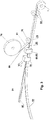
- a soft foam in the form of a wound first foam web 20 is provided on a first roll 10.
- the soft foam is provided on the first roll 10 in long lengths of up to 200 m, preferably between 5 and 100 m, more preferably between 10 and 60 m.
- All known open-cell, mixed-cell or closed-cell soft foams made of, for example, polyurethane, polyethylene, polyvinyl chloride or polypropylene, which reset after compression, can be used as foams.
- the first foam sheet 20 can be impregnated before further processing, but is preferably not yet impregnated.
- the foam web 20 can be transported and processed particularly well.
- the foam sheet 20 is usually located on the first roller 10 in a non-compressed or only slightly compressed state. It is also possible for the foam sheet 20 to be in a compressed state on the first roll 10, but after unwinding from the first roll 10, a timely resetting of the foam material in the process sequence must be ensured.
- the width of the foam sheet 20 is usually between 1 cm and 5 m, preferably between 1.0 m and 1.5 m.
- the height of the foam sheet 20 in the relaxed state is usually between 5 and 150 mm, more preferably between 10 and 80 mm.
- first foam webs 20 that are not wound on a first roll 10, but this requires a larger staging space.
- the first foam web 20 After unwinding from the first roll 10, the first foam web 20 is moved along a first conveying direction, which is indicated by the arrow V1. Subsequently, a film web 16 is applied to the top 21 of the first foam web 20 so as to form a laminated foam web 34.
- a film web 16 is applied to the top 21 of the first foam web 20 so as to form a laminated foam web 34.
- an adhesive tape web and / or a layer of an adhesive-like liquid medium can also be applied to the foam web 20.
- the film web 16 is provided on a film supply roll 26.
- the film web 16 and / or the adhesive tape web and / or the adhesive-like liquid medium is preferably applied from above to the top 21 of the foam web 20. This is usually done in the area of a first connection unit, which is represented schematically by the roller 28.
- the film web 16 or the adhesive tape web or the adhesive-like liquid medium should preferably adhere to the foam web, but not be laminated on or dried.
- the connecting step generally generally comprises a step of pressing the film web 16 or the adhesive tape web and the foam web 20 against one another.
- an adhesive-like liquid medium this is preferably applied to the foam web 20 by means of nozzles (eg melting nozzle, flat nozzle, mixing nozzle) or by roller application (transfer roller).
- the adhesive tape web is usually provided with at least one release film which is detached from the adhesive tape web before being applied to the foam web 20.
- the film web 16 can also itself comprise a layer of an adhesive tape or a layer of a hot melt adhesive. It is also possible to apply a spray adhesive to a film web 16.
- the film web 16 and / or the adhesive tape web and / or the adhesive-like liquid medium can also be attached to the underside 22 of the foam web 20 from below.
- Another exemplary embodiment provides for the application of film webs 16 and / or the adhesive tape webs and / or the adhesive-like liquid media on the top 21 and the bottom 22 of the foam web 20.
- At least one knife 38 By means of at least one knife 38, preferably a plurality of parallel knives 38, at least one through cut 40, preferably a plurality of parallel through cuts 40, is introduced into the laminated foam web 34 in the longitudinal direction of the laminated foam web 34, preferably parallel to the longitudinal edges 23 of the laminated foam web 34 ,
- the longitudinal edges 23 are the edges of the laminated foam web 34, which run parallel to the conveying direction V1 and orthogonal to the axial direction of the first roll 10.
- all other methods known to the person skilled in the art for cutting through foam sheets 20 can be used, such as, for example, cutting through saws, heated wires, laser cutting or water jet cutting.
- the continuous cuts 40 produce a plurality of first foam strips 50, which are provided with a film strip 24 and / or an adhesive tape strip and / or an adhesive-like liquid medium.
- the first foam strips 50 produced by the at least one cut 40 can have a different width, but they are preferably of the same width.
- the width of a foam strip 50 is between 5 mm and 30 cm, preferably between 1 and 12 cm.
- the first foam strips 50 can be wound onto a supply roll (not shown) at this point in order to move them for further processing and thus shorten the length of the entire production line, or they can be fed directly to further processing. All in all By using supply rolls as a buffer, the number of successive steps in a production line can be varied and thus the length of the individual sections of the production line can be adjusted according to the prevailing space conditions.
- the first foam sheet 20 is first cut into foam strips 50 and the individual foam strips 50 are then equipped with the film strips 24 and / or adhesive tape strips and / or the adhesive-like liquid medium.
- the film strips 24 and / or adhesive tape strips and / or the layer of the adhesive-like liquid medium can also only extend over part of a side surface of the foam strips 50.
- a film strip 24 can be arranged over several side surfaces.
- FIG. 2 An example of the optional process for producing second foam strips 60 is shown.
- a second foam sheet 58 made of soft foam is provided on a second roll 55, preferably uncompressed. After unwinding from the second roll 55, the second foam web 58 is moved along a second conveying direction V2. The same applies to the type of foam as to the foam of the first foam sheet 20.
- At least one knife 56 By means of at least one knife 56, preferably several parallel knives 56, at least one continuous cut 59, preferably several parallel continuous cuts 59, is made in the second foam web 58 in a direction parallel to the longitudinal edges of the foam web 58.
- the at least one continuous cut 59 thus produces a plurality of second foam strips 60.
- all other methods known to the person skilled in the art for severing foam webs can be used, for example severing by sawing, heated wires, laser cutting or water jet cutting.
- the second foam strips 60 can be wound up to form a supply roll (not shown) or can be fed directly to further processing.
- the second foam strips 60 can also be provided individually.
- the second foam strips 60 can have a film strip 24 on at least one side surface and / or an adhesive tape strip and / or an adhesive-like liquid medium.
- Fig. 3 shows essential steps of the first embodiment of the manufacturing method according to the invention, which is based on the steps Fig. 1 or 2 can connect.
- the first foam strips 50 provided with at least one film strip 24 and / or adhesive tape strips have already been pre-assembled, for example at another location or by another manufacturer, and only in this within the scope of the method according to the invention finished form can be used.
- a first foam strip 50 and a second foam strip 60 made of soft foam are brought together in such a way that a foam barrier layer web 70 is formed, in which a barrier layer 30 is arranged between the adjacent foam strips 50, 60.
- the foam strip 50 is preferably rotated 90 degrees about its longitudinal axis by means of a suitable deflection device, the longitudinal axis extending along a third conveying direction V3.
- a suitable deflection device e.g., the film strips 24 and / or the adhesive tape strips and / or the layer of the adhesive-like liquid medium is then located on a side surface of the foam strip 50 facing the foam strip 60.
- the first foam strip 50 and the second foam strip 60 become at the latest from the point of merging moved in the conveying direction V3.
- a plurality of first foam strips 50 can also be brought together with one or more second foam strips 60, or a plurality of second foam strips 60 with one or more first foam strips 50.
- the at least one first foam strip 50 can also be provided such that no rotation of the first foam strip 50 is necessary is.
- the at least one second foam strip 60 can be provided such that no rotation of the first foam strip 50 is necessary. It is always important that each side surface of the first foam strip 50 provided with a film strip 24 and / or an adhesive tape strip and / or an adhesive-like liquid medium faces the adjacent foam strip 50, 60.
- connection of the foam strips 50, 60 may require additional measures in addition to the merging of the foam strips 50, 60.
- a connection unit 36 can be provided, in which a step of applying heat and / or a step of pressing the foam strips 50, 60 together takes place.
- a possible embodiment of the connection unit 36 is described below with reference to FIG Fig. 5 described in more detail.
- a barrier layer 30 is formed from the film strip 24 and / or the adhesive tape strip and / or the adhesive-like liquid medium.
- the foam barrier layer web 70 can now be impregnated, for example, for a delayed reset.
- an impregnation unit 44 with subsequent drying unit 49 is suitable, as below with reference to FIG Fig. 6 described in more detail.
- the impregnation can also take place at other points in the manufacturing process or can be omitted.
- a common adhesive layer 80 is applied to all foam strips 50, 60 of the foam barrier layer sheet 70.
- the common adhesive layer 80 is applied to a surface of the foam barrier layer web 70 that runs perpendicular to the at least one barrier layer 30.
- the adhesive layer 80 is preferably provided on a supply roll 76 and is applied to the foam barrier layer web 70 in the area of an application station, shown schematically here by the roller 78, and is preferably pressed or rolled there.
- the use of double-sided adhesive tape as adhesive layer 80 is particularly suitable. This has the advantage that it is easy to apply to the foam barrier layer web 70 and thus at the same time provides an adhesive surface on the side facing away from the foam barrier layer web 70 by means of which the sealing tape 2 can be connected to a frame profile of a window during assembly. This second adhesive surface of the double-sided adhesive tape on the foam barrier layer web 70 opposite side is first laminated with a release film 81 to avoid sticking during further processing.
- the adhesive layer 80 can also contain textile fabrics or nonwoven layers.
- the common adhesive layer 80 After the common adhesive layer 80 has been applied to all foam strips 50, 60 of the foam barrier layer web 70, the latter is compressed and wound up to form a sealing tape roll 1.
- a sealing tape roll For example, one or more pairs of compression rollers 84 may be used for compression.
- a compression roller (not shown) can interact with the sealing tape roll directly when the sealing tape 2 is wound onto the sealing tape roll 1.
- two adhesive layers 80 can also be applied on opposite sides of the foam barrier layer web 70.
- a foam barrier layer web 70 comprising a plurality of foam strips 50, 60 and barrier layers 30 is compressed after the application of a common adhesive layer 80 to form a wide roll (not shown), which is then by means of at least one knife or at least one Saw to seal tape rolls 1 desired width can be cut, as below with reference to Fig. 7 is described in more detail.
- the conveying directions V1, V2 and V3 can be identical or different from one another.
- foam strips 12 can, like the production of the foam strips 60 in Fig. 2 respectively.
- the foam strips 12 can have a different width, but they are preferably of the same width.
- the width of a foam strip 12 is preferably between 5 and 150 mm, more preferably between 10 and 80 mm.
- each film strip 24 or adhesive tape strip is preferably provided on a spool 18 or roll and is preferably introduced into the intermediate space via suitable guide elements.
- Each spool 18 can be arranged in any position relative to the foam strips 12, with each film strip 24 or adhesive tape strip always being introduced into the corresponding intermediate space essentially in the conveying direction V1.
- Deflection elements for example deflection shoulders or deflection rollers, can also be used. It is also conceivable to provide a film web or adhesive tape web (preferably in the form of a roll) and cut it lengthways into individual film strips 24 or adhesive tape strips before these are introduced into the spaces between the foam strips 12.
- Adhesive tape strips are usually provided with at least one peel-off film which is detached from the adhesive tape strip before being inserted into the space.
- each spool 18 in such a way that the film strip 24 or adhesive tape strip can be introduced into the corresponding intermediate space without being deflected.
- the connecting step generally comprises generally a step of applying heat and / or a step of pressing the foam strips 12 together.
- the connection to the foam strips 12 in the connecting unit 36 is preferably carried out by lamination.
- the film strip 24 can itself comprise one or more strips of adhesive tape or a solid layer of hot melt adhesive.
- an adhesive-like liquid medium is introduced into the spaces between the foam strips 12 by means of nozzles (for example melting nozzle, flat nozzle, mixing nozzle) or by roller application (transfer roller).
- nozzles for example melting nozzle, flat nozzle, mixing nozzle
- roller application transfer roller
- a connection of the foam strips 12 can then take place, preferably in the connecting unit 36, the adhesive generally being solidified.
- the connection of the foam strips 12 will usually again comprise a step of applying heat and / or a step of pressing the foam strips 12 together. It is also possible to according to a film strip 24 Fig. 4 to apply a spray adhesive.
- a foam barrier layer web 70 is produced, which has at least one barrier layer 30, which can be attributed to the film strip 24, the adhesive tape strip and / or the adhesive-like liquid medium.
- the connecting unit 36 preferably comprises a pair of pressure rollers 41, which are arranged on both narrow sides of the foam barrier layer web 70 and press the individual foam strips 12 against one another.
- the pressure rollers 41 are preferably each rotatably mounted about a vertical axis, the direction of rotation of the two pressure rollers 41 being in opposite directions.
- a pair of pull rollers 42 are also disposed in the connection unit 36, which extend across the width of the foam barrier layer web 70 and receive the foam barrier layer web 70 in a nip.
- the two pulling rollers 42 are each driven in opposite directions about a horizontal axis and thus pull the foam barrier layer web 70 through the connecting unit 36.
- Such pairs of pulling rollers 42 can also be used at other points in the manufacturing process.
- the pull rollers 42 can also be arranged upstream of the pressure rollers 41 in the connecting unit 36.
- the connection unit 36 preferably also comprises a heating device 43 which is shown in FIG Fig. 5 is only hinted at.
- the heater 43 may preferably include a housing that surrounds the foam barrier sheet 70.
- the heating device 43 can be designed for all possible types of heating.
- the heater 43 can be used in combination with the pressure rollers 41. It is also possible, only to provide the heating device 43 or only the pressure rollers 41 in the connecting unit 36.
- the heating device 43 can also be designed to firmly connect only the upper and lower edge regions of the foam barrier layer web 70 to one another by adjusting the temperature and / or duration of the heating accordingly.
- each barrier layer 30 is preferably to reduce or prevent the passage of air and / or water vapor. This also applies to all other exemplary embodiments.
- the foam barrier layer web 70 can be wound onto a supply roll. However, it is also possible to continuously feed the foam barrier layer web 70 to the further processing steps. As a result, the number of successive steps in a production line can be varied and thus the length of the individual sections of the production line can be adjusted according to the prevailing space conditions.
- the intermediate roller 57 can already be made at this point Fig. 7 or even directly the end product, the sealing tape roll 1.
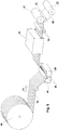
- the foam barrier layer web 70 previously wound on a supply roll 40 is first unwound again.
- the foam barrier layer web 70 is passed through an impregnation unit 44 in a next step along a second conveying direction V2, which may be identical or different to V1 depending on the arrangement of the sections of the production line.
- Two rollers 45 guide the foam barrier layer web 70 into a bath of a suitable impregnate 48 and the foam soaks up with the impregnate.
- Usual impregnates and methods for impregnating foams are known to the person skilled in the art.
- the foam barrier layer web 70 is preferably compressed between the rollers 45 in order to promote the absorption of the impregnate 48 by the subsequent resetting of the foam.
- the impregnated foam barrier layer web 70 is dried in a drying unit 49.
- the impregnated unit is in this Foam barrier layer web 70 is dried in a known manner, for example by a heating fan or radiant heater.
- the foam barrier layer web 70 is then rolled up to an intermediate roller 57, preferably using compression rollers 51, 52. It may be sufficient if only one compression roller 51 is used directly at the transition to the intermediate roller 57, or a pair of compression rollers 52 may be used beforehand to compress the foam barrier sheet 70. In the example shown, both options are used in combination.
- the foam barrier layer web 70 is present on the intermediate roller 57 in the highly compressed state.
- the drying unit 49 after the impregnation unit 44 can also function as a heating device for firmly connecting all elements of the foam barrier layer web 70 if no heating device 43 has been used previously. In this way, a heating process could be omitted. This also applies to the embodiment of FIG Fig. 3 ,
- an adhesive layer 80 for example a double-sided adhesive tape laminated on one side with a release film, is preferably applied to the foam barrier layer web 70.
- the adhesive layer 80 is in turn mounted on a supply roll 76 or supply spool and is pulled off this.
- the adhesive layer 80 is preferably applied to the foam barrier layer web 70 simultaneously with the winding of the foam barrier layer web 70 to the intermediate roller 57, the compression roller 51 generating the pressure for connecting the adhesive layer 80 and the foam barrier layer web 70.
- the foam can also be impregnated at other positions in the production process.
- the impregnation of the foam can be dispensed with completely or can have been done before the foam strips 12 are provided.
- the impregnation of the foam takes place after the introduction of each film strip 24 or adhesive tape strip into the space between two adjacent foam strips 12, since each film strip 24 or adhesive tape strip adheres better to a non-impregnated foam and is therefore easier to connect to it.
- the intermediate roller 57 is severed according to the variant of the second exemplary embodiment of the method according to the invention at one or more points in the axial direction in order to produce a plurality of sealing tape rollers 1 that are less wide than the intermediate roller 57.
- the intermediate roller is preferably severed 57 carried out by means of one or more parallel saws 72. In Fig. 7 only one saw 72 is shown, and a further parallel section for severing the intermediate roller 57 is indicated by dashed lines.
- Other suitable methods of cutting can also be used here (for example knives, heated wires, laser cutting, water jet cutting).
- the intermediate roller 57 is cut into sealing tape rolls 1 such that foam strips 12 and the at least one barrier layer 30 alternate in the axial direction of the sealing tape roll 1.
- Each radially extending barrier layer 30 is received in a sealing tape roll 1 between two foam strips 12, as a result of which the sealing tape 2 has an increased seal against drafts and / or vapor diffusion, and each barrier layer 30 is simultaneously protected against external damage.
- the double-sided adhesive layer 80 which is preferably present and is laminated with a release film is not shown here.
- sealing tape rolls 1 are produced with exactly one barrier layer 30. Sealing tape rolls 1 with a plurality of inner barrier layers 30 can also be produced. In this case, the barrier layers 30 of a sealing tape 2 can have different vapor diffusion tightness. Likewise, for the formation of the barrier layers 30, foil strips 24 (or adhesive materials) can be used, the vapor diffusion tightness of which adapts variably to the ambient conditions.
- the step of cutting the intermediate roll 57 into individual sealing tape rolls 1 can also be omitted if the entire intermediate roll 57 is already used as a sealing tape roll 1. In this case, it may also be useful to nevertheless separate the edge regions of the intermediate roller 57 in the sense of a smoother outer surface of the sealing tape roll 1. Otherwise, the sealing tape roll 1 is manufactured, for example, as in FIG Fig. 3 shown.
- Fig. 8 shows a further alternative possibility of the final processing of the foam barrier layer web 70 for the production of sealing tape rolls 1.
- the variant shown on the right can also use a or several knives 66 or saws in the area of at least one foam strip 12 are severed in the longitudinal direction.
- at least one cut 68 is inserted into the foam barrier layer web 70, as a result of which at least two foam barrier layer strips 69 are produced.
- Each foam barrier layer strip 69 can then be wound up into a finished sealing tape roll 1.
- a double-sided adhesive layer 80 provided with a release film is preferably applied as in FIG Fig. 6 (in Fig. 8 not shown). In this way the in Fig. 7 illustrated step of dividing an intermediate roller 57 is omitted.
- Compression rollers 52 can preferably also be used here for pre-compression of the individual foam barrier layer strips 69.
- the two in 1 to 3 or 4 to 7 described variants differ only in the production of the foam barrier layer web 70. Subsequently, all further processing steps can be carried out identically. With both exemplary embodiments, wider intermediate rolls 57 can be produced, which are then divided into individual sealing tape rolls 1 (see Fig. 7 ). Likewise, narrow sealing tape rolls 1 can be produced directly with both exemplary embodiments, without a wide intermediate roll 57 being produced (see Fig. 3 ). Even the variant Fig. 8 is possible with both embodiments.
- all foam webs, foam strips, foam barrier layer webs or foam barrier layer strips are preferably moved forward by rolling, particularly preferably by pairs of rollers moving in opposite directions. Treadmills can also be used. Such means of transportation can also be used for the film strips, film webs, adhesive tape strips or adhesive tape webs.
- the heating devices mentioned in the exemplary embodiments are usually designed as warm air blowers.
- radiation heating can also be used, for example by means of infrared heating or microwave heating.
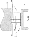
- Fig. 9 shows an installation situation of the sealing tape 2 unwound from a sealing tape roll 1 according to the invention.
- the sealing tape 2 For installation, the sealing tape 2 must first be unwound from the sealing tape roll 1 and cut into strips of any length. Usually the Length of the sealing tape strips adapted to the outer contours of a window frame or a door frame to be sealed.
- the sealing tape 2 is then preferably attached to the window frame 112 or door frame by means of the adhesive layer 80 or by means of other adhesive layers, adhesive tapes or other suitable means.
- the sealing tape 2 is received between a window frame 112 and a masonry 110 in order to seal the joint between them.
- the illustrated sealing tape 2 in this case comprises a first foam strip 50, which is provided with a barrier layer 30, and a second foam strip 60.
- the barrier layer 30 is received in a protective manner between the foam strips 50, 60, causing damage during storage, transport and the Assembly of the sealing tape roll 1 or the sealing tape 2 can be avoided.
- the sealing tape 2 is to be installed in such a way that at least one barrier layer 30 runs from the window frame 112 to the masonry 110 and thus essentially orthogonally to a functional direction F of the sealing tape 2.
- the functional direction F extends parallel to the surfaces of the window frame 112 and the masonry 110 forming the joint to be sealed from an outside of the room (in Fig. 9 left) to an inside of the room (in Fig. 9 right). In this way, a reliable seal against drafts and vapor diffusion can be guaranteed.
- the first foam strip 50 can consist of a different foam material than the second foam strip 60.
- the first foam strips 50 and the second foam strips 60 can be impregnated with different impregnate or only the first foam strips 50 or only that second foam strip 60 may be impregnated.
- the first foam strips 50 can have a different color than the second foam strips 60. In this way, for example, the preferred installation direction of the sealing tape 2 can be identified.
- any number of barrier layers 30 in the sealing tape 2 is possible.
- different widths and / or heights of the first foam strips 50 and / or different widths and / or heights of the second foam strips 60 are also conceivable, even within the same sealing tape 2.
- the first foam strip (s) 50 can also have a different width and / or or have height than the second foam strip or strips 60.
- the width of the sealing tape 2 is usually between 5 mm and 20 cm, preferably between 1 cm and 12 cm. In the relaxed state, the sealing tape 2 generally has a height of between 5 mm and 30 cm, preferably between 1 and 12 cm.
- FIG. 9 The exemplary embodiment shown forms exactly one first foam strip 50 together with exactly one second foam strip 60 the foam barrier layer web 70, which is wound up to form the sealing tape roll 1.
- the foam barrier layer web 70 which is wound up to form the sealing tape roll 1.
- first foam strips 50 here three first foam strips 50, brought together with exactly one second foam strip 60 to form the foam barrier layer web 70, with exactly one barrier layer 30 being applied to each first foam strip 50 and the second foam strip 60 being attached an edge of the foam barrier sheet 70 is disposed.
- the barrier layers 30 are arranged between adjacent foam strips 50, 60.
- two barrier layers of two adjacent foam strips 50, 50 or 50, 60 can be arranged directly next to one another.
- foam barrier layer sheets 70 of any type can be designed in this way, foam strips 50, 60 and barrier layers 30 preferably alternating in the direction of function F and one foam strip 50, 60 being arranged at one edge of the foam barrier layer sheet 70.
- the sealing tape 2 shown comprises three barrier layers 30 between four foam strips 82, the two outer foam strips 82 being only half as wide as the two inner foam layers 82.
- Variants of the sealing tape 2 shown can be produced with both variants of the manufacturing method according to claim 1 and claim 6.
- the reference numerals 50, 60 in Fig. 9 and 10 also stand for reference number 12. All of the aforementioned variants of the foam strips 50, 60 are also suitable for the foam strips 12, in particular different foam strips 12 in the same sealing tape can have different properties.
- a “barrier layer” 30 refers to a layer that is suitable for reducing the passage of air or the vapor diffusion through the sealing tape 2. A complete block against the passage of air or against vapor diffusion is possible, but not absolutely necessary. It may be expedient if at least one barrier layer 30 is moisture-variable in such a way that it is more diffusion-proof at high air humidity than at lower air humidity or vice versa.
- the materials that can be used for the barrier layer 30 for example DE 10 2010 055 788 A1 or on EP 2 733 271 A1 referenced, the content of which is to be included in this application.
- each barrier layer 30 is permanently elastic, so that it remains permanently elastic even after storage of the sealing tape roll 1 in the compressed state when the sealing tape 2 is reset and in the installed state of the sealing tape 2 in a joint always lies close to the joint flanks.
Landscapes
- Engineering & Computer Science (AREA)
- Civil Engineering (AREA)
- Structural Engineering (AREA)
- Architecture (AREA)
- General Engineering & Computer Science (AREA)
- Physics & Mathematics (AREA)
- Electromagnetism (AREA)
- Mechanical Engineering (AREA)
- Lining Or Joining Of Plastics Or The Like (AREA)
- Adhesive Tapes (AREA)
- Laminated Bodies (AREA)
Priority Applications (4)
| Application Number | Priority Date | Filing Date | Title |
|---|---|---|---|
| EP14182235.3A EP2990553B1 (de) | 2014-08-26 | 2014-08-26 | Verfahren zur herstellung einer dichtbandrolle |
| PL14182235T PL2990553T3 (pl) | 2014-08-26 | 2014-08-26 | Sposób wytwarzania rolki taśmy uszczelniającej |
| DK14182235.3T DK2990553T3 (da) | 2014-08-26 | 2014-08-26 | Fremgangsmåde til fremstilling af en tætningsbåndrulle |
| US14/826,258 US9938109B2 (en) | 2014-08-26 | 2015-08-14 | Method for the production of a sealing tape roll |
Applications Claiming Priority (1)
| Application Number | Priority Date | Filing Date | Title |
|---|---|---|---|
| EP14182235.3A EP2990553B1 (de) | 2014-08-26 | 2014-08-26 | Verfahren zur herstellung einer dichtbandrolle |
Publications (2)
| Publication Number | Publication Date |
|---|---|
| EP2990553A1 EP2990553A1 (de) | 2016-03-02 |
| EP2990553B1 true EP2990553B1 (de) | 2020-01-22 |
Family
ID=51392149
Family Applications (1)
| Application Number | Title | Priority Date | Filing Date |
|---|---|---|---|
| EP14182235.3A Active EP2990553B1 (de) | 2014-08-26 | 2014-08-26 | Verfahren zur herstellung einer dichtbandrolle |
Country Status (4)
| Country | Link |
|---|---|
| US (1) | US9938109B2 (pl) |
| EP (1) | EP2990553B1 (pl) |
| DK (1) | DK2990553T3 (pl) |
| PL (1) | PL2990553T3 (pl) |
Families Citing this family (15)
| Publication number | Priority date | Publication date | Assignee | Title |
|---|---|---|---|---|
| US20140087198A1 (en) * | 2012-09-26 | 2014-03-27 | Web Industries, Inc. | Prepreg tape slitting method and apparatus |
| DE102016114227A1 (de) * | 2016-08-01 | 2018-02-01 | Tremco Illbruck Produktion Gmbh | Verfahren und Vorrichtung zum Herstellen eines Dichtbandes |
| DE102017105323A1 (de) | 2017-03-14 | 2018-09-20 | Tremco Illbruck Produktion Gmbh | Dichtband und Verfahren zum Herstellen eines Dichtbandes |
| DE102017110856A1 (de) | 2017-05-18 | 2018-12-06 | tremco illbruck GmbH | Herstellungsverfahren für Dichtband und Dichtband |
| PL3453806T5 (pl) | 2017-09-01 | 2024-01-29 | Iso-Chemie Gmbh | Element uszczelniający |
| CN109229559B (zh) * | 2018-07-04 | 2024-03-08 | 吴付利 | 双层卷膜的放置及转动装置 |
| DE102018118854A1 (de) | 2018-08-02 | 2020-02-06 | tremco illbruck GmbH | Herstellungsverfahren für Dichtband und Dichtband |
| EP3757306A1 (de) | 2018-11-07 | 2020-12-30 | ISO-Chemie GmbH | Dichtband |
| EP3680304B1 (de) * | 2019-01-11 | 2024-08-07 | Tremco CPG Germany GmbH | Verfahren und vorrichtung zur herstellung eines dichtbandes und dichtband |
| DE102020100140A1 (de) * | 2020-01-07 | 2021-07-08 | Tremco CPG Germany GmbH | Verfahren und Vorrichtung zur Herstellung eines Dichtbandes und Dichtband |
| DE102019100686B4 (de) | 2019-01-11 | 2022-03-10 | Tremco CPG Germany GmbH | Verfahren und Vorrichtung zur Herstellung eines Dichtbandes |
| CN110697467B (zh) * | 2019-11-01 | 2021-08-03 | 潍坊驼王实业有限公司 | 一种多层土工布复合成型的收卷装置 |
| WO2022043217A1 (de) | 2020-08-24 | 2022-03-03 | Hilti Aktiengesellschaft | Dichtprofil und trockenbauwand |
| DE102022129553A1 (de) * | 2022-11-09 | 2024-05-16 | Tremco CPG Germany GmbH | Fugendichtband und Verfahren zu dessen Herstellung |
| EP4575114A1 (de) | 2023-12-22 | 2025-06-25 | Hanno-Werk GmbH & Co. KG | Fugendichtungsband |
Citations (15)
| Publication number | Priority date | Publication date | Assignee | Title |
|---|---|---|---|---|
| DE1635590A1 (de) | 1965-05-17 | 1971-04-22 | Du Pont | Verfahren zur Herstellung von Faserflaechenmaterialien |
| DE2410121A1 (de) | 1974-03-02 | 1975-09-18 | Irbit Holding Ag | Verfahren zum aufwickeln von platten, streifen oder dergleichen aus elastisch komprimierbarem material |
| DE1784467C3 (de) | 1967-08-17 | 1976-05-20 | N.V. Asphalt-Bitumen-Onderneming Asbiton, Zwijndrecht (Niederlande) | Vorkomprimiertes Fugendichtungsband, Verfahren zu seiner Herstellung und Transporteinheit aus solchen Bändern |
| FR2309768A1 (fr) * | 1975-04-28 | 1976-11-26 | Mora Alcide | Produit elastique de jointoiement en matiere cellulaire, en particulier pour joints de dilatation et similaires |
| EP0072955A1 (de) | 1981-08-22 | 1983-03-02 | Irbit Holding AG | Zu einer Rolle aufgewickelter Schaumstoff-Streifen, vorzugsweise zu Abdichtungszwecken |
| US4486990A (en) * | 1982-04-21 | 1984-12-11 | Bauch Tamil D | Removable window insulation system |
| DE4020230A1 (de) | 1989-06-30 | 1991-01-03 | Heribert Hiendl | Fugendichtungsband |
| DE19641415A1 (de) | 1996-10-08 | 1998-04-16 | Hanno Werk Gmbh & Co Kg | Dichtungsband und Verfahren zur Herstellung des Dichtungsbandes |
| DE202005000873U1 (de) | 2005-01-20 | 2005-03-24 | Wirz Peter | Dichtband zum Abdichten einer Fuge zwischen einem in eine Laibung eines Gebäudes eingesetzten Rahmen und der Laibung |
| DE102004047193A1 (de) | 2004-01-31 | 2005-09-22 | Deutsche Rockwool Mineralwoll Gmbh + Co Ohg | Verfahren zur Herstellung einer Dämmstoffbahn aus Mineralfasern sowie Dämmstoffbahn |
| US20090246498A1 (en) * | 2008-03-31 | 2009-10-01 | Iso-Chemie Gmbh | Sealing Strip of Soft Foam |
| DE102010055788A1 (de) | 2010-12-23 | 2012-06-28 | Hanno-Werk Gmbh & Co. Kg | Fugendichtungsband |
| EP2620565A1 (de) | 2012-01-24 | 2013-07-31 | ISO-Chemie GmbH | Dichtband zum Abdichten einer Fuge |
| DE202012005049U1 (de) | 2012-05-23 | 2013-08-26 | Tremco Illbruck Produktion Gmbh | Dichtband |
| DE202012101990U1 (de) | 2012-05-23 | 2013-08-27 | Tremco Illbruck Produktion Gmbh | Dichtband |
Family Cites Families (8)
| Publication number | Priority date | Publication date | Assignee | Title |
|---|---|---|---|---|
| US4238082A (en) * | 1979-08-14 | 1980-12-09 | Lund Morten A | Method and apparatus for slitting and rewinding web materials |
| US4342432A (en) * | 1981-01-30 | 1982-08-03 | Lund Arnold M | Control system for slitter-rewinder apparatus |
| US4572452A (en) * | 1984-11-21 | 1986-02-25 | Illinois Carbon Products | Apparatus for slitting and winding tape |
| DE3544277C1 (de) * | 1985-12-14 | 1987-04-02 | Irbit Res & Consulting Ag | Dichtungsstreifen |
| US4740256A (en) * | 1986-08-14 | 1988-04-26 | Minnesota Mining And Manufacturing Company | Method of making a weather strip |
| CA2141924C (en) * | 1994-03-02 | 2003-08-19 | Michael J. Sinn | Method of making pressure sensitive adhesive tape rolls with a transparent to the core appearance |
| EP1936246B2 (de) | 2006-12-18 | 2013-04-03 | ISO-Chemie GmbH | Dichtband aus Weichschaum und Verfahren zu seiner Herstellung |
| DE202012104454U1 (de) | 2012-11-19 | 2014-02-25 | Tremco Illbruck Produktion Gmbh | Zwangsbelüftetes Gebäude mit Wandaufbau umfassend Dichtungsband |
-
2014
- 2014-08-26 PL PL14182235T patent/PL2990553T3/pl unknown
- 2014-08-26 EP EP14182235.3A patent/EP2990553B1/de active Active
- 2014-08-26 DK DK14182235.3T patent/DK2990553T3/da active
-
2015
- 2015-08-14 US US14/826,258 patent/US9938109B2/en active Active
Patent Citations (16)
| Publication number | Priority date | Publication date | Assignee | Title |
|---|---|---|---|---|
| DE1635590A1 (de) | 1965-05-17 | 1971-04-22 | Du Pont | Verfahren zur Herstellung von Faserflaechenmaterialien |
| DE1784467C3 (de) | 1967-08-17 | 1976-05-20 | N.V. Asphalt-Bitumen-Onderneming Asbiton, Zwijndrecht (Niederlande) | Vorkomprimiertes Fugendichtungsband, Verfahren zu seiner Herstellung und Transporteinheit aus solchen Bändern |
| DE2410121A1 (de) | 1974-03-02 | 1975-09-18 | Irbit Holding Ag | Verfahren zum aufwickeln von platten, streifen oder dergleichen aus elastisch komprimierbarem material |
| FR2309768A1 (fr) * | 1975-04-28 | 1976-11-26 | Mora Alcide | Produit elastique de jointoiement en matiere cellulaire, en particulier pour joints de dilatation et similaires |
| EP0072955A1 (de) | 1981-08-22 | 1983-03-02 | Irbit Holding AG | Zu einer Rolle aufgewickelter Schaumstoff-Streifen, vorzugsweise zu Abdichtungszwecken |
| US4486990A (en) * | 1982-04-21 | 1984-12-11 | Bauch Tamil D | Removable window insulation system |
| DE4020230A1 (de) | 1989-06-30 | 1991-01-03 | Heribert Hiendl | Fugendichtungsband |
| DE19641415A1 (de) | 1996-10-08 | 1998-04-16 | Hanno Werk Gmbh & Co Kg | Dichtungsband und Verfahren zur Herstellung des Dichtungsbandes |
| DE102004047193A1 (de) | 2004-01-31 | 2005-09-22 | Deutsche Rockwool Mineralwoll Gmbh + Co Ohg | Verfahren zur Herstellung einer Dämmstoffbahn aus Mineralfasern sowie Dämmstoffbahn |
| DE202005000873U1 (de) | 2005-01-20 | 2005-03-24 | Wirz Peter | Dichtband zum Abdichten einer Fuge zwischen einem in eine Laibung eines Gebäudes eingesetzten Rahmen und der Laibung |
| US20090246498A1 (en) * | 2008-03-31 | 2009-10-01 | Iso-Chemie Gmbh | Sealing Strip of Soft Foam |
| DE102010055788A1 (de) | 2010-12-23 | 2012-06-28 | Hanno-Werk Gmbh & Co. Kg | Fugendichtungsband |
| US20130154201A1 (en) * | 2010-12-23 | 2013-06-20 | Hanno-Werk Gmbh & Co. Kg | Joint-sealing strip |
| EP2620565A1 (de) | 2012-01-24 | 2013-07-31 | ISO-Chemie GmbH | Dichtband zum Abdichten einer Fuge |
| DE202012005049U1 (de) | 2012-05-23 | 2013-08-26 | Tremco Illbruck Produktion Gmbh | Dichtband |
| DE202012101990U1 (de) | 2012-05-23 | 2013-08-27 | Tremco Illbruck Produktion Gmbh | Dichtband |
Also Published As
| Publication number | Publication date |
|---|---|
| EP2990553A1 (de) | 2016-03-02 |
| PL2990553T3 (pl) | 2020-06-29 |
| DK2990553T3 (da) | 2020-03-30 |
| US9938109B2 (en) | 2018-04-10 |
| US20160060068A1 (en) | 2016-03-03 |
Similar Documents
| Publication | Publication Date | Title |
|---|---|---|
| EP2990553B1 (de) | Verfahren zur herstellung einer dichtbandrolle | |
| EP2990551B1 (de) | Verfahren zur Herstellung einer Dichtbandrolle | |
| EP2990575B1 (de) | Dichtband zum abdichten einer fuge | |
| EP2990552B1 (de) | Verfahren zur herstellung einer dichtbandrolle und dichtbandrolle | |
| EP2620565A1 (de) | Dichtband zum Abdichten einer Fuge | |
| EP3278967A1 (de) | Verfahren und vorrichtung zum herstellen eines dichtbandes und abdichtband mit einem grundträger | |
| EP3628808B1 (de) | Verfahren zur herstellung eines schaumstoffdichtbandes und schaumstoffdichtband | |
| DE4126912A1 (de) | Vorrichtung zum herstellen einer materialbahn | |
| EP2744865B1 (de) | Verfahren zur herstellung eines klebebandes | |
| EP3453806B2 (de) | Dichtelement | |
| EP3567177B1 (de) | Verfahren zur herstellung von dichtbandrollen | |
| EP0176918B1 (de) | Verfahren zum Bearbeiten und Aufbringen einer Schutzfolie auf eine Platte | |
| EP3404156B1 (de) | Herstellungsverfahren für dichtband | |
| EP3608482B1 (de) | Verfahren zum herstellen einer dichtbandrolle | |
| EP3650608B1 (de) | Verfahren zum herstellen einer dichtbandrolle | |
| DE3206164A1 (de) | Verfahren und vorrichtung zur herstellung von mehrschicht-platten | |
| EP3603941B1 (de) | Herstellungsverfahren für dichtband und dichtband | |
| DE102019100686B4 (de) | Verfahren und Vorrichtung zur Herstellung eines Dichtbandes | |
| DE2124139C3 (de) | Verfahren zur Herstellung von Schichtstoffen und Vorrichtung zur Durchführung des Verfahrens | |
| DE4114125A1 (de) | Kunststoffschaumrandstreifen | |
| CH620487A5 (en) | Process and device for producing hollow building blocks | |
| EP2565357A2 (de) | Verfahren und Vorrichtung zur Bearbeitung eines Kunststoffbandes bei der Herstellung eines rahmenförmigen Abstandhalters für Isolierglasscheiben | |
| DE3611628C2 (pl) | ||
| AT527968A2 (de) | Verfahren und Vorrichtung zur Bearbeitung von Hartschaumplatten und daraus hergestellte Plattenstapel | |
| DE2163930B2 (de) | Verfahren und einrichtung zum kontinuierlichen herstellen von mit verschlussrippen versehenen, fuer die beutelherstellung geeigneten folien |
Legal Events
| Date | Code | Title | Description |
|---|---|---|---|
| PUAI | Public reference made under article 153(3) epc to a published international application that has entered the european phase |
Free format text: ORIGINAL CODE: 0009012 |
|
| AK | Designated contracting states |
Kind code of ref document: A1 Designated state(s): AL AT BE BG CH CY CZ DE DK EE ES FI FR GB GR HR HU IE IS IT LI LT LU LV MC MK MT NL NO PL PT RO RS SE SI SK SM TR |
|
| AX | Request for extension of the european patent |
Extension state: BA ME |
|
| 17P | Request for examination filed |
Effective date: 20160830 |
|
| RBV | Designated contracting states (corrected) |
Designated state(s): AL AT BE BG CH CY CZ DE DK EE ES FI FR GB GR HR HU IE IS IT LI LT LU LV MC MK MT NL NO PL PT RO RS SE SI SK SM TR |
|
| STAA | Information on the status of an ep patent application or granted ep patent |
Free format text: STATUS: EXAMINATION IS IN PROGRESS |
|
| 17Q | First examination report despatched |
Effective date: 20181213 |
|
| GRAP | Despatch of communication of intention to grant a patent |
Free format text: ORIGINAL CODE: EPIDOSNIGR1 |
|
| STAA | Information on the status of an ep patent application or granted ep patent |
Free format text: STATUS: GRANT OF PATENT IS INTENDED |
|
| INTG | Intention to grant announced |
Effective date: 20190930 |
|
| GRAS | Grant fee paid |
Free format text: ORIGINAL CODE: EPIDOSNIGR3 |
|
| GRAJ | Information related to disapproval of communication of intention to grant by the applicant or resumption of examination proceedings by the epo deleted |
Free format text: ORIGINAL CODE: EPIDOSDIGR1 |
|
| GRAL | Information related to payment of fee for publishing/printing deleted |
Free format text: ORIGINAL CODE: EPIDOSDIGR3 |
|
| STAA | Information on the status of an ep patent application or granted ep patent |
Free format text: STATUS: EXAMINATION IS IN PROGRESS |
|
| GRAR | Information related to intention to grant a patent recorded |
Free format text: ORIGINAL CODE: EPIDOSNIGR71 |
|
| STAA | Information on the status of an ep patent application or granted ep patent |
Free format text: STATUS: GRANT OF PATENT IS INTENDED |
|
| GRAA | (expected) grant |
Free format text: ORIGINAL CODE: 0009210 |
|
| STAA | Information on the status of an ep patent application or granted ep patent |
Free format text: STATUS: THE PATENT HAS BEEN GRANTED |
|
| INTC | Intention to grant announced (deleted) | ||
| INTG | Intention to grant announced |
Effective date: 20191212 |
|
| AK | Designated contracting states |
Kind code of ref document: B1 Designated state(s): AL AT BE BG CH CY CZ DE DK EE ES FI FR GB GR HR HU IE IS IT LI LT LU LV MC MK MT NL NO PL PT RO RS SE SI SK SM TR |
|
| REG | Reference to a national code |
Ref country code: GB Ref legal event code: FG4D Free format text: NOT ENGLISH |
|
| REG | Reference to a national code |
Ref country code: CH Ref legal event code: EP |
|
| REG | Reference to a national code |
Ref country code: AT Ref legal event code: REF Ref document number: 1226984 Country of ref document: AT Kind code of ref document: T Effective date: 20200215 |
|
| REG | Reference to a national code |
Ref country code: IE Ref legal event code: FG4D Free format text: LANGUAGE OF EP DOCUMENT: GERMAN |
|
| REG | Reference to a national code |
Ref country code: DE Ref legal event code: R096 Ref document number: 502014013513 Country of ref document: DE |
|
| REG | Reference to a national code |
Ref country code: NL Ref legal event code: FP |
|
| REG | Reference to a national code |
Ref country code: DK Ref legal event code: T3 Effective date: 20200327 |
|
| REG | Reference to a national code |
Ref country code: LT Ref legal event code: MG4D |
|
| PG25 | Lapsed in a contracting state [announced via postgrant information from national office to epo] |
Ref country code: FI Free format text: LAPSE BECAUSE OF FAILURE TO SUBMIT A TRANSLATION OF THE DESCRIPTION OR TO PAY THE FEE WITHIN THE PRESCRIBED TIME-LIMIT Effective date: 20200122 Ref country code: PT Free format text: LAPSE BECAUSE OF FAILURE TO SUBMIT A TRANSLATION OF THE DESCRIPTION OR TO PAY THE FEE WITHIN THE PRESCRIBED TIME-LIMIT Effective date: 20200614 Ref country code: RS Free format text: LAPSE BECAUSE OF FAILURE TO SUBMIT A TRANSLATION OF THE DESCRIPTION OR TO PAY THE FEE WITHIN THE PRESCRIBED TIME-LIMIT Effective date: 20200122 Ref country code: NO Free format text: LAPSE BECAUSE OF FAILURE TO SUBMIT A TRANSLATION OF THE DESCRIPTION OR TO PAY THE FEE WITHIN THE PRESCRIBED TIME-LIMIT Effective date: 20200422 |
|
| PG25 | Lapsed in a contracting state [announced via postgrant information from national office to epo] |
Ref country code: BG Free format text: LAPSE BECAUSE OF FAILURE TO SUBMIT A TRANSLATION OF THE DESCRIPTION OR TO PAY THE FEE WITHIN THE PRESCRIBED TIME-LIMIT Effective date: 20200422 Ref country code: SE Free format text: LAPSE BECAUSE OF FAILURE TO SUBMIT A TRANSLATION OF THE DESCRIPTION OR TO PAY THE FEE WITHIN THE PRESCRIBED TIME-LIMIT Effective date: 20200122 Ref country code: LV Free format text: LAPSE BECAUSE OF FAILURE TO SUBMIT A TRANSLATION OF THE DESCRIPTION OR TO PAY THE FEE WITHIN THE PRESCRIBED TIME-LIMIT Effective date: 20200122 Ref country code: HR Free format text: LAPSE BECAUSE OF FAILURE TO SUBMIT A TRANSLATION OF THE DESCRIPTION OR TO PAY THE FEE WITHIN THE PRESCRIBED TIME-LIMIT Effective date: 20200122 Ref country code: IS Free format text: LAPSE BECAUSE OF FAILURE TO SUBMIT A TRANSLATION OF THE DESCRIPTION OR TO PAY THE FEE WITHIN THE PRESCRIBED TIME-LIMIT Effective date: 20200522 |
|
| REG | Reference to a national code |
Ref country code: DE Ref legal event code: R026 Ref document number: 502014013513 Country of ref document: DE |
|
| PG25 | Lapsed in a contracting state [announced via postgrant information from national office to epo] |
Ref country code: SM Free format text: LAPSE BECAUSE OF FAILURE TO SUBMIT A TRANSLATION OF THE DESCRIPTION OR TO PAY THE FEE WITHIN THE PRESCRIBED TIME-LIMIT Effective date: 20200122 Ref country code: SK Free format text: LAPSE BECAUSE OF FAILURE TO SUBMIT A TRANSLATION OF THE DESCRIPTION OR TO PAY THE FEE WITHIN THE PRESCRIBED TIME-LIMIT Effective date: 20200122 Ref country code: RO Free format text: LAPSE BECAUSE OF FAILURE TO SUBMIT A TRANSLATION OF THE DESCRIPTION OR TO PAY THE FEE WITHIN THE PRESCRIBED TIME-LIMIT Effective date: 20200122 Ref country code: CZ Free format text: LAPSE BECAUSE OF FAILURE TO SUBMIT A TRANSLATION OF THE DESCRIPTION OR TO PAY THE FEE WITHIN THE PRESCRIBED TIME-LIMIT Effective date: 20200122 Ref country code: EE Free format text: LAPSE BECAUSE OF FAILURE TO SUBMIT A TRANSLATION OF THE DESCRIPTION OR TO PAY THE FEE WITHIN THE PRESCRIBED TIME-LIMIT Effective date: 20200122 Ref country code: LT Free format text: LAPSE BECAUSE OF FAILURE TO SUBMIT A TRANSLATION OF THE DESCRIPTION OR TO PAY THE FEE WITHIN THE PRESCRIBED TIME-LIMIT Effective date: 20200122 Ref country code: ES Free format text: LAPSE BECAUSE OF FAILURE TO SUBMIT A TRANSLATION OF THE DESCRIPTION OR TO PAY THE FEE WITHIN THE PRESCRIBED TIME-LIMIT Effective date: 20200122 |
|
| PLBI | Opposition filed |
Free format text: ORIGINAL CODE: 0009260 |
|
| PLAX | Notice of opposition and request to file observation + time limit sent |
Free format text: ORIGINAL CODE: EPIDOSNOBS2 |
|
| 26 | Opposition filed |
Opponent name: TREMCO CPG GERMANY GMBH Effective date: 20201022 |
|
| PG25 | Lapsed in a contracting state [announced via postgrant information from national office to epo] |
Ref country code: SI Free format text: LAPSE BECAUSE OF FAILURE TO SUBMIT A TRANSLATION OF THE DESCRIPTION OR TO PAY THE FEE WITHIN THE PRESCRIBED TIME-LIMIT Effective date: 20200122 |
|
| PLBB | Reply of patent proprietor to notice(s) of opposition received |
Free format text: ORIGINAL CODE: EPIDOSNOBS3 |
|
| PG25 | Lapsed in a contracting state [announced via postgrant information from national office to epo] |
Ref country code: MC Free format text: LAPSE BECAUSE OF FAILURE TO SUBMIT A TRANSLATION OF THE DESCRIPTION OR TO PAY THE FEE WITHIN THE PRESCRIBED TIME-LIMIT Effective date: 20200122 |
|
| PG25 | Lapsed in a contracting state [announced via postgrant information from national office to epo] |
Ref country code: LU Free format text: LAPSE BECAUSE OF NON-PAYMENT OF DUE FEES Effective date: 20200826 |
|
| REG | Reference to a national code |
Ref country code: DE Ref legal event code: R082 Ref document number: 502014013513 Country of ref document: DE Representative=s name: KROHER STROBEL RECHTS- UND PATENTANWAELTE PART, DE |
|
| PG25 | Lapsed in a contracting state [announced via postgrant information from national office to epo] |
Ref country code: IE Free format text: LAPSE BECAUSE OF NON-PAYMENT OF DUE FEES Effective date: 20200826 |
|
| PLCK | Communication despatched that opposition was rejected |
Free format text: ORIGINAL CODE: EPIDOSNREJ1 |
|
| PG25 | Lapsed in a contracting state [announced via postgrant information from national office to epo] |
Ref country code: TR Free format text: LAPSE BECAUSE OF FAILURE TO SUBMIT A TRANSLATION OF THE DESCRIPTION OR TO PAY THE FEE WITHIN THE PRESCRIBED TIME-LIMIT Effective date: 20200122 Ref country code: MT Free format text: LAPSE BECAUSE OF FAILURE TO SUBMIT A TRANSLATION OF THE DESCRIPTION OR TO PAY THE FEE WITHIN THE PRESCRIBED TIME-LIMIT Effective date: 20200122 Ref country code: CY Free format text: LAPSE BECAUSE OF FAILURE TO SUBMIT A TRANSLATION OF THE DESCRIPTION OR TO PAY THE FEE WITHIN THE PRESCRIBED TIME-LIMIT Effective date: 20200122 |
|
| APBM | Appeal reference recorded |
Free format text: ORIGINAL CODE: EPIDOSNREFNO |
|
| APBP | Date of receipt of notice of appeal recorded |
Free format text: ORIGINAL CODE: EPIDOSNNOA2O |
|
| APAH | Appeal reference modified |
Free format text: ORIGINAL CODE: EPIDOSCREFNO |
|
| PG25 | Lapsed in a contracting state [announced via postgrant information from national office to epo] |
Ref country code: MK Free format text: LAPSE BECAUSE OF FAILURE TO SUBMIT A TRANSLATION OF THE DESCRIPTION OR TO PAY THE FEE WITHIN THE PRESCRIBED TIME-LIMIT Effective date: 20200122 Ref country code: AL Free format text: LAPSE BECAUSE OF FAILURE TO SUBMIT A TRANSLATION OF THE DESCRIPTION OR TO PAY THE FEE WITHIN THE PRESCRIBED TIME-LIMIT Effective date: 20200122 |
|
| PG25 | Lapsed in a contracting state [announced via postgrant information from national office to epo] |
Ref country code: GR Free format text: LAPSE BECAUSE OF FAILURE TO SUBMIT A TRANSLATION OF THE DESCRIPTION OR TO PAY THE FEE WITHIN THE PRESCRIBED TIME-LIMIT Effective date: 20200122 |
|
| APBQ | Date of receipt of statement of grounds of appeal recorded |
Free format text: ORIGINAL CODE: EPIDOSNNOA3O |
|
| P01 | Opt-out of the competence of the unified patent court (upc) registered |
Effective date: 20230427 |
|
| REG | Reference to a national code |
Ref country code: DE Ref legal event code: R100 Ref document number: 502014013513 Country of ref document: DE |
|
| APBU | Appeal procedure closed |
Free format text: ORIGINAL CODE: EPIDOSNNOA9O |
|
| PLBN | Opposition rejected |
Free format text: ORIGINAL CODE: 0009273 |
|
| STAA | Information on the status of an ep patent application or granted ep patent |
Free format text: STATUS: OPPOSITION REJECTED |
|
| 27O | Opposition rejected |
Effective date: 20240613 |
|
| PGFP | Annual fee paid to national office [announced via postgrant information from national office to epo] |
Ref country code: NL Payment date: 20250826 Year of fee payment: 12 |
|
| PGFP | Annual fee paid to national office [announced via postgrant information from national office to epo] |
Ref country code: DE Payment date: 20250826 Year of fee payment: 12 Ref country code: DK Payment date: 20250822 Year of fee payment: 12 |
|
| PGFP | Annual fee paid to national office [announced via postgrant information from national office to epo] |
Ref country code: PL Payment date: 20250724 Year of fee payment: 12 Ref country code: IT Payment date: 20250827 Year of fee payment: 12 |
|
| PGFP | Annual fee paid to national office [announced via postgrant information from national office to epo] |
Ref country code: BE Payment date: 20250822 Year of fee payment: 12 Ref country code: GB Payment date: 20250827 Year of fee payment: 12 |
|
| PGFP | Annual fee paid to national office [announced via postgrant information from national office to epo] |
Ref country code: FR Payment date: 20250826 Year of fee payment: 12 Ref country code: AT Payment date: 20250822 Year of fee payment: 12 |
|
| PGFP | Annual fee paid to national office [announced via postgrant information from national office to epo] |
Ref country code: CH Payment date: 20250901 Year of fee payment: 12 |