EP2989350B1 - Circuit hydraulique destiné aux transmissions de véhicules industriels et agricoles - Google Patents
Circuit hydraulique destiné aux transmissions de véhicules industriels et agricoles Download PDFInfo
- Publication number
- EP2989350B1 EP2989350B1 EP14720096.8A EP14720096A EP2989350B1 EP 2989350 B1 EP2989350 B1 EP 2989350B1 EP 14720096 A EP14720096 A EP 14720096A EP 2989350 B1 EP2989350 B1 EP 2989350B1
- Authority
- EP
- European Patent Office
- Prior art keywords
- pressure
- section
- regulating
- hydraulic circuit
- vehicle
- Prior art date
- Legal status (The legal status is an assumption and is not a legal conclusion. Google has not performed a legal analysis and makes no representation as to the accuracy of the status listed.)
- Active
Links
- 230000005540 biological transmission Effects 0.000 title claims description 36
- 230000001105 regulatory effect Effects 0.000 claims description 43
- 239000012530 fluid Substances 0.000 claims description 36
- 238000002485 combustion reaction Methods 0.000 claims description 20
- 238000005461 lubrication Methods 0.000 claims description 8
- 238000011144 upstream manufacturing Methods 0.000 claims description 4
- 230000001050 lubricating effect Effects 0.000 description 5
- 238000009412 basement excavation Methods 0.000 description 4
- 238000010276 construction Methods 0.000 description 1
- 230000001276 controlling effect Effects 0.000 description 1
- 230000000694 effects Effects 0.000 description 1
- 238000000034 method Methods 0.000 description 1
Images


Classifications
-
- F—MECHANICAL ENGINEERING; LIGHTING; HEATING; WEAPONS; BLASTING
- F16—ENGINEERING ELEMENTS AND UNITS; GENERAL MEASURES FOR PRODUCING AND MAINTAINING EFFECTIVE FUNCTIONING OF MACHINES OR INSTALLATIONS; THERMAL INSULATION IN GENERAL
- F16H—GEARING
- F16H57/00—General details of gearing
- F16H57/04—Features relating to lubrication or cooling or heating
- F16H57/0434—Features relating to lubrication or cooling or heating relating to lubrication supply, e.g. pumps ; Pressure control
- F16H57/0446—Features relating to lubrication or cooling or heating relating to lubrication supply, e.g. pumps ; Pressure control the supply forming part of the transmission control unit, e.g. for automatic transmissions
-
- F—MECHANICAL ENGINEERING; LIGHTING; HEATING; WEAPONS; BLASTING
- F15—FLUID-PRESSURE ACTUATORS; HYDRAULICS OR PNEUMATICS IN GENERAL
- F15B—SYSTEMS ACTING BY MEANS OF FLUIDS IN GENERAL; FLUID-PRESSURE ACTUATORS, e.g. SERVOMOTORS; DETAILS OF FLUID-PRESSURE SYSTEMS, NOT OTHERWISE PROVIDED FOR
- F15B13/00—Details of servomotor systems ; Valves for servomotor systems
- F15B13/02—Fluid distribution or supply devices characterised by their adaptation to the control of servomotors
-
- F—MECHANICAL ENGINEERING; LIGHTING; HEATING; WEAPONS; BLASTING
- F15—FLUID-PRESSURE ACTUATORS; HYDRAULICS OR PNEUMATICS IN GENERAL
- F15B—SYSTEMS ACTING BY MEANS OF FLUIDS IN GENERAL; FLUID-PRESSURE ACTUATORS, e.g. SERVOMOTORS; DETAILS OF FLUID-PRESSURE SYSTEMS, NOT OTHERWISE PROVIDED FOR
- F15B15/00—Fluid-actuated devices for displacing a member from one position to another; Gearing associated therewith
- F15B15/08—Characterised by the construction of the motor unit
-
- F—MECHANICAL ENGINEERING; LIGHTING; HEATING; WEAPONS; BLASTING
- F16—ENGINEERING ELEMENTS AND UNITS; GENERAL MEASURES FOR PRODUCING AND MAINTAINING EFFECTIVE FUNCTIONING OF MACHINES OR INSTALLATIONS; THERMAL INSULATION IN GENERAL
- F16H—GEARING
- F16H57/00—General details of gearing
- F16H57/04—Features relating to lubrication or cooling or heating
- F16H57/0434—Features relating to lubrication or cooling or heating relating to lubrication supply, e.g. pumps ; Pressure control
- F16H57/0435—Pressure control for supplying lubricant; Circuits or valves therefor
-
- F—MECHANICAL ENGINEERING; LIGHTING; HEATING; WEAPONS; BLASTING
- F16—ENGINEERING ELEMENTS AND UNITS; GENERAL MEASURES FOR PRODUCING AND MAINTAINING EFFECTIVE FUNCTIONING OF MACHINES OR INSTALLATIONS; THERMAL INSULATION IN GENERAL
- F16H—GEARING
- F16H61/00—Control functions within control units of change-speed- or reversing-gearings for conveying rotary motion ; Control of exclusively fluid gearing, friction gearing, gearings with endless flexible members or other particular types of gearing
- F16H61/0021—Generation or control of line pressure
- F16H61/0025—Supply of control fluid; Pumps therefore
-
- F—MECHANICAL ENGINEERING; LIGHTING; HEATING; WEAPONS; BLASTING
- F15—FLUID-PRESSURE ACTUATORS; HYDRAULICS OR PNEUMATICS IN GENERAL
- F15B—SYSTEMS ACTING BY MEANS OF FLUIDS IN GENERAL; FLUID-PRESSURE ACTUATORS, e.g. SERVOMOTORS; DETAILS OF FLUID-PRESSURE SYSTEMS, NOT OTHERWISE PROVIDED FOR
- F15B2211/00—Circuits for servomotor systems
- F15B2211/50—Pressure control
- F15B2211/505—Pressure control characterised by the type of pressure control means
- F15B2211/50509—Pressure control characterised by the type of pressure control means the pressure control means controlling a pressure upstream of the pressure control means
- F15B2211/50536—Pressure control characterised by the type of pressure control means the pressure control means controlling a pressure upstream of the pressure control means using unloading valves controlling the supply pressure by diverting fluid to the return line
-
- F—MECHANICAL ENGINEERING; LIGHTING; HEATING; WEAPONS; BLASTING
- F15—FLUID-PRESSURE ACTUATORS; HYDRAULICS OR PNEUMATICS IN GENERAL
- F15B—SYSTEMS ACTING BY MEANS OF FLUIDS IN GENERAL; FLUID-PRESSURE ACTUATORS, e.g. SERVOMOTORS; DETAILS OF FLUID-PRESSURE SYSTEMS, NOT OTHERWISE PROVIDED FOR
- F15B2211/00—Circuits for servomotor systems
- F15B2211/50—Pressure control
- F15B2211/555—Pressure control for assuring a minimum pressure, e.g. by using a back pressure valve
-
- F—MECHANICAL ENGINEERING; LIGHTING; HEATING; WEAPONS; BLASTING
- F15—FLUID-PRESSURE ACTUATORS; HYDRAULICS OR PNEUMATICS IN GENERAL
- F15B—SYSTEMS ACTING BY MEANS OF FLUIDS IN GENERAL; FLUID-PRESSURE ACTUATORS, e.g. SERVOMOTORS; DETAILS OF FLUID-PRESSURE SYSTEMS, NOT OTHERWISE PROVIDED FOR
- F15B2211/00—Circuits for servomotor systems
- F15B2211/50—Pressure control
- F15B2211/56—Control of an upstream pressure
-
- F—MECHANICAL ENGINEERING; LIGHTING; HEATING; WEAPONS; BLASTING
- F15—FLUID-PRESSURE ACTUATORS; HYDRAULICS OR PNEUMATICS IN GENERAL
- F15B—SYSTEMS ACTING BY MEANS OF FLUIDS IN GENERAL; FLUID-PRESSURE ACTUATORS, e.g. SERVOMOTORS; DETAILS OF FLUID-PRESSURE SYSTEMS, NOT OTHERWISE PROVIDED FOR
- F15B2211/00—Circuits for servomotor systems
- F15B2211/50—Pressure control
- F15B2211/565—Control of a downstream pressure
-
- F—MECHANICAL ENGINEERING; LIGHTING; HEATING; WEAPONS; BLASTING
- F15—FLUID-PRESSURE ACTUATORS; HYDRAULICS OR PNEUMATICS IN GENERAL
- F15B—SYSTEMS ACTING BY MEANS OF FLUIDS IN GENERAL; FLUID-PRESSURE ACTUATORS, e.g. SERVOMOTORS; DETAILS OF FLUID-PRESSURE SYSTEMS, NOT OTHERWISE PROVIDED FOR
- F15B2211/00—Circuits for servomotor systems
- F15B2211/80—Other types of control related to particular problems or conditions
- F15B2211/88—Control measures for saving energy
-
- F—MECHANICAL ENGINEERING; LIGHTING; HEATING; WEAPONS; BLASTING
- F16—ENGINEERING ELEMENTS AND UNITS; GENERAL MEASURES FOR PRODUCING AND MAINTAINING EFFECTIVE FUNCTIONING OF MACHINES OR INSTALLATIONS; THERMAL INSULATION IN GENERAL
- F16H—GEARING
- F16H61/00—Control functions within control units of change-speed- or reversing-gearings for conveying rotary motion ; Control of exclusively fluid gearing, friction gearing, gearings with endless flexible members or other particular types of gearing
- F16H61/0021—Generation or control of line pressure
- F16H2061/0037—Generation or control of line pressure characterised by controlled fluid supply to lubrication circuits of the gearing
Definitions
- This invention relates to a hydraulic circuit for the transmissions of industrial and agricultural vehicles of the type comprising an internal combustion engine connected to a transmission provided with a feed pump for the hydraulic circuit and an output shaft driven by the internal combustion engine which is capable of providing useful power to drive other working components.
- US 2004/211174 A discloses a hydraulic circuit for the transmission of a work vehicle.
- US 2005/143224 A discloses a hydraulic controller for a hydraulic actuator incorporated in a power transmission.
- earthmoving machines such as for example backhoe loaders and excavators, but in general many vehicles for industrial and agricultural use, use a transmission to provide the motive power required to move them.
- the hydraulic circuits used in these transmissions typically comprise a pump to raise the oil to the working pressure and deliver it to a lubrication circuit and the vehicle transmission components.
- the pump is driven by an internal combustion engine which is caused to work at variable speeds and powers depending upon the pressure/power required to move the vehicle.
- the oil pressure in the hydraulic circuit is however maintained above a lower limit value because a certain throughput is required in order to lubricate the transmission even when the vehicle is stopped.
- a so-called power take-off that is to say an output shaft, also known as a PTO shaft, coupled to the internal combustion engine, which drives the vehicle's auxiliary pump and which is used to transmit power from the internal combustion engine to the moving arm of the excavator, in the case of an earthmoving machine, or in general to other working components.
- the power take-off is connected to the pump of another hydraulic circuit which brings about movement of the arm and other tools.
- two different working situations for the vehicle can be envisaged - a first situation in which the vehicle is moving and power may be requested for the vehicle's hydraulic system, a second situation in which the power to the vehicle's hydraulic circuit is provided when it is stopped.
- both the power provided to the working components and the pressure provided to the transmission depend on the rotation speed of the internal combustion engine and therefore in known vehicles it is not possible to provide high power to the working components and limit the pressure to the hydraulic circuit of the transmission to the minimum values necessary to ensure adequate lubrication at the same time.
- the transmission is not required to operate when it is engaged purely in excavation work with the vehicle stopped.
- This invention has a number of significant advantages.
- the main advantage lies in the fact that it can reduce the energy wastage which takes place during the stage when an earthmoving machine is purely excavating and in general when industrial vehicles are only engaged in working.
- the hydraulic circuit according to this invention is simple from the point of view of construction and has a minimum effect on the overall cost of the vehicle.
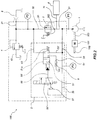
- a hydraulic circuit for the transmissions of industrial and agricultural vehicles is indicated as a whole by reference number 100.
- this hydraulic circuit is intended to be used in vehicles of the type comprising an internal combustion engine 101 connected to the hydraulic circuit and an output shaft 102 driven by the internal combustion engine forming a power take-off (PTO) to provide working power to working components of the vehicle, which are not shown in the figure.
- PTO power take-off
- These working components may be represented by a moving arm on which excavation means are supported or by other working means or services which receive power from output shaft 102.
- Hydraulic circuit 100 comprises a feed pump 1 which operates on a working fluid for the circuit, typically oil, in order to raise it to a main working pressure p1.
- a working fluid for the circuit typically oil
- Feed pump 1 is driven by internal combustion engine 101 and is in particular connected, for example by means of a key, to a transmission shaft 103 of a transmission unit, which is not shown in the figure, which is in turn connected to engine 101.
- a change in the rotation speed of the engine will result in a change in the power transmitted to both pump 1 and the working components via the power take-off.
- the circuit may also comprise an inlet filter 11 and a delivery filter 12, illustrated in Figure 6 , upstream and downstream from pump 1 respectively.
- the working fluid leaving pump 1 is intended to provide operative fluid at pressure p1 to a hydraulically operated auxiliary unit 6, such as the arm of a backhoe, via an auxiliary uses section 36, to provide the lubrication necessary for the transmission components via a delivery section 21 which delivers fluid to a heat exchanger 7 and a lubricating circuit 8, and which may also be intended for a torque converter 2, which is only illustrated in connection to the embodiment of Figures 5 to 7 , as well as the heat exchanger 7 and the lubricating circuit 8. More in general, the a delivery section 21 is connected to a hydraulic transmission proving power to wheels or tracks of the vehicle for moving it.
- the throughput of working fluid delivered to the lubrication circuit and, if present, to torque converter 2 may have a preset pressure, indicated below as the secondary working pressure p2, and as a consequence the pressure between the output of the pump and the input to the torque converter must be regulated.
- the circuit according to this invention comprises a main pressure regulator 3 in correspondence of which a first change in pressure ⁇ p1 in the working fluid occurs.
- the working fluid delivered by pump 1 to regulator 3 through an inlet section 31 at a main working pressure p1 is delivered by regulator 3 to lubricating circuit 8 and/or the torque converter through an outlet section 32 at the working pressure of converter p2 which is lower than pressure p1.
- main pressure regulator 3 which is illustrated diagrammatically in the figure, comprises a valve body 30 within which there is housed a moving plug which moves in an axial direction depending upon the pressure of the working fluid, opposed by a resilient member 302.
- pressure p1 will be regulated by resilient member 302.
- the working fluid operated by the pump 1 is also delivered at a working pressure to the hydraulically operated auxiliary unit 6 via an auxiliary uses section 36 which is positioned upstream the main pressure regulator 3 and, in the present embodiment, connected to the inlet section 31.
- the delivery section 21 is positioned downstream the main pressure regulator 3.
- Circuit 100 further comprises a second pressure regulator 4 connected to outlet section 32 in order to regulate the pressure p2 fed to torque converter 2 and/or lubrication circuit 8.
- This second pressure regulator 4 preferably has characteristics similar to main pressure regulator 3 and is connected to a discharge branch 42 in such a way as to regulate pressure p2 on the basis of a corresponding resilient member 402.
- the change in pressure ⁇ p1 between pressure p1 and pressure p2 is therefore defined on the basis of the pressure regulation brought about by resilient members 302 and 402.
- the circuit according to this invention makes it possible to regulate the pressure change ⁇ p1 between sections 31 and 32.
- regulation of pressure change ⁇ p1 takes place by bypassing main pressure regulator 3.
- a flow of working fluid is intercepted by means of a regulating or by-pass section 33 which transmits the working fluid originating from pump 1 to a switching device 5 through a connecting branch 33a.
- switching device 5 takes the form of a switching valve 50 and comprises a moving slide 51, movement of which in a corresponding valve body switches operation of the valve between a first and a second operating condition. Movement of slide 51 is brought about by a suitable operating unit 56 which in this embodiment takes the form of a solenoid system of the ON/OFF type.
- pressure p1 is regulated by means of main pressure regulator 3 and in particular by the calibration of resilient member 302, while pressure p2 is regulated through second pressure regulator 4 through the calibration of corresponding resilient member 402.
- valve 50 is also connected to a second regulating section 43 connected to an outlet section 32 and a third regulating section 93, which is connected to a pressure limiting valve 9, constructed in such a way as to open when fed by a flow of fluid which respectively meets a preset pressure p9 which is less than the main regulating pressure of regulator 3.
- Limiting valve 9 is also constructed in such a way that once open after the aforesaid pressure has been exceeded it will discharge fluid through a further discharge section.
- regulating sections 33, 43 and 93 are in communication via slide 51.
- connecting branch 33a will make it possible to reduce the pressure difference between p1 and p2, in this case making it substantially equal to zero, and as a consequence it will be possible to maintain a sufficiently high pressure p2 for lubricating circuit 8 with a low working pressure for pump 1.
- the power P at which pump 1 operates can advantageously be regulated independently of the rotation speed of the engine, and therefore of the throughput delivered by the pump.
- This regulation will however be independent of the regulation of pressure p2 in such a way that it is possible to maintain the minimum pressure required to lubricate the transmission even when the vehicle is stopped.
- Regulation of pressure difference ⁇ p1 is in fact associated with the value of pressure p3 in regulating section 33, which varies according to the position of valve 50.
- the drive unit comprises a three-way and two-position operating valve 56' activated by a solenoid.
- Operating valve 56' may selectively deliver a flow of working fluid taken from inlet section 31 towards slide 51 of switching valve 50 in such a way as to make use of the hydraulic circuit itself to move slide 51 and achieve the open operating condition.
- the flow of operating fluid is delivered to operating valve 56 through a feed section 35 connected to regulating section 33 which is closed in the closed operating position.
- Switching valve 50 and operating valve 56 are shown in the first operating condition in Figures 3A and 3B and in the second operating condition in Figures 4A and 4B .
- FIG. 5 this illustrates a further embodiment of the hydraulic circuit for the transmissions of industrial and agricultural vehicles 100 according to this invention.
- main pressure regulator 3' comprises a valve body 30 within which there is housed a moving plug 301 which moves in an axial direction according to the pressure of the operating fluid, opposed by a resilient member 302.
- valve body 30 also comprises an outlet opening 303 which is open when the pressure acting on plug 301 reaches a predetermined level.
- an overflow channel 304 which makes it possible also to provide a flow of fluid to the opposite face of the plug with respect to that on which the main pressure acts. This flow of fluid will give rise to a pressure p3 which opposes movement of plug 301 together with resilient member 302 and therefore the pressure at which the outlet opening will open, and consequently the pressure at which fluid will flow out from regulator 3' will also be determined by pressure p4 which is therefore referred to as the first regulating pressure.
- pressure p1 will be equal to the sum of the pressure determined by resilient member 302 and regulating pressure p3.
- circuit 100 in order to regulate pressure p2, circuit 100 according to this embodiment will comprise a maximum pressure regulator 4'.
- Maximum pressure regulator 4' has characteristics similar to pressure regulator 3' and therefore also comprises a valve body 40 in which a moving plug can move in an axial direction in order to open an outlet opening 403. Again in this case movement of the plug is opposed by a resilient member 402 and a second regulating pressure p4 of an overflow flow provided by a channel 404.
- regulator 4' the plug will be operated through a pressure p2 via a section 41 of the hydraulic circuit connected to the outlet section 32 of regulator 3', while outlet opening 403 is connected to a discharge section 42, preferably at constant pressure.
- pressure p2 will be defined as the sum of the pressure determined by resilient member 402 and regulating pressure p4.
- switching device 5' is advantageously able to regulate regulating pressures p3 and p4.
- Switching device 5' is connected by means of corresponding regulating sections 33', 43' to pressure regulators 3 and 4, and they comprise pilot valves 53, 54.
- Pilot valves 53 and 54 are such that they open when they are provided with a flow of fluid which meets pressures p3 and p4 respectively and once open discharges fluid through a further discharge section 55.
- Regulating sections 33' and 43' are also connected to a switching valve 50', preferably of the solenoid On/Off type, with characteristics similar to the valve previously described.
- this valve 50' closes off connecting branches 33' and 43' from regulating sections 33' and 43' through the action of moving slide 51 in such a way that the flow of working fluid which is drawn off in pressure regulators 3' and 4' is wholly delivered to the pilot valves.
- moving slide 51 is arranged in such a way that it allows working fluid to pass into branches 33a' and 43a' as far as a discharge section 56 in such a way that regulating pressures p3 and p4 are equal to the discharge pressure, neglecting load losses, specifically equal to ambient pressure.
- pressures p1 and p2 will be defined by the opposing action of resilient members 302 and 402.
- the power P at which pump 1 operates may advantageously be regulated independently of the rotation speed of the engine, and therefore the flow delivered by the pump.
- This regulation will however be independent of the regulation of pressure p2, in such a way that it is possible to maintain the minimum pressure required for lubricating the transmission even when the vehicle is stopped.
- circuit uses particularly economical components and will not give rise to high costs in comparison with known circuits.
Landscapes
- Engineering & Computer Science (AREA)
- General Engineering & Computer Science (AREA)
- Mechanical Engineering (AREA)
- Physics & Mathematics (AREA)
- Fluid Mechanics (AREA)
- Control Of Fluid Gearings (AREA)
- Control Of Transmission Device (AREA)
- Harvester Elements (AREA)
- Motor Power Transmission Devices (AREA)
Claims (8)
- Circuit hydraulique (100) pour les transmissions de véhicules industriels et agricoles du type comprenant un moteur à combustion interne (101), une transmission hydraulique (2, 7, 8) raccordée au circuit hydraulique (100), une unité auxiliaire opérée hydrauliquement (6) et un arbre de sortie (102) entrainé par le moteur à combustion interne (101) pouvant fournir une puissance suffisante pour entrainer d'autres composants de travail, ledit circuit comprenant :a. une pompe d'alimentation (1) fonctionnant sur un fluide de travail du circuit hydraulique et pouvant être raccordée au moteur à combustion interne (101) du véhicule pour être entraînée ;b. une section de distribution (21) pouvant être raccordée à une transmission hydraulique (2, 7, 8) du véhicule, ladite transmission comprenant un circuit de lubrification (8) et/ou un convertisseur de couple (2) du véhicule ;c. une section d'utilisations auxiliaire (36) pouvant être raccordée à l'unité auxiliaire opérée hydrauliquement (6) pour fournir le fluide de travail à une pression de travail dans l'unité auxiliaire opérée hydrauliquement (6) ;d. un régulateur de pression principale (3 ; 3') pouvant conduire à une première variation de pression (Δp1) d'un fluide de commande dans le circuit à travers une section d'entrée (31) raccordée à la pompe (1) et une section de sortie (32) raccordée à la section de distribution (21) ;e. une première section de régulation (33 ; 33') raccordant ledit régulateur de pression principale (3 ; 3') à un dispositif de commutation (5 ; 5') et à laquelle une première pression de régulation (p3) est associée, ledit dispositif de commutation (5 ; 5') pouvant ouvrir ou fermer alternativement une tubulure de raccord (33a ; 33a') à ladite section de régulation (33 ; 33') afin de modifier la première pression de régulation (p3) et réguler une première variation de pression (Δp1) ;f. un régulateur de pression maximale (4 ; 4') raccordé à la section de distribution (21) pouvant conduire à une deuxième variation de pression (Δp2) du fluide de commande entre la section de sortie (32) et la section de distribution (42) ;dans lequel ladite section d'utilisations auxiliaire (36) et ladite section de distribution (21) sont positionnées respectivement en amont et en aval dudit régulateur de pression principale (3 ; 3'), dans lequel ledit dispositif de commutation (5) comprend une soupape de commutation (50) pouvant sélectivement fermer la section de régulation (33) et la placer en raccord respectif avec une deuxième section de régulation (43) raccordée à ladite section de sortie (32) et à une troisième section de régulation (93) raccordée à une soupape de limitation de pression (9).
- Circuit hydraulique selon la revendication 1, dans lequel les moyens de commutation (5) comprennent une glissière mobile (51), la tubulure de raccord (33a) étant fermée en étant interceptée par la glissière mobile (51), cette glissière mobile (51) étant déplacée par un flux du fluide de commande.
- Circuit hydraulique (100) pour les transmissions de véhicules industriels et agricoles du type comprenant un moteur à combustion interne (101), une transmission hydraulique (2, 7, 8) raccordée au circuit hydraulique (100), une unité auxiliaire opérée hydrauliquement (6) et un arbre de sortie (102) entrainé par le moteur à combustion interne (101) pouvant fournir une puissance suffisante pour entrainer d'autres composants de travail, ledit circuit comprenant :a. une pompe d'alimentation (1) fonctionnant sur un fluide de travail du circuit hydraulique et pouvant être raccordée au moteur à combustion interne (101) du véhicule afin d'être entraînée ;b. une section de distribution (21) pouvant être raccordée à une transmission hydraulique (2, 7, 8) du véhicule, ladite transmission comprenant un circuit de lubrification (8) et/ou un convertisseur de couple (2) du véhicule ;c. une section d'utilisations auxiliaire (36) pouvant être raccordée à l'unité auxiliaire opérée hydrauliquement (6) pour fournir le fluide de travail à une pression de travail dans l'unité auxiliaire opérée hydrauliquement (6) ;d. un régulateur de pression principale (3 ; 3') pouvant conduire à une première variation de pression (Δp1) d'un fluide de commande dans le circuit à travers une section d'entrée (31) raccordée à la pompe (1) et une section de sortie (32) raccordée à la section de distribution (21) ;e. une première section de régulation (33') raccordant ledit régulateur de pression principale (3 ; 3') à un dispositif de commutation (5 ; 5') et à laquelle une première pression de régulation (p3) est associée, ledit dispositif de commutation (5 ; 5') pouvant ouvrir ou fermer alternativement une tubulure de raccord (33a ; 33a') à ladite section de régulation (33') afin de modifier la première pression de régulation (p3) et réguler une première variation de pression (Δp1) ;f. un régulateur de pression maximale (4 ; 4') raccordé à la section de distribution (21) pouvant conduire à une deuxième variation de pression (Δp2) du fluide de commande entre la section de sortie (32) et la section de distribution (42) ;dans lequel ladite section d'utilisations auxiliaire (36) et ladite section de distribution (21) sont positionnées respectivement en amont et en aval dudit régulateur de pression principale (3 ; 3'), dans lequel la deuxième variation de pression (Δp2) peut être régulée en fonction d'une deuxième pression de régulation (p4) fournie à travers une deuxième section de régulation de pression (43'), le dispositif de commutation (5') comprenant des soupapes pilotes (53, 54) respectivement raccordées aux première et deuxième sections de régulation (33', 43') et une soupape de commutation (50') pouvant être commutée entres les positions de fonctionnement, une première position dans laquelle le fluide de commande dans les première et deuxième sections de régulation (33', 43') circule entièrement jusqu'aux soupapes pilotes (53, 54) et une deuxième position dans laquelle au moins une partie du flux de fluide de commande circule jusqu'à une section de déversement (55).
- Circuit hydraulique selon la revendication 3, dans lequel les régulateurs de pression (3', 4') comprennent un corps de soupape (30, 40), un organe de fermeture mobile (301, 401), un organe résilient (302, 402) et un canal de purge (304, 404) à travers lequel une fraction du flux de fluide de commande est passé aux sections de régulation (33', 43').
- Circuit hydraulique selon la revendication 4, dans lequel une pression de travail principale (p1) à laquelle la pompe (1) fonctionne agit sur un côté de l'organe de fermeture mobile (301) du régulateur de pression principale (3') et une pression de fonctionnement maximale (p2) agit sur une face de l'organe de fermeture mobile (401) du régulateur de pression maximale (4').
- Circuit hydraulique selon la revendication 5, dans lequel la pression de fonctionnement principale (p1) est soumise à la résistance de l'organe résilient (302) du régulateur de pression principale (3') et à la première pression de régulation (p3), et la pression de fonctionnement maximale (p2) est soumise à la résistance de l'organe résilient (402) du régulateur de pression maximale (4') et à la deuxième pression de régulation (p4).
- Circuit hydraulique selon l'une quelconque des revendications précédentes, comprenant en outre un convertisseur de couple (2) raccordé à la section de sortie (32).
- Véhicule agricole ou industriel comprenant :a. un moteur à combustion interne (101) ;b. un arbre de sortie (102) entraîné par ledit moteur à combustion interne (101) et pouvant fournir une puissance utile pour entrainer d'autres composants de travail ; etc. une transmission hydraulique (2, 7, 8) pour déplacer le véhicule,d. une unité auxiliaire à commande hydraulique (6) ;caractérisé en ce que ledit véhicule comprend en outre un circuit hydraulique (100) selon l'une des revendications précédentes, dans lequel ladite pompe d'alimentation (1) est entraînée par ledit moteur à combustion interne (101), ladite transmission hydraulique (2, 7, 8) étant raccordée à ladite section de distribution (21) et ladite unité auxiliaire opéré hydrauliquement (6) étant raccordée à ladite section d'utilisations auxiliaire (36).
Priority Applications (1)
| Application Number | Priority Date | Filing Date | Title |
|---|---|---|---|
| PL14720096T PL2989350T3 (pl) | 2013-04-24 | 2014-04-24 | Obwód hydrauliczny do przekładni pojazdów przemysłowych i rolniczych |
Applications Claiming Priority (2)
| Application Number | Priority Date | Filing Date | Title |
|---|---|---|---|
| IT000112A ITPD20130112A1 (it) | 2013-04-24 | 2013-04-24 | Circuito idraulico per trasmissioni di veicoli industriali ed agricoli |
| PCT/EP2014/058404 WO2014174050A1 (fr) | 2013-04-24 | 2014-04-24 | Circuit hydraulique destiné aux transmissions de véhicules industriels et agricoles |
Publications (2)
| Publication Number | Publication Date |
|---|---|
| EP2989350A1 EP2989350A1 (fr) | 2016-03-02 |
| EP2989350B1 true EP2989350B1 (fr) | 2018-01-31 |
Family
ID=48672686
Family Applications (1)
| Application Number | Title | Priority Date | Filing Date |
|---|---|---|---|
| EP14720096.8A Active EP2989350B1 (fr) | 2013-04-24 | 2014-04-24 | Circuit hydraulique destiné aux transmissions de véhicules industriels et agricoles |
Country Status (9)
| Country | Link |
|---|---|
| US (1) | US9835243B2 (fr) |
| EP (1) | EP2989350B1 (fr) |
| CN (1) | CN105378346B (fr) |
| BR (1) | BR112015027029A2 (fr) |
| ES (1) | ES2667422T3 (fr) |
| HU (1) | HUE037522T2 (fr) |
| IT (1) | ITPD20130112A1 (fr) |
| PL (1) | PL2989350T3 (fr) |
| WO (1) | WO2014174050A1 (fr) |
Families Citing this family (5)
| Publication number | Priority date | Publication date | Assignee | Title |
|---|---|---|---|---|
| ITUB20153995A1 (it) | 2015-09-29 | 2017-03-29 | Cnh Ind Italia Spa | Circuito idraulico per uso su un veicolo CVT. |
| JP6555233B2 (ja) * | 2016-11-25 | 2019-08-07 | トヨタ自動車株式会社 | 車両用油圧制御装置 |
| JP6846301B2 (ja) * | 2017-06-27 | 2021-03-24 | 川崎重工業株式会社 | ヘリコプタ用の動力伝達装置 |
| DE102021107996A1 (de) * | 2021-03-30 | 2022-10-06 | Bayerische Motoren Werke Aktiengesellschaft | Versorgungseinrichtung für eine Vorrichtung, Vorrichtung sowie Kraftfahrzeug |
| DE102021120313A1 (de) * | 2021-08-04 | 2023-02-09 | Deere & Company | Hydraulische Anordnung und landwirtschaftliches oder industrielles Nutzfahrzeug |
Family Cites Families (7)
| Publication number | Priority date | Publication date | Assignee | Title |
|---|---|---|---|---|
| JP4491576B2 (ja) * | 2003-04-22 | 2010-06-30 | 株式会社 神崎高級工機製作所 | 油圧供給装置 |
| JP4128992B2 (ja) * | 2003-10-15 | 2008-07-30 | 本田技研工業株式会社 | 油圧アクチュエータの油圧制御装置 |
| DE102004025764B4 (de) * | 2004-05-26 | 2018-09-13 | Zf Friedrichshafen Ag | Hydraulikkreislauf zur Ölversorgung eines Automat-, insbesondere eines Stufenautomatgetriebes für Kraftfahrzeuge |
| JP5044580B2 (ja) * | 2009-01-29 | 2012-10-10 | 株式会社小松製作所 | 作業車両の油圧システム |
| KR20100134332A (ko) * | 2009-06-15 | 2010-12-23 | 볼보 컨스트럭션 이큅먼트 에이비 | 건설장비의 조작레버 잠금장치 |
| US8875506B2 (en) * | 2010-10-21 | 2014-11-04 | Cnh Industrial America Llc | Work vehicle lifting performance |
| US8528684B2 (en) * | 2011-11-30 | 2013-09-10 | Deere & Company | Charge pressure reduction circuit for improved transmission efficiency |
-
2013
- 2013-04-24 IT IT000112A patent/ITPD20130112A1/it unknown
-
2014
- 2014-04-24 CN CN201480023049.7A patent/CN105378346B/zh not_active Expired - Fee Related
- 2014-04-24 EP EP14720096.8A patent/EP2989350B1/fr active Active
- 2014-04-24 WO PCT/EP2014/058404 patent/WO2014174050A1/fr active Application Filing
- 2014-04-24 BR BR112015027029A patent/BR112015027029A2/pt not_active Application Discontinuation
- 2014-04-24 PL PL14720096T patent/PL2989350T3/pl unknown
- 2014-04-24 US US14/786,026 patent/US9835243B2/en active Active
- 2014-04-24 HU HUE14720096A patent/HUE037522T2/hu unknown
- 2014-04-24 ES ES14720096.8T patent/ES2667422T3/es active Active
Also Published As
| Publication number | Publication date |
|---|---|
| US9835243B2 (en) | 2017-12-05 |
| PL2989350T3 (pl) | 2018-07-31 |
| ES2667422T3 (es) | 2018-05-10 |
| BR112015027029A2 (pt) | 2017-07-25 |
| CN105378346A (zh) | 2016-03-02 |
| HUE037522T2 (hu) | 2018-09-28 |
| WO2014174050A1 (fr) | 2014-10-30 |
| CN105378346B (zh) | 2018-03-06 |
| US20160069447A1 (en) | 2016-03-10 |
| ITPD20130112A1 (it) | 2014-10-25 |
| EP2989350A1 (fr) | 2016-03-02 |
Similar Documents
| Publication | Publication Date | Title |
|---|---|---|
| CN103649554B (zh) | 基于优先权将流体从多个泵分配至多个液压功能的系统 | |
| KR101339230B1 (ko) | 자동변속기의 유압제어장치 | |
| CN101809329B (zh) | 工业用车辆的液压供给装置 | |
| US9187297B2 (en) | Hydraulic driving apparatus for working machine | |
| EP2989350B1 (fr) | Circuit hydraulique destiné aux transmissions de véhicules industriels et agricoles | |
| EP2341193B1 (fr) | Système hydraulique de type à contrôle négatif | |
| CS238619B2 (en) | Hydrostatic driving system with adjustable pump and a number of consumers | |
| US20160252107A1 (en) | Hydraulic excavator drive system | |
| EP2947331B1 (fr) | Appareil hydraulique basé sur un mode de commande de confluence | |
| RU2700971C2 (ru) | Гидравлическая система, способ управления и машина, содержащая данную гидравлическую систему | |
| CN106321537B (zh) | 液压控制系统以及相应的移动式工作设备 | |
| EP1191233A1 (fr) | Dispositif d'entrainement hydraulique et machine de travail | |
| CN113494111B (zh) | 主控阀、定变量液压系统和装载机 | |
| US20080127642A1 (en) | Hydraulic system with variable standby pressure | |
| US20100243068A1 (en) | Servo pressure control valve | |
| CN104863913A (zh) | 具有浮动位置的控制阀装置 | |
| JP7263003B2 (ja) | ショベル及びショベル用コントロールバルブ | |
| EP3101282A1 (fr) | Dispositif de commande de pression hydraulique pour engin de chantier | |
| JP5329609B2 (ja) | 油圧モータブレーキ装置 | |
| JPH08120709A (ja) | 油圧作業機の油圧回路 | |
| CN204239360U (zh) | 启动负载降低式液压系统及工程机械 | |
| WO2017212918A1 (fr) | Dispositif de pompe | |
| CN114829807B (zh) | 动力传递装置以及动力传递方法 | |
| CN210599607U (zh) | 一种连通压力补偿器的供油阀 | |
| CN109210029B (zh) | 汽车液压油路系统 |
Legal Events
| Date | Code | Title | Description |
|---|---|---|---|
| PUAI | Public reference made under article 153(3) epc to a published international application that has entered the european phase |
Free format text: ORIGINAL CODE: 0009012 |
|
| 17P | Request for examination filed |
Effective date: 20150930 |
|
| AK | Designated contracting states |
Kind code of ref document: A1 Designated state(s): AL AT BE BG CH CY CZ DE DK EE ES FI FR GB GR HR HU IE IS IT LI LT LU LV MC MK MT NL NO PL PT RO RS SE SI SK SM TR |
|
| AX | Request for extension of the european patent |
Extension state: BA ME |
|
| DAX | Request for extension of the european patent (deleted) | ||
| GRAP | Despatch of communication of intention to grant a patent |
Free format text: ORIGINAL CODE: EPIDOSNIGR1 |
|
| INTG | Intention to grant announced |
Effective date: 20171020 |
|
| GRAS | Grant fee paid |
Free format text: ORIGINAL CODE: EPIDOSNIGR3 |
|
| GRAA | (expected) grant |
Free format text: ORIGINAL CODE: 0009210 |
|
| AK | Designated contracting states |
Kind code of ref document: B1 Designated state(s): AL AT BE BG CH CY CZ DE DK EE ES FI FR GB GR HR HU IE IS IT LI LT LU LV MC MK MT NL NO PL PT RO RS SE SI SK SM TR |
|
| REG | Reference to a national code |
Ref country code: GB Ref legal event code: FG4D Ref country code: CH Ref legal event code: EP |
|
| REG | Reference to a national code |
Ref country code: AT Ref legal event code: REF Ref document number: 967687 Country of ref document: AT Kind code of ref document: T Effective date: 20180215 |
|
| REG | Reference to a national code |
Ref country code: IE Ref legal event code: FG4D |
|
| REG | Reference to a national code |
Ref country code: DE Ref legal event code: R096 Ref document number: 602014020379 Country of ref document: DE |
|
| RAP2 | Party data changed (patent owner data changed or rights of a patent transferred) |
Owner name: CARRARO DRIVE TECH S.P.A. |
|
| REG | Reference to a national code |
Ref country code: FR Ref legal event code: PLFP Year of fee payment: 5 |
|
| REG | Reference to a national code |
Ref country code: RO Ref legal event code: EPE |
|
| REG | Reference to a national code |
Ref country code: SE Ref legal event code: TRGR |
|
| REG | Reference to a national code |
Ref country code: NL Ref legal event code: FP |
|
| REG | Reference to a national code |
Ref country code: ES Ref legal event code: FG2A Ref document number: 2667422 Country of ref document: ES Kind code of ref document: T3 Effective date: 20180510 |
|
| REG | Reference to a national code |
Ref country code: LT Ref legal event code: MG4D |
|
| PG25 | Lapsed in a contracting state [announced via postgrant information from national office to epo] |
Ref country code: LT Free format text: LAPSE BECAUSE OF FAILURE TO SUBMIT A TRANSLATION OF THE DESCRIPTION OR TO PAY THE FEE WITHIN THE PRESCRIBED TIME-LIMIT Effective date: 20180131 Ref country code: FI Free format text: LAPSE BECAUSE OF FAILURE TO SUBMIT A TRANSLATION OF THE DESCRIPTION OR TO PAY THE FEE WITHIN THE PRESCRIBED TIME-LIMIT Effective date: 20180131 Ref country code: NO Free format text: LAPSE BECAUSE OF FAILURE TO SUBMIT A TRANSLATION OF THE DESCRIPTION OR TO PAY THE FEE WITHIN THE PRESCRIBED TIME-LIMIT Effective date: 20180430 Ref country code: HR Free format text: LAPSE BECAUSE OF FAILURE TO SUBMIT A TRANSLATION OF THE DESCRIPTION OR TO PAY THE FEE WITHIN THE PRESCRIBED TIME-LIMIT Effective date: 20180131 |
|
| PG25 | Lapsed in a contracting state [announced via postgrant information from national office to epo] |
Ref country code: RS Free format text: LAPSE BECAUSE OF FAILURE TO SUBMIT A TRANSLATION OF THE DESCRIPTION OR TO PAY THE FEE WITHIN THE PRESCRIBED TIME-LIMIT Effective date: 20180131 Ref country code: GR Free format text: LAPSE BECAUSE OF FAILURE TO SUBMIT A TRANSLATION OF THE DESCRIPTION OR TO PAY THE FEE WITHIN THE PRESCRIBED TIME-LIMIT Effective date: 20180501 Ref country code: IS Free format text: LAPSE BECAUSE OF FAILURE TO SUBMIT A TRANSLATION OF THE DESCRIPTION OR TO PAY THE FEE WITHIN THE PRESCRIBED TIME-LIMIT Effective date: 20180531 Ref country code: LV Free format text: LAPSE BECAUSE OF FAILURE TO SUBMIT A TRANSLATION OF THE DESCRIPTION OR TO PAY THE FEE WITHIN THE PRESCRIBED TIME-LIMIT Effective date: 20180131 |
|
| REG | Reference to a national code |
Ref country code: HU Ref legal event code: AG4A Ref document number: E037522 Country of ref document: HU |
|
| PG25 | Lapsed in a contracting state [announced via postgrant information from national office to epo] |
Ref country code: AL Free format text: LAPSE BECAUSE OF FAILURE TO SUBMIT A TRANSLATION OF THE DESCRIPTION OR TO PAY THE FEE WITHIN THE PRESCRIBED TIME-LIMIT Effective date: 20180131 Ref country code: EE Free format text: LAPSE BECAUSE OF FAILURE TO SUBMIT A TRANSLATION OF THE DESCRIPTION OR TO PAY THE FEE WITHIN THE PRESCRIBED TIME-LIMIT Effective date: 20180131 |
|
| REG | Reference to a national code |
Ref country code: DE Ref legal event code: R097 Ref document number: 602014020379 Country of ref document: DE |
|
| PG25 | Lapsed in a contracting state [announced via postgrant information from national office to epo] |
Ref country code: SM Free format text: LAPSE BECAUSE OF FAILURE TO SUBMIT A TRANSLATION OF THE DESCRIPTION OR TO PAY THE FEE WITHIN THE PRESCRIBED TIME-LIMIT Effective date: 20180131 Ref country code: SK Free format text: LAPSE BECAUSE OF FAILURE TO SUBMIT A TRANSLATION OF THE DESCRIPTION OR TO PAY THE FEE WITHIN THE PRESCRIBED TIME-LIMIT Effective date: 20180131 Ref country code: DK Free format text: LAPSE BECAUSE OF FAILURE TO SUBMIT A TRANSLATION OF THE DESCRIPTION OR TO PAY THE FEE WITHIN THE PRESCRIBED TIME-LIMIT Effective date: 20180131 Ref country code: MC Free format text: LAPSE BECAUSE OF FAILURE TO SUBMIT A TRANSLATION OF THE DESCRIPTION OR TO PAY THE FEE WITHIN THE PRESCRIBED TIME-LIMIT Effective date: 20180131 |
|
| REG | Reference to a national code |
Ref country code: CH Ref legal event code: PL |
|
| PLBE | No opposition filed within time limit |
Free format text: ORIGINAL CODE: 0009261 |
|
| STAA | Information on the status of an ep patent application or granted ep patent |
Free format text: STATUS: NO OPPOSITION FILED WITHIN TIME LIMIT |
|
| REG | Reference to a national code |
Ref country code: BE Ref legal event code: MM Effective date: 20180430 |
|
| 26N | No opposition filed |
Effective date: 20181102 |
|
| REG | Reference to a national code |
Ref country code: IE Ref legal event code: MM4A |
|
| PG25 | Lapsed in a contracting state [announced via postgrant information from national office to epo] |
Ref country code: LU Free format text: LAPSE BECAUSE OF NON-PAYMENT OF DUE FEES Effective date: 20180424 |
|
| PG25 | Lapsed in a contracting state [announced via postgrant information from national office to epo] |
Ref country code: LI Free format text: LAPSE BECAUSE OF NON-PAYMENT OF DUE FEES Effective date: 20180430 Ref country code: SI Free format text: LAPSE BECAUSE OF FAILURE TO SUBMIT A TRANSLATION OF THE DESCRIPTION OR TO PAY THE FEE WITHIN THE PRESCRIBED TIME-LIMIT Effective date: 20180131 Ref country code: CH Free format text: LAPSE BECAUSE OF NON-PAYMENT OF DUE FEES Effective date: 20180430 Ref country code: BE Free format text: LAPSE BECAUSE OF NON-PAYMENT OF DUE FEES Effective date: 20180430 |
|
| PG25 | Lapsed in a contracting state [announced via postgrant information from national office to epo] |
Ref country code: IE Free format text: LAPSE BECAUSE OF NON-PAYMENT OF DUE FEES Effective date: 20180424 |
|
| PG25 | Lapsed in a contracting state [announced via postgrant information from national office to epo] |
Ref country code: MT Free format text: LAPSE BECAUSE OF NON-PAYMENT OF DUE FEES Effective date: 20180424 |
|
| PG25 | Lapsed in a contracting state [announced via postgrant information from national office to epo] |
Ref country code: PT Free format text: LAPSE BECAUSE OF FAILURE TO SUBMIT A TRANSLATION OF THE DESCRIPTION OR TO PAY THE FEE WITHIN THE PRESCRIBED TIME-LIMIT Effective date: 20180131 |
|
| REG | Reference to a national code |
Ref country code: DE Ref legal event code: R081 Ref document number: 602014020379 Country of ref document: DE Owner name: CARRARO S.P.A., CAMPODARSEGO, IT Free format text: FORMER OWNER: CARRARO DRIVE TECH S.P.A., PADOVA, IT |
|
| REG | Reference to a national code |
Ref country code: ES Ref legal event code: PC2A Owner name: CARRARO S.P.A. Effective date: 20200609 |
|
| PG25 | Lapsed in a contracting state [announced via postgrant information from national office to epo] |
Ref country code: MK Free format text: LAPSE BECAUSE OF NON-PAYMENT OF DUE FEES Effective date: 20180131 Ref country code: CY Free format text: LAPSE BECAUSE OF FAILURE TO SUBMIT A TRANSLATION OF THE DESCRIPTION OR TO PAY THE FEE WITHIN THE PRESCRIBED TIME-LIMIT Effective date: 20180131 |
|
| REG | Reference to a national code |
Ref country code: GB Ref legal event code: 732E Free format text: REGISTERED BETWEEN 20200625 AND 20200701 |
|
| REG | Reference to a national code |
Ref country code: HU Ref legal event code: FH1C Free format text: FORMER REPRESENTATIVE(S): DANUBIA SZABADALMI ES JOGI IRODA KFT., HU Representative=s name: SBGK SZABADALMI UEGYVIVOEI IRODA, HU Ref country code: HU Ref legal event code: GB9C Owner name: CARRARO S.P.A., IT Free format text: FORMER OWNER(S): CARRARO DRIVE TECH S.P.A., IT |
|
| REG | Reference to a national code |
Ref country code: AT Ref legal event code: PC Ref document number: 967687 Country of ref document: AT Kind code of ref document: T Owner name: CARRARO S.P.A., IT Effective date: 20200916 |
|
| REG | Reference to a national code |
Ref country code: NL Ref legal event code: PD Owner name: CARRARO S.P.A.; IT Free format text: DETAILS ASSIGNMENT: CHANGE OF OWNER(S), ASSIGNMENT; FORMER OWNER NAME: CARRARO DRIVE TECH S.P.A. Effective date: 20201203 |
|
| PGFP | Annual fee paid to national office [announced via postgrant information from national office to epo] |
Ref country code: IT Payment date: 20210319 Year of fee payment: 8 |
|
| PGFP | Annual fee paid to national office [announced via postgrant information from national office to epo] |
Ref country code: DE Payment date: 20210420 Year of fee payment: 8 Ref country code: FR Payment date: 20210423 Year of fee payment: 8 Ref country code: CZ Payment date: 20210422 Year of fee payment: 8 Ref country code: RO Payment date: 20210415 Year of fee payment: 8 |
|
| PGFP | Annual fee paid to national office [announced via postgrant information from national office to epo] |
Ref country code: GB Payment date: 20210422 Year of fee payment: 8 Ref country code: AT Payment date: 20210421 Year of fee payment: 8 Ref country code: SE Payment date: 20210420 Year of fee payment: 8 Ref country code: TR Payment date: 20210422 Year of fee payment: 8 Ref country code: HU Payment date: 20210516 Year of fee payment: 8 Ref country code: PL Payment date: 20210413 Year of fee payment: 8 Ref country code: BG Payment date: 20210421 Year of fee payment: 8 Ref country code: ES Payment date: 20210621 Year of fee payment: 8 |
|
| PGFP | Annual fee paid to national office [announced via postgrant information from national office to epo] |
Ref country code: NL Payment date: 20210420 Year of fee payment: 8 |
|
| REG | Reference to a national code |
Ref country code: AT Ref legal event code: UEP Ref document number: 967687 Country of ref document: AT Kind code of ref document: T Effective date: 20180131 |
|
| REG | Reference to a national code |
Ref country code: DE Ref legal event code: R119 Ref document number: 602014020379 Country of ref document: DE |
|
| REG | Reference to a national code |
Ref country code: SE Ref legal event code: EUG |
|
| REG | Reference to a national code |
Ref country code: NL Ref legal event code: MM Effective date: 20220501 |
|
| REG | Reference to a national code |
Ref country code: AT Ref legal event code: MM01 Ref document number: 967687 Country of ref document: AT Kind code of ref document: T Effective date: 20220424 |
|
| GBPC | Gb: european patent ceased through non-payment of renewal fee |
Effective date: 20220424 |
|
| PG25 | Lapsed in a contracting state [announced via postgrant information from national office to epo] |
Ref country code: SE Free format text: LAPSE BECAUSE OF NON-PAYMENT OF DUE FEES Effective date: 20220425 Ref country code: RO Free format text: LAPSE BECAUSE OF NON-PAYMENT OF DUE FEES Effective date: 20220424 Ref country code: NL Free format text: LAPSE BECAUSE OF NON-PAYMENT OF DUE FEES Effective date: 20220501 Ref country code: HU Free format text: LAPSE BECAUSE OF NON-PAYMENT OF DUE FEES Effective date: 20220425 Ref country code: GB Free format text: LAPSE BECAUSE OF NON-PAYMENT OF DUE FEES Effective date: 20220424 Ref country code: FR Free format text: LAPSE BECAUSE OF NON-PAYMENT OF DUE FEES Effective date: 20220430 Ref country code: DE Free format text: LAPSE BECAUSE OF NON-PAYMENT OF DUE FEES Effective date: 20221103 Ref country code: CZ Free format text: LAPSE BECAUSE OF NON-PAYMENT OF DUE FEES Effective date: 20220424 Ref country code: AT Free format text: LAPSE BECAUSE OF NON-PAYMENT OF DUE FEES Effective date: 20220424 |
|
| PG25 | Lapsed in a contracting state [announced via postgrant information from national office to epo] |
Ref country code: IT Free format text: LAPSE BECAUSE OF NON-PAYMENT OF DUE FEES Effective date: 20220424 |
|
| REG | Reference to a national code |
Ref country code: ES Ref legal event code: FD2A Effective date: 20230630 |
|
| PG25 | Lapsed in a contracting state [announced via postgrant information from national office to epo] |
Ref country code: ES Free format text: LAPSE BECAUSE OF NON-PAYMENT OF DUE FEES Effective date: 20220425 |
|
| PG25 | Lapsed in a contracting state [announced via postgrant information from national office to epo] |
Ref country code: PL Free format text: LAPSE BECAUSE OF NON-PAYMENT OF DUE FEES Effective date: 20220424 |
|
| PG25 | Lapsed in a contracting state [announced via postgrant information from national office to epo] |
Ref country code: BG Free format text: LAPSE BECAUSE OF NON-PAYMENT OF DUE FEES Effective date: 20220424 |