EP2988049A1 - Verfahren zum verbinden von kunststoffröhrchen - Google Patents
Verfahren zum verbinden von kunststoffröhrchen Download PDFInfo
- Publication number
- EP2988049A1 EP2988049A1 EP15184840.5A EP15184840A EP2988049A1 EP 2988049 A1 EP2988049 A1 EP 2988049A1 EP 15184840 A EP15184840 A EP 15184840A EP 2988049 A1 EP2988049 A1 EP 2988049A1
- Authority
- EP
- European Patent Office
- Prior art keywords
- plastic tube
- connecting piece
- plastic
- piece
- tube
- Prior art date
- Legal status (The legal status is an assumption and is not a legal conclusion. Google has not performed a legal analysis and makes no representation as to the accuracy of the status listed.)
- Granted
Links
Images

Classifications
-
- F—MECHANICAL ENGINEERING; LIGHTING; HEATING; WEAPONS; BLASTING
- F16—ENGINEERING ELEMENTS AND UNITS; GENERAL MEASURES FOR PRODUCING AND MAINTAINING EFFECTIVE FUNCTIONING OF MACHINES OR INSTALLATIONS; THERMAL INSULATION IN GENERAL
- F16L—PIPES; JOINTS OR FITTINGS FOR PIPES; SUPPORTS FOR PIPES, CABLES OR PROTECTIVE TUBING; MEANS FOR THERMAL INSULATION IN GENERAL
- F16L31/00—Arrangements for connecting hoses to one another or to flexible sleeves
-
- A—HUMAN NECESSITIES
- A61—MEDICAL OR VETERINARY SCIENCE; HYGIENE
- A61L—METHODS OR APPARATUS FOR STERILISING MATERIALS OR OBJECTS IN GENERAL; DISINFECTION, STERILISATION OR DEODORISATION OF AIR; CHEMICAL ASPECTS OF BANDAGES, DRESSINGS, ABSORBENT PADS OR SURGICAL ARTICLES; MATERIALS FOR BANDAGES, DRESSINGS, ABSORBENT PADS OR SURGICAL ARTICLES
- A61L24/00—Surgical adhesives or cements; Adhesives for colostomy devices
- A61L24/04—Surgical adhesives or cements; Adhesives for colostomy devices containing macromolecular materials
- A61L24/046—Surgical adhesives or cements; Adhesives for colostomy devices containing macromolecular materials obtained otherwise than by reactions only involving carbon-to-carbon unsaturated bonds
-
- A—HUMAN NECESSITIES
- A61—MEDICAL OR VETERINARY SCIENCE; HYGIENE
- A61L—METHODS OR APPARATUS FOR STERILISING MATERIALS OR OBJECTS IN GENERAL; DISINFECTION, STERILISATION OR DEODORISATION OF AIR; CHEMICAL ASPECTS OF BANDAGES, DRESSINGS, ABSORBENT PADS OR SURGICAL ARTICLES; MATERIALS FOR BANDAGES, DRESSINGS, ABSORBENT PADS OR SURGICAL ARTICLES
- A61L26/00—Chemical aspects of, or use of materials for, wound dressings or bandages in liquid, gel or powder form
- A61L26/0009—Chemical aspects of, or use of materials for, wound dressings or bandages in liquid, gel or powder form containing macromolecular materials
- A61L26/0019—Chemical aspects of, or use of materials for, wound dressings or bandages in liquid, gel or powder form containing macromolecular materials obtained otherwise than by reactions only involving carbon-to-carbon unsaturated bonds
-
- A—HUMAN NECESSITIES
- A61—MEDICAL OR VETERINARY SCIENCE; HYGIENE
- A61L—METHODS OR APPARATUS FOR STERILISING MATERIALS OR OBJECTS IN GENERAL; DISINFECTION, STERILISATION OR DEODORISATION OF AIR; CHEMICAL ASPECTS OF BANDAGES, DRESSINGS, ABSORBENT PADS OR SURGICAL ARTICLES; MATERIALS FOR BANDAGES, DRESSINGS, ABSORBENT PADS OR SURGICAL ARTICLES
- A61L27/00—Materials for grafts or prostheses or for coating grafts or prostheses
- A61L27/14—Macromolecular materials
- A61L27/18—Macromolecular materials obtained otherwise than by reactions only involving carbon-to-carbon unsaturated bonds
-
- A—HUMAN NECESSITIES
- A61—MEDICAL OR VETERINARY SCIENCE; HYGIENE
- A61L—METHODS OR APPARATUS FOR STERILISING MATERIALS OR OBJECTS IN GENERAL; DISINFECTION, STERILISATION OR DEODORISATION OF AIR; CHEMICAL ASPECTS OF BANDAGES, DRESSINGS, ABSORBENT PADS OR SURGICAL ARTICLES; MATERIALS FOR BANDAGES, DRESSINGS, ABSORBENT PADS OR SURGICAL ARTICLES
- A61L29/00—Materials for catheters, medical tubing, cannulae, or endoscopes or for coating catheters
- A61L29/04—Macromolecular materials
- A61L29/06—Macromolecular materials obtained otherwise than by reactions only involving carbon-to-carbon unsaturated bonds
-
- A—HUMAN NECESSITIES
- A61—MEDICAL OR VETERINARY SCIENCE; HYGIENE
- A61L—METHODS OR APPARATUS FOR STERILISING MATERIALS OR OBJECTS IN GENERAL; DISINFECTION, STERILISATION OR DEODORISATION OF AIR; CHEMICAL ASPECTS OF BANDAGES, DRESSINGS, ABSORBENT PADS OR SURGICAL ARTICLES; MATERIALS FOR BANDAGES, DRESSINGS, ABSORBENT PADS OR SURGICAL ARTICLES
- A61L31/00—Materials for other surgical articles, e.g. stents, stent-grafts, shunts, surgical drapes, guide wires, materials for adhesion prevention, occluding devices, surgical gloves, tissue fixation devices
- A61L31/04—Macromolecular materials
- A61L31/06—Macromolecular materials obtained otherwise than by reactions only involving carbon-to-carbon unsaturated bonds
-
- A—HUMAN NECESSITIES
- A61—MEDICAL OR VETERINARY SCIENCE; HYGIENE
- A61M—DEVICES FOR INTRODUCING MEDIA INTO, OR ONTO, THE BODY; DEVICES FOR TRANSDUCING BODY MEDIA OR FOR TAKING MEDIA FROM THE BODY; DEVICES FOR PRODUCING OR ENDING SLEEP OR STUPOR
- A61M25/00—Catheters; Hollow probes
- A61M25/0009—Making of catheters or other medical or surgical tubes
-
- A—HUMAN NECESSITIES
- A61—MEDICAL OR VETERINARY SCIENCE; HYGIENE
- A61M—DEVICES FOR INTRODUCING MEDIA INTO, OR ONTO, THE BODY; DEVICES FOR TRANSDUCING BODY MEDIA OR FOR TAKING MEDIA FROM THE BODY; DEVICES FOR PRODUCING OR ENDING SLEEP OR STUPOR
- A61M39/00—Tubes, tube connectors, tube couplings, valves, access sites or the like, specially adapted for medical use
- A61M39/10—Tube connectors; Tube couplings
-
- B—PERFORMING OPERATIONS; TRANSPORTING
- B29—WORKING OF PLASTICS; WORKING OF SUBSTANCES IN A PLASTIC STATE IN GENERAL
- B29C—SHAPING OR JOINING OF PLASTICS; SHAPING OF MATERIAL IN A PLASTIC STATE, NOT OTHERWISE PROVIDED FOR; AFTER-TREATMENT OF THE SHAPED PRODUCTS, e.g. REPAIRING
- B29C65/00—Joining or sealing of preformed parts, e.g. welding of plastics materials; Apparatus therefor
- B29C65/56—Joining or sealing of preformed parts, e.g. welding of plastics materials; Apparatus therefor using mechanical means or mechanical connections, e.g. form-fits
-
- B—PERFORMING OPERATIONS; TRANSPORTING
- B29—WORKING OF PLASTICS; WORKING OF SUBSTANCES IN A PLASTIC STATE IN GENERAL
- B29C—SHAPING OR JOINING OF PLASTICS; SHAPING OF MATERIAL IN A PLASTIC STATE, NOT OTHERWISE PROVIDED FOR; AFTER-TREATMENT OF THE SHAPED PRODUCTS, e.g. REPAIRING
- B29C65/00—Joining or sealing of preformed parts, e.g. welding of plastics materials; Apparatus therefor
- B29C65/66—Joining or sealing of preformed parts, e.g. welding of plastics materials; Apparatus therefor by liberation of internal stresses, e.g. shrinking of one of the parts to be joined
- B29C65/68—Joining or sealing of preformed parts, e.g. welding of plastics materials; Apparatus therefor by liberation of internal stresses, e.g. shrinking of one of the parts to be joined using auxiliary shrinkable elements
-
- B—PERFORMING OPERATIONS; TRANSPORTING
- B29—WORKING OF PLASTICS; WORKING OF SUBSTANCES IN A PLASTIC STATE IN GENERAL
- B29C—SHAPING OR JOINING OF PLASTICS; SHAPING OF MATERIAL IN A PLASTIC STATE, NOT OTHERWISE PROVIDED FOR; AFTER-TREATMENT OF THE SHAPED PRODUCTS, e.g. REPAIRING
- B29C66/00—General aspects of processes or apparatus for joining preformed parts
- B29C66/01—General aspects dealing with the joint area or with the area to be joined
- B29C66/05—Particular design of joint configurations
- B29C66/10—Particular design of joint configurations particular design of the joint cross-sections
- B29C66/11—Joint cross-sections comprising a single joint-segment, i.e. one of the parts to be joined comprising a single joint-segment in the joint cross-section
- B29C66/112—Single lapped joints
- B29C66/1122—Single lap to lap joints, i.e. overlap joints
-
- B—PERFORMING OPERATIONS; TRANSPORTING
- B29—WORKING OF PLASTICS; WORKING OF SUBSTANCES IN A PLASTIC STATE IN GENERAL
- B29C—SHAPING OR JOINING OF PLASTICS; SHAPING OF MATERIAL IN A PLASTIC STATE, NOT OTHERWISE PROVIDED FOR; AFTER-TREATMENT OF THE SHAPED PRODUCTS, e.g. REPAIRING
- B29C66/00—General aspects of processes or apparatus for joining preformed parts
- B29C66/01—General aspects dealing with the joint area or with the area to be joined
- B29C66/05—Particular design of joint configurations
- B29C66/10—Particular design of joint configurations particular design of the joint cross-sections
- B29C66/12—Joint cross-sections combining only two joint-segments; Tongue and groove joints; Tenon and mortise joints; Stepped joint cross-sections
- B29C66/122—Joint cross-sections combining only two joint-segments, i.e. one of the parts to be joined comprising only two joint-segments in the joint cross-section
- B29C66/1222—Joint cross-sections combining only two joint-segments, i.e. one of the parts to be joined comprising only two joint-segments in the joint cross-section comprising at least a lapped joint-segment
-
- B—PERFORMING OPERATIONS; TRANSPORTING
- B29—WORKING OF PLASTICS; WORKING OF SUBSTANCES IN A PLASTIC STATE IN GENERAL
- B29C—SHAPING OR JOINING OF PLASTICS; SHAPING OF MATERIAL IN A PLASTIC STATE, NOT OTHERWISE PROVIDED FOR; AFTER-TREATMENT OF THE SHAPED PRODUCTS, e.g. REPAIRING
- B29C66/00—General aspects of processes or apparatus for joining preformed parts
- B29C66/01—General aspects dealing with the joint area or with the area to be joined
- B29C66/05—Particular design of joint configurations
- B29C66/10—Particular design of joint configurations particular design of the joint cross-sections
- B29C66/12—Joint cross-sections combining only two joint-segments; Tongue and groove joints; Tenon and mortise joints; Stepped joint cross-sections
- B29C66/122—Joint cross-sections combining only two joint-segments, i.e. one of the parts to be joined comprising only two joint-segments in the joint cross-section
- B29C66/1224—Joint cross-sections combining only two joint-segments, i.e. one of the parts to be joined comprising only two joint-segments in the joint cross-section comprising at least a butt joint-segment
-
- B—PERFORMING OPERATIONS; TRANSPORTING
- B29—WORKING OF PLASTICS; WORKING OF SUBSTANCES IN A PLASTIC STATE IN GENERAL
- B29C—SHAPING OR JOINING OF PLASTICS; SHAPING OF MATERIAL IN A PLASTIC STATE, NOT OTHERWISE PROVIDED FOR; AFTER-TREATMENT OF THE SHAPED PRODUCTS, e.g. REPAIRING
- B29C66/00—General aspects of processes or apparatus for joining preformed parts
- B29C66/01—General aspects dealing with the joint area or with the area to be joined
- B29C66/05—Particular design of joint configurations
- B29C66/303—Particular design of joint configurations the joint involving an anchoring effect
- B29C66/3034—Particular design of joint configurations the joint involving an anchoring effect making use of additional elements, e.g. meshes
- B29C66/30341—Particular design of joint configurations the joint involving an anchoring effect making use of additional elements, e.g. meshes non-integral with the parts to be joined, e.g. making use of extra elements
-
- B—PERFORMING OPERATIONS; TRANSPORTING
- B29—WORKING OF PLASTICS; WORKING OF SUBSTANCES IN A PLASTIC STATE IN GENERAL
- B29C—SHAPING OR JOINING OF PLASTICS; SHAPING OF MATERIAL IN A PLASTIC STATE, NOT OTHERWISE PROVIDED FOR; AFTER-TREATMENT OF THE SHAPED PRODUCTS, e.g. REPAIRING
- B29C66/00—General aspects of processes or apparatus for joining preformed parts
- B29C66/50—General aspects of joining tubular articles; General aspects of joining long products, i.e. bars or profiled elements; General aspects of joining single elements to tubular articles, hollow articles or bars; General aspects of joining several hollow-preforms to form hollow or tubular articles
- B29C66/51—Joining tubular articles, profiled elements or bars; Joining single elements to tubular articles, hollow articles or bars; Joining several hollow-preforms to form hollow or tubular articles
- B29C66/52—Joining tubular articles, bars or profiled elements
- B29C66/522—Joining tubular articles
- B29C66/5221—Joining tubular articles for forming coaxial connections, i.e. the tubular articles to be joined forming a zero angle relative to each other
-
- B—PERFORMING OPERATIONS; TRANSPORTING
- B29—WORKING OF PLASTICS; WORKING OF SUBSTANCES IN A PLASTIC STATE IN GENERAL
- B29C—SHAPING OR JOINING OF PLASTICS; SHAPING OF MATERIAL IN A PLASTIC STATE, NOT OTHERWISE PROVIDED FOR; AFTER-TREATMENT OF THE SHAPED PRODUCTS, e.g. REPAIRING
- B29C66/00—General aspects of processes or apparatus for joining preformed parts
- B29C66/50—General aspects of joining tubular articles; General aspects of joining long products, i.e. bars or profiled elements; General aspects of joining single elements to tubular articles, hollow articles or bars; General aspects of joining several hollow-preforms to form hollow or tubular articles
- B29C66/63—Internally supporting the article during joining
- B29C66/636—Internally supporting the article during joining using a support which remains in the joined object
-
- B—PERFORMING OPERATIONS; TRANSPORTING
- B29—WORKING OF PLASTICS; WORKING OF SUBSTANCES IN A PLASTIC STATE IN GENERAL
- B29C—SHAPING OR JOINING OF PLASTICS; SHAPING OF MATERIAL IN A PLASTIC STATE, NOT OTHERWISE PROVIDED FOR; AFTER-TREATMENT OF THE SHAPED PRODUCTS, e.g. REPAIRING
- B29C66/00—General aspects of processes or apparatus for joining preformed parts
- B29C66/70—General aspects of processes or apparatus for joining preformed parts characterised by the composition, physical properties or the structure of the material of the parts to be joined; Joining with non-plastics material
- B29C66/71—General aspects of processes or apparatus for joining preformed parts characterised by the composition, physical properties or the structure of the material of the parts to be joined; Joining with non-plastics material characterised by the composition of the plastics material of the parts to be joined
-
- F—MECHANICAL ENGINEERING; LIGHTING; HEATING; WEAPONS; BLASTING
- F16—ENGINEERING ELEMENTS AND UNITS; GENERAL MEASURES FOR PRODUCING AND MAINTAINING EFFECTIVE FUNCTIONING OF MACHINES OR INSTALLATIONS; THERMAL INSULATION IN GENERAL
- F16L—PIPES; JOINTS OR FITTINGS FOR PIPES; SUPPORTS FOR PIPES, CABLES OR PROTECTIVE TUBING; MEANS FOR THERMAL INSULATION IN GENERAL
- F16L47/00—Connecting arrangements or other fittings specially adapted to be made of plastics or to be used with pipes made of plastics
- F16L47/005—Connecting arrangements or other fittings specially adapted to be made of plastics or to be used with pipes made of plastics the first pipe being joined to the ends of two other pipes placed one inside the other, e.g. gas pipe with protective sheath
-
- A—HUMAN NECESSITIES
- A61—MEDICAL OR VETERINARY SCIENCE; HYGIENE
- A61M—DEVICES FOR INTRODUCING MEDIA INTO, OR ONTO, THE BODY; DEVICES FOR TRANSDUCING BODY MEDIA OR FOR TAKING MEDIA FROM THE BODY; DEVICES FOR PRODUCING OR ENDING SLEEP OR STUPOR
- A61M25/00—Catheters; Hollow probes
- A61M25/0009—Making of catheters or other medical or surgical tubes
- A61M25/0014—Connecting a tube to a hub
-
- A—HUMAN NECESSITIES
- A61—MEDICAL OR VETERINARY SCIENCE; HYGIENE
- A61M—DEVICES FOR INTRODUCING MEDIA INTO, OR ONTO, THE BODY; DEVICES FOR TRANSDUCING BODY MEDIA OR FOR TAKING MEDIA FROM THE BODY; DEVICES FOR PRODUCING OR ENDING SLEEP OR STUPOR
- A61M25/00—Catheters; Hollow probes
- A61M25/10—Balloon catheters
- A61M25/1027—Making of balloon catheters
- A61M25/1029—Production methods of the balloon members, e.g. blow-moulding, extruding, deposition or by wrapping a plurality of layers of balloon material around a mandril
-
- A—HUMAN NECESSITIES
- A61—MEDICAL OR VETERINARY SCIENCE; HYGIENE
- A61M—DEVICES FOR INTRODUCING MEDIA INTO, OR ONTO, THE BODY; DEVICES FOR TRANSDUCING BODY MEDIA OR FOR TAKING MEDIA FROM THE BODY; DEVICES FOR PRODUCING OR ENDING SLEEP OR STUPOR
- A61M25/00—Catheters; Hollow probes
- A61M25/10—Balloon catheters
- A61M25/1027—Making of balloon catheters
- A61M25/1036—Making parts for balloon catheter systems, e.g. shafts or distal ends
-
- A—HUMAN NECESSITIES
- A61—MEDICAL OR VETERINARY SCIENCE; HYGIENE
- A61M—DEVICES FOR INTRODUCING MEDIA INTO, OR ONTO, THE BODY; DEVICES FOR TRANSDUCING BODY MEDIA OR FOR TAKING MEDIA FROM THE BODY; DEVICES FOR PRODUCING OR ENDING SLEEP OR STUPOR
- A61M39/00—Tubes, tube connectors, tube couplings, valves, access sites or the like, specially adapted for medical use
- A61M39/10—Tube connectors; Tube couplings
- A61M39/14—Tube connectors; Tube couplings for connecting tubes having sealed ends
-
- B—PERFORMING OPERATIONS; TRANSPORTING
- B29—WORKING OF PLASTICS; WORKING OF SUBSTANCES IN A PLASTIC STATE IN GENERAL
- B29C—SHAPING OR JOINING OF PLASTICS; SHAPING OF MATERIAL IN A PLASTIC STATE, NOT OTHERWISE PROVIDED FOR; AFTER-TREATMENT OF THE SHAPED PRODUCTS, e.g. REPAIRING
- B29C57/00—Shaping of tube ends, e.g. flanging, belling or closing; Apparatus therefor, e.g. collapsible mandrels
- B29C57/02—Belling or enlarging, e.g. combined with forming a groove
-
- B—PERFORMING OPERATIONS; TRANSPORTING
- B29—WORKING OF PLASTICS; WORKING OF SUBSTANCES IN A PLASTIC STATE IN GENERAL
- B29C—SHAPING OR JOINING OF PLASTICS; SHAPING OF MATERIAL IN A PLASTIC STATE, NOT OTHERWISE PROVIDED FOR; AFTER-TREATMENT OF THE SHAPED PRODUCTS, e.g. REPAIRING
- B29C65/00—Joining or sealing of preformed parts, e.g. welding of plastics materials; Apparatus therefor
- B29C65/02—Joining or sealing of preformed parts, e.g. welding of plastics materials; Apparatus therefor by heating, with or without pressure
- B29C65/10—Joining or sealing of preformed parts, e.g. welding of plastics materials; Apparatus therefor by heating, with or without pressure using hot gases (e.g. combustion gases) or flames coming in contact with at least one of the parts to be joined
-
- B—PERFORMING OPERATIONS; TRANSPORTING
- B29—WORKING OF PLASTICS; WORKING OF SUBSTANCES IN A PLASTIC STATE IN GENERAL
- B29C—SHAPING OR JOINING OF PLASTICS; SHAPING OF MATERIAL IN A PLASTIC STATE, NOT OTHERWISE PROVIDED FOR; AFTER-TREATMENT OF THE SHAPED PRODUCTS, e.g. REPAIRING
- B29C65/00—Joining or sealing of preformed parts, e.g. welding of plastics materials; Apparatus therefor
- B29C65/02—Joining or sealing of preformed parts, e.g. welding of plastics materials; Apparatus therefor by heating, with or without pressure
- B29C65/14—Joining or sealing of preformed parts, e.g. welding of plastics materials; Apparatus therefor by heating, with or without pressure using wave energy, i.e. electromagnetic radiation, or particle radiation
-
- B—PERFORMING OPERATIONS; TRANSPORTING
- B29—WORKING OF PLASTICS; WORKING OF SUBSTANCES IN A PLASTIC STATE IN GENERAL
- B29C—SHAPING OR JOINING OF PLASTICS; SHAPING OF MATERIAL IN A PLASTIC STATE, NOT OTHERWISE PROVIDED FOR; AFTER-TREATMENT OF THE SHAPED PRODUCTS, e.g. REPAIRING
- B29C66/00—General aspects of processes or apparatus for joining preformed parts
- B29C66/70—General aspects of processes or apparatus for joining preformed parts characterised by the composition, physical properties or the structure of the material of the parts to be joined; Joining with non-plastics material
- B29C66/71—General aspects of processes or apparatus for joining preformed parts characterised by the composition, physical properties or the structure of the material of the parts to be joined; Joining with non-plastics material characterised by the composition of the plastics material of the parts to be joined
- B29C66/712—General aspects of processes or apparatus for joining preformed parts characterised by the composition, physical properties or the structure of the material of the parts to be joined; Joining with non-plastics material characterised by the composition of the plastics material of the parts to be joined the composition of one of the parts to be joined being different from the composition of the other part
-
- B—PERFORMING OPERATIONS; TRANSPORTING
- B29—WORKING OF PLASTICS; WORKING OF SUBSTANCES IN A PLASTIC STATE IN GENERAL
- B29C—SHAPING OR JOINING OF PLASTICS; SHAPING OF MATERIAL IN A PLASTIC STATE, NOT OTHERWISE PROVIDED FOR; AFTER-TREATMENT OF THE SHAPED PRODUCTS, e.g. REPAIRING
- B29C66/00—General aspects of processes or apparatus for joining preformed parts
- B29C66/70—General aspects of processes or apparatus for joining preformed parts characterised by the composition, physical properties or the structure of the material of the parts to be joined; Joining with non-plastics material
- B29C66/73—General aspects of processes or apparatus for joining preformed parts characterised by the composition, physical properties or the structure of the material of the parts to be joined; Joining with non-plastics material characterised by the intensive physical properties of the material of the parts to be joined, by the optical properties of the material of the parts to be joined, by the extensive physical properties of the parts to be joined, by the state of the material of the parts to be joined or by the material of the parts to be joined being a thermoplastic or a thermoset
- B29C66/735—General aspects of processes or apparatus for joining preformed parts characterised by the composition, physical properties or the structure of the material of the parts to be joined; Joining with non-plastics material characterised by the intensive physical properties of the material of the parts to be joined, by the optical properties of the material of the parts to be joined, by the extensive physical properties of the parts to be joined, by the state of the material of the parts to be joined or by the material of the parts to be joined being a thermoplastic or a thermoset characterised by the extensive physical properties of the parts to be joined
- B29C66/7352—Thickness, e.g. very thin
-
- B—PERFORMING OPERATIONS; TRANSPORTING
- B29—WORKING OF PLASTICS; WORKING OF SUBSTANCES IN A PLASTIC STATE IN GENERAL
- B29C—SHAPING OR JOINING OF PLASTICS; SHAPING OF MATERIAL IN A PLASTIC STATE, NOT OTHERWISE PROVIDED FOR; AFTER-TREATMENT OF THE SHAPED PRODUCTS, e.g. REPAIRING
- B29C66/00—General aspects of processes or apparatus for joining preformed parts
- B29C66/70—General aspects of processes or apparatus for joining preformed parts characterised by the composition, physical properties or the structure of the material of the parts to be joined; Joining with non-plastics material
- B29C66/73—General aspects of processes or apparatus for joining preformed parts characterised by the composition, physical properties or the structure of the material of the parts to be joined; Joining with non-plastics material characterised by the intensive physical properties of the material of the parts to be joined, by the optical properties of the material of the parts to be joined, by the extensive physical properties of the parts to be joined, by the state of the material of the parts to be joined or by the material of the parts to be joined being a thermoplastic or a thermoset
- B29C66/739—General aspects of processes or apparatus for joining preformed parts characterised by the composition, physical properties or the structure of the material of the parts to be joined; Joining with non-plastics material characterised by the intensive physical properties of the material of the parts to be joined, by the optical properties of the material of the parts to be joined, by the extensive physical properties of the parts to be joined, by the state of the material of the parts to be joined or by the material of the parts to be joined being a thermoplastic or a thermoset characterised by the material of the parts to be joined being a thermoplastic or a thermoset
- B29C66/7392—General aspects of processes or apparatus for joining preformed parts characterised by the composition, physical properties or the structure of the material of the parts to be joined; Joining with non-plastics material characterised by the intensive physical properties of the material of the parts to be joined, by the optical properties of the material of the parts to be joined, by the extensive physical properties of the parts to be joined, by the state of the material of the parts to be joined or by the material of the parts to be joined being a thermoplastic or a thermoset characterised by the material of the parts to be joined being a thermoplastic or a thermoset characterised by the material of at least one of the parts being a thermoplastic
- B29C66/73921—General aspects of processes or apparatus for joining preformed parts characterised by the composition, physical properties or the structure of the material of the parts to be joined; Joining with non-plastics material characterised by the intensive physical properties of the material of the parts to be joined, by the optical properties of the material of the parts to be joined, by the extensive physical properties of the parts to be joined, by the state of the material of the parts to be joined or by the material of the parts to be joined being a thermoplastic or a thermoset characterised by the material of the parts to be joined being a thermoplastic or a thermoset characterised by the material of at least one of the parts being a thermoplastic characterised by the materials of both parts being thermoplastics
-
- B—PERFORMING OPERATIONS; TRANSPORTING
- B29—WORKING OF PLASTICS; WORKING OF SUBSTANCES IN A PLASTIC STATE IN GENERAL
- B29K—INDEXING SCHEME ASSOCIATED WITH SUBCLASSES B29B, B29C OR B29D, RELATING TO MOULDING MATERIALS OR TO MATERIALS FOR MOULDS, REINFORCEMENTS, FILLERS OR PREFORMED PARTS, e.g. INSERTS
- B29K2705/00—Use of metals, their alloys or their compounds, for preformed parts, e.g. for inserts
- B29K2705/08—Transition metals
- B29K2705/12—Iron
-
- B—PERFORMING OPERATIONS; TRANSPORTING
- B29—WORKING OF PLASTICS; WORKING OF SUBSTANCES IN A PLASTIC STATE IN GENERAL
- B29L—INDEXING SCHEME ASSOCIATED WITH SUBCLASS B29C, RELATING TO PARTICULAR ARTICLES
- B29L2031/00—Other particular articles
- B29L2031/753—Medical equipment; Accessories therefor
- B29L2031/7542—Catheters
Definitions
- the invention relates to a method for coaxially connecting a first plastic tube to a second plastic tube, which plastic tubes are provided in particular as components of a medical catheter, wherein the two plastic tubes are connected via a tubular connecting piece. Furthermore, the invention relates to a use of the method in the manufacture of a catheter and to an arrangement of two interconnected plastic tubes.
- the tip region of the catheter is generally formed from a relatively flexible plastic tube, while the underlying portions of the catheter are made from stiffer plastic tubing.
- plastic tubes are usually glued together and / or welded together.
- the object of the invention is therefore to provide a process associated with the aforementioned technical field, which is more flexible and allows a simple and secure connection of plastic tubes, especially in the manufacture of medical catheters.
- the first plastic tube and / or the second plastic tube are formed in a forming process from the outside to the tubular connecting piece, so that an adhesive and / or positive connection is formed.
- a plastic tube is understood in this context to mean a thin tube made of a plastic, which preferably has a diameter of at most 3 mm, particularly preferably a diameter of at most 2 mm, and particularly preferably a diameter of at most 1 mm.
- a wall thickness of the plastic tube measures in particular at most 0.5 mm, more preferably at most 0.2 mm, and most preferably at most 0.1 mm.
- the term forming process in this context refers to a process in which a body, for. As a plastic tube, selectively plastically deformed and is brought into a new shape, wherein the volume and the mass of the reshaped body obtained obese.
- At least one of the two plastic tubes to be connected is connected to the tubular connecting piece by the shaping process according to the invention. It is well within the scope of the invention that the other plastic tube, if appropriate, by another connection technique, eg. B. by material connection, is connected to the tubular connector. Also possible is the use of a first plastic tube, which already has at one end via a tubular connecting piece or the formation of a tubular connecting piece in an end region of the first plastic tube.
- the forming process takes place an actual plastic deformation of the first and / or the second plastic tube.
- the interface layers of the inner portions of the first and / or the second plastic tube are brought into direct contact with the interface layer of the outer portion of the tubular connector. Since during the forming process, the plastic tubes are formed on the tubular connector or on its outer contour, the contact surfaces of the interface layers of the plastic tube and the interface layers of the tubular connector are maximized. Thereby, an adhesive connection or a mechanical cohesion between the plastic tube and the tubular connecting piece is obtained, which in particular is based on microscopic clamping and / or atomic and / or molecular interactions between the interfacial layers of the plastic tubes and the tubular connecting piece.
- Such adhesive compounds are in particular also fluid-tight, thus insisting on a seal of the compound by additional sealing compounds, for.
- adhesives can be dispensed with. This is particularly advantageous for medical catheters.
- a form-fitting connection can also be formed on a macroscopic scale during the forming process, which increases the mechanical stability of the connection between the plastic tube and the tubular connecting piece, in particular in addition to the adhesive compound.
- the inventive forming process can be adhesive-free and mechanically stable connections between the plastic tube and the tubular connector to form. This is particularly advantageous in the case of plastic tubes which have a diameter of at most 3 mm. So z. B. the uniform and precise attachment of adhesive in such a thin plastic tube in practice relatively complex. In addition, there is a risk that when applying the adhesive accidentally gets into the interior of the plastic tube. The removal of the unwanted introduced into the plastic tube adhesive is then correspondingly difficult and troublesome. Accordingly, welding operations on such thin must Plastic tubes are carried out very precisely, among other things, due to the small wall thicknesses, so that the plastic tubes are not damaged. In addition, the welding of plastic makes certain demands on the materials used, since not all plastics can be welded together. The welding of plastic with other materials, such. As metal, is also not possible, which limits the choice of material for the tubular connector, which does not necessarily have to consist of a plastic.
- the tubular connecting element can be completely enveloped or surrounded by the plastic tubes.
- any edges and / or boards of the tubular connector are covered by the plastic tube.
- Edge portions of the plastic tube itself can z. B. during the forming process according to the invention in particular rounded and / or wedge-shaped expiring formed. This can be z.
- catheters of great advantage since they must be guided by sensitive and sometimes narrow hollow organs of the human and / or animal body. Boards or edges at the junction would damage or injure the hollow organs.
- the inventive method in particular over the welding and / or bonding of plastic tubes, offers significant advantages and is also flexible in different materials. Since the inventive method is particularly advantageous for very thin plastic tubes, it is particularly suitable for the production of medical catheters.
- the first plastic tube and / or the second plastic tube are softened during the forming process by a heat treatment and formed by a pressing force acting in a radial direction to the tubular connecting piece.
- a heat treatment the boundary layer of the first and / or the second plastic tube is softened, whereby the Anformung to the tubular Connector simplified.
- the pressing force which acts in particular during the heat treatment on the first and / or the second plastic tube, this can best be molded to the outer contour of the tubular connector, since the plastic tube is in this case in a softened state. This forms the greatest possible adhesion between the plastic tube and the tubular connecting piece.
- the pressing force acts with advantage in all radial directions on the plastic tube, so that the plastic tube is pressed uniformly from all directions to the tubular connector.
- a shrink tube which z. B. consists of a plastic such as polyolefins, polyvinyl chloride or Teflon.
- the shrink tube can be pushed directly over the areas of the plastic tube, which are to be formed in the forming process to the tubular connector.
- the heat-shrinkable tube can be heated so that it contracts sharply in the radial direction and a pressing force acts on the plastic tubes. Due to the supplied heat, the plastic tubes can be softened and / or melted simultaneously.
- the shrink tube can be removed after the forming process or left on the connected plastic tube. In the latter case, the shrink tube can serve as additional stabilization and / or protection from the joint.
- an end portion of the first plastic tube is coaxially pushed over a first end of the tubular connector and an end portion of the second plastic tube coaxially via pushed second end of the tubular connector.
- the tubular connecting piece is z. B. as a separate hollow cylinder or as a short piece of pipe before.
- first plastic tube which is equipped with a further and protruding from the first plastic tube inner tube
- second plastic tube in particular an inner diameter which is at least equal to the outer diameter of the inner tube of the first plastic tube.
- the tubular connector may in this case be slipped onto the inner tube and subsequently the first end of the tubular connector inserted into the end portion of the first plastic tube. Thereafter, the second plastic tube may be slipped first over the inner tube protruding from the first plastic tube and then over the second end of the tubular connector.
- a modulus of elasticity of the tubular connecting piece is greater than a modulus of elasticity of the first plastic tube and greater than a modulus of elasticity of the second plastic tube.
- Such an arrangement is more stable against tensile loads in particular. Under tensile load, the plastic tubes have the tendency to pull together in diameter. This creates a force in the radial direction which acts on the tubular connector. The greater the modulus of elasticity of the tubular connecting piece, the better this can counteract the force acting in the radial direction, without itself being greatly deformed. This is under tensile load between the plastic tube and the tubular connecting piece additionally generates a frictional connection, which increases the mechanical strength of the connection.
- tubular connecting piece with a lower modulus of elasticity. This may be advantageous in some cases to increase the flexibility of the joint. However, in this case eliminates the advantage of additional frictional connection between tubular connector and plastic tube.
- the first plastic tube used consists of a first thermoplastic material, for example of polyethylene terephthalate, and the second plastic tube of a second thermoplastic material, for example of nylon.
- first thermoplastic material for example of polyethylene terephthalate
- second thermoplastic material for example of nylon.
- thermoplastic materials can be easily softened or melted by heat treatment and reshaped in a softened state. Since the softening or melting of the thermoplastic material is reversible, the material properties of the plastic tubes are not changed and / or impaired by the forming process.
- plastic tubes of such thermoplastic materials are particularly suitable for medical catheters.
- a plastic tube made of polyethylene terephthalate can be arranged as a catheter shaft and a plastic tube made of nylon in the region of the catheter tip. Since polyethyleneetherephtalate plastic tubes of the same dimensions are generally stiffer than nylon plastic tubes, catheters thus formed can be easily inserted into hollow organs.
- plastic tubes made of other formable plastics.
- the end portion of the first plastic tube is formed in this case during the forming process at least partially to the end portion of the second plastic tube. This can be prevented in particular that a gap is formed between the two plastic tubes to be connected, whereby the tightness of the connection between the two plastic tubes is improved. But it is also possible to push the two plastic tubes to be joined together at the end. Although the connection between the two plastic tubes may then be less dense, there is the advantage that the diameter of the connection point is thinner overall.
- a modulus of elasticity of the first plastic tube is preferably greater than a modulus of elasticity of the second plastic tube. This improves in particular the mechanical strength of the direct connection between the two plastic tubes. Since the first plastic tube, which is arranged within the end region of the second plastic tube, contracts less strongly under tensile load than the second plastic tube lying above it, a non-positive connection is additionally produced under tensile load directly between the first plastic tube and the second plastic tube.
- the tubular connector used is polyimide.
- Polyimide as a material for the tubular connector has been found to be advantageous because polyimide has a relatively large modulus of elasticity and is thus difficult to deform. At the same time, however, there is a certain flexibility, which is desirable in particular in the connection of flexible plastic tubes. Furthermore, the shrinkage of polyimide under heat in the temperature range of interest here is extremely low. A tubular connecting piece and polyimide therefore remains extremely dimensionally stable even at the temperatures prevailing during the forming process.
- a wall of the tubular connector is reinforced with an embedded wire helix.
- the wall of the tubular connector which z. B. consists of a thermoplastic material, are formed on the embedded wire helix.
- a helical structure is formed on the outside of the tubular connector.
- the first and / or the second plastic tube are in this case formed during the forming process to the helical structure, whereby a positive connection between the plastic tube and the tubular connector is formed. This improves the mechanical strength of the connection or the arrangement of the plastic tube and the tubular connector.
- the tubular connecting piece has a structured outer lateral surface.
- the structured outer lateral surface may comprise, for example, vanes and / or grooves and / or screw threads and / or circumferential flanges. Since the plastic tubes are formed during the forming process to the structured outer surface of the tubular connector, a positive connection between the plastic tube and tubular connector is formed, which improves the mechanical strength.
- tubular connectors without structured outer sides or lateral surfaces.
- the mechanical strength of the connection with respect to a structured outer surface area is reduced.
- a helical spring is used as a tubular connecting piece, wherein the helical spring consists in particular of metallic wire.
- Coil springs as tubular connecting pieces have proven to be advantageous, since they have a relatively high bending flexibility with respect to the longitudinal axis, but at the same time are only slightly flexible in the radial direction.
- coil springs have a structured outer circumferential surface due to the wire windings arranged side by side. Since the coil spring in the radial direction only is not very flexible, the plastic tubes can be in the forming process well on the coil springs or the individual turns of wire. As a result, a positive connection between the coil spring and plastic tube can be produced in a simple manner.
- Such made of plastic tube assemblies, which are connected by a coil spring are characterized by a high mechanical strength, but are still relatively flexible with respect to a longitudinal direction.
- individual turns of the coil spring at a distance corresponding to 10 - 50% of a wire diameter of the coil spring.
- An arrangement of plastic tubes, which are connected by a coil spring with such spaced apart individual turns, is characterized in particular by optimum flexibility in the region of the connection point. In particular, the bending flexibility of the connection point with respect to a longitudinal axis is thus optimized.
- both the first plastic tube and the second plastic tube are preferred positively integrally formed on the tubular connecting piece. This creates an optimum connection with respect to mechanical strength.
- the non-positively connected plastic tube can be adhesively secured, for example. It is also within the scope of the invention to connect both plastic tubes without positive locking, for example adhesiv with the tubular connecting piece.
- the first end region of the first plastic tube is formed into a connection piece before the forming process.
- the tubular connecting piece consists in this case of an end portion of the first plastic tube which has been shaped into a connecting piece, wherein the connecting piece preferably has a substantially smaller outer diameter than the first plastic tube.
- the connection piece takes over the function of the tubular connecting piece in this case. This can be dispensed with a separate tubular connector. As mentioned above, however, the tubular connecting piece can also be present as a separate part.
- a modulus of elasticity of the first plastic tube is preferably greater than a modulus of elasticity of the second plastic tube. Since the connection piece is formed in this case from the first plastic tube, the connection piece has a modulus of elasticity which is greater than the elastic modulus of the second plastic tube. Thus, a higher mechanical strength of the connection between the connecting piece and the second plastic tube is obtained. Under tensile load, the second and outer plastic tube contracts and presses in the radial direction on the connection piece. Due to the higher modulus of elasticity of the connecting piece, it contracts less than the second plastic tube. This results overall in an additional frictional connection between the second plastic tube and the connecting piece.
- the second plastic tube may have a higher modulus of elasticity than the first plastic tube.
- the connecting piece from the second plastic tube slides out, as the connection piece under tensile load in this case contracts more than the second plastic tube.
- an outer diameter of the connecting piece is designed to be substantially tapered compared with the outer diameter of the first plastic tube. This makes it easier to push the second plastic tube over the connection piece afterwards. Furthermore, the outer diameter of the connection point can thus be minimized, which is particularly advantageous in the case of medical catheters.
- an end portion of a cylindrical piece of wire is preferably inserted into the first end portion of the first plastic tube and then the first end portion of the first plastic tube formed by forming from the outside to the end portion of the cylindrical wire piece.
- An outer diameter of the end portion of the cylindrical piece of wire measures in particular 60-80%, more preferably 65-75%, of the inner diameter of the first plastic tube before the formation of the connecting piece.
- connecting pieces produced in this way have stabilities which are comparable with the stability of the plastic tubes as such.
- the connecting piece has sufficient permeability and at the same time a significant taper in comparison with the plastic tube before the formation of the connecting piece is achieved.
- the second plastic tube is coaxially pushed over the latter and at least over an entire length of the connecting piece before the forming process. This ensures that during the subsequent forming process, a maximum contact surface between the connection piece and the second plastic tube is formed, whereby, as already mentioned above, the adhesive connection or mechanical cohesion is optimized.
- connection piece has a larger outer diameter than the first plastic tube, since then during the forming process in addition a positive connection can be produced.
- a free end of the connecting piece is widened before the forming process.
- the free end is formed widened compared to the other areas of the connecting piece, in the subsequent forming process can produce a positive connection, which improves in particular the mechanical cohesion between the connection piece and the second plastic tube.
- a thickened region of the cylindrical wire piece adjoining the end portion of the cylindrical wire piece and / or a widened transition region to the thickened portion are advantageously pushed in a direction toward the first plastic tube into the free end of the connecting piece.
- the transition between the end portion of the cylindrical wire piece and the thickened portion of the cylindrical wire piece is in particular conical and / or rounded, so that the thickened portion of the cylindrical piece of wire are best pushed into the free end of the connecting piece.
- an outer diameter of the thickened portion of the cylindrical wire piece substantially corresponds to the inner diameter of the first plastic tube prior to the production of the connecting piece. It has been found that such a dimensioned piece of wire is particularly suitable in order to achieve sufficient for a positive connection expansion of the connecting piece, without damaging the connecting piece during the expansion.
- the second plastic tube is formed integrally with the formation of a positive connection at the end-expanded connecting piece.
- a positive connection at the end-expanded connecting piece is obtained.
- the end portion of the cylindrical piece of wire in the connection piece and the widened transition region of the cylindrical piece of wire and / or the thickened portion of the cylindrical piece of wire remain in the widened free end of the connection piece.
- This can be a given Permeability of the joint can be guaranteed because the connection piece during the forming process, even when using a pressing force and under the influence of heat can not taper further.
- the plastic tubes are provided for example for fluid conduction and / or as a guide channel for a wire in a catheter.
- the second plastic tube can be optimally molded to the connection piece, since the connection piece is supported on the inside.
- the thickened region of the cylindrical piece of wire in the widened end of the connection piece guarantees, in particular, that the widened area does not rejuvenate during the forming process.
- connection piece is expanded at a free end in particular after the forming process and the second plastic tube is positively formed on the connecting piece.
- first plastic tube and / or the second plastic tube are spirally wound after the forming process and formed with the application of heat to form a dimensionally stable spiral.
- the first plastic tube and / or the second plastic tube is therefore present after the application of heat in the form of a dimensionally stable spiral.
- This allows longer plastic tubes to save space, for example in a packaging wrapper, pack and store. Since the wound coil is dimensionally stable after the application of heat, it retains its spiral shape even after removal of the packaging wrapper. An uncontrolled rolling apart of the plastic tube is thus effectively prevented. But it is also possible to dispense with a spiral winding and / or the formation of a dimensionally stable spiral.
- the inventive method can therefore be made arrangements comprising a first plastic tube, which is connected via a tubular connecting piece with a second plastic tube, wherein the first plastic tube and / or the second plastic tube is formed from the outside to the tubular connecting piece and adhesively and / or positively connected to the connecting piece.
- Such arrangements can be formed in particular by the inventive method with small outside diameters.
- inventive arrangements and the inventive method are particularly suitable for use in the manufacture of medical catheters.
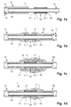
- FIG. 1a - 1c various intermediate stages are shown, which are run through when carrying out a first method according to the invention.
- Fig. 1d shows a first producible by the inventive method arrangement 1.
- a first plastic tube 10 shown in longitudinal section.
- the first plastic tube 10 is cylindrical and has an inner diameter 13 of, for example, 0.7 mm at a wall thickness 14 of z. B. 0.1 mm and consists of polyethylene terephthalate (PET).
- PET polyethylene terephthalate
- the outer diameter 31 of the inner tube 30 corresponds approximately to the inner diameter 13 of the first Kunststoffrschreibchens 10th
- a cylindrical polyimide tube 50 as a tubular connecting piece.
- the inner diameter of the polyimide tube 50 corresponds approximately to the inner diameter 13 of the first plastic tube 10.
- a first flange 51.1 protrudes from the outer lateral surface of the first plastic tube 10.
- the first flange 51.1 has a semi-circular cross-section and completely circumscribes the polyimide tube 50, which is shown in FIG Fig. 1a however, is not visible.
- a second flange 52.1 protrudes from the outer lateral surface of the polyimide tube 50.
- the second flange 52.1 like the first flange 51.1, has a semicircular cross-section and completely circumscribes the polyimide tube 50, which is shown in FIG Fig. 1a also not visible.
- Fig. 1b shows the situation after the first end 51 of the polyimide tube 50 has been inserted into the first plastic tube 10 and a second plastic tube 20 has been pushed onto the second end 52 of the polyimide tube 50.
- the first end 51 of the polyimide tube 50 is present in the end region 11 of the first plastic tube 10.
- the end portion 11 of the first plastic tube 10 thus completely surrounds the first end of the polyimide tube 50.
- the end region 11 of the first plastic tube 10 projects beyond the first flange 51.1 of the polyimide tube 50. Because of the inserted polyimide tube 50, the end region 11 of the first plastic tube 10 is slightly widened in the radial direction.
- a second plastic tube 20 is pushed over the second end 52 of the polyimide tube 50.
- the second plastic tube 20 protrudes coaxially in the longitudinal direction over the second flange 52 of the Polyimidrschreibchens 50.
- the second plastic tube 20 is also cylindrical, z. B. made of nylon and has an inner diameter 23 of, for example, 0.7 mm at a wall thickness 24 of z. B. 0.1 mm.
- the end portion 21 of the second plastic tube 20 is also slightly expanded due to the inserted Polyimidrschreibchens 50 in the radial direction. Accordingly, the first plastic tube 10 and the second plastic tube 20 have the same dimensions with respect to their diameters 13, 23 and wall thicknesses 14, 24 and are located coaxially with their end faces.
- An elastic modulus of the polyimide tube 50 is greater than a modulus of elasticity of the first plastic tube 10, while a modulus of elasticity of the second plastic tube 20 is smaller than the modulus of elasticity of the first plastic tube 10.
- Fig. 1b shows the situation after the end portion 11 of the first plastic tube 10 has been pushed over the end portion 21 of the second plastic tube 20 in the longitudinal direction.
- the first plastic tube 10 projects longitudinally beyond the second end 52 of the polyimide tube 50 and beyond the widened end region 21 of the second plastic tube 20.
- the end region 11 of the first plastic tube 10 therefore completely surrounds the end region 21 of the second plastic tube 20 and is partially additionally widened in the overlap region in the radial direction.
- a rear region 12 of the first plastic tube 10 which adjoins the end region 11 also surrounds the region of the polyimide tube 50 which is not surrounded by the second plastic tube 20.
- a shrink tube 40 is loosely arranged around the end portion 11 and the rear portion 12 of the first plastic tube 10.
- the shrink tube 40 completely surrounds the flared regions of the two plastic tubes 10, 20.
- Fig. 1d is a first inventive arrangement 1 of the two plastic tubes 10, 20 and the polyimide tube 50 after the conversion process shown.
- the in Fig. 1c illustrated shrink tube 40 was removed after the forming process again.
- the end portion 21 of the second plastic tube 20 is formed on the region of the second end 52 of the Polyimidrschreibchens 50 and adhesively connected thereto. Since the end portion 21 of the second plastic tube 20 is also formed on the second flange 52.1, there is also a positive connection between the end portion 21 of the second plastic tube 20 and the polyimide tube 50.
- the end portion 11 of the first plastic tube 10 is formed from the outside to the end portion 21 of the second plastic tube 20 and adhesively connected thereto.
- the rear portion 12 of the first plastic tube 10 is formed on the first end 51 of the Polyimidrschreibchens 50 and thus also on the first flange 51.1, whereby an adhesive and positive connection between the first plastic tube 10 and polyimide tube 50 is present.
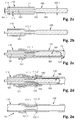
- FIG. 2a - 2d Various intermediate stages are shown, which are run through when carrying out a second inventive method.
- Fig. 2e is a second producible by the inventive method 2 arrangement shown.
- FIG. 2a On the left side, an end region 111 of a first cylindrical plastic tube 110 is shown in longitudinal section.
- the first plastic tube 110 has an inner diameter 113 of, for example, 0.7 mm at a wall thickness 114 of z. B. 0.1 mm and consists of polyethylene terephthalate (PET).
- An outer portion 181.1 of the end portion 181 of the cylindrical wire piece 180 measures approximately 0.5 mm, which corresponds to approximately 71% of the inner diameter 113 of the first plastic tube 110.
- the cylindrical piece of wire merges into a conically widening transition region 182, which in turn is followed by a thickened region 183 of the cylindrical wire piece 180.
- the outer diameter 183.1 of the thickened portion of the cylindrical Wire piece 180 measures approximately 0.7 mm and thus substantially corresponds to the inner diameter 113 of the first plastic tube 110.
- Fig. 2b shows the situation after the end portion 111 of the first plastic tube 110 has been formed on the end portion 181 of the cylindrical wire piece 180 and thereby converted into a connection piece 111.1.
- the inner diameter of the connecting piece 111.1 thus corresponds to the outer diameter of the end portion 181 of the cylindrical wire piece 180 and has a tapered outer diameter and a tapered inner diameter compared to the remaining portions of the first plastic tube 110.
- Fig. 2c shows the situation after a second plastic tube 120 has been coaxially pushed over the thickened portion 183 of the cylindrical wire piece 180 and the connecting piece 111.1 of the first plastic tube 110.
- the second plastic tube 120 is also cylindrical, consists for. B. of nylon and has an inner diameter 123 of, for example, 0.7 mm at a wall thickness 124 of z. B. 0.1 mm.
- An end region 121 of the second plastic tube protrudes in the longitudinal direction beyond the connection piece 111.1 of the first plastic tube 110 and lies behind the connection piece 111.1 on a non-tapered region of the first plastic tube 110.
- the end region 121 of the first plastic tube 120 is slightly widened in the radial direction.
- An elastic modulus of the second plastic tube 120 is smaller than a modulus of elasticity of the first plastic tube 110.
- Fig. 2d shows the situation after the cylindrical wire piece 180 has been partially pushed in the longitudinal direction in the deformed end portion 111.1 of the first plastic tube 110 inside.
- the conical transition region 182 of the cylindrical wire piece 180 is present in a region of a free end 111.2 of the connecting piece 111.1.
- the free end 111.2 of the connection piece 111.1 is substantially conically widened and pressed against the surrounding second plastic tube 120 from the inside.
- the second plastic tube 120 In the region of the widened free end 111.2 of the first plastic tube 110, which is surrounded by the second plastic tube 120, the second plastic tube 120 has a bulged region 122 into which the widened end 111.2 of the first plastic tube 110 engages.
- a shrink tube 140 is loosely arranged, which completely surrounds an overlap region of the two plastic tubes.
- Fig. 2e is a second inventive arrangement 101 from the two plastic tubes 110, 120 shown after the forming process.
- the end region of the second plastic tube 120 is now in the form of a deformed end region 121.1, which is formed on the first plastic tube 110 in a front region from the outside to the connection piece 111.1 of the first plastic tube 110 and behind the connection piece 111.1. Further behind, the second plastic tube 120 has a reshaped bulged region 122. 1, which is formed from the outside on the widened and deformed free end 111. 3 of the first plastic tube 110.
- connection piece 111.1 of the first plastic tube 110 and the second plastic tube before an adhesive and at the same time form-fitting connection, which withstands high tensile loads.
- the second arrangement 102 is z. B. part of a medical catheter 102, which in Fig. 4 is shown.
- Fig. 3 shows a third inventive arrangement 201, which was prepared substantially like the first arrangement 1 and z. B. is part of a medical catheter.
- a helical spring 250 was designed as a tubular one Connector used to connect a first plastic tube 210 and a second plastic tube 220.
- the coil spring 250 consists for example of stainless steel wire with a wire diameter 254 of z. B. 0.1 mm.
- the inner diameter of the coil spring is constant over an entire length and measures, for example, about 0.7 mm, while the individual turns of the coil spring 250 a distance 253 of z. B. 0.03 mm. Overall, the coil spring 250 has ten turns.
- the first plastic tube 210 is cylindrical and has an inner diameter of, for example, 0.7 mm with a wall thickness of z. B. 0.1 mm and consists of polyethylene terephthalate (PET).
- the second plastic tube 20 is also cylindrical, consists for. B. nylon and knows an inner diameter 23 of, for example, 0.7 mm at a wall thickness 24 of z. B. 0.1 mm.
- An elastic modulus of the second plastic tube 220 is smaller than a modulus of elasticity of the first plastic tube 210.
- a rear region 212 of the first plastic tube lying behind an end region 211 of the first plastic tube 210 is coaxially formed externally on a region of the first end 251 of the helical spring 250 or on six first turns of the helical spring 250.
- An end portion 221 of the second plastic tube 220 is also coaxially formed externally with a portion of the second end 252 of the coil spring 250 and with the four remaining turns of the coil spring 250, respectively. Due to the Anformung the coil spring 250 is partially embedded in both the first plastic tube 210 and the second plastic tube 220, wherein the coil spring 250 is approximately to a depth of half the wire diameter 254 of the coil spring 250 in the two plastic tubes 210, 220 embedded. Thus, between the two plastic tubes 210, 220 and the coil spring 250 both an adhesive, as well as a positive connection.
- the end portion 211 of the first plastic tube 210 which connects stepwise to the rear portion 212 of the first plastic tube, is also molded from the outside to the end portion 221 of the second plastic tube 220 and adhesively connected thereto.
- the helical spring 250 guarantees, in particular with respect to a longitudinal direction of the third arrangement 201 according to the invention, a high bending flexibility, but at the same time a high tensile strength of the third arrangement 201 is given.
- the third arrangement 102 is therefore particularly suitable in the region of the foremost 30 cm of a catheter, since this area of the catheter must have a high bending flexibility.
- Fig. 4 shows a medical catheter 102, which the second assembly 101 from Fig. 2e includes.
- the two connected plastic tubes 110, 120 which are the in Fig. 2e form a second arrangement 102 shown in detail, are in the form of a deformed and dimensionally stable spiral, which was formed by a preliminary heat treatment at 50 ° C.
- a catheter tip 195 is also arranged in a conventional manner.
- Fig. 1c and 2d shown intermediates are subjected to a forming process.
- heat shrink tubing 40, 140 from the Fig. 1c and 2d For example, blown with hot air. It is important that the reshaped plastic tubes are heated sufficiently so that at least a melting of the plastic tube occurs.
- the required process parameters such as temperature and duration of blowing depend on the one hand on the material of the plastic tubes used and on the other hand on the hot air source used.
- Optimal process parameters can, for. B. can be determined in a simple manner in the context of testing.
- a polyimide tube unstructured on the outside can also be used without flanges.
- an adhesive connection between plastic tube and polyimide tube is essentially formed.
- a polyimide tube which has an external thread and / or grooves or the use of a tube made of a different material, which has a high strength and dimensional stability even at higher temperatures.
- a tube for example made of a plastic, which is reinforced with a wire helix and / or fiber materials.
- tubular connecting piece or the polyimide tube 50 and / or the helical spring 250 have regions with different inner and / or outer diameters.
- plastic tubes with different inside and / or outside diameters are to be connected to one another by the method according to the invention.
- illustrated methods can also be carried out without an inner tube 30.
- the inner diameter of the Polyimidrschreibchens 50 may be less or greater than the inner diameter of the plastic tube in this case.
- the coil spring 250 can be made Fig. 3 have a smaller or larger inner diameter than the plastic tubes.
- the cylindrical wire piece 180 from Fig. 2a can z. B. instead of the conically widening transition region 182 also have a differently shaped transition region, which z. B. is formed substantially step-like. Also conceivable is the use of a cylindrical piece of wire whose end portion is completely conical.
- imaged medical catheters 102 it is also possible for imaged medical catheters 102 to have more than two interconnected plastic tubes. Instead of or in addition to the arrangement 101, the medical catheter 102 z. As well as other compounds contained between plastic tubes. This can z. B. by in the Fig. 1a - 1d and in the Fig. 2a - 2e Illustrated method can be produced. In particular, in the area of the tip while the connection of the plastic tube by a coil spring, such. In Fig. 3 shown, advantageous because this type is characterized in particular by a high bending flexibility.
- balloons which z. B. may be present as tubular plastic elements to attach to a catheter shaft.
- the method according to the invention is also suitable for the production of balloon catheters.
Landscapes
- Health & Medical Sciences (AREA)
- Engineering & Computer Science (AREA)
- Mechanical Engineering (AREA)
- Life Sciences & Earth Sciences (AREA)
- Chemical & Material Sciences (AREA)
- Animal Behavior & Ethology (AREA)
- General Health & Medical Sciences (AREA)
- Public Health (AREA)
- Veterinary Medicine (AREA)
- Chemical Kinetics & Catalysis (AREA)
- Epidemiology (AREA)
- Heart & Thoracic Surgery (AREA)
- General Engineering & Computer Science (AREA)
- Surgery (AREA)
- Pulmonology (AREA)
- Anesthesiology (AREA)
- Biomedical Technology (AREA)
- Hematology (AREA)
- Medicinal Chemistry (AREA)
- Materials Engineering (AREA)
- Dermatology (AREA)
- Oral & Maxillofacial Surgery (AREA)
- Transplantation (AREA)
- Vascular Medicine (AREA)
- Biophysics (AREA)
- Media Introduction/Drainage Providing Device (AREA)
- Branch Pipes, Bends, And The Like (AREA)
- Polymers & Plastics (AREA)
- Organic Chemistry (AREA)
- Lining Or Joining Of Plastics Or The Like (AREA)
Abstract
Description
- Die Erfindung betrifft ein Verfahren zum koaxialen Verbinden eines ersten Kunststoffröhrchens mit einem zweiten Kunststoffröhrchen, welche Kunststoffröhrchen insbesondere als Bestandteile eines medizinischen Katheters vorgesehen sind, wobei die beiden Kunststoffröhrchen über ein rohrförmiges Verbindungsstück verbunden werden. Des Weiteren bezieht sich die Erfindung auf eine Verwendung des Verfahrens bei der Herstellung eines Katheters und auf eine Anordnung aus zwei miteinander verbundenen Kunststoffröhrchen.
- Insbesondere bei der Herstellung von medizinischen Kathetern ist es notwendig, Kunststoffröhrchen mit unterschiedlichen Materialeigenschaften miteinander zu verbinden, um verschiedene Bereiche des Katheters optimal an die jeweiligen Erfordernisse anzupassen. Um eine gute Einführbarkeit eines Katheters zu gewährleisten, wird der Spitzenbereich des Katheters im Allgemeinen aus einem relativ flexiblen Kunststoffröhrchen ausgebildet, während die dahinter liegenden Abschnitte des Katheters aus steiferen Kunststoffröhrchen bestehen.
- Die verschiedenartigen Kunststoffröhrchen werden dabei meist miteinander verklebt und/oder miteinander verschweisst.
- Ein Verschweissen von Kunststoffröhrchen ist aber im Allgemeinen nur möglich, wenn die zu verbindenden Kunststoffröhrchen bzw. deren Polymermaterialien bezüglich der chemischen Struktur sehr ähnlich sind. In der
US 4,563,181 ist beispielsweise eine Stossverschweissung eines Katheterschafts aus Nylon (Polyamid) mit einer Katheterspitze aus einem relativ weichen und mit Nylon kompatiblen Polyether-Polyamid-Copolymer beschrieben. Ein derartiges Verfahren basiert jedoch auf kompatiblen Materialkombinationen, welche meist in aufwändigen Entwicklungsprozessen ermittelt werden müssen. - Beim Verkleben von Kunststoffröhrchen besteht zwar eine grössere Flexibilität, das präzise Aufbringen des Klebstoffs, insbesondere bei den geringen Durchmessern der für Katheter geeigneten Kunststoffröhrchen, ist jedoch ebenfalls aufwändig.
- Es besteht daher, insbesondere für die Herstellung von medizinischen Kathetern, nach wie vor Bedarf nach einem Verfahren, welches eine einfachere und sichere Verbindung von Kunststoffröhrchen auch aus chemisch unterschiedlichen Materialien ermöglicht.
- Aufgabe der Erfindung ist es daher, ein dem eingangs genannten technischen Gebiet zugehörendes Verfahren bereit zu stellen, welches flexibler anwendbar ist und eine einfache und gleichzeitig sichere Verbindung von Kunststoffröhrchen, insbesondere bei der Herstellung von medizinischen Kathetern, ermöglicht.
- Die Lösung der Aufgabe ist durch die Merkmale des Anspruchs 1 definiert. Gemäss der Erfindung werden das erste Kunststoffröhrchen und/oder das zweite Kunststoffröhrchen in einem Umformprozess von aussen an das rohrförmige Verbindungsstück angeformt, so dass eine adhesive und/oder formschlüssige Verbindung ausgebildet wird.
- Unter einem Kunststoffröhrchen wird in diesem Rahmen ein dünnes Rohr aus einem Kunststoff verstanden, welches bevorzugt einen Durchmesser von höchstens 3 mm, besonders bevorzugt einen Durchmesser von höchstens 2 mm, und insbesondere bevorzugt einen Durchmesser von höchstens 1 mm aufweisst.
- Eine Wandstärke der Kunststoffröhrchen misst insbesondere höchstens 0.5 mm, besonders bevorzugt höchstens 0.2 mm, und insbesondere bevorzugt höchstens 0.1 mm.
- Der Begriff Umformprozess bzw. Umformen bezieht sich in diesem Zusammenhang auf einen Prozess, bei welchem ein Körper, z. B. ein Kunststoffröhrchen, gezielt plastisch verformt und in eine neue Form gebracht wird, wobei das Volumen und die Masse des umgeformten Körpers erhalten beleibt.
- Grundsätzlich wird wenigstens eines der beiden zu verbindenden Kunststoffröhrchen durch den erfindungsgemässen Umformprozess mit dem rohrförmigen Verbindungsstück verbunden. Es liegt durchaus im Rahmen der Erfindung, dass das andere Kunststoffröhrchen, falls dies zweckmässig ist, durch eine andere Verbindungstechnik, z. B. durch Stoffschluss, mit dem rohrförmigen Verbindungsstück verbunden wird. Auch möglich ist die Verwendung eines ersten Kunststoffröhrchens, welches an einem Ende bereits über ein rohrförmiges Verbindungsstück verfügt oder die Ausbildung eines rohrförmigen Verbindungsstücks in einem Endbereich des ersten Kunststoffröhrchens.
- Während dem Umformprozess findet eine eigentliche plastische Verformung des ersten und/oder des zweiten Kunststoffröhrchen ein. Durch den Umformprozess werden die Grenzflächenschichten der inneren Bereiche des ersten und/oder des zweiten Kunststoffröhrchens in direkten Kontakt mit der Grenzflächenschicht des äusseren Bereichs des rohrförmigen Verbindungsstücks gebracht. Da während dem Umformprozess die Kunststoffröhrchen an das rohrförmige Verbindungsstück bzw. an dessen äussere Kontur angeformt werden, werden die Kontaktflächen der Grenzflächenschichten der Kunststoffröhrchen und der Grenzflächenschichten des rohrförmigen Verbindungsstücks maximiert. Dadurch wird eine adhesive Verbindung bzw. ein mechanischer Zusammenhalt zwischen den Kunststoffröhrchen und dem rohrförmigen Verbindungsstück erhalten, welcher insbesondere durch Verklammerungen auf mikroskopischer Skala und/oder atomare und/oder molekulare Wechselwirkungen zwischen den Grenzflächenschichten der Kunststoffröhrchen und des rohrförmigen Verbindungsstücks beruht.
- Derartige adhesive Verbindungen sind insbesondere auch fluiddicht, womit auf eine Abdichtung der Verbindung durch zusätzliche Dichtmassen, z. B. Klebstoffe, verzichtet werden kann. Dies ist insbesondere bei medizinischen Kathetern von Vorteil.
- Je nach Ausgestaltung des äusseren Bereichs des rohrförmigen Verbindungsstücks kann während dem Umformprozess auch eine formschlüssige Verbindung auf makroskopischer Skala gebildet, welche insbesondere zusätzlich zur adhesiven Verbindung die mechanische Stabilität der Verbindung zwischen den Kunststoffröhrchen und dem rohrförmigen Verbindungsstück erhöht.
- Durch den erfindungsgemässen Umformprozess lassen sich klebstofffreie und mechanisch stabile Verbindungen zwischen den Kunststoffröhrchen und dem rohrförmigen Verbindungsstück bilden. Dies ist insbesondere bei Kunststoffröhrchen, welche einen Durchmesser von höchstens 3 mm aufweisen, von grossem Vorteil. So ist z. B. das gleichmässige und präzise Anbringen von Klebstoff bei derartig dünnen Kunststoffröhrchen in der Praxis relativ aufwändig. Zudem besteht die Gefahr, dass beim Anbringen des Klebstoffs dieser versehentlich ins Innere des Kunststoffröhrchens gelangt. Das Entfernen des ungewollt in das Kunststoffröhrchen eingebrachten Klebstoffs ist dann entsprechend schwierig und mühsam. Entsprechend müssen auch Schweissvorgänge an derartig dünnen Kunststoffröhrchen unter anderem aufgrund der geringen Wandstärken sehr präzise durchgeführt werden, damit die Kunststoffröhrchen nicht beschädigt werden. Zudem stellt das Verschweissen von Kunststoff gewisse Anforderungen an die verwendeten Materialien, da sich nicht alle Kunststoffe untereinander verschweissen lassen. Das Verschweissen von Kunststoff mit anderen Materialien, wie z. B. Metall, ist zudem nicht möglich, was die Materialwahl für das rohrförmige Verbindungsstück, welches nicht zwingend aus einem Kunststoff bestehen muss, einschränkt.
- Da die Kunststoffröhrchen von aussen an das rohrförmige Verbindungselement angeformt werden, kann das rohrförmige Verbindungselement insbesondere vollständig von den Kunststoffröhrchen umhüllt bzw. umfasst werden. Damit werden allfällige Kanten und/oder Vorstände des rohrförmigen Verbindungsstück von den Kunststoffröhrchen abgedeckt. Kantenbereiche der Kunststoffröhrchen selbst können z. B. während dem erfindungsgemässen Umformprozess insbesondere abgerundet und/oder keilförmig auslaufend ausgebildet werden. Dies kann z. B. bei Kathetern von grossem Vorteil sein, da diese durch empfindliche und teilweise enge Hohlorgane des menschlichen und/oder tierischen Körpers geführt werden müssen. Vorstände oder Kanten an der Verbindungsstelle würden die Hohlorgane beschädigen bzw. verletzen.
- Es hat sich gezeigt, dass die erfindungsgemäss herstellbaren Verbindungen eine hohe mechanische Stabilität aufweisen und insbesondere auch gegenüber Zugbelastungen äusserst stabil sind.
- Somit bietet das erfindungsgemässe Verfahren, insbesondere gegenüber dem Verschweissen und/oder Verkleben von Kunststoffröhrchen, wesentliche Vorteile und ist zudem auch bei unterschiedlichen Materialien flexibel einsetzbar. Da das erfindungsgemässe Verfahren speziell bei sehr dünnen Kunststoffröhrchen vorteilhaft ist, eignet es sich im Besonderen für die Herstellung von medizinischen Kathetern.
- Bevorzugt werden das erste Kunststoffröhrchen und/oder das zweite Kunststoffröhrchen während dem Umformprozess durch eine Wärmebehandlung erweicht und durch eine in einer radialen Richtung einwirkende Presskraft an das rohrförmige Verbindungsstück angeformt. Durch die Wärmebehandlung wird die Grenzschicht des ersten und/oder des zweiten Kunststoffröhrchens erweicht, wodurch sich die Anformung an das rohrförmige Verbindungsstück vereinfacht. Die Presskraft, welche insbesondere während der Wärmebehandlung auf das erste und/oder das zweite Kunststoffröhrchen einwirkt, kann dieses bestmöglich an die äussere Kontur des rohrförmigen Verbindungsstücks angeformt werden, da das Kunststoffröhrchen in diesem Fall in erweichtem Zustand vorliegt. Damit bildet sich eine grösstmögliche Adhäsion zwischen den Kunststoffröhrchen und dem rohrförmigen Verbindungsstück aus.
- Die Presskraft wirkt mit Vorteil in sämtliche radiale Richtungen auf das Kunststoffröhrchen ein, so dass das Kunststoffröhrchen aus allen Richtungen gleichmässig an das rohrförmige Verbindungsstück angepresst wird.
- Zur Durchführung des Umformprozesses ist insbesondere ein Schrumpfschlauch geeignet, welcher z. B. aus einem Kunststoff wie beispielsweise Polyolefine, Polyvinylchlorid oder Teflon besteht. Der Schrumpfschlauch kann direkt über die Bereiche der Kunststoffröhrchen geschoben werden, welche im Umformprozess an das rohrförmige Verbindungsstück angeformt werden sollen. Durch Zufuhr von Wärme, beispielsweise in Form von Heissluft und/oder elektromagnetischer Strahlung, kann der Schrumpfschlauch erhitzt werden, so dass er sind in radialer Richtung stark zusammenzieht und eine Presskraft auf die Kunststoffröhrchen einwirkt. Durch die zugeführte Wärme können gleichzeitig die Kunststoffröhrchen erweicht und/oder angeschmolzen werden. Der Schrumpfschlauch kann nach dem Umformprozess wieder entfernt werden oder aber auf den verbundenen Kunststoffröhrchen belassen werden. In letzterem Fall kann der Schrumpfschlauch als zusätzliche Stabilisierung und/oder als Schutz vor die Verbindungsstelle dienen.
- Grundsätzlich liegt es aber auch im Rahmen der Erfindung, zum Umformen während dem Umformprozess lediglich eine Presskraft einwirken zu lassen, falls dies aufgrund der Materialeigenschaften des Kunststoffröhrchens möglich ist. Dies geht jedoch zu Lasten einer bestmöglichen Adhäsion zwischen Kunststoffröhrchen und rohrförmigem Verbindungsstück.
- Insbesondere wird vor dem Umformprozess ein Endbereich des ersten Kunststoffröhrchens koaxial über ein erstes Ende des rohrförmigen Verbindungsstücks geschoben und ein Endbereich des zweiten Kunststoffröhrchens wird koaxial über ein zweites Ende des rohrförmigen Verbindungsstücks geschoben. Das rohrförmige Verbindungsstück liegt dabei z. B. als separater Hohlzylinder bzw. als kurzes Rohrstück vor. Damit können die beiden zu verbindenden Kunststoffröhrchen vor dem Umformprozess bereits in ihrer vorgesehenen Lage angeordnet werden. Anschliessend kann der Umformprozess z. B. für beide Kunststoffröhrchen gleichzeitig durchgeführt werden, was insbesondere Zeit spart.
- Es ist aber auch denkbar, in einem ersten Schritt den Endbereich des ersten Kunststoffröhrchens mit dem ersten Ende des rohrförmigen Verbindungsstücks zu verbinden und erst danach den Endbereich des zweiten Kunststoffröhrchens mit dem zweiten Ende des rohrförmigen Verbindungsstücks zu verbinden.
- Grundsätzlich ist es auch möglich, ein erstes Kunststoffröhrchen, welches mit einem weiteren und aus dem ersten Kunststoffröhrchen herausragenden Innenröhrchen bestückt ist, mit dem zweiten Kunststoffröhrchen zu verbinden. Hierfür weist das rohrförmigen Verbindungsstück insbesondere einen Innendurchmesser auf, welcher wenigstens gleich gross ist wie der Aussendurchmesser des Innenröhrchens des ersten Kunststoffröhrchens. Das rohrförmige Verbindungsstück kann in diesem Fall auf das Innenröhrchen aufgeschoben werden und anschliessend kann das erste Ende des rohrförmigen Verbindungsstücks in den Endbereich des ersten Kunststoffröhrchens eingeführt werden. Danach kann das zweite Kunststoffröhrchen zuerst über das aus dem ersten Kunststoffröhrchen herausragende Innenröhrchen und dann über das zweite Ende des rohrförmigen Verbindungsstücks geschoben werden.
- Bevorzugt ist ein Elastizitätsmodul des rohrförmigen Verbindungsstücks grösser als ein Elastizitätsmodul des ersten Kunststoffröhrchens und grösser als ein Elastizitätsmodul des zweiten Kunststoffröhrchens. Eine derartige Anordnung ist insbesondere gegenüber Zugbelastungen stabiler. Unter Zugbelastung haben die Kunststoffröhrchen nämlich die Tendenz, sich im Durchmesser zusammen zu ziehen. Dies erzeugt eine Kraft in radialer Richtung, welche auf das rohrförmige Verbindungsstück einwirkt. Je grösser das Elastizitätsmodul des rohrförmigen Verbindungsstücks, desto besser kann dieses der in radialer Richtung einwirkenden Kraft entgegen halten, ohne selber stark verformt zu werden. Damit wird unter Zugbelastung zwischen den Kunststoffröhrchen und dem rohrförmigen Verbindungsstück zusätzlich ein Kraftschluss erzeugt, welcher die mechanische Festigkeit der Verbindung steigert.
- Grundsätzlich ist es auch möglich, ein rohrförmiges Verbindungsstück einem geringerem Elastizitätsmodul vorzusehen. Dies kann unter Umständen vorteilhaft sein, um die Flexibilität der Verbindungsstelle zu erhöhen. Allerdings entfällt in diesem Fall der Vorteil des zusätzlichen Kraftschlusses zwischen rohrförmigen Verbindungsstück und Kunststoffröhrchen.
- Bevorzugt besteht das verwendete erste Kunststoffröhrchen aus einem ersten thermoplastischen Material, beispielsweise aus Polyethylentherephtalat, und das zweite Kunststoffröhrchen aus einem zweiten thermoplastischen Material, beispielsweise aus Nylon. Derartige thermoplastische Materialien lassen sich durch Wärmebehandlung problemlos erweichen bzw. anschmelzen und in erweichtem Zustand umformen. Da das Erweichen bzw. Anschmelzen des thermoplastischen Materials reversibel ist, werden die Materialeigenschaften der Kunststoffröhrchen durch den Umformprozess nicht verändert und/oder beeinträchtigt.
- Anordnungen aus Kunststoffröhrchen aus derartigen thermoplastischen Materialen sind insbesondere für medizinische Katheter geeignet. Dabei kann beispielsweise ein Kunststoffröhrchen aus Polyethylentherephtalat als Katheterschaft und ein Kunststoffröhrchen aus Nylon im Bereich der Katheterspitze angeordnet sein. Da Kunststoffröhrchen aus Polyethylenetherephtalat bei gleichen Dimensionen im Allgemeinen steifer sind als Kunststoffröhrchen aus Nylon, lassen sich derartig ausgebildete Katheter gut in Hohlorgane einführen.
- Grundsätzlich ist es aber auch denkbar, Kunststoffröhrchen aus anderen umformbaren Kunststoffen einzusetzen.
- Es kann auch vorteilhaft sein, den Endbereich des ersten Kunststoffröhrchens vor dem Umformprozess zusätzlich koaxial über den Endbereich das zweiten Kunststoffröhrchen zu schieben. Der Endbereich des ersten Kunststoffröhrchens wird in diesem Fall während dem Umformprozess wenigstens teilweise an den Endbereich des zweiten Kunststoffröhrchens angeformt. Damit kann insbesondere verhindert werden, dass zwischen den beiden zu verbindenden Kunststoffröhrchen ein Spalt gebildet wird, wodurch die Dichtigkeit der Verbindung zwischen den beiden Kunststoffröhrchen verbessert wird. Es ist aber auch möglich, die beiden zu verbindenden Kunststoffröhrchen stirnseitig aneinander zu schieben. Die Verbindung zwischen den beiden Kunststoffröhrchen ist dann zwar unter Umständen weniger dicht, es ergibt sich aber der Vorteil, dass der Durchmesser der Verbindungsstelle insgesamt dünner ausfällt.
- Bevorzugt ist dabei ein Elastizitätsmodul des ersten Kunststoffröhrchens grösser als ein Elastizitätsmodul des zweiten Kunststoffröhrchens. Dies verbessert insbesondere die mechanische Festigkeit der direkten Verbindung zwischen den beiden Kunststoffröhrchen. Da sich das erste Kunststoffröhrchen, welches innerhalb des Endbereichs des zweiten Kunststoffröhrchen angeordnet ist, unter Zugbelastung weniger stark zusammenzieht als das darüber liegende zweite Kunststoffröhrchen, wird unter Zugbelastung zusätzlich eine kraftschlüssige Verbindung direkt zwischen dem ersten Kunststoffröhrchen und dem zweiten Kunststoffröhrchen erzeugt.
- Es ist aber auch möglich, ein erstes Kunststoffröhrchen mit einem Elastizitätsmodul einzusetzen, welches geringer ist als das Elastizitätsmodul des zweiten Kunststoffröhrchens. In diesem Fall entfällt jedoch die Verbesserung der mechanischen Festigkeit unter Zugbelastung.
- Insbesondere besteht das verwendete rohrförmige Verbindungsstück aus Polyimid. Polyimid als Material für das rohrförmige Verbindungsstück hat sich als vorteilhaft erwiesen, da Polyimid ein relativ grosses Elastizitätsmodul aufweist und damit schwer deformierbar ist. Gleichzeitig ist aber eine gewisse Flexibilität vorhanden, welche insbesondere bei der Verbindung von flexiblen Kunststoffröhrchen wünschenswert ist. Des Weiteren ist die Schrumpfung von Polyimid unter Wärmeeinwirkung im hier interessierenden Temperaturbereich äusserst gering. Ein rohrförmiges Verbindungsstück auch Polyimid bleibt daher auch bei den während dem Umformprozess herrschenden Temperaturen äusserst formstabil.
- Grundsätzlich kann anstelle eines rohrförmigen Verbindungsstücks aus Polyimid auch ein Verbindungsstück aus Stahl oder sonst einem schwer deformierbaren Material verwendet werden, welches unter Wärmeeinwirkung möglichst wenig schrumpft.
- Insbesondere ist eine Wandung des rohrförmigen Verbindungsstücks mit einer eingebetteten Drahtwendel verstärkt. Während dem Umformprozess kann die Wandung des rohrförmigen Verbindungsstücks, welches z. B. aus einem thermoplastischen Material besteht, an die eingebettete Drahtwendel angeformt werden. Dadurch wird eine schraubenlinienförmige Struktur an der Aussenseite des rohrförmigen Verbindungsstücks gebildet. Das erste und/oder das zweite Kunststoffröhrchen werden in diesem Fall während dem Umformprozess an die schraubenlinienförmige Struktur angeformt, womit eine formschlüssige Verbindung zwischen den Kunststoffröhrchen und dem rohrförmigen Verbindungsstück ausgebildet wird. Dies verbessert die mechanische Festigkeit der Verbindung bzw. der Anordnung der Kunststoffröhrchen und des rohrförmigen Verbindungsstücks.
- Es ist aber auch möglich, auf eine eingebettete Drahtwendel zu verzichten und/oder rohrförmige Verbindungsstücke mit strukturierten Aussenseiten zu verwenden.
- In einer bevorzugten Variante weist daher das rohrförmige Verbindungsstück eine strukturierte äussere Mantelfläche auf. Die strukturierte äussere Mantelfläche kann beispielsweise Vorstände und/oder Rillen und/oder Schraubengewinde und/oder umlaufende Flansche umfassen. Da die Kunststoffröhrchen während dem Umformprozess an die strukturierte äussere Mantelfläche des rohrförmigen Verbindungsstücks angeformt werden, wird eine formschlüssige Verbindung zwischen Kunststoffröhrchen und rohrförmigem Verbindungsstück gebildet, welche die mechanische Festigkeit verbessert.
- Es ist aber auch möglich, rohrförmige Verbindungsstücke ohne strukturierte Aussenseiten bzw. Mantelflächen einzusetzen. Allerdings ist dabei die mechanische Festigkeit der Verbindung gegenüber einer strukturierten äusseren Mantelfläche vermindert.
- In einer weiteren vorteilhaften Variante wird als rohrförmiges Verbindungsstück eine Schraubenfeder verwendet, wobei die Schraubenfeder insbesondere aus metallischem Draht besteht. Schraubenfedern als rohrförmige Verbindungsstücke haben sich als vorteilhaft erwiesen, da sie zwar eine relativ hohe Biegeflexibilität bezüglich der Längsachse aufweisen, gleichzeitig aber in radialer Richtung nur wenig flexibel sind. Zudem weisen Schraubenfedern aufgrund der nebeneinander angeordneten Drahtwindungen eine strukturiert äussere Mantelfläche auf. Da die Schraubenfeder in radialer Richtung nur wenig flexibel ist, lassen sich die Kunststoffröhrchen im Umformprozess gut an die Schraubenfedern bzw. die einzelnen Drahtwindungen anformen. Dadurch kann in einfacher Art und Weise eine formschlüssige Verbindung zwischen Schraubenfeder und Kunststoffröhrchen hergestellt werden. Derartig hergestellte Anordnungen aus Kunststoffröhrchen, welche über eine Schraubenfeder verbunden sind, zeichnen sich durch eine hohe mechanische Festigkeit aus, sind aber bezüglich einer Längsrichtung dennoch relativ flexibel.
- Bevorzugt weisen einzelne Windungen der Schraubenfeder einen Abstand auf, welcher 10 - 50% eines Drahtdurchmessers der Schraubenfeder entspricht. Eine Anordnung aus Kunststoffröhrchen, welche über eine Schraubenfeder mit derartig beabstandeten einzelnen Windungen verbunden sind, zeichnet sich insbesondere durch eine optimale Flexibilität im Bereich der Verbindungsstelle aus. Insbesondere die Biegeflexibilität der Verbindungsstelle bezüglich einer Längsachse ist damit optimiert.
- Es ist aber grundsätzlich auch möglich, eine Schraubenfeder einzusetzen, bei welcher die einzelnen Drahtwindungen einen Abstand von mehr als 50% des Drahtdurchmessers der Schraubenfeder aufweisen. In diesem Fall besteht jedoch die Gefahr, dass während dem Umformprozess die Kunststoffröhrchen in den Innenbereich der Schraubenfeder hinein gedrückt werden. Zudem wird die Biegeflexibilität bezüglich der Längsachse durch den grösseren Abstand nicht mehr wesentlich verbessert. Auch geringere Abstände von weniger als 10% des Drahtdurchmessers sind prinzipiell möglich. Allerdings nimmt dann die Biegeflexibilität entsprechend ab.
- Es ist aber auch möglich, einzelne Windungen der Schraubenfeder aneinander anliegend anzuordnen. Dies kann vorteilhaft sein, wenn beispielsweise die innere Mantelfläche der Schraubenfeder möglichst gleichmässig ausgebildet sein soll. Insbesondere, falls die hergestellte Anordnung aus den mit der Schraubenfeder verbundenen Kunststoffröhrchen Bestandteil eines Führungsdrahtlumens eines medizinischen Katheters ist, kann dies vorteilhaft sein, da einzeln vorstehende und die Bewegung des Führungsdrahts hindernde Windungen der Schraubenfeder vermieden werden.
- Bei Verwendung eines separaten rohrförmigen Verbindungsstücks werden bevorzugt sowohl das erste Kunststoffröhrchen als auch das zweite Kunststoffröhrchen formschlüssig an das rohrförmige Verbindungsstück angeformt. Damit wird eine bezüglich mechanischer Festigkeit optimale Verbindung geschaffen.
- Grundsätzlich liegt es aber auch im Rahmen der Erfindung, lediglich das erste Kunststoffröhrchen oder das zweite Kunststoffröhrchen formschlüssig an das rohrförmige Verbindungsstück anzuformen. In diesem Fall kann das nicht formschlüssig verbundene Kunststoffröhrchen beispielsweise adhesiv befestigt werden. Ebenso liegt es im Rahmen der Erfindung, beide Kunststoffröhrchen ohne Formschluss, beispielsweise adhesiv mit dem rohrförmigen Verbindungsstück zu verbinden.
- In einer weiteren vorteilhaften Ausführungsform wird vor dem Umformprozess der erste Endbereich des ersten Kunststoffröhrchens zu einem Verbindungsstutzen umgeformt. Das rohrförmige Verbindungsstück besteht in diesem Fall aus einem zu einem Verbindungsstutzen umgeformten Endbereich des ersten Kunststoffröhrchens, wobei der Verbindungsstutzen bevorzugt im Wesentlichen einen geringeren Aussendurchmesser aufweist als das erste Kunststoffröhrchen. Der Verbindungsstutzen übernimmt in diesem Fall die Funktion des rohrförmigen Verbindungsstücks. Damit kann auf ein separates rohrförmiges Verbindungsstück verzichtet werden. Wie vorstehend erwähnt, kann das rohrförmige Verbindungsstück aber auch als separates Teil vorliegen.
- Bevorzugt ist dabei ein Elastizitätsmodul des ersten Kunststoffröhrchens grösser als ein Elastizitätsmodul des zweiten Kunststoffröhrchens. Da der Verbindungsstutzen in diesem Fall aus dem ersten Kunststoffröhrchen gebildet wird, weist der Verbindungsstutzen ein Elastizitätsmodul auf, welches grösser ist als das Elastizitätsmodul des zweiten Kunststoffröhrchens. Damit wird eine höhere mechanische Festigkeit der Verbindung zwischen dem Verbindungsstutzen und dem zweiten Kunststoffröhrchen erhalten. Unter Zugbelastung zieht sich das zweite und aussen liegende Kunststoffröhrchen zusammen und drückt in radialer Richtung auf den Verbindungsstutzen. Aufgrund des höheren Elastizitätsmoduls des Verbindungsstutzens zieht sich dieser weniger stark zusammen als das zweite Kunststoffröhrchen. Dies resultiert insgesamt in einer zusätzlichen kraftschlüssigen Verbindung zwischen dem zweiten Kunststoffröhrchen und dem Verbindungsstutzen.
- Prinzipiell kann auch das zweite Kunststoffröhrchen ein höheres Elastizitätsmodul aufweisen als das erste Kunststoffröhrchen. Allerdings besteht dabei die Gefahr, dass unter Zugbelastung der Verbindungsstutzen aus dem zweiten Kunststoffröhrchen heraus rutscht, da sich der Verbindungsstutzen unter Zugbelastung in diesem Fall stärker zusammenzieht als das zweite Kunststoffröhrchen.
- Bevorzugt wird bei der Umformung des ersten Kunststoffröhrchens zum Verbindungsstutzen ein Aussendurchmesser des Verbindungsstutzens verglichen mit dem Aussendurchmesser des ersten Kunststoffröhrchen im Wesentlichen verjüngt ausgebildet. Damit lässt sich das zweite Kunststoffröhrchen nachher einfacher über den Verbindungsstutzen schieben. Des Weiteren kann so der Aussendurchmesser der Verbindungsstelle minimiert werden, was insbesondere bei medizinischen Kathetern von Vorteil ist.
- Es ist aber prinzipiell auch denkbar, den Aussendurchmesser des Verbindungsstutzens verglichen mit dem Aussendurchmesser des ersten Kunststoffröhrchens grösser auszubilden. Dies kann z. B. vorteilhaft sein, um zusätzlich eine formschlüssige Verbindung zwischen den beiden Kunststoffröhrchen zu erzeugen.
- Zur Herstellung des Verbindungsstutzens wird bevorzugt ein Endabschnitt eines zylindrischen Drahtstücks in den ersten Endbereich des ersten Kunststoffröhrchens eingeführt und anschliessend der erste Endbereich des ersten Kunststoffröhrchens durch Umformung von aussen an den Endabschnitt des zylindrischen Drahtstücks angeformt. Die Verwendung eines derartigen Drahtstücks ermöglicht insbesondere die Herstellung eines Verbindungsstutzens mit gleichmässiger Wandstärke und klar definiertem Innendurchmesser.
- Ein Aussendurchmesser des Endabschnitts des zylindrischen Drahtstücks misst dabei insbesondere 60 - 80%, besonders bevorzugt 65 - 75%, des Innendurchmessers des ersten Kunststoffröhrchens vor der Ausbildung des Verbindungsstutzens.
- Es hat sich gezeigt, dass mit derartig dimensionierten Drahtstücken bei den meisten Kunststoffröhrchen sehr gute Ergebnisse bezüglich der Qualität der Verbindungsstutzen erreichbar sind. Insbesondere weisen derartig hergestellte Verbindungsstutzen Stabilitäten auf, welche mit der Stabilität der Kunststoffröhrchen als solche vergleichbar sind. Zudem wird sichergestellt, dass der Verbindungsstutzen eine ausreichende Durchlässigkeit aufweist und gleichzeitig eine signifikante Verjüngung im Vergleich mit dem Kunststoffröhrchen vor der Ausbildung des Verbindungsstutzens erzielbar ist.
- Insbesondere wird das zweite Kunststoffröhrchen vor dem Umformprozess koaxial und wenigstens über eine gesamte Länge des Verbindungsstutzens über diesen geschoben. Damit wird sichergestellt, dass während dem nachfolgenden Umformprozess eine maximale Kontaktfläche zwischen dem Verbindungsstutzen und den zweiten Kunststoffröhrchen gebildet wird, wodurch, wie vorstehend bereits erwähnt, die adhesive Verbindung bzw. der mechanische Zusammenhalt optimiert wird.
- Es ist aber auch möglich, das zweite Kunststoffröhrchen weiter zu schieben, so dass es über den Verbindungsstutzen hinaus über das erste Kunststoffröhrchen zu liegen kommt. Dies kann insbesondere dann von Vorteil sein, wenn der Verbindungsstutzen einen grösseren Aussendurchmesser aufweist als das erste Kunststoffröhrchen, da dann während dem Umformprozess zusätzlich eine formschlüssige Verbindung herstellbar ist.
- Es ist jedoch auch eine Anordnung praktikabel, bei welcher das zweite Kunststoffröhrchen lediglich teilweise über den Verbindungsstutzen geschoben wird. Je kürzer der gemeinsame Kontaktbereich zwischen zweitem Kunststoffröhrchen und dem Verbindungsstutzen ausfällt, desto geringer ist jedoch die adhesive Verbindung.
- Besonders bevorzugt wird ein freies Ende des Verbindungsstutzens vor dem Umformprozess aufgeweitet. Indem das freie Ende gegenüber den übrigen Bereichen des Verbindungsstutzens aufgeweitet ausgeformt wird, lässt sich im nachfolgenden Umformprozess eine formschlüssige Verbindung erzeugen, welche insbesondere den mechanischen Zusammenhalt zwischen Verbindungsstutzen und zweitem Kunststoffröhrchen verbessert.
- Es ist aber prinzipiell auch möglich, anstelle oder zusätzlich zum freien Ende einen anderen Bereich des Verbindungsstutzens aufzuweiten, welcher z. B. hinter dem freiem Ende des Verbindungsstutzens liegt. Auch möglich ist es, auf eine Aufweitung des Verbindungsstutzens ganz zu verzichten. Allerdings geht dies zu Lasten eines maximalen Zusammenhalts zwischen Verbindungsstutzen und zweitem Kunststoffröhrchen.
- Zur Aufweitung des freien Endes des Verbindungsstutzens wird vorteilhaft ein an den Endabschnitt des zylindrischen Drahtstücks anschliessender verdickter Bereich des zylindrischen Drahtstücks und/oder ein aufgeweiteter Übergangsbereich zum verdickten Bereich in einer Richtung zum ersten Kunststoffröhrchen hin in das freie Ende des Verbindungsstutzens hinein geschoben. Der Übergang zwischen dem Endabschnitt des zylindrischen Drahtstücks und dem verdickten Bereich des zylindrischen Drahtstücks ist dabei insbesondere konisch und/oder abgerundet ausgebildet, so dass der verdickte Bereich des zylindrischen Drahtstücks bestmöglich in das freie Ende des Verbindungsstutzens hinein geschoben werden.
- Es ist aber beispielsweise auch möglich, für die Aufweitung des Verbindungsstutzens einen konisch zulaufenden Draht einzusetzen und/oder das freie Ende des Verbindungsstücks durch Anschmelzen aufzuweiten.
- Bevorzugt entspricht ein Aussendurchmesser des verdickten Bereichs des zylindrischen Drahtstücks im Wesentlichen dem Innendurchmesser des ersten Kunststoffröhrchens vor der Herstellung des Verbindungsstutzens. Es hat sich gezeigt, dass ein derartig dimensioniertes Drahtstück besonders geeignet ist, um eine für eine formschlüssige Verbindung ausreichende Aufweitung des Verbindungsstutzens zu erzielen, ohne den Verbindungsstutzen während der Aufweitung zu beschädigen.
- Bevorzugt wird während dem Umformprozess das zweite Kunststoffröhrchen unter Ausbildung einer formschlüssigen Verbindung an den endseitig aufgeweiteten Verbindungsstutzen angeformt. Dadurch wird eine äusserst stabile Verbindung zwischen dem zweiten Kunststoffröhrchen und dem Verbindungsstutzen bzw. dem damit verbundenen ersten Kunststoffröhrchen erhalten.
- Mit Vorteil verbleiben während dem Umformprozess der Endabschnitt des zylindrischen Drahtstücks im Verbindungsstutzen und der aufgeweitete Übergangsbereich des zylindrischen Drahtstücks und/oder der verdickte Bereich des zylindrischen Drahtstücks im aufgeweiteten freien Ende des Verbindungsstutzens. Damit kann eine vorgegebene Durchlässigkeit der Verbindungsstelle garantiert werden, da sich der Verbindungsstutzen während dem Umformprozess auch bei Anwendung einer Presskraft und unter Wärmeeinfluss nicht weiter verjüngen kann. Dies ist insbesondere entscheidend, falls die Kunststoffröhrchen beispielsweise zur Fluidleitung und/oder als Führungskanal für einen Draht bei einem Katheter vorgesehen sind. Zudem wird damit garantiert, dass das zweite Kunststoffröhrchen optimal an den Verbindungsstutzen angeformt werden kann, da der Verbindungsstutzen innenseitig gestützt wird. Der verdickte Bereich des zylindrischen Drahtstücks im aufgeweiteten Ende des Verbindungsstutzens, garantiert insbesonders, dass sich der aufgeweitete Bereich während dem Umformprozess nicht wieder verjüngt.
- Damit wird die Ausbildung einer formschlüssigen Verbindung ermöglicht, wobei der Verbindungsstutzen an einem freien Ende insbesondere auch nach dem Umformprozess aufgeweitet vorliegt und das zweite Kunststoffröhrchen formschlüssig an den Verbindungsstutzen angeformt ist.
- Es ist aber auch denkbar, das zylindrische Drahtstück vor dem Umformprozess aus dem Verbindungsstutzen zu entfernen. Allerdings muss der Umformprozess dann entsprechend sehr genau kontrolliert werden, was unter Umständen aufwändig ist.
- In einer weiteren bevorzugten Variante werden das erste Kunststoffröhrchen und/oder das zweite Kunststoffröhrchen nach dem Umformprozess spiralförmig aufgewickelt und unter Anwendung von Wärme zu einer formstabilen Spirale geformt. Das erste Kunststoffröhrchen und/oder das zweite Kunststoffröhrchen liegt daher nach der Anwendung von Wärme in Form einer formstabilen Spirale vor. Damit lassen sich auch längere Kunststoffröhrchen platzsparend, beispielsweise in einer Verpackungshülle, verpacken und lagern. Da die aufgewickelte Spirale nach der Anwendung von Wärme formstabil ist, behält sie auch nach einem Entfernen der Verpackungshülle ihre spiralförmige Form bei. Eine unkontrolliertes Auseinanderrollen des Kunststoffröhrchens wird so wirksam verhindert. Es ist aber auch möglich, auf eine spiralförmige Aufwicklung und/oder die Ausbildung einer formstabilen Spirale zu verzichten.
- Insbesondere durch das erfindungsgemässe Verfahren lassen sich demnach Anordnungen herstellen, welche ein erstes Kunststoffröhrchen, das über ein rohrförmiges Verbindungsstück mit einem zweiten Kunststoffröhrchen verbunden ist, umfassen, wobei das erste Kunststoffröhrchen und/oder das zweite Kunststoffröhrchen von aussen an das rohrförmige Verbindungsstück angeformt und adhesiv und/oder formschlüssig mit dem Verbindungsstück verbunden ist.
- Derartige Anordnungen können insbesondere durch das erfindungsgemässe Verfahren mit geringen Aussendurchmessern ausgebildet werden. Damit sind die erfindungsgemässen Anordnungen und das erfindungsgemässe Verfahren im Besonderen geeignet zur Verwendung bei der Herstellung von medizinischen Kathetern.
- Aus der nachfolgenden Detailbeschreibung und der Gesamtheit der Patentansprüche ergeben sich weitere vorteilhafte Ausführungsformen und Merkmalskombinationen der Erfindung.
- Die zur Erläuterung des Ausführungsbeispiels verwendeten Zeichnungen zeigen:
- Fig. 1a
- Ein Längsschnitt durch ein erstes Kunststoffröhrchen mit einem daraus herausragenden Innenrohr, wobei ein rohrförmiges Verbindungsstück über das Innenrohr geschoben wurde;
- Fig. 1b
- Ein Längsschnitt durch das rohrförmige Verbindungsstück, welches in einen Endbereich eines ersten Kunststoffröhrchens und einen Endbereich eines zweiten Kunststoffröhrchens eingeschoben ist;
- Fig. 1c
- Ein Längsschnitt durch die Anordnung aus
Fig. 1b , wobei der Endbereich des ersten Kunststoffröhrchens zusätzlich über den Endbereich des zweiten Kunststoffröhrchens geschoben und von einem Schrumpfschlauch umgeben wurde; - Fig. 1d
- Ein Längsschnitt durch die Anordnung aus
Fig. 1c nach erfolgtem Umformprozess und Entfernung des Schrumpfschlauchs; - Fig. 2a
- Ein Längsschnitt durch ein in ein erstes Kunststoffröhrchen hinein ragendes zylindrisches Drahtstück;
- Fig. 2b
- Ein Längsschnitt durch die Anordnung aus
Fig. 2a nach erfolgter Umformung des Endbereichs des ersten Kunststoffröhrchens zu einem verjüngten Verbindungsstutzen; - Fig. 2c
- Ein Längsschnitt durch die Anordnung aus
Fig. 2b , wobei zusätzlich ein zweites Kunststoffröhrchen über das zylindrische Drahtstück und den Verbindungsstutzen geschoben wurde; - Fig. 2d
- Ein Längsschnitt durch die Anordnung aus
Fig. 2c , nachdem ein freies Ende des Verbindungsstutzens durch einen verdickten Bereich des zylindrischen Drahtstücks aufgeweitet und ein Schrumpfschlauch um die Verbindungsstelle angeordnet wurde; - Fig. 2e;
- Ein Längsschnitt durch die Anordnung aus
Fig. 2d nach erfolgtem Umformprozess und Entfernung des Schrumpfschlauchs; - Fig. 3
- Ein Längsschnitt durch eine Variante von
Fig. 1d , wobei als rohrförmiges Verbindungsstück eine Schraubenfeder angeordnet ist; - Fig. 4
- Ein zu einer formstabilen Spirale umgeformter medizinischer Katheter, welcher die Anordnung aus
Fig. 2e umfasst. - Grundsätzlich sind in den Figuren gleiche Teile mit gleichen Bezugszeichen versehen.
- In den
Fig. 1a - 1c sind verschiedene Zwischenstufen dargestellt, welche bei der Durchführung eines ersten erfindungsgemässen Verfahrens durchlaufen werden.Fig. 1d zeigt eine erste durch das erfindungsgemässe Verfahren herstellbare Anordnung 1. - Auf der linken Seite in
Fig. 1a ist ein Endbereich 11 eines ersten Kunststoffröhrchens 10 im Längsschnitt abgebildet. Das erste Kunststoffröhrchen 10 ist zylindrisch und weist einen Innendurchmesser 13 von beispielsweise 0.7 mm bei einer Wandstärke 14 von z. B. 0.1 mm auf und besteht aus Polyethylentherephtalat (PET). Im Innern des ersten Kunststoffröhrchens 10 ist ein koaxiales und zylindrisches Innenrohr 30 angeordnet, welches aus dem Endbereich 11 des ersten Kunststoffröhrchens 10 heraus ragt. Der Aussendurchmesser 31 des Innenrohrs 30 entspricht dabei in etwa dem Innendurchmesser 13 des ersten Kunststoffröhrchens 10. - Über einen aus dem ersten Kunststoffröhrchen 10 herausragenden Bereich des Innenröhrchens 30 ist als rohrförmiges Verbindungsstück koaxial ein zylindrisches Polyimidröhrchen 50 geschoben. Der Innendurchmesser des Polyimidröhrchens 50 entspricht ungefähr dem Innendurchmesser 13 des ersten Kunststoffröhrchens 10. Im Bereich des ersten Endes 51 des Polyimidröhrchens 50, welches dem ersten Kunststoffröhrchen 10 zugewandt ist, steht ein erster Flansch 51.1 von der äusseren Mantelfläche des ersten Kunststoffröhrchens 10 ab. Der erste Flansch 51.1 weist einen halbkreisförmigen Querschnitt auf und umläuft das Polyimidröhrchen 50 vollständig, was in
Fig. 1a jedoch nicht sichtbar ist. Im Bereich des zweiten Endes 52 des Polyimidröhrchens 50, steht ein zweiter Flansch 52.1 von der äusseren Mantelfläche des Polyimidröhrchen 50 ab. Der zweite Flansch 52.1 weist wie der erste Flansch 51.1 einen halbkreisförmigen Querschnitt auf und umläuft das Polyimidröhrchen 50 vollständig, was inFig. 1a ebenfalls nicht sichtbar ist. -
Fig. 1b zeigt die Situation nachdem das erste Ende 51 des Polyimidröhrchens 50 in das erste Kunststoffröhrchen 10 eingeschoben wurde und ein zweites Kunststoffröhrchen 20 auf das zweite Ende 52 des Polyimidröhrchens 50 aufgeschoben wurde. - Dabei liegt das erste Ende 51 des Polyimidröhrchens 50 im Endbereich 11 des ersten Kunststoffröhrchens 10 vor. Der Endbereich 11 des ersten Kunststoffröhrchens 10 umgibt also das erste Ende des Polyimidröhrchens 50 vollständig. In einer Längsrichtung des Polyimidröhrchens 50 überragt dabei der Endbereich 11 des ersten Kunststoffröhrchens 10 den ersten Flansch 51.1 des Polyimidröhrchens 50. Aufgrund des eingeschobenen Polyimidröhrchens 50 ist der Endbereich 11 des ersten Kunststoffröhrchen 10 in radialer Richtung leicht aufgeweitet.
- Über das zweite Ende 52 des Polyimidröhrchens 50 ist des Weiteren ein Endbereich 21 eines zweiten Kunststoffröhrchens 20 geschoben. Das zweite Kunststoffröhrchen 20 ragt dabei koaxial in Längsrichtung über den zweiten Flansch 52 des Polyimidröhrchens 50. Das zweite Kunststoffröhrchen 20 ist ebenfalls zylindrisch, besteht z. B. aus Nylon und weist einen Innendurchmesser 23 von beispielsweise 0.7 mm bei einer Wandstärke 24 von z. B. 0.1 mm auf. Der Endbereich 21 des zweiten Kunststoffröhrchens 20 ist aufgrund des eingeschobenen Polyimidröhrchens 50 in radialer Richtung ebenfalls leicht aufgeweitet. Das erste Kunststoffröhrchen 10 und das zweite Kunststoffröhrchen 20 haben bezüglich ihren Durchmessern 13, 23 und Wandstärken 14, 24 demnach die gleichen Dimensionen und liegen sich mit ihren Stirnseiten koaxial gegenüber.
- Ein Elastizitätsmodul des Polyimidröhrchens 50 ist dabei grösser als ein Elastizitätsmodul des ersten Kunststoffröhrchens 10, während ein Elastizitätsmodul des zweiten Kunststoffröhrchens 20 kleiner ist als das Elastizitätsmodul des ersten Kunststoffröhrchens 10.
-
Fig. 1b zeigt die Situation nachdem der Endbereich 11 des ersten Kunststoffröhrchens 10 in Längsrichtung über den Endbereich 21 des zweiten Kunststoffröhrchens 20 geschoben wurde. Das erste Kunststoffröhrchen 10 ragt dabei in Längsrichtung über das zweite Ende 52 des Polyimidröhrchens 50 und über den aufgeweiteten Endbereich 21 des zweiten Kunststoffröhrchens 20 hinaus. Der Endbereich 11 des ersten Kunststoffröhrchens 10 umgibt daher den Endbereich 21 des zweiten Kunststoffröhrchens 20 vollständig und ist im Überlappungsbereich in radialer Richtung teilweise zusätzlich aufgeweitet. Ein an den Endbereich 11 anschliessender hinterer Bereich 12 des ersten Kunststoffröhrchens 10 umgibt des Weiteren den nicht durch das zweite Kunststoffröhrchen 20 umgebenen Bereich des Polyimidröhrchens 50. - Rund um den Endbereich 11 und um den hinteren Bereich 12 des ersten Kunststoffröhrchens 10 ist ein Schrumpfschlauch 40 lose angeordnet. Der Schrumpfschlauch 40 umgibt die aufgeweiteten Bereiche der beiden Kunststoffröhrchen 10, 20 vollständig.
- Die in
Fig. 1c dargestellte Anordnung entspricht der Ausgangssituation direkt vor dem Umformprozess. - In
Fig. 1d ist eine erste erfindungsgemässe Anordnung 1 aus den beiden Kunststoffröhrchen 10, 20 und dem Polyimidröhrchen 50 nach erfolgtem Umformprozess dargestellt. Der inFig. 1c dargestellte Schrumpfschlauch 40 wurde nach dem Umformprozess wieder entfernt. - Aufgrund des Umformprozesses ist der Endbereich 21 des zweiten Kunststoffröhrchens 20 an den Bereich des zweiten Endes 52 des Polyimidröhrchens 50 angeformt und mit diesem adhesiv verbunden. Da der Endbereich 21 des zweiten Kunststoffröhrchens 20 auch an den zweiten Flansch 52.1 angeformt ist, liegt zudem eine formschlüssige Verbindung zwischen dem Endbereich 21 des zweiten Kunststoffröhrchens 20 und dem Polyimidröhrchen 50 vor.
- Der Endbereich 11 des ersten Kunststoffröhrchens 10 ist von aussen an den Endbereich 21 des zweiten Kunststoffröhrchens 20 angeformt und mit diesem adhesiv verbunden. Der hintere Bereich 12 des ersten Kunststoffröhrchens 10 ist an das erste Ende 51 des Polyimidröhrchens 50 und damit auch an den ersten Flansch 51.1 angeformt, wodurch eine adhesive und formschlüssige Verbindung zwischen erstem Kunststoffröhrchen 10 und Polyimidröhrchen 50 vorliegt.
- In den
Fig. 2a - 2d sind verschiedene Zwischenstufen dargestellt, welche bei der Durchführung eines zweiten erfindungsgemässen Verfahrens durchlaufen werden. InFig. 2e ist eine zweite durch das erfindungsgemässe Verfahren herstellbare Anordnung 2 abgebildet. - In
Fig. 2a ist auf der linken Seite ein Endbereich 111 eines ersten zylindrischen Kunststoffröhrchens 110 im Längsschnitt abgebildet. Das erste Kunststoffröhrchen 110 weist einen Innendurchmesser 113 von beispielsweise 0.7 mm bei einer Wandstärke 114 von z. B. 0.1 mm auf und besteht aus Polyethylentherephtalat (PET). In das Innere des Endbereichs 111 ragt koaxial ein Endabschnitt 181 eines zylindrischen Drahtstücks 180. Der Aussendurchmesser 181.1 des Endabschnitts 181 des zylindrischen Drahtstücks 180 misst ca. 0.5 mm, was ca. 71% des Innendurchmessers 113 des ersten Kunststoffröhrchens 110 entspricht. Ausserhalb des ersten Kunststoffröhrchens 110 geht das zylindrische Drahtstück in einen sich konisch aufweitenden Übergangsbereich 182 über, an welchen wiederum ein verdickter Bereich 183 des zylindrischen Drahtstücks 180 anschliesst. Der Aussendurchmesser 183.1 des verdickten Bereichs des zylindrischen Drahtstücks 180 misst ca. 0.7 mm und entspricht damit im Wesentlichen dem Innendurchmesser 113 des ersten Kunststoffröhrchens 110. -
Fig. 2b zeigt die Situation nachdem der Endbereich 111 des ersten Kunststoffröhrchens 110 an den Endabschnitt 181 des zylindrischen Drahtstücks 180 angeformt und dadurch zu einem Verbindungsstutzen 111.1 umgeformt wurde. Der Innendurchmesser des Verbindungsstutzens 111.1 entspricht damit dem Aussendurchmesser des Endabschnitts 181 des zylindrischen Drahtstücks 180 und weist im Vergleich zu den übrigen Bereichen des ersten Kunststoffröhrchens 110 einen verjüngten Aussendurchmesser sowie einen verjüngten Innendurchmesser auf. -
Fig. 2c zeigt die Situation nachdem ein zweites Kunststoffröhrchen 120 koaxial über den verdickten Bereich 183 des zylindrischen Drahtstücks 180 und den Verbindungsstutzen 111.1 des ersten Kunststoffröhrchens 110 geschoben wurde. Das zweite Kunststoffröhrchen 120 ist ebenfalls zylindrisch, besteht z. B. aus Nylon und weist einen Innendurchmesser 123 von beispielsweise 0.7 mm bei einer Wandstärke 124 von z. B. 0.1 mm auf. Ein Endbereich 121 des zweiten Kunststoffröhrchens ragt dabei in Längsrichtung über den Verbindungsstutzen 111.1 des ersten Kunststoffröhrchens 110 hinaus und liegt hinter dem Verbindungsstutzen 111.1 auf einem nicht verjüngten Bereich des ersten Kunststoffröhrchens 110 auf. Der Endbereich 121 des ersten Kunststoffröhrchens 120 ist dabei in radialer Richtung leicht aufgeweitet. - Ein Elastizitätsmodul des zweiten Kunststoffröhrchens 120 ist dabei kleiner als ein Elastizitätsmodul des ersten Kunststoffröhrchens 110.
-
Fig. 2d zeigt die Situation nachdem das zylindrische Drahtstück 180 in Längsrichtung teilweise in den umgeformten Endbereich 111.1 des ersten Kunststoffröhrchens 110 hinein geschoben wurde. Der konische Übergangsbereich 182 des zylindrischen Drahtstücks 180 liegt dabei in einem Bereich eines freien Endes 111.2 des Verbindungsstutzens 111.1 vor. Dadurch liegt das freie Ende 111.2 des Verbindungsstutzens 111.1 im Wesentlichen konisch aufgeweitet und von Innen gegen das umgebende zweite Kunststoffröhrchen 120 gedrückt vor. - Im Bereich des aufgeweiteten freien Endes 111.2 des ersten Kunststoffröhrchens 110, welcher vom zweiten Kunststoffröhrchen 120 umgeben ist, weist das zweite Kunststoffröhrchen 120 einen ausgebuchteten Bereich 122 auf, in welchen das aufgeweitete Ende 111.2 des ersten Kunststoffröhrchens 110 eingreift.
- Ausserhalb der beiden Kunststoffröhrchen 110, 120 ist ein Schrumpfschlauch 140 lose angeordnet, welcher einen Überlappungsbereich der beiden Kunststoffröhrchen vollständig umgibt.
- In
Fig. 2e ist eine zweite erfindungsgemässe Anordnung 101 aus den beiden Kunststoffröhrchen 110, 120 nach erfolgtem Umformprozess dargestellt. Der inFig. 2c dargestellte Schrumpfschlauch 140 und das zylindrische Drahtstück wurden nach dem Umformprozess entfernt. Augrund des Umformprozesses liegt am Verbindungsstutzen 111.1 ein umgeformtes freies Ende 111.3 vor, welches formstabil ist. - Der Endbereich des zweiten Kunststoffröhrchens 120 liegt nun als umgeformter Endbereich 121.1 vor, welcher in einem vorderen Bereich von aussen an den Verbindungsstutzen 111.1 des ersten Kunststoffröhrchen 110 und hinter dem Verbindungsstutzen 111.1 an das erste Kunststoffröhrchen 110 angeformt ist. Weiter hinten weist das zweite Kunststoffröhrchen 120 einen umgeformten ausgebuchteten Bereich 122.1 auf, welcher von aussen an das aufgeweitete und umgeformte freie Ende 111.3 des ersten Kunststoffröhrchens 110 angeformt ist.
- Damit liegt zwischen dem Verbindungsstutzen 111.1 des ersten Kunststoffröhrchens 110 und dem zweiten Kunststoffröhrchen eine adhesive und zugleich formschlüssige Verbindung vor, welche hohen Zugbelastungen standhält.
- Die zweite Anordnung 102 ist z. B. Bestandteil eines medizinischen Katheters 102, welcher in
Fig. 4 dargestellt ist. -
Fig. 3 zeigt eine dritte erfindungsgemässe Anordnung 201, welche im Wesentlichen wie die erste Anordnung 1 hergestellt wurde und z. B. Bestandteil eines medizinischen Katheters ist. Anstelle des in der ersten Anordnung 1 vorliegenden Polyimidröhrchens 50, wurde bei der dritten Anordnung 201 jedoch eine Schraubenfeder 250 als rohrförmiges Verbindungsstück zur Verbindung eines ersten Kunststoffröhrchens 210 und eines zweiten Kunststoffröhrchens 220 verwendet. - Die Schraubenfeder 250 besteht beispielsweise aus rostfreiem Stahldraht mit einem Drahtdurchmesser 254 von z. B. 0.1 mm auf. Der Innendurchmesser der Schraubenfeder ist auf einer gesamten Länge konstant und misst beispielsweise ca. 0.7 mm, während die einzelnen Windungen der Schraubenfeder 250 einen Abstand 253 von z. B. 0.03 mm aufweisen. Insgesamt hat die Schraubenfeder 250 zehn Windungen.
- Das erste Kunststoffröhrchen 210 ist zylindrisch und weisst einen Innendurchmesser von beispielsweise 0.7 mm bei einer Wandstärke von z. B. 0.1 mm auf und besteht aus Polyethylentherephtalat (PET). Das zweite Kunststoffröhrchen 20 ist ebenfalls zylindrisch, besteht z. B. aus Nylon und weisst einen Innendurchmesser 23 von beispielsweise 0.7 mm bei einer Wandstärke 24 von z. B. 0.1 mm auf. Ein Elastizitätsmodul des zweiten Kunststoffröhrchens 220 ist dabei kleiner ist als ein Elastizitätsmodul des ersten Kunststoffröhrchens 210.
- Ein hinter einem Endbereich 211 des erstes Kunststoffröhrchen 210 liegender hinterer Bereich 212 des ersten Kunststoffröhrchens ist dabei koaxial von aussen an einen Bereich des ersten Endes 251 der Schraubenfeder 250 bzw. an sechs erste Windungen der Schraubenfeder 250 angeformt. Ein Endbereich 221 des zweiten Kunststoffröhrchens 220 ist ebenfalls koaxial von aussen an einen Bereich des zweiten Endes 252 der Schraubenfeder 250 bzw. an die vier verbleibenden Windungen der Schraubenfeder 250 angeformt. Aufgrund der Anformung ist die Schraubenfeder 250 sowohl im ersten Kunststoffröhrchen 210 und dem zweiten Kunststoffröhrchen 220 teilweise eingebettet, wobei die Schraubenfeder 250 bis ca. zu einer Tiefe eines halben Drahtdurchmessers 254 der Schraubenfeder 250 in den beiden Kunststoffröhrchen 210, 220 eingelassen ist. Damit besteht zwischen den beiden Kunststoffröhrchen 210, 220 und der Schraubenfeder 250 sowohl eine adhesive, wie auch eine formschlüssige Verbindung.
- Der Endbereich 211 des ersten Kunststoffröhrchens 210, welcher stufenartig an den hinteren Bereich 212 des ersten Kunststoffröhrchens anschliesst, ist zudem von aussen an den Endbereich 221 des zweiten Kunststoffröhrchens 220 angeformt und mit diesem adhesiv verbunden.
- Die Schraubenfeder 250 garantiert insbesondere bezüglich einer Längsrichtung der dritten erfindungsgemässen Anordnung 201 eine hohe Biegeflexibilität, gleichzeitig ist jedoch eine hohe Zugfestigkeit der dritten Anordnung 201 gegeben.
- Die dritte Anordnung 102 ist daher insbesondere im Bereich der vordersten 30 cm eines Katheters geeignet, da dieser Bereich des Katheters eine hohe Biegeflexibilität aufweisen muss.
-
Fig. 4 zeigt einen medizinischen Katheter 102, welcher die zweite Anordnung 101 ausFig. 2e beinhaltet. Auf der rechten Seite inFig. 4 liegt ein Anschlussstutzen 190 des medizinischen Katheters 102 vor, welcher in das erste Kunststoffröhrchen 110 mündet. Die beiden verbundenen Kunststoffröhrchen 110, 120, welche die inFig. 2e im Detail gezeigte zweite Anordnung 102 bilden, sind dabei in Form einer umgeformten und formstabilen Spirale vor, welche durch eine vorgängige Wärmebehandlung bei 50°C gebildet wurde. Am zweiten Kunststoffröhrchen 120 ist zudem in an sich bekannter Weise eine Katheterspitze 195 angeordnet. - Die in den
Fig. 1c und2d dargestellten Zwischenstufen werden einem Umformprozess unterworfen. Hierfür werden Schrumpfschläuche 40, 140 aus denFig. 1c und2d beispielsweise mit Heissluft angeblasen. Wichtig dabei ist, dass die umzuformenden Kunststoffröhrchen ausreichend erwärmt werden, so dass wenigstens ein Anschmelzen der Kunststoffröhrchen eintritt. Die hierfür erforderlichen Prozessparameter wie Temperatur und Dauer des Anblasens hängen einerseits vom Material der verwendeten Kunststoffröhrchen und andererseits von der verwendeten Heissluftquelle ab. Optimale Prozessparameter können z. B. im Rahmen von Testversuchen in einfacher Weise ermittelt werden. - Die vorangehenden Ausführungsformen sind lediglich als illustrative Beispiele zu verstehen, welche im Rahmen der Erdung beliebig abgewandelt werden können.
- So kann anstelle eines Polyimidröhrchens 50 mit Flanschen 51, 52 auch ein an der Aussenseite unstrukturiertes Polyimidröhrchen ohne Flansche eingesetzt werden. In diesem Fall wird im Wesentlichen eine adhesive Verbindung zwischen Kunststoffröhrchen und Polyimidröhrchen gebildet. Auch möglich ist die Verwendung eines Polyimidröhrchens, welches über ein Aussengewinde und/oder Nuten verfügt oder die Verwendung eines Röhrchens aus einem anderen Material, welches auch bei höheren Temperaturen eine hohe Festigkeit und Formstabilität aufweist.
- Ebenso ist es möglich, anstelle des Polyimidröhrchens ein Röhrchen, beispielsweise aus einem Kunststoff zu verwenden, welches mit einer Drahtwendel und/oder Fasermaterialien verstärkt ist.
- Auch ist es grundsätzlich denkbar, auf das Anbringen von Schrumpfschläuchen 40, 140 zu verzichten und stattdessen den Umformprozess beispielsweise mit einer Pressmaschine durchzuführen.
- Es ist auch denkbar, dass das rohrförmige Verbindungsstück bzw. das Polyimidröhrchen 50 und/oder die Schraubenfeder 250 Bereiche mit unterschiedlichen Innen- und/oder Aussendurchmessern aufweisen.
- Dies kann insbesondere zweckmässig sein, wenn Kunststoffröhrchen mit unterschiedlichen Innen- und/oder Aussendurchmessern mit dem erfindungsgemässen Verfahren miteinander zu verbinden sind.
- Das in den
Fig. 1a- 1d illustrierte Verfahren kann zudem auch ohne ein Innenrohr 30 durchgeführt werden. Der Innendurchmesser des Polyimidröhrchens 50 kann in diesem Fall auch geringer oder grösser sein, als der Innendurchmesser der Kunststoffröhrchen. Ebenso kann die Schraubenfeder 250 ausFig. 3 einen geringeren oder grösseren Innendurchmesser aufweisen als die Kunststoffröhrchen. - Das zylindrische Drahtstück 180 aus
Fig. 2a kann z. B. anstelle des sich konisch aufweitenden Übergangsbereichs 182 auch einen anders ausgebildeten Übergangsbereich aufweisen, welcher z. B. im Wesentlichen stufenartig ausgebildet ist. Auch denkbar ist die Verwendung eines zylindrischen Drahtstücks, dessen Endabschnitt vollständig konisch ausgebildet ist. - Bei dem in
Fig. 4 abgebildeten medizinischen Katheter 102 ist es auch möglich, dass mehr als zwei miteinander verbundene Kunststoffröhrchen vorliegen. Anstelle oder zusätzlich zur Anordnung 101 kann der medizinische Katheter 102 z. B. auch weitere Verbindungen zwischen Kunststoffröhrchen enthalten. Dies können z. B. durch die in denFig. 1a - 1d und in denFig. 2a - 2e veranschaulichten Verfahren hergestellt werden. Insbesondere im Bereich der Spitze ist dabei die Verbindung der Kunststoffröhrchen durch eine Schraubenfeder, wie z. B. inFig. 3 dargestellt, vorteilhaft, da sich diese Art im Besonderen durch eine hohe Biegeflexibilität auszeichnet. - Grundsätzlich ist es mit den erfindungsgemässen Verfahren auch möglich, Ballone, welche z. B. als rohrförmige Elemente aus Kunststoff vorliegen können, an einem Katheterschaft zu befestigen. Damit eignet sich das erfindungsgemässe Verfahren auch bei der Herstellung von Ballonkathetern.
- Zusammenfassend ist festzustellen, dass ein besonders flexibles Verfahren geschaffen wurde, welches eine sichere und qualitativ hochstehende Verbindung von dünnen Kunststoffröhrchen mit äusserst geringen Dimensionen aus unterschiedlichsten Materialien ermöglicht. Dabei kann insbesondere auf Klebstoffe und die bezüglich Materialauswahl limitierten Schweissprozesse verzichtet werden. Die erfindungsgemäss hergestellten Anordnungen bzw. Verbindungen aus den beiden Kunststoffröhrchen weisen eine äusserst hohe mechanische Festigkeit auf, so dass diese insbesondere auch hohen Zugbelastungen standhalten. Besonders vorteilhaft ist das erfindungsgemässe Verfahren bei der Herstellung von Kathetern anwendbar.
Claims (25)
- Verfahren zum koaxialen Verbinden eines ersten Kunststoffröhrchens (10, 110) mit einem zweiten Kunststoffröhrchen (20, 120), welche Kunststoffröhrchen (10, 20) insbesondere als Bestandteile eines medizinischen Katheters (102) vorgesehen sind, wobei die beiden Kunststoffröhrchen (10, 20) über ein rohrförmiges Verbindungsstück (50) verbunden werden, dadurch gekennzeichnet, dass das erste Kunststoffröhrchen (10) und/oder das zweite Kunststoffröhrchen (20) in einem Umformprozess von aussen an das rohrförmige Verbindungsstück (50) angeformt werden, so dass eine adhesive und/oder formschlüssige Verbindung ausgebildet wird.
- Verfahren nach Anspruch 1, dadurch gekennzeichnet, dass das erste Kunststoffröhrchen (10) und/oder das zweite Kunststoffröhrchen (20) während dem Umformprozess durch eine Wärmebehandlung erweicht wird und durch eine in einer radialen Richtung einwirkende Presskraft an das rohrförmige Verbindungsstück (50) angeformt wird.
- Verfahren nach einem der Ansprüche 1 - 2, dadurch gekennzeichnet, dass vor dem Umformprozess ein Endbereich (11) des ersten Kunststoffröhrchens (10) koaxial über ein erstes Ende (51) des rohrförmigen Verbindungsstücks (50) geschoben wird und ein Endbereich (21) des zweiten Kunststoffröhrchens (20) koaxial über ein zweites Ende (52) des rohrförmigen Verbindungsstücks (50) geschoben wird.
- Verfahren nach Anspruch 3, dadurch gekennzeichnet, dass der Endbereich (11) des ersten Kunststoffröhrchens (10) vor dem Umformprozess zusätzlich koaxial über den Endbereich (21) das zweiten Kunststoffröhrchen (20) geschoben wird.
- Verfahren nach einem der Ansprüche 1 - 2, dadurch gekennzeichnet, dass vor dem Umformprozess der Endbereich (111) des ersten Kunststoffröhrchens (110) zu einem Verbindungsstutzen (111.1) umgeformt wird, wobei der Verbindungsstutzen (111.1) als rohrförmiges Verbindungsstück vorgesehen ist.
- Verfahren nach Anspruch 5, dadurch gekennzeichnet, dass ein Aussendurchmesser des Verbindungsstutzens (111.1) verglichen mit einem Aussendurchmesser des ersten Kunststoffröhrchens (110) im Wesentlichen verjüngt ausgebildet wird.
- Verfahren nach einem der Ansprüche 5-6, dadurch gekennzeichnet, dass zur Herstellung des Verbindungsstutzens (111.1) ein Endabschnitt (181) eines zylindrischen Drahtstücks (180) in den Endbereich (111) des ersten Kunststoffröhrchens (110) eingeführt wird und anschliessend der Endbereich (111) des ersten Kunststoffröhrchens (110) durch Umformung von aussen an den Endabschnitt (181) des zylindrischen Drahtstücks (180) angeformt wird, wobei ein Aussendurchmesser (181.1) des Endabschnitts (181) des zylindrischen Drahtstücks (180) insbesondere 60 - 80%, besonders bevorzugt 65 - 75%, des Innendurchmessers (113) des ersten Kunststoffröhrchens (111) vor der Ausbildung des Verbindungsstutzens (111.1) misst.
- Verfahren nach einem der Ansprüche 5-7, dadurch gekennzeichnet, dass das zweite Kunststoffröhrchen (120) vor dem Umformprozess koaxial und wenigstens über eine gesamte Länge des Verbindungsstutzens (111.1) über diesen geschoben wird.
- Verfahren nach einem der Ansprüche 5-8, dadurch gekennzeichnet, dass ein freies Ende (111.2) des Verbindungsstutzens (111.2) vor dem Umformprozess aufgeweitet wird.
- Verfahren nach Anspruch 9, dadurch gekennzeichnet, dass zur Aufweitung des freien Endes (111.2) des Verbindungsstutzens (111.1) ein an den Endabschnitt (181) des zylindrischen Drahtstücks (180) anschliessender verdickter Bereich (183) und/oder ein aufgeweiteter Übergangsbereich (182) zum verdickten Bereich (183) des zylindrischen Drahtstücks (180) in einer Richtung zum ersten Kunststoffröhrchen (110) hin in das freie Ende (111.2) des Verbindungsstutzens (111.1) hinein geschoben wird, wobei bevorzugt ein Aussendurchmesser des verdickten Bereichs (183) des zylindrischen Drahtstücks (180) im Wesentlichen dem Innendurchmesser (113) des ersten Kunststoffröhrchens (110) vor der Herstellung des Verbindungsstutzens (111.1) entspricht.
- Verfahren nach einem der Ansprüche 9 - 10, dadurch gekennzeichnet, dass während dem Umformprozess das zweite Kunststoffröhrchen (120) unter Ausbildung einer formschlüssigen Verbindung an den endseitig aufgeweiteten Verbindungsstutzen (111.1) angeformt wird.
- Verfahren nach einem der Ansprüche 10- 11, dadurch gekennzeichnet, dass während dem Umformprozess der Endabschnitt (181) des zylindrischen Drahtstücks (180) im Verbindungsstutzen (111.1) und der aufgeweitete Übergangsbereich (182) und/oder der verdickte Bereich (183) des zylindrischen Drahtstücks (180) im aufgeweiteten freien Ende (111.2) des Verbindungsstutzens (111.2) verbleiben.
- Verfahren nach einem der Ansprüche 1 - 12, dadurch gekennzeichnet, dass das erste Kunststoffröhrchen (110) und/oder das zweite Kunststoffröhrchen (120) nach dem Umformprozess spiralförmig aufgewickelt werden und unter Anwendung von Wärme zu einer formstabilen Spirale geformt werden.
- Anordnung (1) umfassend ein erstes Kunststoffröhrchen (10), welches über ein rohrförmiges Verbindungsstück (50) mit einem zweiten Kunststoffröhrchen (10) verbunden ist, insbesondere hergestellt durch ein Verfahren nach einem der Ansprüche 1 - 13, dadurch gekennzeichnet, dass das erste Kunststoffröhrchen (10) und/oder das zweite Kunststoffröhrchen (20) von aussen an das rohrförmige Verbindungsstück (50) angeformt und adhesiv und/oder formschlüssig mit dem Verbindungsstück (50) verbunden ist.
- Anordnung nach Anspruch 14, dadurch gekennzeichnet, dass das erste Kunststoffröhrchen (10) aus einem ersten thermoplastischen Material, insbesondere aus Polyethylentherephtalat, besteht und dass das zweite Kunststoffröhrchen (20) aus einem zweiten thermoplastischen Material, insbesondere Nylon, besteht.
- Anordnung nach einem der Ansprüche 14- 15, dadurch gekennzeichnet, dass ein Elastizitätsmodul des ersten Kunststoffröhrchens (10) grösser ist als ein Elastizitätsmodul des zweiten Kunststoffröhrchens (20).
- Anordnung nach Anspruch 16, dadurch gekennzeichnet, dass ein Elastizitätsmodul des rohrförmigen Verbindungsstücks (50) grösser ist als das Elastizitätsmodul des ersten Kunststoffröhrchens (10) und grösser als das Elastizitätsmodul des zweiten Kunststoffröhrchens (20) und dass insbesondere das rohrförmige Verbindungsstück (50) aus Polyimid besteht.
- Anordnung nach einem der Ansprüche 14 - 17, dadurch gekennzeichnet, dass eine Wandung des rohrförmigen Verbindungsstücks (50) mit einer eingebetteten Drahtwendel verstärkt ist.
- Anordnung nach einem der Ansprüche 14- 18, dadurch gekennzeichnet, dass das rohrförmige Verbindungsstück (50) eine strukturierte äussere Mantelfläche aufweist und dass die strukturierte äussere Mantelfläche insbesondere Vorstände und/oder Rillen und/oder Schraubengewinde und/oder umlaufende Flansche (51.1, 51.2) umfasst.
- Anordnung nach einem der Ansprüche 14 - 16, dadurch gekennzeichnet, dass als rohrförmiges Verbindungsstück eine Schraubenfeder (250) vorliegt, wobei die Schraubenfeder (250) insbesondere aus metallischem Draht besteht.
- Anordnung nach Anspruch 20, dadurch gekennzeichnet, dass einzelne Windungen der Schraubenfeder (250) einen Abstand (253) aufweisen, welcher 10 - 50% eines Drahtdurchmessers (254) der Schraubenfeder (250) entspricht.
- Anordnung nach einem der Ansprüche 14- 16, dadurch gekennzeichnet, dass das rohrförmige Verbindungsstück aus einem zu einem Verbindungsstutzen (111.1) umgeformten Endbereich (111) des ersten Kunststoffröhrchens (110) besteht, wobei der Verbindungsstutzen (111.1) bevorzugt im Wesentlichen einen geringeren Aussendurchmesser aufweist als das erste Kunststoffröhrchen (110) und insbesondere an einem freien Ende (111.2) aufgeweitet ist.
- Anordnung nach einem der Ansprüche 14 - 22, dadurch gekennzeichnet, dass das erste Kunststoffröhrchen (110) und/oder das zweite Kunststoffröhrchen (120) in Form einer formstabilen Spirale vorliegen.
- Katheter (102) für medizinische Zwecke, umfassend eine Anordnung (101) nach einem der Ansprüche 14 - 30.
- Verwendung eines Verfahrens nach einem der Ansprüche 1 - 13 zur Herstellung eines Katheters (102).
Applications Claiming Priority (3)
| Application Number | Priority Date | Filing Date | Title |
|---|---|---|---|
| CH01106/08A CH699220A1 (de) | 2008-07-16 | 2008-07-16 | Verfahren zum Verbinden von Kunststoffröhrchen. |
| PCT/CH2009/000242 WO2010006456A1 (de) | 2008-07-16 | 2009-07-08 | Verfahren zum verbinden von kunststoffröhrchen |
| EP09797338.2A EP2329180B1 (de) | 2008-07-16 | 2009-07-08 | Verfahren zum verbinden von kunststoffröhrchen |
Related Parent Applications (2)
| Application Number | Title | Priority Date | Filing Date |
|---|---|---|---|
| EP09797338.2A Division-Into EP2329180B1 (de) | 2008-07-16 | 2009-07-08 | Verfahren zum verbinden von kunststoffröhrchen |
| EP09797338.2A Division EP2329180B1 (de) | 2008-07-16 | 2009-07-08 | Verfahren zum verbinden von kunststoffröhrchen |
Publications (2)
| Publication Number | Publication Date |
|---|---|
| EP2988049A1 true EP2988049A1 (de) | 2016-02-24 |
| EP2988049B1 EP2988049B1 (de) | 2019-04-24 |
Family
ID=40340466
Family Applications (2)
| Application Number | Title | Priority Date | Filing Date |
|---|---|---|---|
| EP09797338.2A Active EP2329180B1 (de) | 2008-07-16 | 2009-07-08 | Verfahren zum verbinden von kunststoffröhrchen |
| EP15184840.5A Active EP2988049B1 (de) | 2008-07-16 | 2009-07-08 | Verfahren zum verbinden von kunststoffröhrchen |
Family Applications Before (1)
| Application Number | Title | Priority Date | Filing Date |
|---|---|---|---|
| EP09797338.2A Active EP2329180B1 (de) | 2008-07-16 | 2009-07-08 | Verfahren zum verbinden von kunststoffröhrchen |
Country Status (6)
| Country | Link |
|---|---|
| US (1) | US9625069B2 (de) |
| EP (2) | EP2329180B1 (de) |
| JP (1) | JP5603332B2 (de) |
| CA (1) | CA2730330C (de) |
| CH (1) | CH699220A1 (de) |
| WO (1) | WO2010006456A1 (de) |
Cited By (2)
| Publication number | Priority date | Publication date | Assignee | Title |
|---|---|---|---|---|
| US11311702B2 (en) | 2005-12-16 | 2022-04-26 | Confluent Medical Technologies, Inc. | Methods for manufacturing multi-layer balloons for medical applications |
| US12465731B2 (en) | 2014-10-27 | 2025-11-11 | Confluent Medical Technologies, Inc. | Methods of manufacturing nested balloons utilizing pressurized constrained annealing |
Families Citing this family (14)
| Publication number | Priority date | Publication date | Assignee | Title |
|---|---|---|---|---|
| CH699220A1 (de) * | 2008-07-16 | 2010-01-29 | Schwager Medica | Verfahren zum Verbinden von Kunststoffröhrchen. |
| JP2014100339A (ja) * | 2012-11-20 | 2014-06-05 | Terumo Corp | カテーテル用チューブの製造方法およびカテーテル用チューブの連続体 |
| US10118022B2 (en) | 2014-06-05 | 2018-11-06 | St. Jude Medical, Cardiology Division, Inc. | Deflectable catheter shaft section |
| JP6263285B2 (ja) | 2014-06-05 | 2018-01-17 | セント・ジュード・メディカル,カーディオロジー・ディヴィジョン,インコーポレイテッド | 入れ子型の重ね連結部および融合された導電性要素を有する医療デバイス、ならびにこの医療デバイスを作製する方法 |
| JP2017184791A (ja) * | 2016-03-31 | 2017-10-12 | オリンパス株式会社 | チューブ融着方法、チューブ融着装置 |
| US11541581B2 (en) | 2016-09-02 | 2023-01-03 | Zurn Industries, Llc | Injection molded cold-expansion compression collar |
| US11543065B2 (en) | 2016-09-02 | 2023-01-03 | Zurn Industries, Llc | Extruded cold-expansion compression collar |
| CA2977581A1 (en) | 2016-09-02 | 2018-03-02 | Zurn Industries, Llc | Injection molded cold-expansion compression collar |
| US11054076B2 (en) | 2016-11-04 | 2021-07-06 | Zurn Industries, Llc | Reinforcing ring with sleeve |
| US11813417B2 (en) * | 2019-08-13 | 2023-11-14 | Medtronic Vascular, Inc. | Catheter modification device |
| US11738187B2 (en) * | 2020-02-07 | 2023-08-29 | Carefusion 303, Inc. | Continuous tubing with alternating compositions for medical devices |
| KR102802185B1 (ko) * | 2020-07-06 | 2025-05-07 | 세메스 주식회사 | 합성수지관의 열융착 방법 및 합성수지관의 열융착 구조 |
| CA3217646A1 (en) * | 2021-05-05 | 2022-11-10 | Wantjinarjo Suwito | Overmolded connectors for tubing |
| US20240200693A1 (en) * | 2022-12-20 | 2024-06-20 | Polyflow Llc | Pipe consolidation |
Citations (9)
| Publication number | Priority date | Publication date | Assignee | Title |
|---|---|---|---|---|
| US3315986A (en) * | 1964-05-05 | 1967-04-25 | Carl F Quick | Means and methods for connecting tubular conduits |
| FR2252191A1 (de) * | 1973-11-27 | 1975-06-20 | Atomenergi Ab | |
| US4563181A (en) | 1983-02-18 | 1986-01-07 | Mallinckrodt, Inc. | Fused flexible tip catheter |
| US5092632A (en) * | 1991-03-19 | 1992-03-03 | Usui Kokusai Sangyo Kaisha, Ltd. | Structure for coupling resin tubes by the use of a bracket |
| US5549949A (en) * | 1995-03-31 | 1996-08-27 | Williams; Douglas | Fume duct circumferential joint sealant |
| EP0774611A1 (de) * | 1995-11-18 | 1997-05-21 | NOVOPRESS GMBH PRESSEN UND PRESSWERKZEUGE & CO. KG. | Verfahren zur Herstellung einer Rohrverbindung sowie Kupplungsvorrichtung für die Herstellung einer Rohrverbindung |
| WO1999022170A1 (en) * | 1997-10-29 | 1999-05-06 | Moshe Kotzer | Pipe joints |
| DE20004312U1 (de) * | 2000-03-08 | 2000-08-10 | USF Deutschland GmbH Prozeß- und Abwasseraufbereitungssysteme, 56235 Ransbach-Baumbach | Verbindungsrohr aus Kunststoff |
| WO2007140635A1 (de) * | 2006-06-07 | 2007-12-13 | Schwager Medica | Katheterspitze |
Family Cites Families (17)
| Publication number | Priority date | Publication date | Assignee | Title |
|---|---|---|---|---|
| US3035113A (en) * | 1959-12-07 | 1962-05-15 | Bendix Corp | Method and means for terminating braided insulation and shielding of a wire cable |
| US3957382A (en) * | 1973-06-11 | 1976-05-18 | Raychem Corporation | Method of processing fusible inserts |
| US4092193A (en) * | 1975-06-30 | 1978-05-30 | Raychem Corporation | Method for joining substrates utilizing coupling means |
| US4330924A (en) * | 1980-01-31 | 1982-05-25 | General Electric Company | Method of forming crimped tube joint |
| JPS60227090A (ja) * | 1984-04-24 | 1985-11-12 | 住友電気工業株式会社 | プラスチツクパイプの接続部 |
| US4636272A (en) * | 1985-02-19 | 1987-01-13 | Cordis Corporation | Process for thermally bonding plastic tubes |
| JPS61274197A (ja) * | 1985-05-29 | 1986-12-04 | 三井化学株式会社 | 超高分子量ポリオレフイン製管状体の接続方法 |
| US5191888A (en) * | 1990-04-18 | 1993-03-09 | Cordis Corporation | Assembly of an extension guidewire and an alignment tool for same |
| US5656574A (en) * | 1995-01-13 | 1997-08-12 | University Of Houston | Fabrication of superconducting wires and rods |
| US5762996A (en) * | 1996-04-15 | 1998-06-09 | Lucas; Daniel R. | Silicone balloon catheter |
| DE20110121U1 (de) * | 2001-06-19 | 2002-12-05 | B. Braun Melsungen Ag, 34212 Melsungen | Katheter |
| US7575568B2 (en) * | 2003-12-10 | 2009-08-18 | Boston Scientific Scimed, Inc. | Catheter distal tip |
| US7549975B2 (en) * | 2007-04-20 | 2009-06-23 | Abbott Cardiovascular Systems, Inc. | Catheter having a readily bondable multilayer soft tip |
| JP5575654B2 (ja) * | 2007-10-29 | 2014-08-20 | シュヴェイガー・メディカ・アーゲー | カテーテル |
| US8403885B2 (en) * | 2007-12-17 | 2013-03-26 | Abbott Cardiovascular Systems Inc. | Catheter having transitioning shaft segments |
| CH699220A1 (de) * | 2008-07-16 | 2010-01-29 | Schwager Medica | Verfahren zum Verbinden von Kunststoffröhrchen. |
| US8840743B2 (en) * | 2012-09-11 | 2014-09-23 | Abbott Cardiovascular Systems Inc. | Soft tip balloon catheter |
-
2008
- 2008-07-16 CH CH01106/08A patent/CH699220A1/de not_active Application Discontinuation
-
2009
- 2009-07-08 CA CA2730330A patent/CA2730330C/en active Active
- 2009-07-08 WO PCT/CH2009/000242 patent/WO2010006456A1/de not_active Ceased
- 2009-07-08 EP EP09797338.2A patent/EP2329180B1/de active Active
- 2009-07-08 US US13/054,405 patent/US9625069B2/en active Active
- 2009-07-08 EP EP15184840.5A patent/EP2988049B1/de active Active
- 2009-07-08 JP JP2011517728A patent/JP5603332B2/ja not_active Expired - Fee Related
Patent Citations (9)
| Publication number | Priority date | Publication date | Assignee | Title |
|---|---|---|---|---|
| US3315986A (en) * | 1964-05-05 | 1967-04-25 | Carl F Quick | Means and methods for connecting tubular conduits |
| FR2252191A1 (de) * | 1973-11-27 | 1975-06-20 | Atomenergi Ab | |
| US4563181A (en) | 1983-02-18 | 1986-01-07 | Mallinckrodt, Inc. | Fused flexible tip catheter |
| US5092632A (en) * | 1991-03-19 | 1992-03-03 | Usui Kokusai Sangyo Kaisha, Ltd. | Structure for coupling resin tubes by the use of a bracket |
| US5549949A (en) * | 1995-03-31 | 1996-08-27 | Williams; Douglas | Fume duct circumferential joint sealant |
| EP0774611A1 (de) * | 1995-11-18 | 1997-05-21 | NOVOPRESS GMBH PRESSEN UND PRESSWERKZEUGE & CO. KG. | Verfahren zur Herstellung einer Rohrverbindung sowie Kupplungsvorrichtung für die Herstellung einer Rohrverbindung |
| WO1999022170A1 (en) * | 1997-10-29 | 1999-05-06 | Moshe Kotzer | Pipe joints |
| DE20004312U1 (de) * | 2000-03-08 | 2000-08-10 | USF Deutschland GmbH Prozeß- und Abwasseraufbereitungssysteme, 56235 Ransbach-Baumbach | Verbindungsrohr aus Kunststoff |
| WO2007140635A1 (de) * | 2006-06-07 | 2007-12-13 | Schwager Medica | Katheterspitze |
Cited By (2)
| Publication number | Priority date | Publication date | Assignee | Title |
|---|---|---|---|---|
| US11311702B2 (en) | 2005-12-16 | 2022-04-26 | Confluent Medical Technologies, Inc. | Methods for manufacturing multi-layer balloons for medical applications |
| US12465731B2 (en) | 2014-10-27 | 2025-11-11 | Confluent Medical Technologies, Inc. | Methods of manufacturing nested balloons utilizing pressurized constrained annealing |
Also Published As
| Publication number | Publication date |
|---|---|
| EP2329180A1 (de) | 2011-06-08 |
| EP2329180B1 (de) | 2015-10-28 |
| JP5603332B2 (ja) | 2014-10-08 |
| JP2011528091A (ja) | 2011-11-10 |
| WO2010006456A1 (de) | 2010-01-21 |
| US9625069B2 (en) | 2017-04-18 |
| CA2730330C (en) | 2016-09-20 |
| CA2730330A1 (en) | 2010-01-21 |
| EP2988049B1 (de) | 2019-04-24 |
| US20110125134A1 (en) | 2011-05-26 |
| CH699220A1 (de) | 2010-01-29 |
Similar Documents
| Publication | Publication Date | Title |
|---|---|---|
| EP2988049B1 (de) | Verfahren zum verbinden von kunststoffröhrchen | |
| DE69422556T2 (de) | Verfahren zur Herstellung eines Katheters mit mindestens einem Hochdrucklumen und Katheter | |
| DE69624520T2 (de) | Ballonkatheter und Verfahren zur Herstellung eines solchen Katheters | |
| DE68919996T2 (de) | Katheter mit ausdehnbarem Element und dessen Herstellungsverfahren. | |
| EP2184081B1 (de) | Katheterschaft | |
| DE68918632T3 (de) | Führungsdrahtverlängerung mit selbstverriegelbarer, lösbarer Verbindung. | |
| DE69625329T2 (de) | Eingriffkatheter | |
| EP0207250B1 (de) | Medizinische Depotsonde | |
| DE68919986T2 (de) | Herstellung eines Katheters. | |
| DE69735781T2 (de) | Führungsdraht | |
| DE3242449C2 (de) | Flexibles Rohr für ein Endoskop und Verfahren zur Herstellung dieses Rohres | |
| DE69525351T2 (de) | Weiche, flexible katheterspitze zur anwendung in der angiographie | |
| DE2524846C3 (de) | Optischer Lichtleiteranschluß und ^ Verfahren zu seiner Herstellung | |
| EP3620200B1 (de) | Katheter | |
| EP1848486A1 (de) | Überzug und verfahren zum aufbringen eines überzuges auf ein medizinisches instrument sowie medizinisches instrument | |
| DE10246207B4 (de) | Mikrodialysesonde mit spiralförmiger Leitung | |
| WO2015104100A1 (de) | Spülkanüle und verfahren zum herstellen einer spülkanüle | |
| DE202005007570U1 (de) | Führungsdraht | |
| EP1627657B1 (de) | Verfahren zum Herstellen eines Verweilkatheters sowie danach hergestellter Verweilkatheter | |
| DE202010000916U1 (de) | Vorrichtung zum Verbinden zweier Blutgefäße | |
| EP3326686A1 (de) | Implantierbares gebogenes formgebungsteil zur äusseren formung einer implantierbaren elektrodenleitung oder eines katheters | |
| DE102009051734A1 (de) | Zahnstange für eine Zahnstangenlenkung eines Kraftfahrzeuges | |
| DE4446127B4 (de) | Verbindungseinrichtung für eine Katheteranordnung | |
| DE69636202T2 (de) | Eingriffkatheter | |
| DE102023105597A1 (de) | Verfahren zum Verbinden eines Schlauchkörpers mit einem Schlusselement sowie eine Sonotrode hierfür |
Legal Events
| Date | Code | Title | Description |
|---|---|---|---|
| PUAI | Public reference made under article 153(3) epc to a published international application that has entered the european phase |
Free format text: ORIGINAL CODE: 0009012 |
|
| AC | Divisional application: reference to earlier application |
Ref document number: 2329180 Country of ref document: EP Kind code of ref document: P |
|
| AK | Designated contracting states |
Kind code of ref document: A1 Designated state(s): AT BE BG CH CY CZ DE DK EE ES FI FR GB GR HR HU IE IS IT LI LT LU LV MC MK MT NL NO PL PT RO SE SI SK SM TR |
|
| 17P | Request for examination filed |
Effective date: 20160601 |
|
| RBV | Designated contracting states (corrected) |
Designated state(s): AT BE BG CH CY CZ DE DK EE ES FI FR GB GR HR HU IE IS IT LI LT LU LV MC MK MT NL NO PL PT RO SE SI SK SM TR |
|
| RAP1 | Party data changed (applicant data changed or rights of an application transferred) |
Owner name: SIS MEDICAL AG |
|
| STAA | Information on the status of an ep patent application or granted ep patent |
Free format text: STATUS: EXAMINATION IS IN PROGRESS |
|
| 17Q | First examination report despatched |
Effective date: 20180612 |
|
| REG | Reference to a national code |
Ref country code: DE Ref legal event code: R079 Ref document number: 502009015740 Country of ref document: DE Free format text: PREVIOUS MAIN CLASS: F16L0047000000 Ipc: B29C0065000000 |
|
| GRAP | Despatch of communication of intention to grant a patent |
Free format text: ORIGINAL CODE: EPIDOSNIGR1 |
|
| STAA | Information on the status of an ep patent application or granted ep patent |
Free format text: STATUS: GRANT OF PATENT IS INTENDED |
|
| RIC1 | Information provided on ipc code assigned before grant |
Ipc: F16L 47/00 20060101ALI20181126BHEP Ipc: A61M 39/10 20060101ALI20181126BHEP Ipc: B29C 57/02 20060101ALI20181126BHEP Ipc: F16L 31/00 20060101ALI20181126BHEP Ipc: B29C 65/68 20060101ALI20181126BHEP Ipc: A61M 25/00 20060101ALI20181126BHEP Ipc: A61M 39/14 20060101ALI20181126BHEP Ipc: A61L 27/18 20060101ALI20181126BHEP Ipc: B29C 65/00 20060101AFI20181126BHEP Ipc: B29L 31/00 20060101ALI20181126BHEP Ipc: B29C 65/10 20060101ALI20181126BHEP Ipc: A61L 31/06 20060101ALI20181126BHEP Ipc: B29C 65/14 20060101ALI20181126BHEP Ipc: A61L 29/06 20060101ALI20181126BHEP Ipc: A61L 26/00 20060101ALI20181126BHEP Ipc: B29C 65/56 20060101ALI20181126BHEP Ipc: B29K 705/12 20060101ALI20181126BHEP Ipc: A61L 24/04 20060101ALI20181126BHEP Ipc: A61M 25/10 20130101ALI20181126BHEP Ipc: B29C 65/36 20060101ALI20181126BHEP |
|
| INTG | Intention to grant announced |
Effective date: 20181218 |
|
| GRAS | Grant fee paid |
Free format text: ORIGINAL CODE: EPIDOSNIGR3 |
|
| GRAA | (expected) grant |
Free format text: ORIGINAL CODE: 0009210 |
|
| STAA | Information on the status of an ep patent application or granted ep patent |
Free format text: STATUS: THE PATENT HAS BEEN GRANTED |
|
| AC | Divisional application: reference to earlier application |
Ref document number: 2329180 Country of ref document: EP Kind code of ref document: P |
|
| AK | Designated contracting states |
Kind code of ref document: B1 Designated state(s): AT BE BG CH CY CZ DE DK EE ES FI FR GB GR HR HU IE IS IT LI LT LU LV MC MK MT NL NO PL PT RO SE SI SK SM TR |
|
| REG | Reference to a national code |
Ref country code: GB Ref legal event code: FG4D Free format text: NOT ENGLISH |
|
| REG | Reference to a national code |
Ref country code: CH Ref legal event code: EP |
|
| REG | Reference to a national code |
Ref country code: AT Ref legal event code: REF Ref document number: 1123623 Country of ref document: AT Kind code of ref document: T Effective date: 20190515 Ref country code: IE Ref legal event code: FG4D Free format text: LANGUAGE OF EP DOCUMENT: GERMAN |
|
| REG | Reference to a national code |
Ref country code: DE Ref legal event code: R096 Ref document number: 502009015740 Country of ref document: DE |
|
| REG | Reference to a national code |
Ref country code: NL Ref legal event code: MP Effective date: 20190424 |
|
| REG | Reference to a national code |
Ref country code: LT Ref legal event code: MG4D |
|
| PG25 | Lapsed in a contracting state [announced via postgrant information from national office to epo] |
Ref country code: NL Free format text: LAPSE BECAUSE OF FAILURE TO SUBMIT A TRANSLATION OF THE DESCRIPTION OR TO PAY THE FEE WITHIN THE PRESCRIBED TIME-LIMIT Effective date: 20190424 |
|
| PG25 | Lapsed in a contracting state [announced via postgrant information from national office to epo] |
Ref country code: LT Free format text: LAPSE BECAUSE OF FAILURE TO SUBMIT A TRANSLATION OF THE DESCRIPTION OR TO PAY THE FEE WITHIN THE PRESCRIBED TIME-LIMIT Effective date: 20190424 Ref country code: HR Free format text: LAPSE BECAUSE OF FAILURE TO SUBMIT A TRANSLATION OF THE DESCRIPTION OR TO PAY THE FEE WITHIN THE PRESCRIBED TIME-LIMIT Effective date: 20190424 Ref country code: SE Free format text: LAPSE BECAUSE OF FAILURE TO SUBMIT A TRANSLATION OF THE DESCRIPTION OR TO PAY THE FEE WITHIN THE PRESCRIBED TIME-LIMIT Effective date: 20190424 Ref country code: NO Free format text: LAPSE BECAUSE OF FAILURE TO SUBMIT A TRANSLATION OF THE DESCRIPTION OR TO PAY THE FEE WITHIN THE PRESCRIBED TIME-LIMIT Effective date: 20190724 Ref country code: PT Free format text: LAPSE BECAUSE OF FAILURE TO SUBMIT A TRANSLATION OF THE DESCRIPTION OR TO PAY THE FEE WITHIN THE PRESCRIBED TIME-LIMIT Effective date: 20190824 Ref country code: FI Free format text: LAPSE BECAUSE OF FAILURE TO SUBMIT A TRANSLATION OF THE DESCRIPTION OR TO PAY THE FEE WITHIN THE PRESCRIBED TIME-LIMIT Effective date: 20190424 Ref country code: ES Free format text: LAPSE BECAUSE OF FAILURE TO SUBMIT A TRANSLATION OF THE DESCRIPTION OR TO PAY THE FEE WITHIN THE PRESCRIBED TIME-LIMIT Effective date: 20190424 |
|
| PG25 | Lapsed in a contracting state [announced via postgrant information from national office to epo] |
Ref country code: BG Free format text: LAPSE BECAUSE OF FAILURE TO SUBMIT A TRANSLATION OF THE DESCRIPTION OR TO PAY THE FEE WITHIN THE PRESCRIBED TIME-LIMIT Effective date: 20190724 Ref country code: LV Free format text: LAPSE BECAUSE OF FAILURE TO SUBMIT A TRANSLATION OF THE DESCRIPTION OR TO PAY THE FEE WITHIN THE PRESCRIBED TIME-LIMIT Effective date: 20190424 Ref country code: PL Free format text: LAPSE BECAUSE OF FAILURE TO SUBMIT A TRANSLATION OF THE DESCRIPTION OR TO PAY THE FEE WITHIN THE PRESCRIBED TIME-LIMIT Effective date: 20190424 Ref country code: GR Free format text: LAPSE BECAUSE OF FAILURE TO SUBMIT A TRANSLATION OF THE DESCRIPTION OR TO PAY THE FEE WITHIN THE PRESCRIBED TIME-LIMIT Effective date: 20190725 |
|
| PG25 | Lapsed in a contracting state [announced via postgrant information from national office to epo] |
Ref country code: IS Free format text: LAPSE BECAUSE OF FAILURE TO SUBMIT A TRANSLATION OF THE DESCRIPTION OR TO PAY THE FEE WITHIN THE PRESCRIBED TIME-LIMIT Effective date: 20190824 |
|
| REG | Reference to a national code |
Ref country code: DE Ref legal event code: R097 Ref document number: 502009015740 Country of ref document: DE |
|
| PG25 | Lapsed in a contracting state [announced via postgrant information from national office to epo] |
Ref country code: SK Free format text: LAPSE BECAUSE OF FAILURE TO SUBMIT A TRANSLATION OF THE DESCRIPTION OR TO PAY THE FEE WITHIN THE PRESCRIBED TIME-LIMIT Effective date: 20190424 Ref country code: RO Free format text: LAPSE BECAUSE OF FAILURE TO SUBMIT A TRANSLATION OF THE DESCRIPTION OR TO PAY THE FEE WITHIN THE PRESCRIBED TIME-LIMIT Effective date: 20190424 Ref country code: DK Free format text: LAPSE BECAUSE OF FAILURE TO SUBMIT A TRANSLATION OF THE DESCRIPTION OR TO PAY THE FEE WITHIN THE PRESCRIBED TIME-LIMIT Effective date: 20190424 Ref country code: EE Free format text: LAPSE BECAUSE OF FAILURE TO SUBMIT A TRANSLATION OF THE DESCRIPTION OR TO PAY THE FEE WITHIN THE PRESCRIBED TIME-LIMIT Effective date: 20190424 Ref country code: CZ Free format text: LAPSE BECAUSE OF FAILURE TO SUBMIT A TRANSLATION OF THE DESCRIPTION OR TO PAY THE FEE WITHIN THE PRESCRIBED TIME-LIMIT Effective date: 20190424 |
|
| PG25 | Lapsed in a contracting state [announced via postgrant information from national office to epo] |
Ref country code: IT Free format text: LAPSE BECAUSE OF FAILURE TO SUBMIT A TRANSLATION OF THE DESCRIPTION OR TO PAY THE FEE WITHIN THE PRESCRIBED TIME-LIMIT Effective date: 20190424 Ref country code: SM Free format text: LAPSE BECAUSE OF FAILURE TO SUBMIT A TRANSLATION OF THE DESCRIPTION OR TO PAY THE FEE WITHIN THE PRESCRIBED TIME-LIMIT Effective date: 20190424 Ref country code: MC Free format text: LAPSE BECAUSE OF FAILURE TO SUBMIT A TRANSLATION OF THE DESCRIPTION OR TO PAY THE FEE WITHIN THE PRESCRIBED TIME-LIMIT Effective date: 20190424 |
|
| PLBE | No opposition filed within time limit |
Free format text: ORIGINAL CODE: 0009261 |
|
| STAA | Information on the status of an ep patent application or granted ep patent |
Free format text: STATUS: NO OPPOSITION FILED WITHIN TIME LIMIT |
|
| GBPC | Gb: european patent ceased through non-payment of renewal fee |
Effective date: 20190724 |
|
| PG25 | Lapsed in a contracting state [announced via postgrant information from national office to epo] |
Ref country code: TR Free format text: LAPSE BECAUSE OF FAILURE TO SUBMIT A TRANSLATION OF THE DESCRIPTION OR TO PAY THE FEE WITHIN THE PRESCRIBED TIME-LIMIT Effective date: 20190424 |
|
| 26N | No opposition filed |
Effective date: 20200127 |
|
| REG | Reference to a national code |
Ref country code: BE Ref legal event code: MM Effective date: 20190731 |
|
| PG25 | Lapsed in a contracting state [announced via postgrant information from national office to epo] |
Ref country code: GB Free format text: LAPSE BECAUSE OF NON-PAYMENT OF DUE FEES Effective date: 20190724 |
|
| PG25 | Lapsed in a contracting state [announced via postgrant information from national office to epo] |
Ref country code: BE Free format text: LAPSE BECAUSE OF NON-PAYMENT OF DUE FEES Effective date: 20190731 Ref country code: LU Free format text: LAPSE BECAUSE OF NON-PAYMENT OF DUE FEES Effective date: 20190708 Ref country code: SI Free format text: LAPSE BECAUSE OF FAILURE TO SUBMIT A TRANSLATION OF THE DESCRIPTION OR TO PAY THE FEE WITHIN THE PRESCRIBED TIME-LIMIT Effective date: 20190424 |
|
| PG25 | Lapsed in a contracting state [announced via postgrant information from national office to epo] |
Ref country code: FR Free format text: LAPSE BECAUSE OF NON-PAYMENT OF DUE FEES Effective date: 20190731 |
|
| REG | Reference to a national code |
Ref country code: AT Ref legal event code: MM01 Ref document number: 1123623 Country of ref document: AT Kind code of ref document: T Effective date: 20190708 |
|
| REG | Reference to a national code |
Ref country code: CH Ref legal event code: PFA Owner name: SIS MEDICAL AG, CH Free format text: FORMER OWNER: SIS MEDICAL AG, CH |
|
| PG25 | Lapsed in a contracting state [announced via postgrant information from national office to epo] |
Ref country code: AT Free format text: LAPSE BECAUSE OF NON-PAYMENT OF DUE FEES Effective date: 20190708 |
|
| PG25 | Lapsed in a contracting state [announced via postgrant information from national office to epo] |
Ref country code: CY Free format text: LAPSE BECAUSE OF FAILURE TO SUBMIT A TRANSLATION OF THE DESCRIPTION OR TO PAY THE FEE WITHIN THE PRESCRIBED TIME-LIMIT Effective date: 20190424 |
|
| PG25 | Lapsed in a contracting state [announced via postgrant information from national office to epo] |
Ref country code: HU Free format text: LAPSE BECAUSE OF FAILURE TO SUBMIT A TRANSLATION OF THE DESCRIPTION OR TO PAY THE FEE WITHIN THE PRESCRIBED TIME-LIMIT; INVALID AB INITIO Effective date: 20090708 Ref country code: MT Free format text: LAPSE BECAUSE OF FAILURE TO SUBMIT A TRANSLATION OF THE DESCRIPTION OR TO PAY THE FEE WITHIN THE PRESCRIBED TIME-LIMIT Effective date: 20190424 |
|
| PG25 | Lapsed in a contracting state [announced via postgrant information from national office to epo] |
Ref country code: MK Free format text: LAPSE BECAUSE OF FAILURE TO SUBMIT A TRANSLATION OF THE DESCRIPTION OR TO PAY THE FEE WITHIN THE PRESCRIBED TIME-LIMIT Effective date: 20190424 |
|
| PGFP | Annual fee paid to national office [announced via postgrant information from national office to epo] |
Ref country code: DE Payment date: 20250722 Year of fee payment: 17 |
|
| PGFP | Annual fee paid to national office [announced via postgrant information from national office to epo] |
Ref country code: CH Payment date: 20250801 Year of fee payment: 17 |
|
| PGFP | Annual fee paid to national office [announced via postgrant information from national office to epo] |
Ref country code: IE Payment date: 20250723 Year of fee payment: 17 |
|
| REG | Reference to a national code |
Ref country code: CH Ref legal event code: S20 Free format text: ST27 STATUS EVENT CODE: U-0-0-S10-S20 (AS PROVIDED BY THE NATIONAL OFFICE) Effective date: 20260122 |