EP2987752A1 - Folienherausnahme- und trennvorrichtung und bogenverarbeitungsvorrichtung - Google Patents
Folienherausnahme- und trennvorrichtung und bogenverarbeitungsvorrichtung Download PDFInfo
- Publication number
- EP2987752A1 EP2987752A1 EP15180940.7A EP15180940A EP2987752A1 EP 2987752 A1 EP2987752 A1 EP 2987752A1 EP 15180940 A EP15180940 A EP 15180940A EP 2987752 A1 EP2987752 A1 EP 2987752A1
- Authority
- EP
- European Patent Office
- Prior art keywords
- sheet
- takeout
- section
- separation portion
- separation
- Prior art date
- Legal status (The legal status is an assumption and is not a legal conclusion. Google has not performed a legal analysis and makes no representation as to the accuracy of the status listed.)
- Withdrawn
Links
- 238000000926 separation method Methods 0.000 title claims abstract description 81
- 238000007788 roughening Methods 0.000 claims abstract description 30
- 230000002708 enhancing effect Effects 0.000 abstract description 2
- 239000000463 material Substances 0.000 description 7
- 229910001220 stainless steel Inorganic materials 0.000 description 5
- 239000010935 stainless steel Substances 0.000 description 5
- 238000011144 upstream manufacturing Methods 0.000 description 5
- 238000010586 diagram Methods 0.000 description 4
- 239000013013 elastic material Substances 0.000 description 3
- 229920001971 elastomer Polymers 0.000 description 3
- 230000001965 increasing effect Effects 0.000 description 3
- 238000005299 abrasion Methods 0.000 description 2
- 239000011248 coating agent Substances 0.000 description 2
- 238000000576 coating method Methods 0.000 description 2
- 230000006378 damage Effects 0.000 description 2
- 229910003460 diamond Inorganic materials 0.000 description 2
- 239000010432 diamond Substances 0.000 description 2
- 238000007689 inspection Methods 0.000 description 2
- 239000002184 metal Substances 0.000 description 2
- 239000004576 sand Substances 0.000 description 2
- 230000035939 shock Effects 0.000 description 2
- 238000005507 spraying Methods 0.000 description 2
- 230000003313 weakening effect Effects 0.000 description 2
- 229920006311 Urethane elastomer Polymers 0.000 description 1
- 230000001133 acceleration Effects 0.000 description 1
- 239000007767 bonding agent Substances 0.000 description 1
- 230000006835 compression Effects 0.000 description 1
- 238000007906 compression Methods 0.000 description 1
- 230000003247 decreasing effect Effects 0.000 description 1
- 230000006866 deterioration Effects 0.000 description 1
- 229920006351 engineering plastic Polymers 0.000 description 1
- JEIPFZHSYJVQDO-UHFFFAOYSA-N iron(III) oxide Inorganic materials O=[Fe]O[Fe]=O JEIPFZHSYJVQDO-UHFFFAOYSA-N 0.000 description 1
- 230000002265 prevention Effects 0.000 description 1
Images






Classifications
-
- B—PERFORMING OPERATIONS; TRANSPORTING
- B65—CONVEYING; PACKING; STORING; HANDLING THIN OR FILAMENTARY MATERIAL
- B65H—HANDLING THIN OR FILAMENTARY MATERIAL, e.g. SHEETS, WEBS, CABLES
- B65H3/00—Separating articles from piles
- B65H3/08—Separating articles from piles using pneumatic force
- B65H3/12—Suction bands, belts, or tables moving relatively to the pile
- B65H3/124—Suction bands or belts
-
- B—PERFORMING OPERATIONS; TRANSPORTING
- B65—CONVEYING; PACKING; STORING; HANDLING THIN OR FILAMENTARY MATERIAL
- B65H—HANDLING THIN OR FILAMENTARY MATERIAL, e.g. SHEETS, WEBS, CABLES
- B65H3/00—Separating articles from piles
- B65H3/32—Separating articles from piles by elements, e.g. fingers, plates, rollers, inserted or traversed between articles to be separated and remainder of the pile
-
- B—PERFORMING OPERATIONS; TRANSPORTING
- B65—CONVEYING; PACKING; STORING; HANDLING THIN OR FILAMENTARY MATERIAL
- B65H—HANDLING THIN OR FILAMENTARY MATERIAL, e.g. SHEETS, WEBS, CABLES
- B65H3/00—Separating articles from piles
- B65H3/46—Supplementary devices or measures to assist separation or prevent double feed
- B65H3/50—Elements, e.g. fingers, plates, rollers, inserted or traversed between articles to be separated and remainder of the pile
-
- B—PERFORMING OPERATIONS; TRANSPORTING
- B65—CONVEYING; PACKING; STORING; HANDLING THIN OR FILAMENTARY MATERIAL
- B65H—HANDLING THIN OR FILAMENTARY MATERIAL, e.g. SHEETS, WEBS, CABLES
- B65H3/00—Separating articles from piles
- B65H3/46—Supplementary devices or measures to assist separation or prevent double feed
- B65H3/52—Friction retainers acting on under or rear side of article being separated
- B65H3/5207—Non-driven retainers, e.g. movable retainers being moved by the motion of the article
-
- B—PERFORMING OPERATIONS; TRANSPORTING
- B65—CONVEYING; PACKING; STORING; HANDLING THIN OR FILAMENTARY MATERIAL
- B65H—HANDLING THIN OR FILAMENTARY MATERIAL, e.g. SHEETS, WEBS, CABLES
- B65H3/00—Separating articles from piles
- B65H3/46—Supplementary devices or measures to assist separation or prevent double feed
- B65H3/60—Loosening articles in piles
- B65H3/64—Loosening articles in piles by vacuum apparatus
-
- B—PERFORMING OPERATIONS; TRANSPORTING
- B65—CONVEYING; PACKING; STORING; HANDLING THIN OR FILAMENTARY MATERIAL
- B65H—HANDLING THIN OR FILAMENTARY MATERIAL, e.g. SHEETS, WEBS, CABLES
- B65H5/00—Feeding articles separated from piles; Feeding articles to machines
- B65H5/02—Feeding articles separated from piles; Feeding articles to machines by belts or chains, e.g. between belts or chains
- B65H5/021—Feeding articles separated from piles; Feeding articles to machines by belts or chains, e.g. between belts or chains by belts
- B65H5/023—Feeding articles separated from piles; Feeding articles to machines by belts or chains, e.g. between belts or chains by belts between a pair of belts forming a transport nip
-
- B—PERFORMING OPERATIONS; TRANSPORTING
- B65—CONVEYING; PACKING; STORING; HANDLING THIN OR FILAMENTARY MATERIAL
- B65H—HANDLING THIN OR FILAMENTARY MATERIAL, e.g. SHEETS, WEBS, CABLES
- B65H5/00—Feeding articles separated from piles; Feeding articles to machines
- B65H5/22—Feeding articles separated from piles; Feeding articles to machines by air-blast or suction device
- B65H5/222—Feeding articles separated from piles; Feeding articles to machines by air-blast or suction device by suction devices
-
- B—PERFORMING OPERATIONS; TRANSPORTING
- B65—CONVEYING; PACKING; STORING; HANDLING THIN OR FILAMENTARY MATERIAL
- B65H—HANDLING THIN OR FILAMENTARY MATERIAL, e.g. SHEETS, WEBS, CABLES
- B65H2401/00—Materials used for the handling apparatus or parts thereof; Properties thereof
- B65H2401/20—Physical properties, e.g. lubricity
- B65H2401/23—Strength of materials, e.g. Young's modulus or tensile strength
-
- B—PERFORMING OPERATIONS; TRANSPORTING
- B65—CONVEYING; PACKING; STORING; HANDLING THIN OR FILAMENTARY MATERIAL
- B65H—HANDLING THIN OR FILAMENTARY MATERIAL, e.g. SHEETS, WEBS, CABLES
- B65H2404/00—Parts for transporting or guiding the handled material
- B65H2404/50—Surface of the elements in contact with the forwarded or guided material
- B65H2404/52—Surface of the elements in contact with the forwarded or guided material other geometrical properties
- B65H2404/522—Surface of the elements in contact with the forwarded or guided material other geometrical properties details of surface roughness and/or surface treatment
-
- B—PERFORMING OPERATIONS; TRANSPORTING
- B65—CONVEYING; PACKING; STORING; HANDLING THIN OR FILAMENTARY MATERIAL
- B65H—HANDLING THIN OR FILAMENTARY MATERIAL, e.g. SHEETS, WEBS, CABLES
- B65H2404/00—Parts for transporting or guiding the handled material
- B65H2404/50—Surface of the elements in contact with the forwarded or guided material
- B65H2404/56—Flexible surface
- B65H2404/563—Elastic, supple built-up surface
-
- B—PERFORMING OPERATIONS; TRANSPORTING
- B65—CONVEYING; PACKING; STORING; HANDLING THIN OR FILAMENTARY MATERIAL
- B65H—HANDLING THIN OR FILAMENTARY MATERIAL, e.g. SHEETS, WEBS, CABLES
- B65H2406/00—Means using fluid
- B65H2406/30—Suction means
- B65H2406/35—Other elements with suction surface, e.g. plate or wall
- B65H2406/351—Other elements with suction surface, e.g. plate or wall facing the surface of the handled material
-
- B—PERFORMING OPERATIONS; TRANSPORTING
- B65—CONVEYING; PACKING; STORING; HANDLING THIN OR FILAMENTARY MATERIAL
- B65H—HANDLING THIN OR FILAMENTARY MATERIAL, e.g. SHEETS, WEBS, CABLES
- B65H2701/00—Handled material; Storage means
- B65H2701/10—Handled articles or webs
- B65H2701/19—Specific article or web
- B65H2701/1916—Envelopes and articles of mail
-
- B—PERFORMING OPERATIONS; TRANSPORTING
- B65—CONVEYING; PACKING; STORING; HANDLING THIN OR FILAMENTARY MATERIAL
- B65H—HANDLING THIN OR FILAMENTARY MATERIAL, e.g. SHEETS, WEBS, CABLES
- B65H3/00—Separating articles from piles
Definitions
- Embodiments relate to a sheet takeout and separation device and a sheet processing apparatus.
- a sheet takeout and separation device that is provided with a takeout section which sucks and sends out a sheet by the movement of a takeout belt formed with suction holes, and a separation section which is arranged opposite to the takeout section and separates a sheet which has been sent in an overlapping manner with the sucked sheet.
- a sheet takeout and separation device of an embodiment has a takeout section, a sending section, a separation portion.
- the takeout section takes out a sheet.
- the sending section sends out the sheet taken out by the takeout section.
- the separation portion is provided so as to come in contact with the sheets taken out in an overlapping state by the takeout section, and separates the sheets one by one.
- the separation portion has a separation portion main body and a cover.
- the separation portion main body elastically deforms in accordance with a thickness of the sheet.
- the cover is provided on the separation portion main body so as to come in contact with the sheet. And, on a surface of the cover, a surface roughening treatment is performed.
- Fig. 1 is a perspective view showing a sheet processing apparatus.
- a sheet processing apparatus 1 is provided with a controller 1a, a feeding section 2, a takeout and separation section 3, a main conveying path 4, an inspection section 5, a conveying and sorting section 6, gap correction sections 7, sorting boxes 8.
- the controller 1a totally controls an operation of the sheet processing apparatus 1.
- the feeding section 2 holds a plurality of sheets stacked in an upright position in an approximately vertical direction with respect to a horizontal plane, and moves the plurality of sheets toward a stacking direction. By this means, the feeding section 2 feeds the plurality of sheets to the takeout and separation section 3 existing at a forefront side of the stacking direction.
- the sheet is a letter, for example.
- the takeout and separation section 3 sucks and takes out a front sheet in the stacking direction, out of the plurality of sheets fed by the feeding section 2, and sends out the taken-out sheet toward the main conveying path 4.
- the inspection section 5 reads sorting information described on the sheet.
- the conveying and sorting section 6 sorts sheets into four conveying paths which are provided at different positions in the vertical direction.
- the gap correction sections 7 are respectively provided immediately after the takeout and separation section 3, at an upstream portion of the conveying and sorting section 6, and immediately after the conveying and sorting section 6.
- the gap correction section 7 corrects an interval (gap) between adjacent sheets in the conveying direction within a prescribed range.
- the sorting box 8 has four steps in the vertical direction.
- the sorting box 8 sorts and collects a sheet in accordance with the sorting information of the sheet.
- the feeding section 2, the takeout and separation section 3, and the main conveying path 4 compose a sheet takeout and separation device 10.
- the conveying and sorting section 6 and sorting boxes 8 compose a sorting processing section.
- Fig. 2 is a plan view of the sheet takeout and separation device
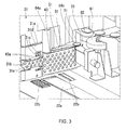
- Fig. 3 is an enlarged perspective view of the feeding section and a periphery thereof
- Fig. 4 is a perspective view showing a state in which sheets are arranged in the feeding section.
- the feeding section 2 of the sheet takeout and separation device 10 is provided with a flat bottom wall 21a, and a guide wall 21b which is provided so as to rise approximately vertically from the bottom wall 21a.
- the feeding section 2 holds a plurality of stacked sheets which are loaded on the bottom wall 21a in an upright position in a feeding direction A toward the takeout and separation section 3.
- the guide wall 21b comes in contact with respective end portions of the plurality of sheets moving in the feeding direction A, to guide the movement of the plurality of sheets.
- the feeding section 2 is further provided with a main belt 22a and sub belts 22b provided on the bottom wall 21a, and a backup plate 23 which moves on the bottom wall 21a in the feeding direction A.
- the main belt 22a and the sub belts 22b come in contact with respective end portions of the plurality of sheets loaded on the bottom wall 21a, and are independently driven in the feeding direction A.
- the main belt 22 moves the plurality of sheets loaded on the bottom wall 21a in the feeding direction A, and the sub belts 22b adjust a posture of each of the plurality of sheets.
- the backup plate 23 comes in contact with a rearmost sheet in the feeding direction A, out of the plurality of sheets arranged on the bottom wall 21a, presses the plurality of sheets in the feeding direction A, and moves in synchronization with the driving of the main belt 22a. By this means, the backup plate 23 moves the plurality of sheets loaded on the bottom wall 21a in the feeding direction A.
- the bottom wall 21a of the feeding section 2 forms a horizontal plane
- the guide wall 21b forms a vertical plane orthogonal to the horizontal plane.
- a side in the short direction is made approximately in parallel with the vertical direction.
- Each sheet is supported by the surface of the bottom wall 21a forming the horizontal plane, at lower side end portions in the vertical direction, out of the both end portions of sides in the short direction.
- Each sheet is arranged such that a side in the long direction is made in parallel with the horizontal direction, and end portions in a sending direction B side of the takeout and separation section 3 described later, out of the both end portions of sides in the long direction, are butted against the guide wall 21b.
- the plurality of sheets are arranged in the feeding section 2 such that, regarding each sheet, the end portions of the side in the short direction at the lower side in the vertical direction are aligned by the bottom walls 21a, and the end portions of the side in the long direction at the sending direction B side (that is, a forefront portion in the sending direction B) are aligned by the guide walls 21b.
- the takeout and separation section 3 is provided with a sub takeout portion 31, a main takeout portion 32, a separation portion 33.
- the sub takeout portion 31 is arranged at a more upstream side than the main takeout portion 32 in the sending direction B that is in parallel with the horizontal direction.
- the sub takeout portion 31 is provided with a sub air chamber 31a connected to a negative pressure generator (Not shown. a suction side of a blower or the like, for example), and a suction belt 31b driven by a drive motor (Not shown. a step motor or the like, for example).
- the sub air chamber 31a is provided with a sub guide plate 31d formed with a plurality of openings 31c which are opened toward the feeding section 2.
- the sub guide plate 31d is of a rectangular plate shape, and the plurality of openings 31c are communicated with the inside of the sub air chamber 31a.
- a negative pressure (a pressure lower than the atmospheric pressure) is given to the openings 31c of the sub guide plate 31d.
- the sub guide plate 31d guides the movement of the suction belt 31 to the sending direction B.
- the suction belt 31b is an endless belt formed with a plurality of suction holes 31e, and is arranged such that at least a part of the region thereof overlaps with a part of the sub guide plate 31d.
- a plurality of the suction holes 31e of the suction belt 31b communicate with at least a part of the plurality of openings 31c of the sub guide plate 31d.
- the suction belt 31b faces the plurality of sheets held in the feeding section 2 in the feeding direction A, and the suction belt 31b moves in the sending direction B, in a state that the suction belt 31b is arranged so as to extend in parallel with the sending direction B.
- the suction belt 31b takes out, by suction, a front sheet in the feeding direction A from the plurality of sheets fed by the feeding section 2.
- the suction belt 31b sends out the sheet taken out by suction, to the sending direction B at a prescribed speed.
- the prescribed speed of the suction belt 31b is set slower than a speed of a takeout belt 43 described later.
- the sub takeout portion 31 takes out a first sheet from the feeding section 2 by suction, and sends out the first sheet to the main takeout portion 32, and in addition, takes out a second sheet by suction, after the back end of the first sheet has passed through the sub air chamber 31a.
- the suction belt 31b sends out the second sheet to the main takeout portion 32 at a speed slower than the speed at which the first sheet is sent out to the sending direction B by the main takeout portion 32.
- an interval not less than a prescribed interval value is provided between the first sheet and the second sheet in the sending direction B, to resolve the overlapping of the first sheet and the second sheet.
- the main takeout portion 32 is arranged at a more downstream side than the sub takeout portion 31 in the sending direction B.
- the main takeout portion 32 is provided with a valve device 42, the takeout belt 43 which is driven by a drive motor (Not shown. a step motor or the like, for example).
- the valve device 42 is provided with a main body block 51 formed with a main guide plate 61 on one surface thereof.
- the main guide plate 61 is arranged so as to face the plurality of sheets held in the feeding section 2 in the feeding direction A.
- the main guide plate 61 guides the movement of the takeout belt 43 to the sending direction B.
- a plurality of through holes which communicate with each other is formed. These through holes are connected to a vacuum pump (not shown) provided in the valve device 42. By this means, a negative pressure is given to the through holes of the main body block 51 and the main guide plate 61.
- the takeout belt 43 is an endless belt in which a plurality of suction holes 43a is uniformly formed over the entire region thereof.
- the takeout belt 43 is wound around a plurality of pulleys (not shown) including two pulleys 64a, 64b which are respectively arranged at the both sides of the valve device 42 in the sending direction B.
- the takeout belt 43 is arranged so that at least a part of the region of the takeout belt 43 overlaps with the main guide plate 61.
- the plurality of suction holes 43a of the takeout belt 43 communicate with the through holes (not shown) formed in the main guide plate 61, at the region of the takeout belt 43 where it overlaps with the main guide plate 61. By this means, a negative pressure is given to a plurality of the suction holes 43a of the takeout belt 43.
- the takeout belt 43 moves in the sending direction B, in the state that the region of the takeout belt 43 where it overlaps with the main guide plate 61 extends in parallel with the sending direction B.
- the takeout belt 43 takes out a sheet by suction which is fed in the feeding direction A by the feeding section 2, and is sent out to the sending direction B by the sub takeout portion 31.
- the takeout belt 43 sends out the sheet taken out by suction to the sending direction B, at a speed higher than the sending speed by the sub takeout portion 31.
- the guide wall 21b of the feeding section 2 guides the sending of a sheet to the sending direction B by the takeout belt 43.
- the separation portion 33 is arranged at an opposite side of the main takeout portion 32, with respect to a sheet sent out in the sending direction B by the main takeout portion 32, at a more downstream side than the guide wall 21b of the feeding section 2 in the sending direction B.
- the separation portion 33 is provided with a double-sheet takeout preventing block 71.
- the double-sheet takeout preventing block 71 is arranged so that the double-sheet takeout preventing block 71 may face the takeout belt 43 through a gap S therebetween, at a downstream side of the takeout belt 43 in the sending direction B.
- the gap S is set to about 0.5 mm, for example.
- Fig. 5 is a perspective view of the double-sheet takeout preventing block.
- Fig. 6 is a side view of the double-sheet takeout preventing block.
- the double-sheet takeout preventing block 71 sucks a sheet at the double-sheet takeout preventing block 71 side to stop the relevant sheet, and thereby the double-sheet takeout preventing block 71 functions not to send a plurality of sheets into the gap correction portion 7 simultaneously.
- the double-side takeout preventing block 71 has a main body portion 72 formed of elastic material such as urethane rubber (rubber material), for example.
- the main body portion 72 is formed of elastic material, and thereby the main body portion 72 can be lightened, and also it is possible to shorten a time for the main body portion 72 to return to the original shape, after the main body portion 72 has been deformed by the entering of a sheet.
- An arc surface 72a is formed on the main body portion 72, at the takeout belt 43 side (tip side), and also at the entering side (an upstream side in the sending direction B) of a sheet.
- a plurality of (6, for example) suction holes 73 is formed at a position closest to the takeout belt 43, out of the arc surface 72a, that is, at a tip of the arc surface 72a. These suction holes 73 are arranged along a direction orthogonal to the sending direction B with equal intervals. Each suction hole 73 is connected to a negative pressure generator (Not shown. a vacuum pump or the like, for example) provided in the separation portion 33. By this means, a negative pressure is given to each suction hole 73.
- a base plate 74 for fixing the main body portion 72 to the sheet takeout and separation device 10 is provided.
- a support plate 75 is formed so as to cover the arc surface 72a and the side surface 72b.
- the base plate 74 and the support plate 75 are respectively fixed to the main body portion 72 using bonding agent or the like.
- a base end side of the support plate 75 is fixed to the base plate 74 via a fixing plate 76 and bolts 77.
- the support plate 75 has a role to prevent that the main body portion 72 is torn off from the base plate 74 due to the shock when a sheet enters, and a role for supporting that the main body portion 72 returns to the original shape after the main body portion 72 has been deformed.
- stainless-steel is preferable for the material of the support plate 75. Stainless-steel is used, and thereby elasticity and rust prevention of the support plate 75 can be ensured.
- a wall thickness of the support plate 75 is set to about 0.1 mm, for example, so that the support plate 75 does not affect the deformation of the main body portion 72 as far as possible.
- a protection cover 78 is provided on the surface of the support plate 75, at a position corresponding to the arc surface 72a of the main body portion 72.
- the protection cover 78 prevents the deterioration, abrasion of the main body portion 72 and the support plate 75 due to the shock when a sheet enters.
- the protection cover 78 is formed of a metal plate such as a stainless-steel plate, for example.
- a wall thickness of the protection cover 78 is set to about 1 mm, for example. With the configuration like this, the protection cover 78 can follow the deformation of the main body portion 72.
- suction holes 79 are respectively formed at the positions corresponding to the suction holes 73 of the main body portion 72. By this means, a negative pressure is given to the suction holes 79 of the protection cover 78 via the suction holes 73 of the main body portion 72.
- a surface roughening treatment M for increasing a friction coefficient of the surface of the protection cover 78 is performed on the protection cover 78, at a periphery of the suction holes 79.
- the surface roughening treatment M diamond coating, sand blast, spraying and so on can be cited.
- the surface roughening treatment M is performed so that a friction coefficient ⁇ of a place where the surface roughening treatment M is performed becomes about 0.3 - 0.5.
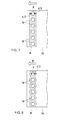
- to perform the surface roughening treatment M to the periphery of the suction holes 79 means to perform the surface roughening treatment M to the surface within a range separated by each d/2 along the sending direction B from the rims of the suction holes 739, when it is assumed that a diameter of the suction hole 79 is d, as shown in Fig. 7 , for example.
- the surface roughening treatment M may be performed on the surface within a range of a diameter of about 2d, with respect to the diameter d of the suction hole 79, coaxially with the suction holes 79.
- the gap correction section 7 along with a plurality of various conveying belts and rollers (not shown), compose a part of a conveying mechanism 80 to convey a sheet.
- the gap correction section 7 is arranged at the downstream side of the separation portion 33 in the sending direction B.
- the gap correction section 7 is provided with a sponge roller 81 and a drive roller 82 which are arranged opposite to each other so as to sandwich the main conveying path 4 therebetween.
- the sponge roller 81 is a soft roller having elasticity, and deforms in accordance with the change in a thickness of a sheet to be conveyed through the main conveying path 4.
- the drive roller 82 is rotationally driven by a drive motor (Not shown. an AC servo motor or the like, for example), and changes a conveying speed of a sheet by the acceleration and deceleration of the rotation.
- a drive motor (Not shown. an AC servo motor or the like, for example)
- the gap correction section 7 decelerates the conveying speed of the sheet, to broaden the interval.
- the gap correction section 7 accelerates the conveying speed of the sheet, to shorten the interval.
- Fig. 9 is an explanation diagram showing a behavior of the double-sheet takeout preventing block when a sheet passes through the separation portion.
- Fig. 10A, Fig. 10B and Fig. 10C are explanation diagrams of an action of the separation portion, and each shows a behavior of a sheet passing through the separation portion.
- a front sheet (a sheet located closest to the sub takeout portion 31 side), out of a plurality of sheets stacked along the feeding direction A, is sucked and taken out by the sub takeout portion 31, and the taken-out sheets are sent out to the main takeout portion 32 one by one.
- a sheet which has been sent out to the main takeout portion 32 passes through the gap S (refer to Fig. 6 ) between the double-sheet takeout preventing block 71 of the separation portion 33 and the takeout belt 43 of the main takeout portion 32, and is sent out to the gap correction section 7.
- a thickness of a sheet is equivalent to, or thinner than the gap S between the double-sheet takeout preventing block 71 and the takeout belt 43, the sheet passes through the gap S, without change.
- a radius of curvature of the arc surface 72a formed on the main body portion 72 of the double-sheet takeout preventing block 71 is R
- a wall thickness of the protection cover 78 is t
- a maximum thickness of a sheet is Hmax
- the gap between the double-sheet takeout preventing block 71 and the takeout belt 43 is S
- the radius of curvature R is set so as to satisfy R ⁇ Hmax - S x 2 - t
- a size of the main body portion 72 in the length direction (a vertical direction in Fig. 6 ) is not less than about 5 times the maximum deformation amount (Hmax - S) of the main body portion 72.
- the surface roughening treatment M is performed on the protection cover 78 only at the periphery of the suction holes 79 (refer to Fig. 5 ), when the double-sheet takeout preventing block 71 is compressed and deformed so that it is slightly bent backward toward the downstream side in the sending direction B, the place where the surface roughening treatment M is performed faces toward the downstream side in the sending direction B. For this reason, when a thick sheet comes in contact with the protection cover 78, the sheet comes to make contact with the place of the protection cover 78 where the surface roughening treatment is not performed, and thereby the friction between the protection cover 78 and the sheet does not increase. Accordingly, the sheet can smoothly pass through between the double-sheet takeout preventing block 71 and the takeout belt 43.
- the surface roughening treatment M is performed on the protection cover 78 of the double-sheet takeout preventing block 71, at the periphery of the suction holes 79 (refer to Fig. 5 ). For this reason, a friction force between the periphery of the suction holes 79 and the sheet sucked by the suction holes 79 becomes large. Accordingly, it is possible to surely stop one of the sheets in an overlapping state, by the double-sheet takeout preventing block 71, while weakening the suction force (negative pressure) of the double-sheet takeout preventing block 71.
- the plurality of suction holes 79 provided in the protection cover 78 are arranged along a direction orthogonal to the sending direction B with equal intervals (refer to Fig. 5 ). For this reason, it is possible to prevent that the sheet sucked by the double-sheet takeout preventing block 71 might be rotated (skew) around one point.
- a suction force of the valve device 42 of the main takeout portion 32 against a sheet is set sufficiently larger than a suction force of the separation portion 33 against a sheet. For this reason, when the sheet at the takeout belt 43 side has completely passed through the double-sheet takeout preventing block 71, the sheet which has been stopped by the double-sheet takeout preventing block 71 is surely sucked to the takeout belt 43 side.
- the sheet at the double-sheet takeout preventing block 71 side comes to stop in front thereof, without reaching the suction holes 79 of the protection cover 78. That is, a force by which the sheet at the double-sheet takeout preventing block 71 side tries to press the double-sheet takeout preventing block 71 away acts on as a resistance force, and thereby the sheet stops, and during this time, the sheet at the takeout belt 43 side is sent out to the gap correction section 7. For the reason, sheets still in an overlapping state can be surely separated by the separation portion 33, regardless of the thicknesses of the sheets.
- a prescribed speed of the suction belt 31b in the sub takeout portion 31 is set slower than a speed of the takeout belt 43 in the main takeout portion 32. For this reason, an interval not less than a prescribed interval is provided between a sheet (first sheet) which has firstly been sent out from the feeding section 2, and a sheet (second sheet) which has been sent out next, and thereby the overlapping of the first sheet and the second sheet can be resolved. Accordingly, it is possible to prevent that the sheet which has been stopped by the double-sheet takeout preventing block 71 might overlap again with a sheet located in a more upstream side than this sheet in the sending direction B.
- the surface roughening treatment M is performed on the protection cover 78 provided on the main body portion 72. For this reason, when sheets still in an overlapping state are conveyed by the takeout belt 43, it is possible to surely stop a sheet at the double-sheet takeout preventing block 71 side, using a friction force of a place where the surface roughening treatment M is performed. Accordingly, it is possible to prevent that a plurality of sheets is sent out in an overlapping manner, and the occurrence of conveying trouble can be prevented.
- the sheet takeout and separation device 10 (a negative pressure generator and so on provided in the separation portion 33) can be miniaturized.
- the main body portion 72 is formed of elastic material which elastically deforms in accordance with the thickness of a sheet, and further the surface roughening treatment M is performed on the protection cover 78 at the periphery of the suction holes 79. For this reason, overlapping sheets can be efficiently stopped by the suction holes 79, and in addition, it is possible to prevent that a thick sheet or the like might be damaged by a place where the surface roughening treatment M is performed.
- the protection cover 78 of the double-sheet takeout preventing block 71 is of a metal plate (stainless-steel plate, for example). For this reason, it is possible to set a friction coefficient of a place where the surface roughening treatment M is not performed low, while keeping the stiffness of the protection cover 78 itself. Accordingly, when sheets do not overlap and the sheets are conveyed one by one, the sheets can smoothly pass through on the double-sheet takeout preventing block 71.
- a plurality of the suction holes 79 of the protection cover 78 is formed with equal intervals along a direction orthogonal to the sending direction B. For this reason, the suction holes 79 can prevent that a sheet sucked by the double-sheet takeout preventing block 71 is rotated (skew) around one point. That is, when a sheet is stopped at one point, there is a possibility that the sheet might be skewed around that point. But a sheet is stopped at at least two or more points, and thereby it can be prevented that a sheet might be skewed.
- the double-sheet takeout preventing block 71 is arranged opposite to the takeout belt 43 through the gap S, at the downstream side of the sending direction B in the takeout belt 43. For this reason, when sheets still in an overlapping state are conveyed by the takeout belt 43, while one sheet out of these sheets is stopped by the double-sheet takeout preventing block 71, the other sheet can surely be sent out to the gap correction section 7 by the takeout belt 43.
- the arc surface 72a is formed at the takeout belt 43 side (tip side), and also at the entering side of a sheet (upstream side in the sending direction B). For this reason, the double-sheet takeout preventing block 71 can smoothly receive a sheet.
- the radius of curvature R of the arc surface 72a is set so as to satisfy the expression (1). For this reason, when the main body portion 72 is pressed by a sheet, it is possible to set a direction of the force acting on the main body portion 72 by this pressing force, to a direction to which the main body portion 72 is surely compressed.
- the surface roughening treatment M is performed only to the periphery of the suction holes 79 in the protection cover 78 of the double-sheet takeout preventing block 71.
- the surface roughening treatment M may be performed to the whole surface of the protection cover 78.
- the surface roughening treatment M may be performed to only about a half of the whole surface of the protection cover 78 including the periphery of the suction holes 79. In this case, it is necessary to set a friction coefficient by the surface roughening treatment M, so that the surface roughening treatment M does not damage a sheet.
- the surface roughening treatment M is performed to the protection cover 78, by diamond coating, sand blast, spraying, and so on, for example.
- the surface roughening treatment M is not limited to this, a tape, a rubber sheet, or the like for enhancing the friction resistance may be pasted on the surface of the protection cover 78. In this case, it is desirable to perform a replacing operation of a tape or a rubber sheet, in accordance with the using frequency of the sheet processing apparatus 1.
- the protection cover 78 is formed of a stainless-steel plate, for example.
- the protection cover 78 is not limited to this, the material of the protection cover 78 may be material, if a friction coefficient at the surface of the material is low.
- the material may be engineering plastics of which abrasion resistance was examined.
- the sheet takeout and separation device and the sheet processing apparatus as described above, since the surface roughening treatment M is performed on the protection cover 78 of the double-sheet takeout preventing block 71, it is possible to surely prevent that a plurality of sheets are sent out in an overlapping manner, and the occurrence of conveying trouble can be prevented. In addition, since it is possible to prevent that a plurality of sheets are sent out in an overlapping manner, while weakening the suction force of the separation portion 33 as much as possible, the sheet takeout and separation device 10 (a negative pressure generator and so on provided in the separation portion 33) can be miniaturized.
Landscapes
- Engineering & Computer Science (AREA)
- Mechanical Engineering (AREA)
- Sheets, Magazines, And Separation Thereof (AREA)
Applications Claiming Priority (1)
| Application Number | Priority Date | Filing Date | Title |
|---|---|---|---|
| JP2014168481A JP2016044023A (ja) | 2014-08-21 | 2014-08-21 | 紙葉類取出分離装置および紙葉類処理装置 |
Publications (1)
| Publication Number | Publication Date |
|---|---|
| EP2987752A1 true EP2987752A1 (de) | 2016-02-24 |
Family
ID=53886917
Family Applications (1)
| Application Number | Title | Priority Date | Filing Date |
|---|---|---|---|
| EP15180940.7A Withdrawn EP2987752A1 (de) | 2014-08-21 | 2015-08-13 | Folienherausnahme- und trennvorrichtung und bogenverarbeitungsvorrichtung |
Country Status (5)
| Country | Link |
|---|---|
| US (2) | US20160052734A1 (de) |
| EP (1) | EP2987752A1 (de) |
| JP (1) | JP2016044023A (de) |
| CN (1) | CN105383966A (de) |
| RU (1) | RU2613223C2 (de) |
Families Citing this family (3)
| Publication number | Priority date | Publication date | Assignee | Title |
|---|---|---|---|---|
| JP6941870B2 (ja) | 2018-01-26 | 2021-09-29 | ローレル精機株式会社 | 紙葉類処理装置 |
| CN108861702A (zh) * | 2018-06-01 | 2018-11-23 | 三峡大学 | 一种粽叶s型上料装置 |
| JP2023111725A (ja) * | 2022-01-31 | 2023-08-10 | Pacraft株式会社 | 袋搬送システム |
Citations (4)
| Publication number | Priority date | Publication date | Assignee | Title |
|---|---|---|---|---|
| US5725209A (en) * | 1994-09-30 | 1998-03-10 | Canon Kabushiki Kaisha | Sheet supply apparatus |
| US5888047A (en) * | 1996-12-30 | 1999-03-30 | Pitney Bowes Inc. | Separating and feeding machine for bound booklets |
| WO2009118927A1 (en) * | 2008-03-25 | 2009-10-01 | Kabushiki Kaisha Toshiba | Sheet processing apparatus |
| EP2639190A2 (de) * | 2012-03-16 | 2013-09-18 | Kabushiki Kaisha Toshiba | Vorrichtung zur Blatthandhabung |
Family Cites Families (16)
| Publication number | Priority date | Publication date | Assignee | Title |
|---|---|---|---|---|
| US3219339A (en) * | 1962-07-25 | 1965-11-23 | Fmc Corp | Article separating apparatus |
| DE1904705A1 (de) * | 1969-01-31 | 1970-08-06 | Licentia Gmbh | Saugbandvereinzeler fuer flache Sendungen |
| US3861669A (en) * | 1972-06-15 | 1975-01-21 | Tokyo Shibaura Electric Co | Apparatus for feeding sheet-like articles from a stack of articles |
| DE2309756A1 (de) * | 1973-02-27 | 1974-09-12 | Licentia Gmbh | Einrichtung zur abgabe von einzelnen briefen und aehnlichen flachen sendungen aus einem stapel |
| US4357007A (en) * | 1980-04-24 | 1982-11-02 | International Standard Electric Corporation | Singler device |
| SU1708698A1 (ru) * | 1989-09-05 | 1992-01-30 | Московская Печатная Фабрика Гознака | Устройство дл отделени листов от стопы и подачи их к обрабатывающей машине |
| IT1257776B (it) * | 1992-03-26 | 1996-02-13 | Gd Spa | Dispositivo di alimentazione di sbozzati ad una macchina utilizzatrice |
| US6511062B1 (en) * | 2000-02-07 | 2003-01-28 | Lockheed Martin Corporation | Presentation control for flat article singulation mechanism and sensors suitable for use therewith |
| JP4550257B2 (ja) * | 2000-11-24 | 2010-09-22 | 株式会社東芝 | 紙葉類取出装置 |
| US6651974B2 (en) * | 2001-02-23 | 2003-11-25 | Canon Kabushiki Kaisha | Sheet feed apparatus and recording apparatus equipped with sheet feed apparatus |
| DE10314694A1 (de) * | 2003-03-28 | 2004-10-21 | Mathias Bäuerle GmbH | Zuführeinrichtung für Stapel aus Papier, Kunststoff und dergleichen |
| US7303188B2 (en) * | 2003-11-06 | 2007-12-04 | James Malatesta | Document separator |
| JP4158040B2 (ja) * | 2004-04-28 | 2008-10-01 | ブラザー工業株式会社 | 被記録媒体給送装置及びそれを備えた画像記録装置 |
| JP4748723B2 (ja) * | 2006-05-31 | 2011-08-17 | リコーエレメックス株式会社 | シート送りローラ装置および画像形成装置 |
| JP4302148B2 (ja) * | 2007-03-12 | 2009-07-22 | 株式会社東芝 | 紙葉類分離装置,紙葉類分離取り出し装置,紙葉類処理装置,紙葉類分離方法,そして紙葉類分離取り出し方法 |
| JP2008247605A (ja) * | 2007-03-30 | 2008-10-16 | Toshiba Corp | 紙葉類取出装置 |
-
2014
- 2014-08-21 JP JP2014168481A patent/JP2016044023A/ja active Pending
-
2015
- 2015-08-13 EP EP15180940.7A patent/EP2987752A1/de not_active Withdrawn
- 2015-08-19 US US14/830,461 patent/US20160052734A1/en not_active Abandoned
- 2015-08-20 RU RU2015135386A patent/RU2613223C2/ru active
- 2015-08-21 CN CN201510520986.XA patent/CN105383966A/zh active Pending
-
2017
- 2017-05-17 US US15/598,012 patent/US20170253446A1/en not_active Abandoned
Patent Citations (4)
| Publication number | Priority date | Publication date | Assignee | Title |
|---|---|---|---|---|
| US5725209A (en) * | 1994-09-30 | 1998-03-10 | Canon Kabushiki Kaisha | Sheet supply apparatus |
| US5888047A (en) * | 1996-12-30 | 1999-03-30 | Pitney Bowes Inc. | Separating and feeding machine for bound booklets |
| WO2009118927A1 (en) * | 2008-03-25 | 2009-10-01 | Kabushiki Kaisha Toshiba | Sheet processing apparatus |
| EP2639190A2 (de) * | 2012-03-16 | 2013-09-18 | Kabushiki Kaisha Toshiba | Vorrichtung zur Blatthandhabung |
Also Published As
| Publication number | Publication date |
|---|---|
| US20170253446A1 (en) | 2017-09-07 |
| CN105383966A (zh) | 2016-03-09 |
| RU2015135386A (ru) | 2017-02-27 |
| US20160052734A1 (en) | 2016-02-25 |
| RU2613223C2 (ru) | 2017-03-15 |
| JP2016044023A (ja) | 2016-04-04 |
Similar Documents
| Publication | Publication Date | Title |
|---|---|---|
| JP5778760B2 (ja) | 可動カバー内に1つ以上の物品を挿入する装置および方法 | |
| JP6242996B2 (ja) | 紙葉類処理装置 | |
| US20170253446A1 (en) | Sheet takeout and separation device and sheet processing apparatus | |
| US20120013065A1 (en) | Device for separating flat articles, a corresponding control method, and a corresponding postal machine | |
| US7222846B2 (en) | Sheet take-out apparatus and method of taking out sheets | |
| EP2781478A2 (de) | Vorrichtung zum Aufnehmen von Papierbogen und Vorrichtung zur Verarbeitung von Papierbogen | |
| JP2011190022A (ja) | 給紙装置 | |
| KR20190005723A (ko) | 시트 회수 디바이스 및 시트 반송 회수 시스템 그리고 시트 회수 방법 | |
| EP2987753B1 (de) | Bogenentnahmevorrichtung bogenverarbeitungsvorrichtung | |
| CN114148786B (zh) | 供纸装置及其控制方法以及存储有其控制程序的存储介质 | |
| CN101516751A (zh) | 裁压机供料台上片材的传送辅助驱动装置 | |
| CN114644251B (zh) | 后处理装置、记录系统 | |
| JP2000296960A (ja) | シート積上げ装置 | |
| JP4624185B2 (ja) | 紙葉類処理装置 | |
| JP4766684B2 (ja) | 用紙搬送装置 | |
| JP2000053304A (ja) | シート処理装置 | |
| JP5981624B2 (ja) | 紙葉類取り出し装置 | |
| JP2015147662A (ja) | 紙葉類取出分離装置および紙葉類処理装置 | |
| JPH07228393A (ja) | 紙葉類搬送装置 | |
| JP2018048011A (ja) | シート集積装置およびシート集積方法 | |
| JP2008143652A (ja) | 層間シート搬送装置 | |
| JP2009274861A (ja) | フィルム体搬送装置およびフィルム体加工システム | |
| JP2001322364A (ja) | 平版印刷版の集積装置及び平版印刷版束の製造方法 | |
| JP2013199376A (ja) | 紙葉類取り出し装置 | |
| JP2012136299A (ja) | 用紙整合装置 |
Legal Events
| Date | Code | Title | Description |
|---|---|---|---|
| PUAI | Public reference made under article 153(3) epc to a published international application that has entered the european phase |
Free format text: ORIGINAL CODE: 0009012 |
|
| 17P | Request for examination filed |
Effective date: 20150813 |
|
| AK | Designated contracting states |
Kind code of ref document: A1 Designated state(s): AL AT BE BG CH CY CZ DE DK EE ES FI FR GB GR HR HU IE IS IT LI LT LU LV MC MK MT NL NO PL PT RO RS SE SI SK SM TR |
|
| AX | Request for extension of the european patent |
Extension state: BA ME |
|
| STAA | Information on the status of an ep patent application or granted ep patent |
Free format text: STATUS: THE APPLICATION HAS BEEN WITHDRAWN |
|
| 18W | Application withdrawn |
Effective date: 20180405 |