EP2987664A1 - Übergang zwischen zwei gelenkig miteinander verbundenen Fahrzeugen - Google Patents
Übergang zwischen zwei gelenkig miteinander verbundenen Fahrzeugen Download PDFInfo
- Publication number
- EP2987664A1 EP2987664A1 EP14002903.4A EP14002903A EP2987664A1 EP 2987664 A1 EP2987664 A1 EP 2987664A1 EP 14002903 A EP14002903 A EP 14002903A EP 2987664 A1 EP2987664 A1 EP 2987664A1
- Authority
- EP
- European Patent Office
- Prior art keywords
- bellows
- profile
- angle
- vehicle
- transition
- Prior art date
- Legal status (The legal status is an assumption and is not a legal conclusion. Google has not performed a legal analysis and makes no representation as to the accuracy of the status listed.)
- Granted
Links
- 230000007704 transition Effects 0.000 claims abstract description 22
- 210000000078 claw Anatomy 0.000 claims description 14
- 229920001971 elastomer Polymers 0.000 claims description 12
- 239000000806 elastomer Substances 0.000 claims description 12
- 230000008719 thickening Effects 0.000 claims description 9
- 239000004744 fabric Substances 0.000 description 5
- 238000005452 bending Methods 0.000 description 1
- 238000010276 construction Methods 0.000 description 1
- 238000001514 detection method Methods 0.000 description 1
- 230000000284 resting effect Effects 0.000 description 1
- 238000005096 rolling process Methods 0.000 description 1
- 238000009958 sewing Methods 0.000 description 1
- 238000004073 vulcanization Methods 0.000 description 1
Images

Classifications
-
- B—PERFORMING OPERATIONS; TRANSPORTING
- B60—VEHICLES IN GENERAL
- B60D—VEHICLE CONNECTIONS
- B60D5/00—Gangways for coupled vehicles, e.g. of concertina type
- B60D5/003—Bellows for interconnecting vehicle parts
Definitions
- the invention relates to a transition between two articulated vehicles, wherein the transition comprises at least one tunnel-shaped circumferential bellows, wherein for connection of the bellows with the front side of the vehicle, a connecting device is provided.
- Transitions in particular between vehicles of a rail vehicle, are well known from the prior art. Such transitions usually include at least a bellows that spans a platform or bridge to allow people to transfer from one vehicle to another vehicle. Also known in this connection are so-called double-shaft bellows, that is to say two bellows which are mounted one inside the other and which in particular offer increased soundproofing. This is particularly relevant for fast moving trains, such as the ICE or the TGV. Another problem is that between the individual vehicles pitching, rolling, bending and offset movements must be allowed, as they occur, for example, when such a vehicle drives over a switch. This means that the bellows must be able to provide considerable elasticity to allow such movements. In particular, in double-shaft bellows or double bellows has been found that the connection of the bellows on the front side of the articulated vehicles connected by a corresponding connection device is very expensive.
- the object underlying the invention is to provide a connecting device for a bellows and here in particular also for a Doppelwellenbalg, which is much simpler and cheaper in construction, but is still able to safely, the bellows or the two bellows with the front page to connect the respective vehicle.
- the connecting device has a tunnel-shaped circumferential, in cross-section in approximately C-shaped recess arranged on the front side of the vehicle, wherein at least one angle profile is provided, the means for detecting the at least one at its first free end Bellows, and is connected at its second end by at least one elastomeric profile with the C-shaped recess.
- the second end of the angle profile is formed in the manner of a welt, and this second end formed in the manner of a welt is connected to the elastomer profile.
- a piping is commonly understood a bead-like thickening, which adjoins a web, wherein the receiving part, in the present case, the elastomeric profile having a corresponding opening, wherein the web with the bead-like thickening in the opening of the female part, ie the elastomer profile , either inserted or pressed.
- the bellows, and accordingly also the C-shaped recess are formed circumferentially, one will press the embossed web in the manner of a welt with the bead-like thickening in the elastomeric profile or hit.
- the elastomer profile is positively received by the C-shaped recess.
- the angle profile is advantageously characterized by the fact that it detects the bellows at its first free end by a clamp-like claw.
- a limb advantageously arranged at right angles to the web, which has the clamp-like claw at the end as a means for detecting the bellows.
- the bellows itself consists of a coated fabric or of individual bellows elements, which are assembled by sewing or vulcanization to a bellows, wherein the individual bellows elements have a fabric which is coated with an elastomer.
- the clamp-like claw of the angle profile now the last, so the edge-side bellows element is detected.
- the clamp-like claw on the inside advantageously has a toothing.
- the at least one elastomeric profile has two similar openings for receiving in each case one web with end-side bead-like thickening of two angle profiles for one bellows each.
- spacings between the waves of a double-wave bellows are to be realized which are approximately 70 to 95 mm. This opens up the possibility of a considerable passage width in the area of the transition between two articulated vehicles, so that even wheelchair users can get from one car to the next car.
- the at least one angle profile has a second means for detecting at least one further bellows.
- the leg of the angle profile as a means for detecting the at least one further bellows has a clamp-like claw.
- the second jaw is advantageously attached to the leg of the angle profile in such a way that the bellows nestle one inside the other. This has the advantage that the wall thickness of the Doppelwellenbalges can be kept very low.
- This clip-like claw can be used in a variety of ways with the Leg of the angle profile be connected, for example, it is screwed or riveted to the leg.
- the two vehicles 2 and 3 of a rail vehicle 1 are connected to each other by a joint (not shown). Between the two vehicles 2, 3, a transition 5 is provided, which includes a bellows, which surrounds a transition bridge or platform tunnel-like, as is well known from the prior art.
- Fig. 2 now shows the connection of a Doppelwellenbalges a transition 5 on the front side of a vehicle 3 in a first variant.
- the vehicle 3 on its front side on a recess 7, which is C-shaped, as this is directly in the view of Fig. 2 results.
- the C-shaped recess 7 is the elastomeric profile 9.
- the C-shaped recess 7 is formed by the housing 40, which is in communication with the vehicle 3.
- the housing 40 has two sub-housings 41, 42, which are interconnected by a flange 43, and so that in the C-shaped recess resting elastomeric profile 9 is detected by clamping.
- the elastomeric profile 9 serves to receive two angle sections 11 and 13, which are formed substantially identical except for the length of the legs and the webs.
- Each angle profile 11, 13 shows at its first free end on the legs 14, 15 subsequently, a clamp-like claw 20, 21 for receiving a coated with an elastomeric fabric web 23, 24 of the bellows 26, 28.
- the leg At the other second end, the leg a web 17, 18, the end a bead-like thickening 29, 30 shows, wherein the elastomeric profile 9 each has a corresponding opening 10 for receiving the web with the bead-like thickening.
Landscapes
- Engineering & Computer Science (AREA)
- Mechanical Engineering (AREA)
- Diaphragms And Bellows (AREA)
Abstract
Description
- Die Erfindung betriff einen Übergang zwischen zwei gelenkig miteinander verbundenen Fahrzeugen, wobei der Übergang mindestens einen tunnelförmig umlaufenden Balg umfasst, wobei zur Verbindung des Balges mit der Stirnseite des Fahrzeugs eine Verbindungseinrichtung vorgesehen ist.
- Übergänge, insbesondere zwischen Fahrzeugen eines Schienenfahrzeuges, sind aus dem Stand der Technik hinreichend bekannt. Derartige Übergänge umfassen hierbei üblicherweise mindestens einen Balg, der eine Plattform oder eine Brücke überspannt, um Personen das Hinüberwechseln von einem Fahrzeug zum anderen Fahrzeug zu ermöglichen. Bekannt sind in diesem Zusammenhang auch sogenannte Doppelwellenbälge, das heißt zwei ineinander gelagerte Bälge, die insbesondere einen erhöhten Schallschutz bieten. Dies ist insbesondere relevant bei schnell fahrenden Zügen, wie beispielsweise dem ICE oder dem TGV. Problematisch ist ebenfalls, dass zwischen den einzelnen Fahrzeugen Nick-, Wank-, Knick- und auch Versatzbewegungen zugelassen werden müssen, wie sie beispielsweise auftreten, wenn ein solches Fahrzeug über eine Weiche fährt. Das heißt, dass der Balg durchaus in der Lage sein muss eine erhebliche Dehnfähigkeit bereitzustellen, um eben solche Bewegungen zuzulassen. Insbesondere bei Doppelwellenbälgen oder auch doppelten Faltenbälgen hat sich herausgestellt, dass die Anbindung der Bälge an der Stirnseite der gelenkig miteinander verbundenen Fahrzeuge durch eine entsprechende Verbindungseinrichtung sehr aufwendig ist.
- Die der Erfindung zugrunde liegende Aufgabe besteht darin, eine Verbindungseinrichtung für einen Balg und hier insbesondere auch für einen Doppelwellenbalg bereitzustellen, die wesentlich einfacher und preiswerter im Aufbau ist, aber dennoch sicher in der Lage ist, den Balg bzw. die beiden Bälge mit der Stirnseite des jeweiligen Fahrzeugs zu verbinden.
- Zur Lösung der Aufgabe wird erfindungsgemäß vorgeschlagen, dass die Verbindungseinrichtung eine an der Stirnseite des Fahrzeugs angeordnete tunnelförmig umlaufende, im Querschnitt in etwa C-förmigen Aussparung aufweist, wobei mindestens ein Winkelprofil vorgesehen ist, das an seinem ersten freien Ende Mittel zur Erfassung des mindestens einen Balges aufweist, und an seinem zweiten Ende durch mindestens ein Elastomerprofil mit der C-förmigen Aussparung verbunden ist. Hieraus wird deutlich, dass die Verbindung des Balges mit der Stirnseite des jeweiligen Fahrzeuges im Wesentlichen durch eine Klemmverbindung mit mindestens einem Elastomerprofil bereitgestellt wird, wobei das Elastomerprofil in der C-förmigen Aussparung lagert.
- Nach einem besonderen Merkmal der Erfindung ist vorgesehen, dass das zweite Ende des Winkelprofils nach Art eines Keders ausgebildet ist, und dieses nach Art eines Keders ausgebildete zweite Ende mit dem Elastomerprofil verbunden ist. Unter einem Keder wird gemeinhin eine wulstartige Verdickung verstanden, die sich an einen Steg anschließt, wobei der aufnehmende Teil, im vorliegenden Fall das Elastomerprofil, eine entsprechende Öffnung aufweist, wobei der Steg mit der wulstartigen Verdickung in die Öffnung des aufnehmenden Teils, also des Elastomerprofils, entweder eingeschoben oder eingepresst wird. Da im vorliegenden Fall der Balg, und entsprechend auch die C-förmige Aussparung umlaufend ausgebildet sind, wird man den nach Art eines Keders ausgebildeten Steg mit der wulstartigen Verdickung in das Elastomerprofil einpressen bzw. einschlagen.
- Um zu verhindern, dass das Elastomerprofil aus der C-förmigen Aussparung herausgelangen kann, ist vorgesehen, dass das Elastomerprofil formschlüssig durch die C-förmige Aussparung aufgenommen wird.
- Weiterhin zeichnet sich das Winkelprofil vorteilhaft dadurch aus, dass es an seinem ersten freien Ende den Balg durch eine klammerartige Klaue erfasst. Hierzu ist an dem Steg ein Schenkel, vorteilhaft im rechten Winkel zu dem Steg angeordnet, der endseitig die klammerartige Klaue als Mittel zur Erfassung des Balges aufweist. Der Balg selbst besteht aus einem beschichteten Gewebe bzw. aus einzelnen Balgelementen, die durch Nähen oder Vulkanisieren zu einem Balg zusammengesetzt sind, wobei die einzelnen Balgelemente ein Gewebe aufweisen, das mit einem Elastomer beschichtet ist. Durch die klammerartige Klaue des Winkelprofils wird nun das letzte, also das randseitige Balgelement erfasst. Zur sicheren Erfassung des Balges weist die klammerartige Klaue auf der Innenseite vorteilhaft eine Verzahnung auf.
- Nach einer besonderen Variante ist vorgesehen, dass das mindestens eine Elastomerprofil zwei gleichartige Öffnungen zur Aufnahme jeweils eines Steges mit endseitiger wulstartiger Verdickung von zwei Winkelprofilen für jeweils einen Balg aufweist. Hierdurch wird die Möglichkeit eröffnet, zwei Bälge relativ nah beieinander durch eine C-förmige Aussparung mit mindestens einem in der C-förmigen Aussparung gelagerten Elastomerprofil aufzunehmen. Das heißt, es sind hierbei Abstände zwischen den Wellen eines Doppelwellenbalges zu verwirklichen, die bei etwa 70 bis 95 mm liegen. Dies eröffnet die Möglichkeit einer erheblichen Durchgangsweite im Bereich des Übergangs zwischen zwei gelenkig miteinander verbundener Fahrzeuge, sodass auch Rollstuhlfahrer von einem Waggon in den nächsten Waggon gelangen können.
- Eine weitere Variante, die noch platzsparender ist, zeichnet sich dadurch aus, dass das mindestens eine Winkelprofil ein zweites Mittel zur Erfassung mindestens eines weiteren Balges aufweist. Das heißt, dass durch ein einziges Winkelprofil zwei Bälge erfasst werden, was die Wandstärke eines solchen Doppelwellenbalges noch weiterhin vermindert. Im Einzelnen ist in diesem Zusammenhang vorgesehen, dass der Schenkel des Winkelprofiles als Mittel zur Erfassung des mindestens einen weiteren Balges eine klammerartige Klaue aufweist. Hierbei ist die zweite Klaue vorteilhaft derart an dem Schenkel des Winkelprofils angebracht, dass die Bälge verschachtelt ineinander lagern. Dies hat den Vorteil, dass die Wandstärke des Doppelwellenbalges sehr gering gehalten werden kann. Diese klammerartige Klaue kann auf verschiedenste Art und Weise mit dem Schenkel des Winkelprofils verbunden sein, beispielsweise ist sie mit dem Schenkel verschraubt oder vernietet.
- Anhand der Zeichnungen wird die Erfindung nachstehend beispielhaft näher erläutert.
- Fig. 1
- zeigt schematisch einen Übergang zwischen zwei gelenkig miteinander verbundenen Fahrzeugen;
- Fig. 2
- zeigt schematisch die Anbindung eines Doppelwellenbalges an der Stirnseite eines Fahrzeugs als erste Variante;
- Fig. 3
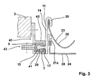
- zeigt schematisch die Anbindung des Doppelwellenbalges an der Stirnseite eines Fahrzeugs als zweite Variante.
- Die beiden Fahrzeuge 2 und 3 eines Schienenfahrzeugs 1 sind durch ein Gelenk (nicht dargestellt) miteinander verbunden. Zwischen den beiden Fahrzeugen 2, 3 ist ein Übergang 5 vorgesehen, der einen Balg umfasst, der eine Übergangsbrücke oder Plattform tunnelartig umspannt, wie dies aus dem Stand der Technik hinreichend bekannt ist.
-
Fig. 2 zeigt nun die Anbindung eines Doppelwellenbalges eines Übergangs 5 an der Stirnseite eines Fahrzeuges 3 in einer ersten Variante. Hierbei weist das Fahrzeug 3 an seiner Stirnseite eine Aussparung 7 auf, die C-förmig ausgebildet ist, wie sich dies unmittelbar in Anschauung vonFig. 2 ergibt. In der C-förmigen Aussparung 7 befindet sich das Elastomerprofil 9. Die C-förmige Aussparung 7 wird gebildet durch das Gehäuse 40, das mit dem Fahrzeug 3 in Verbindung steht. Das Gehäuse 40 besitzt zwei Teilgehäuse 41, 42, die durch einen Flansch 43 miteinander verbunden sind, und so dass in der C-förmigen Aussparung ruhende Elastomerprofil 9 klemmend erfasst ist. - Das Elastomerprofil 9 dient der Aufnahme zweier Winkelprofile 11 und 13, die bis auf die Länge der Schenkel und der Stege im Wesentlichen identisch ausgebildet sind. Jedes Winkelprofil 11, 13 zeigt an seinem ersten freien Ende an den Schenkeln 14, 15 anschließend, eine klammerartige Klaue 20, 21 zur Aufnahme einer mit einem Elastomer beschichten Gewebebahn 23, 24 des Balges 26, 28. An dem anderen zweiten Ende weist der Schenkel einen Steg 17, 18 auf, der endseitig eine wulstartige Verdickung 29, 30 zeigt, wobei das Elastomerprofil 9 jeweils eine entsprechende Öffnung 10 zur Aufnahme des Steges mit der wulstartigen Verdickung besitzt. Durch das Einschlagen der beiden Stege 17, 18 des Winkelprofils 11, 13 in das Elastomerprofil 9 wird das Elastomerprofil 9 gespreizt, sodass es sicher in der C-förmigen Aussparung 7 einsitzt.
- Die Variante gemäß
Fig. 3 - gleichartige Teile sind hierbei mit den entsprechenden Bezugszeichen ausFig. 2 versehen worden - unterscheidet sich von der gemäßFig. 2 ausschließlich dadurch, dass hier das Winkelprofil 11 an seinem Schenkel 14 eine weitere Klaue 21 a zur Aufnahme eines zweiten Balges 28 aufweist. Dadurch, dass die weitere Klaue 21 a an dem Schenkel 14 des Winkelprofiles 11 angebracht ist, besteht die Möglichkeit, die beiden Bälge 26 und 28 noch weiter ineinander zu verschachteln, dass heißt noch platzsparender zu bauen, was schlussendlich zu einem noch geringeren Abstand der Wellen eines Doppelwellenbalges führt. -
- 1
- Schienenfahrzeug
- 2
- Fahrzeug
- 3
- Fahrzeug
- 5
- Übergang
- 7
- C-förmige Aussparung
- 9
- Elastomerprofil
- 10
- Öffnung
- 11
- Winkelprofil
- 13
- Winkelprofil
- 14
- Schenkel
- 15
- Schenkel
- 17
- Steg
- 18
- Steg
- 20
- klammerartige Klaue
- 21
- klammerartige Klaue
- 21a
- klammerartige Klaue
- 23
- Gewebebahn
- 24
- Gewebebahn
- 26
- Balg
- 28
- Balg
- 29
- wulstartige Verdickung
- 30
- wulstartige Verdickung
- 40
- Gehäuse
- 41
- Teilgehäuse
- 42
- Teilgehäuse
- 43
- Flansch
Claims (10)
- Übergang (5) zwischen zwei gelenkig miteinander verbundenen Fahrzeugen (2, 3), wobei der Übergang (5) mindestens einen tunnelförmig umlaufenden Balg (26, 28) umfasst, wobei zur Verbindung des Balges (26, 28) mit der Stirnseite eines Fahrzeugs (2, 3) eine Verbindungseinrichtung vorgesehen ist,
dadurch gekennzeichnet,
dass die Verbindungseinrichtung eine an der Stirnseite des Fahrzeugs (2, 3) angeordnete tunnelartige umlaufende, im Querschnitt in etwa C-förmige Aussparung (7) aufweist, wobei mindestens ein Winkelprofil (11, 13) vorgesehen ist, das an seinem ersten freien Ende Mittel zur Erfassung des mindestens einen Balges (26, 28) aufweist und an seinem zweiten Ende durch mindestens ein Elastomerprofil (9) mit der C-förmigen Aussparung (7) verbunden ist. - Übergang nach Anspruch 1,
dadurch gekennzeichnet,
dass das zweite Ende des Winkelprofils (11, 13) nach Art eines Keders ausgebildet ist, und mit dem Elastomerprofil (9) verbunden ist. - Übergang nach einem der voranstehenden Ansprüche,
dadurch gekennzeichnet,
dass das Elastomerprofil (9) formschlüssig in der C-förmigen Aussparung (7) des Fahrzeugs (2, 3) einliegt. - Übergang nach einem der voranstehenden Ansprüche,
dadurch gekennzeichnet,
dass das Winkelprofil (11, 13) an seinem zweiten Ende einen Steg (17, 18) aufweist, an den sich winklig dazu ein Schenkel (14, 15) mit der klammerartigen Klaue (20, 21) für den Balg anschließt. - Übergang nach Anspruch 1,
dadurch gekennzeichnet,
dass der Steg (17, 18) eine wulstartige Verdickung (29, 30) aufweist, der in einer entsprechenden Öffnung (10) im Elastomerprofil (9) einliegt. - Übergang nach Anspruch 5,
dadurch gekennzeichnet,
dass die Öffnung (10) im Elastomerprofil (9) den Steg (17, 18) mit erfasst. - Übergang nach einem der voranstehenden Ansprüche,
dadurch gekennzeichnet,
dass das mindestens eine Elastomerprofil (9) zwei gleichartige Öffnungen (10) zur Aufnahme jeweils eines Steges (17, 18) mit jeweils endseitiger wulstartiger Verdickung (29, 30) von zwei Winkelprofilen (11, 13) für jeweils einen Balg (26, 28) aufweist. - Übergang nach einem der Ansprüche 1 bis 7,
dadurch gekennzeichnet,
dass das mindestens eine Winkelprofil (11, 13) ein zweites Mittel zur Erfassung mindestens eines weiteren Balges (26, 28) aufweist. - Übergang nach Anspruch 8,
dadurch gekennzeichnet,
dass das zweite Mittel derart an dem Schenkel (14, 15) des Winkelprofils (11, 13) angebracht ist, dass die beiden Bälger (26, 28) des Doppelwellenbalges ineinander verschachtelt sind. - Übergang nach einem der voranstehenden Ansprüche,
dadurch gekennzeichnet,
dass das Mittel zur Erfassung des mindestens einen Balges (26, 28) als eine klammerartige Klaue (20, 21, 21 a) ausgebildet ist.
Priority Applications (1)
| Application Number | Priority Date | Filing Date | Title |
|---|---|---|---|
| EP14002903.4A EP2987664B1 (de) | 2014-08-21 | 2014-08-21 | Übergang zwischen zwei gelenkig miteinander verbundenen Fahrzeugen |
Applications Claiming Priority (1)
| Application Number | Priority Date | Filing Date | Title |
|---|---|---|---|
| EP14002903.4A EP2987664B1 (de) | 2014-08-21 | 2014-08-21 | Übergang zwischen zwei gelenkig miteinander verbundenen Fahrzeugen |
Publications (2)
| Publication Number | Publication Date |
|---|---|
| EP2987664A1 true EP2987664A1 (de) | 2016-02-24 |
| EP2987664B1 EP2987664B1 (de) | 2018-05-02 |
Family
ID=51398475
Family Applications (1)
| Application Number | Title | Priority Date | Filing Date |
|---|---|---|---|
| EP14002903.4A Active EP2987664B1 (de) | 2014-08-21 | 2014-08-21 | Übergang zwischen zwei gelenkig miteinander verbundenen Fahrzeugen |
Country Status (1)
| Country | Link |
|---|---|
| EP (1) | EP2987664B1 (de) |
Cited By (1)
| Publication number | Priority date | Publication date | Assignee | Title |
|---|---|---|---|---|
| CN109562768A (zh) * | 2016-08-03 | 2019-04-02 | 许布奈有限两合公司 | 由多个彼此铰接的车辆或车辆部分构成的铰接车辆、例如轨道车辆或铰接式客车 |
Citations (2)
| Publication number | Priority date | Publication date | Assignee | Title |
|---|---|---|---|---|
| EP2149463A1 (de) * | 2008-07-31 | 2010-02-03 | P.E.I. PROTEZIONI ELABORAZIONI INDUSTRIALI S.r.l. | Vorrichtung zur Verbindung von Wellenbalgabdeckung und Fahrgestell von Gelenkfahrzeugen |
| EP2149462A1 (de) * | 2008-07-31 | 2010-02-03 | P.E.I. Protezioni Elaborazioni Industriali S.r.l. | Vorrichtung zur Verbindung von Wellenbalgabdeckung und Fahrgestell von Gelenkfahrzeugen |
-
2014
- 2014-08-21 EP EP14002903.4A patent/EP2987664B1/de active Active
Patent Citations (2)
| Publication number | Priority date | Publication date | Assignee | Title |
|---|---|---|---|---|
| EP2149463A1 (de) * | 2008-07-31 | 2010-02-03 | P.E.I. PROTEZIONI ELABORAZIONI INDUSTRIALI S.r.l. | Vorrichtung zur Verbindung von Wellenbalgabdeckung und Fahrgestell von Gelenkfahrzeugen |
| EP2149462A1 (de) * | 2008-07-31 | 2010-02-03 | P.E.I. Protezioni Elaborazioni Industriali S.r.l. | Vorrichtung zur Verbindung von Wellenbalgabdeckung und Fahrgestell von Gelenkfahrzeugen |
Cited By (2)
| Publication number | Priority date | Publication date | Assignee | Title |
|---|---|---|---|---|
| CN109562768A (zh) * | 2016-08-03 | 2019-04-02 | 许布奈有限两合公司 | 由多个彼此铰接的车辆或车辆部分构成的铰接车辆、例如轨道车辆或铰接式客车 |
| CN109562768B (zh) * | 2016-08-03 | 2020-09-11 | 许布奈有限两合公司 | 由多个彼此铰接的车辆或车辆部分构成的铰接车辆、例如轨道车辆或铰接式客车 |
Also Published As
| Publication number | Publication date |
|---|---|
| EP2987664B1 (de) | 2018-05-02 |
Similar Documents
| Publication | Publication Date | Title |
|---|---|---|
| EP3061632B1 (de) | Übergang zwischen zwei gelenkig miteinander verbundenen fahrzeugen | |
| EP3288814B1 (de) | Schienenfahrzeug mit einer anlenkung zum gelenkigen verbinden eines wagenkastenseitigen endbereiches einer kupplungsstange mit einem wagenkasten | |
| DE102017123325A1 (de) | Stoßfängerquerträger | |
| EP2700553A1 (de) | Brücke eines Übergangs mit einem tunnelförmig umlaufenden Balg zwischen zwei durch eine gelenkige Verbindung miteinander verbundener Fahrzeuge | |
| EP2455242A1 (de) | Anordnung zur Bildung des Balges eines Übergangs oder der Seitenwand zwischen zwei gelenking miteinander verbundenen Fahrzeugen | |
| EP2384914B1 (de) | Gelenkfahrzeug, insbesondere Schienenfahrzeug | |
| WO2015150248A1 (de) | Wagenkasten für ein schienenfahrzeug mit speziell ausgebildetem tragelement für ein dach | |
| EP3159180A1 (de) | Rolle für verfahrbare gegenstände | |
| DE202014001950U1 (de) | Zwei durch eine gelenkige Verbindung miteinander verbundene Fahrzeuge, z. B. die Waggons eines Schienenfahrzeugs | |
| DE102016214004A1 (de) | Überprüfung der Integrität eines Fahrzeugverbundes | |
| EP2987664B1 (de) | Übergang zwischen zwei gelenkig miteinander verbundenen Fahrzeugen | |
| DE102015112496A1 (de) | Karosserieteil eines Fahrzeugs | |
| EP3426842B1 (de) | Verfahren für ein abschnittweises sanieren eines gleises | |
| DE202017103074U1 (de) | Sicherungseinrichtung für einen Not-Laschen-Verbinder | |
| EP0370459B1 (de) | Stirnseite eines Eisenbahnreisezugwagens | |
| EP3028883B1 (de) | Balg eines Übergangs zwischen zwei gelenkig miteinander verbundenen Fahrzeugen oder Balg des Vordachs einer Fluggastbrücke oder -treppe | |
| DE102013006779A1 (de) | Fahrradträger | |
| EP2636547A1 (de) | Wellenbalg eines Übergangs zwischen zwei gelenkig miteinander verbundenen Fahrzeugen | |
| DE202009008164U1 (de) | Balg eines Übergangs zwischen zwei gelenkig miteinander verbundenen Fahrzeugen | |
| EP2226231B1 (de) | Vorrichtung zur seitlichen Abdeckung des Abstandes zwischen zwei miteinander gekuppelten Fahrzeugen, insbesondere Schienenfahrzeugen | |
| EP3265359B1 (de) | Drehgelenk zum drehgelenkigen verbinden von schienenfahrzeugen | |
| DE102013107083A1 (de) | Vorrichtung zum Festlegen eines Gegenstandes | |
| DE102010011211A1 (de) | Vorrichtung zum Begrenzen einer Nickbewegung bei Schienenfahrzeugen | |
| EP2974937B1 (de) | Übergang zwischen zwei gelenkig miteinander verbundenen Fahrzeugen | |
| DE102019110953B3 (de) | Bugbauteil für einen Vorderwagen eines Fahrzeugs |
Legal Events
| Date | Code | Title | Description |
|---|---|---|---|
| PUAI | Public reference made under article 153(3) epc to a published international application that has entered the european phase |
Free format text: ORIGINAL CODE: 0009012 |
|
| 17P | Request for examination filed |
Effective date: 20150604 |
|
| AK | Designated contracting states |
Kind code of ref document: A1 Designated state(s): AL AT BE BG CH CY CZ DE DK EE ES FI FR GB GR HR HU IE IS IT LI LT LU LV MC MK MT NL NO PL PT RO RS SE SI SK SM TR |
|
| AX | Request for extension of the european patent |
Extension state: BA ME |
|
| RIN1 | Information on inventor provided before grant (corrected) |
Inventor name: JUENKE, VOLKER |
|
| RIC1 | Information provided on ipc code assigned before grant |
Ipc: B60D 5/00 20060101AFI20171214BHEP |
|
| GRAP | Despatch of communication of intention to grant a patent |
Free format text: ORIGINAL CODE: EPIDOSNIGR1 |
|
| STAA | Information on the status of an ep patent application or granted ep patent |
Free format text: STATUS: GRANT OF PATENT IS INTENDED |
|
| INTG | Intention to grant announced |
Effective date: 20180131 |
|
| GRAS | Grant fee paid |
Free format text: ORIGINAL CODE: EPIDOSNIGR3 |
|
| GRAA | (expected) grant |
Free format text: ORIGINAL CODE: 0009210 |
|
| STAA | Information on the status of an ep patent application or granted ep patent |
Free format text: STATUS: THE PATENT HAS BEEN GRANTED |
|
| AK | Designated contracting states |
Kind code of ref document: B1 Designated state(s): AL AT BE BG CH CY CZ DE DK EE ES FI FR GB GR HR HU IE IS IT LI LT LU LV MC MK MT NL NO PL PT RO RS SE SI SK SM TR |
|
| REG | Reference to a national code |
Ref country code: GB Ref legal event code: FG4D Free format text: NOT ENGLISH |
|
| REG | Reference to a national code |
Ref country code: CH Ref legal event code: EP Ref country code: AT Ref legal event code: REF Ref document number: 994802 Country of ref document: AT Kind code of ref document: T Effective date: 20180515 |
|
| REG | Reference to a national code |
Ref country code: DE Ref legal event code: R096 Ref document number: 502014008103 Country of ref document: DE Ref country code: IE Ref legal event code: FG4D Free format text: LANGUAGE OF EP DOCUMENT: GERMAN |
|
| REG | Reference to a national code |
Ref country code: DE Ref legal event code: R096 Ref document number: 502014008103 Country of ref document: DE |
|
| REG | Reference to a national code |
Ref country code: FR Ref legal event code: PLFP Year of fee payment: 5 |
|
| REG | Reference to a national code |
Ref country code: NL Ref legal event code: MP Effective date: 20180502 |
|
| REG | Reference to a national code |
Ref country code: LT Ref legal event code: MG4D |
|
| PG25 | Lapsed in a contracting state [announced via postgrant information from national office to epo] |
Ref country code: FI Free format text: LAPSE BECAUSE OF FAILURE TO SUBMIT A TRANSLATION OF THE DESCRIPTION OR TO PAY THE FEE WITHIN THE PRESCRIBED TIME-LIMIT Effective date: 20180502 Ref country code: NO Free format text: LAPSE BECAUSE OF FAILURE TO SUBMIT A TRANSLATION OF THE DESCRIPTION OR TO PAY THE FEE WITHIN THE PRESCRIBED TIME-LIMIT Effective date: 20180802 Ref country code: LT Free format text: LAPSE BECAUSE OF FAILURE TO SUBMIT A TRANSLATION OF THE DESCRIPTION OR TO PAY THE FEE WITHIN THE PRESCRIBED TIME-LIMIT Effective date: 20180502 Ref country code: ES Free format text: LAPSE BECAUSE OF FAILURE TO SUBMIT A TRANSLATION OF THE DESCRIPTION OR TO PAY THE FEE WITHIN THE PRESCRIBED TIME-LIMIT Effective date: 20180502 Ref country code: SE Free format text: LAPSE BECAUSE OF FAILURE TO SUBMIT A TRANSLATION OF THE DESCRIPTION OR TO PAY THE FEE WITHIN THE PRESCRIBED TIME-LIMIT Effective date: 20180502 Ref country code: BG Free format text: LAPSE BECAUSE OF FAILURE TO SUBMIT A TRANSLATION OF THE DESCRIPTION OR TO PAY THE FEE WITHIN THE PRESCRIBED TIME-LIMIT Effective date: 20180802 |
|
| PG25 | Lapsed in a contracting state [announced via postgrant information from national office to epo] |
Ref country code: NL Free format text: LAPSE BECAUSE OF FAILURE TO SUBMIT A TRANSLATION OF THE DESCRIPTION OR TO PAY THE FEE WITHIN THE PRESCRIBED TIME-LIMIT Effective date: 20180502 Ref country code: RS Free format text: LAPSE BECAUSE OF FAILURE TO SUBMIT A TRANSLATION OF THE DESCRIPTION OR TO PAY THE FEE WITHIN THE PRESCRIBED TIME-LIMIT Effective date: 20180502 Ref country code: LV Free format text: LAPSE BECAUSE OF FAILURE TO SUBMIT A TRANSLATION OF THE DESCRIPTION OR TO PAY THE FEE WITHIN THE PRESCRIBED TIME-LIMIT Effective date: 20180502 Ref country code: GR Free format text: LAPSE BECAUSE OF FAILURE TO SUBMIT A TRANSLATION OF THE DESCRIPTION OR TO PAY THE FEE WITHIN THE PRESCRIBED TIME-LIMIT Effective date: 20180803 Ref country code: HR Free format text: LAPSE BECAUSE OF FAILURE TO SUBMIT A TRANSLATION OF THE DESCRIPTION OR TO PAY THE FEE WITHIN THE PRESCRIBED TIME-LIMIT Effective date: 20180502 |
|
| PG25 | Lapsed in a contracting state [announced via postgrant information from national office to epo] |
Ref country code: EE Free format text: LAPSE BECAUSE OF FAILURE TO SUBMIT A TRANSLATION OF THE DESCRIPTION OR TO PAY THE FEE WITHIN THE PRESCRIBED TIME-LIMIT Effective date: 20180502 Ref country code: PL Free format text: LAPSE BECAUSE OF FAILURE TO SUBMIT A TRANSLATION OF THE DESCRIPTION OR TO PAY THE FEE WITHIN THE PRESCRIBED TIME-LIMIT Effective date: 20180502 Ref country code: SK Free format text: LAPSE BECAUSE OF FAILURE TO SUBMIT A TRANSLATION OF THE DESCRIPTION OR TO PAY THE FEE WITHIN THE PRESCRIBED TIME-LIMIT Effective date: 20180502 Ref country code: DK Free format text: LAPSE BECAUSE OF FAILURE TO SUBMIT A TRANSLATION OF THE DESCRIPTION OR TO PAY THE FEE WITHIN THE PRESCRIBED TIME-LIMIT Effective date: 20180502 Ref country code: RO Free format text: LAPSE BECAUSE OF FAILURE TO SUBMIT A TRANSLATION OF THE DESCRIPTION OR TO PAY THE FEE WITHIN THE PRESCRIBED TIME-LIMIT Effective date: 20180502 Ref country code: CZ Free format text: LAPSE BECAUSE OF FAILURE TO SUBMIT A TRANSLATION OF THE DESCRIPTION OR TO PAY THE FEE WITHIN THE PRESCRIBED TIME-LIMIT Effective date: 20180502 |
|
| REG | Reference to a national code |
Ref country code: DE Ref legal event code: R097 Ref document number: 502014008103 Country of ref document: DE |
|
| PG25 | Lapsed in a contracting state [announced via postgrant information from national office to epo] |
Ref country code: SM Free format text: LAPSE BECAUSE OF FAILURE TO SUBMIT A TRANSLATION OF THE DESCRIPTION OR TO PAY THE FEE WITHIN THE PRESCRIBED TIME-LIMIT Effective date: 20180502 Ref country code: IT Free format text: LAPSE BECAUSE OF FAILURE TO SUBMIT A TRANSLATION OF THE DESCRIPTION OR TO PAY THE FEE WITHIN THE PRESCRIBED TIME-LIMIT Effective date: 20180502 |
|
| PLBE | No opposition filed within time limit |
Free format text: ORIGINAL CODE: 0009261 |
|
| STAA | Information on the status of an ep patent application or granted ep patent |
Free format text: STATUS: NO OPPOSITION FILED WITHIN TIME LIMIT |
|
| PG25 | Lapsed in a contracting state [announced via postgrant information from national office to epo] |
Ref country code: MC Free format text: LAPSE BECAUSE OF FAILURE TO SUBMIT A TRANSLATION OF THE DESCRIPTION OR TO PAY THE FEE WITHIN THE PRESCRIBED TIME-LIMIT Effective date: 20180502 |
|
| REG | Reference to a national code |
Ref country code: CH Ref legal event code: PL |
|
| 26N | No opposition filed |
Effective date: 20190205 |
|
| PG25 | Lapsed in a contracting state [announced via postgrant information from national office to epo] |
Ref country code: LI Free format text: LAPSE BECAUSE OF NON-PAYMENT OF DUE FEES Effective date: 20180831 Ref country code: LU Free format text: LAPSE BECAUSE OF NON-PAYMENT OF DUE FEES Effective date: 20180821 Ref country code: CH Free format text: LAPSE BECAUSE OF NON-PAYMENT OF DUE FEES Effective date: 20180831 |
|
| REG | Reference to a national code |
Ref country code: BE Ref legal event code: MM Effective date: 20180831 |
|
| PG25 | Lapsed in a contracting state [announced via postgrant information from national office to epo] |
Ref country code: SI Free format text: LAPSE BECAUSE OF FAILURE TO SUBMIT A TRANSLATION OF THE DESCRIPTION OR TO PAY THE FEE WITHIN THE PRESCRIBED TIME-LIMIT Effective date: 20180502 |
|
| PG25 | Lapsed in a contracting state [announced via postgrant information from national office to epo] |
Ref country code: BE Free format text: LAPSE BECAUSE OF NON-PAYMENT OF DUE FEES Effective date: 20180831 |
|
| PG25 | Lapsed in a contracting state [announced via postgrant information from national office to epo] |
Ref country code: AL Free format text: LAPSE BECAUSE OF FAILURE TO SUBMIT A TRANSLATION OF THE DESCRIPTION OR TO PAY THE FEE WITHIN THE PRESCRIBED TIME-LIMIT Effective date: 20180502 |
|
| PG25 | Lapsed in a contracting state [announced via postgrant information from national office to epo] |
Ref country code: MT Free format text: LAPSE BECAUSE OF FAILURE TO SUBMIT A TRANSLATION OF THE DESCRIPTION OR TO PAY THE FEE WITHIN THE PRESCRIBED TIME-LIMIT Effective date: 20180502 |
|
| PG25 | Lapsed in a contracting state [announced via postgrant information from national office to epo] |
Ref country code: TR Free format text: LAPSE BECAUSE OF FAILURE TO SUBMIT A TRANSLATION OF THE DESCRIPTION OR TO PAY THE FEE WITHIN THE PRESCRIBED TIME-LIMIT Effective date: 20180502 |
|
| PG25 | Lapsed in a contracting state [announced via postgrant information from national office to epo] |
Ref country code: PT Free format text: LAPSE BECAUSE OF FAILURE TO SUBMIT A TRANSLATION OF THE DESCRIPTION OR TO PAY THE FEE WITHIN THE PRESCRIBED TIME-LIMIT Effective date: 20180502 |
|
| PG25 | Lapsed in a contracting state [announced via postgrant information from national office to epo] |
Ref country code: MK Free format text: LAPSE BECAUSE OF NON-PAYMENT OF DUE FEES Effective date: 20180502 Ref country code: HU Free format text: LAPSE BECAUSE OF FAILURE TO SUBMIT A TRANSLATION OF THE DESCRIPTION OR TO PAY THE FEE WITHIN THE PRESCRIBED TIME-LIMIT; INVALID AB INITIO Effective date: 20140821 Ref country code: IE Free format text: LAPSE BECAUSE OF NON-PAYMENT OF DUE FEES Effective date: 20180821 Ref country code: CY Free format text: LAPSE BECAUSE OF FAILURE TO SUBMIT A TRANSLATION OF THE DESCRIPTION OR TO PAY THE FEE WITHIN THE PRESCRIBED TIME-LIMIT Effective date: 20180502 |
|
| PG25 | Lapsed in a contracting state [announced via postgrant information from national office to epo] |
Ref country code: IS Free format text: LAPSE BECAUSE OF FAILURE TO SUBMIT A TRANSLATION OF THE DESCRIPTION OR TO PAY THE FEE WITHIN THE PRESCRIBED TIME-LIMIT Effective date: 20180902 |
|
| P01 | Opt-out of the competence of the unified patent court (upc) registered |
Effective date: 20230911 |
|
| PGFP | Annual fee paid to national office [announced via postgrant information from national office to epo] |
Ref country code: GB Payment date: 20230824 Year of fee payment: 10 Ref country code: AT Payment date: 20230818 Year of fee payment: 10 |
|
| PGFP | Annual fee paid to national office [announced via postgrant information from national office to epo] |
Ref country code: FR Payment date: 20230822 Year of fee payment: 10 Ref country code: DE Payment date: 20230822 Year of fee payment: 10 |