EP2985607A1 - Anemometer und verfahren zur bestimmung einer strömungsgeschwindigkeit - Google Patents
Anemometer und verfahren zur bestimmung einer strömungsgeschwindigkeit Download PDFInfo
- Publication number
- EP2985607A1 EP2985607A1 EP15180707.0A EP15180707A EP2985607A1 EP 2985607 A1 EP2985607 A1 EP 2985607A1 EP 15180707 A EP15180707 A EP 15180707A EP 2985607 A1 EP2985607 A1 EP 2985607A1
- Authority
- EP
- European Patent Office
- Prior art keywords
- anemometer
- plasma
- discharge
- ultrasonic
- sound signal
- Prior art date
- Legal status (The legal status is an assumption and is not a legal conclusion. Google has not performed a legal analysis and makes no representation as to the accuracy of the status listed.)
- Granted
Links
Images

Classifications
-
- G—PHYSICS
- G01—MEASURING; TESTING
- G01P—MEASURING LINEAR OR ANGULAR SPEED, ACCELERATION, DECELERATION, OR SHOCK; INDICATING PRESENCE, ABSENCE, OR DIRECTION, OF MOVEMENT
- G01P5/00—Measuring speed of fluids, e.g. of air stream; Measuring speed of bodies relative to fluids, e.g. of ship, of aircraft
- G01P5/24—Measuring speed of fluids, e.g. of air stream; Measuring speed of bodies relative to fluids, e.g. of ship, of aircraft by measuring the direct influence of the streaming fluid on the properties of a detecting acoustical wave
- G01P5/245—Measuring speed of fluids, e.g. of air stream; Measuring speed of bodies relative to fluids, e.g. of ship, of aircraft by measuring the direct influence of the streaming fluid on the properties of a detecting acoustical wave by measuring transit time of acoustical waves
-
- G—PHYSICS
- G01—MEASURING; TESTING
- G01F—MEASURING VOLUME, VOLUME FLOW, MASS FLOW OR LIQUID LEVEL; METERING BY VOLUME
- G01F1/00—Measuring the volume flow or mass flow of fluid or fluent solid material wherein the fluid passes through a meter in a continuous flow
- G01F1/66—Measuring the volume flow or mass flow of fluid or fluent solid material wherein the fluid passes through a meter in a continuous flow by measuring frequency, phase shift or propagation time of electromagnetic or other waves, e.g. using ultrasonic flowmeters
- G01F1/662—Constructional details
Definitions
- the invention relates to an anemometer with at least one ultrasound source and at least one ultrasound receiver. Furthermore, the invention relates to a method for determining a flow velocity or a flow vector of a gas stream, in which the transit time of at least one sound signal is determined on a limited by an ultrasound source and an ultrasound receiver measuring path. Devices and methods of the type mentioned can be used to determine the wind direction, the wind speed and the temperature.
- Ultrasonic anemometers are known in practice which contain at least two piezoceramics which serve both as transmitters and as receivers for ultrasonic waves.
- the piezocrystals are mounted on two opposing arms and define a measuring section.
- the transit time of the ultrasonic signal over the measuring section depends on the flow velocity and the temperature of the gas in the measuring section.
- the influence of the temperature can be determined so that the wind speed and the temperature can be determined separately.
- a plurality of measuring sections which are arranged approximately orthogonal to each other, a flow vector in two or three dimensions can be determined.
- the invention is therefore based on the object of specifying a method and a device for determining a flow velocity, which has an improved temporal resolution and can be carried out with low energy input.
- an anemometer which has at least one ultrasound source and at least one ultrasound receiver.
- Ultrasonic source and ultrasonic receiver are spaced from each other.
- the sound signal emitted by the ultrasound source can be pulsed or modulated so that the transit time of the sound signal from the ultrasound source to the ultrasound receiver can be determined.
- an electrical start signal is generated in a conventional manner when transmitting the ultrasonic signal from the ultrasound source.
- the ultrasonic receiver generates an electrical stop signal upon arrival of the sound signal, so that the elapsed time can be determined with known per se electronics.
- the ultrasound source contain at least one plasma generating device.
- a plasma is understood to mean a partially ionized gas.
- the plasma thus contains electrons, ions and neutral particles. Their respective densities and temperatures can be influenced by the type of plasma generation or by the type of plasma generating device within wide limits.
- the plasma generating device used according to the invention can vary the composition of the plasma over time.
- the plasma can be generated as a short pulse.
- a continuously operated plasma can be modulated, i. the plasma density and / or the temperature change with time as a function of an electrical input signal.
- the plasma source proposed according to the invention has the advantage that the plasma is almost massless and therefore the sound wave follows the electrical input signal almost instantaneously.
- no partial vibrations occur in the plasma which lead to distortions of the sound signal emitted by known ultrasound sources. Therefore, the electrical signal used for the modulation is converted into an acoustic signal with only small errors. Therefore, the frequency can be tuned within wide limits, so that almost any waveform can be generated.
- the ultrasonic source used according to the invention can be used in different operating states: In some embodiments of the invention, harmonics of the ultrasonic signal can be used for transit time measurement. In yet other embodiments of the invention, the ultrasonic signals may be square wave signals. In still other embodiments of the invention, the ultrasound source may generate damping pulses. Due to the flexibility in generating special pulse shapes and / or frequencies of the exciting ultrasonic signal can measure the proposed anemometer with higher accuracy and / or cover a wider range of speeds than previously known anemometer with piezocrystals or piezoceramics as an ultrasonic source.
- the measurement can be performed in a plurality of spatial directions simultaneously, so that the measurement time can be reduced.
- the plasma generating device may include at least one electrode and at least one device for generating a modulatable electrical voltage. In other embodiments of the invention, the plasma generating device may include at least two electrodes and at least one device for generating a modulated electrical voltage. Two electrodes are usually arranged at a distance from one another by a gap so that the plasma is formed in this gap when the breakdown field strength is exceeded. If only one electrode is used, the counter electrode can be formed by the surrounding air volume and / or the housing or a part of the housing of the anemometer. If the voltage exciting the plasma or the current driving the plasma is amplitude-modulated, the density and / or the temperature of the plasma are also modulated so that a correspondingly modulated sound signal can be generated by the plasma flame forming.
- the at least two electrodes may be shaped so that the plasma has a small expansion in space compared to the total length of the measurement path and is rotationally symmetric, so that the plasma can be considered approximately as a point sound source.
- a small extent can in In some embodiments of the invention, the ratio of the expansion of the plasma to the length of the measurement path is less than about 0.01 or less than about 0.001 or less than about 0.0001.
- the anemometer may include at least one ultrasound receiver that includes a piezo microphone.
- the piezo microphones contain at least one crystal or at least one ceramic, the electrical polarization of which changes with elastic deformation. Such deformation occurs, for example, when the sound wave generated by the ultrasonic source strikes the piezoelectric solid body of the piezo microphone.
- the acoustic signal can be converted into an electrical signal, which can subsequently be amplified and an evaluation circuit can be supplied.
- the piezo microphone may be a planar piezo microphone. In other embodiments of the invention, the piezo microphone may be a radial piezo microphone. In this case, a planar piezo microphone has a greater sensitivity, whereas a radial piezo microphone has a wider acceptance range.
- the maximum of the sensitivity of the piezo microphones can be placed in a frequency range which is preferably emitted by the ultrasound source. This increases the sensitivity of the anemometer.
- the piezo microphones can be selected so that the signals emitted by the ultrasound source can be received with particularly low distortion, so that the accuracy of the measurement can be increased.
- the anemometer includes at least one temperature sensor.
- the temperature sensor can be selected from a measuring resistor, for example a platinum resistor, a silicon resistor, a ceramic PTC thermistor or a metal oxide resistor.
- the temperature sensor may include a quartz crystal as a measuring element whose resonance frequency varies depending on the temperature.
- the temperature sensor may include or consist of a thermocouple or a pyrometer or a fiber optic temperature sensor.
- the plasma generating device and thus the ultrasound source may be located approximately in the center of the anemometer, with at least three or at least four ultrasound receivers disposed on a pitch circle about the center.
- Such an arrangement allows the determination of two components of the velocity vector in the plane defined by the ultrasound receiver and the ultrasound source in only one measurement, so that the velocity vector can be determined rapidly. As a result, the measurement frequency can be increased or the energy consumption of the measurement can be reduced.
- the plasma source may be located on an imaginary line through the center of the pitch circle, which is perpendicular to the plane defined by the pitch circle.
- the electromagnetic compatibility may be increased because electromagnetic interference of the Plama source can not act directly on the ultrasonic receiver.
- the plasma generating device may be configured to generate a glow discharge and / or a spark discharge and / or a corona discharge and / or an arc discharge and / or a dielectrically impeded discharge.
- the type of discharge can be adapted to the particular requirements of the anemometer in order to optimize either the measuring accuracy or the measuring speed or the energy consumption of the anemometer.
- at least one conductive electrode can be provided with an insulator and / or an insulator can be arranged in the discharge gap.
- the sound signal may be pulsed at a frequency of about 40 kHz to about 200 kHz. This frequency range is characterized by a favorable signal-to-noise ratio and thus allows a high measuring frequency and a high measuring accuracy.
- the sound signal may be pulsed.
- the plasma can also be generated pulsed, so that the energy consumption of the anemometer is reduced.
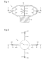
- FIGS. 1 to 3 a first embodiment of an anemometer according to the invention will be explained. It shows FIG. 2 a section through the floor plan plane, which in FIG. 1 is shown as section line AA. FIG. 1 shows accordingly a section through the elevation plane, which in FIG. 2 is marked as section line BB. FIG. 3 shows an axonometric, ie a pseudo-3D representation of the anemometer according to the invention. It should be noted that the mechanical structure of the anemometer according to the FIGS. 1 to 3 is merely illustrative and other embodiments of the invention may have a different appearance.
- the anemometer according to the invention contains an ultrasonic source 2, which is arranged approximately in the center of the anemometer.
- the ultrasonic source 2 contains at least one plasma generating device 20.
- the plasma generating device 20 contains at least two electrodes 21 and 22. Both electrodes are electrically insulated and spaced apart by a discharge gap 25.
- the discharge gap 25 associated ends of the electrodes 21 and 22 may have a relation to the shaft of the electrodes reduced cross-section to facilitate the formation of a plasma discharge in the discharge gap 25 or reduce the breakdown field strength or the spatial extent of the To reduce plasma.
- only one electrode may be present, on which, for example, a corona discharge can be formed or which works against a part of the housing as a counterelectrode.
- the spacing of the electrodes or the discharge gap may in some embodiments of the invention be less than 5 mm, less than 2 mm, less than 1 mm or less than 0.5 mm.
- a smaller discharge gap causes the operation with lower supply voltages.
- the ultrasound source 2 can then ideally be regarded as a point sound source, from which approximately spherical or cylindrical sound waves are emitted almost isotropically in the measuring plane.
- the anemometer has four ultrasonic receivers 31, 32, 33 and 34.
- the ultrasonic receivers are located on two orthogonal axes and are approximately equidistant from the ultrasonic source 2. As a result, in each spatial direction defined by the two axes, a dual measurement of the transit time from the ultrasound source 2 to the ultrasound receivers can be carried out.
- the number of ultrasonic receivers may be larger or smaller.
- At least one ultrasonic receiver is provided to form a measuring path between an ultrasonic source 2 and an ultrasonic receiver 31.
- the number of ultrasound receivers may also be greater, for example, from 5 to 20 or 8 to 16 ultrasound receivers may be present to redundantly measure the transit time and determine the direction and magnitude of the velocity vector of the gas flow with greater accuracy.
- the ultrasonic receivers 31, 32, 33, and 34 each include a planar piezoelectric element which is incident upon impact by the ultrasonic source 2 outgoing sound wave is deformed and converts this deformation into an electrical signal.
- the electrical signal is forwarded via associated connecting cable to an evaluation electronics, which may contain, for example, at least one amplifier and / or filter stages and / or A / D converters and / or time discriminators and / or time-to-digital converter.
- Parts of the evaluation can be implemented in a software that performs the desired function when running this software on a microprocessor or a microcontroller.
- the mechanical construction of the anemometer 1 comprises a foot 45 with which the anemometer can be mounted, for example, on a mast.
- the ultrasonic receivers 31, 32, 33 and 34 are located in mounting pockets 431, 432, 433 and 434, which receive the ultrasonic receiver weather protected.
- the mounting pockets may have an edge formed in the direction of the sound entry surface or an acoustic lens to make it difficult for noise to penetrate and thereby improve the signal-to-noise ratio.
- the ultrasonic receivers can be protected in the mounting pockets by encapsulant from incoming moisture.
- the mounting pockets 431, 432 and 433 are connected to a foot 45 via lower mounting brackets 411, 412, 413 and 414. Furthermore, the mounting pockets 431, 432, 433 and 434 carry upper mounting brackets 421, 422, 423 and 424. At the intersection of the upper mounting bracket a cover plate 46 is attached, which may be circular or polygonal, for example.
- the cover plate 46 carries at its center the upper electrode 21.
- the lower electrode 22 is fixed to the foot 45 so that the discharge gap 25 is formed in the center of the anemometer and in the plane defined by the ultrasonic receivers 31, 32, 33 and 34.
- the upper mounting brackets 421, 422, 423 and 424, the lower mounting brackets 411, 412, 413 and 414, the mounting pockets 431, 432, 433 and 434, the foot 45 and the cover plate 46 may be made of a metal, an alloy or a plastic be, for example by injection molding or die casting.
- the plasma generator 20 and the ultrasonic receiver 31, 32, 33 and 34 are approximately in one plane.
- the operation of the anemometer is again based on the FIG. 4 explained.
- the plasma generating device 20 is powered by a high voltage source 55 with electrical energy.
- the high voltage source 55 may deliver individual electrical pulses to the electrodes 21 and 22 so that a pulsed discharge is formed in the discharge gap 25, each discharge producing a spectrally broadband acoustic wave which propagates concentrically around the discharge gap.
- the means for generating an electrical voltage 55 can generate a plasma discharge in the discharge gap, which burns continuously.
- a modulated ultrasonic wave can be generated by amplitude modulation, which follows the electrical modulation signal with high accuracy and low distortion, since the plasma discharge used for generating sound has a very low mass and no partial oscillations unlike conventional membranes used for sound generation.
- the wavefront 26 concentrically spreads around the center 10 of the anemometer.
- the embodiment in the four ultrasonic receiver 31, 32, 33 and 34 lie on a pitch circle 11 which extends concentrically around the center 10.
- the wavefront 26 reaches all the ultrasonic receivers 31, 32, 33 and 34 at the same time. If the wavefront 26 is distorted by the flow vector 4 of the gas flow, the transit time to the ultrasound receivers located in Stromluv shortens. In FIG. 4 these are the ultrasonic receivers 31 and 32. The propagation time of the acoustic signal 26 to the receivers located in Stromlee extends. In FIG. 4 These are the ultrasound receivers 33 and 34. By evaluating these transit time differences and conversion into polar coordinates of the flow vector 4 can be determined in magnitude and direction.
- an independent temperature sensor 5 can be provided, which determines the temperature of the gas stream, so that the measured transit time differences can be normalized to the temperatures. As a result, temperature changes of the gas stream do not affect the measured flow vector 4.
- the pulse shape of the sound signal 26 can be varied by adjusting the electrical drive signal from the means for generating the high voltage 55, in order to optimize the measurement accuracy, the measurement speed or the energy consumption of the anemometer in this way.
- different pulse shapes of the sound signal 26 may be used for different measurement programs.
Landscapes
- Physics & Mathematics (AREA)
- Engineering & Computer Science (AREA)
- General Physics & Mathematics (AREA)
- Acoustics & Sound (AREA)
- Multimedia (AREA)
- Aviation & Aerospace Engineering (AREA)
- Electromagnetism (AREA)
- Fluid Mechanics (AREA)
- Indicating Or Recording The Presence, Absence, Or Direction Of Movement (AREA)
Abstract
Description
- Die Erfindung betrifft ein Anemometer mit zumindest einer Ultraschallquelle und zumindest einem Ultraschallempfänger. Weiterhin betrifft die Erfindung ein Verfahren zur Bestimmung einer Strömungsgeschwindigkeit oder eines Strömungsvektors eines Gasstroms, bei welchem die Laufzeit von zumindest einem Schallsignal auf einer von einer Ultraschallquelle und einem Ultraschallempfänger begrenzten Messstrecke bestimmt wird. Vorrichtungen und Verfahren der eingangs genannten Art können dazu verwendet werden, die Windrichtung, die Windgeschwindigkeit und die Temperatur zu bestimmen.
- Aus der Praxis sind Ultraschallanemometer bekannt, welche zumindest zwei Piezokeramiken enthalten, welche sowohl als Sender als auch als Empfänger für Ultraschallwellen dienen. Die Piezokristalle sind an zwei gegenüberstehenden Armen montiert und begrenzen eine Messstrecke. Die Laufzeit des Ultraschallsignals über die Messstrecke hängt von der Strömungsgeschwindigkeit und der Temperatur des Gases in der Messstrecke ab. Durch Bestimmen der Laufzeit der Schallsignale in beide Richtungen kann der Einfluss der Temperatur bestimmt werden, sodass die Windgeschwindigkeit und die Temperatur getrennt voneinander bestimmbar sind. Durch mehrere Messstrecken, welche in etwa orthogonal zueinander angeordnet sind, kann ein Strömungsvektor in zwei oder drei Dimensionen bestimmt werden.
- Der Nachteil dieser bekannten Anemometer besteht darin, dass die Laufzeitmessung für jede zu messende Dimension in zwei Richtungen durchgeführt werden muss. Die dreidimensionale Bestimmung eines Strömungsvektors erfordert somit mindestens sechs Messungen. Somit sind der Zeitbedarf und der Energiebedarf für die Bestimmung des Strömungsvektors ebenfalls um einen Faktor 6 vergrößert.
- Ausgehend vom Stand der Technik liegt der Erfindung somit die Aufgabe zugrunde, ein Verfahren und eine Vorrichtung zur Bestimmung einer Strömungsgeschwindigkeit anzugeben, welches eine verbesserte zeitliche Auflösung aufweist und mit geringem Energieeinsatz durchführbar ist.
- Die Aufgabe wird erfindungsgemäß durch ein Anemometer gemäß Anspruch 1 und ein Verfahren gemäß Anspruch 9 gelöst. Vorteilhafte Weiterbildungen der Erfindung finden sich in den Unteransprüchen.
- Erfindungsgemäß wird ein Anemometer vorgeschlagen, welches zumindest eine Ultraschallquelle und zumindest einen Ultraschallempfänger aufweist. Ultraschallquelle und Ultraschallempfänger sind beabstandet zueinander angeordnet. Das von der Ultraschallquelle ausgesandte Schallsignal kann gepulst oder moduliert werden, sodass die Laufzeit des Schallsignales von der Ultraschallquelle zum Ultraschallempfänger bestimmt werden kann. Hierzu wird in an sich bekannter Weise bei Aussendung des Ultraschallsignals von der Ultraschallquelle ein elektrisches Startsignal erzeugt. Der Ultraschallempfänger erzeugt bei Eintreffen des Schallsignales ein elektrisches Stoppsignal, sodass die verstrichene Zeitdauer mit an sich bekannter Elektronik bestimmt werden kann.
- Erfindungsgemäß wird nun vorgeschlagen, dass die Ultraschallquelle zumindest eine Plasmaerzeugungseinrichtung enthält. Für die Zwecke der vorliegenden Erfindung wird unter einem Plasma ein teilweise ionisiertes Gas verstanden. Das Plasma enthält somit Elektronen, Ionen und Neutralteilchen. Deren jeweilige Dichten und Temperaturen können durch die Art der Plasmaerzeugung bzw. durch den Typ der Plasmaerzeugungseinrichtung in weiten Grenzen beeinflusst werden.
- Die erfindungsgemäß eingesetzte Plasmaerzeugungseinrichtung kann die Zusammensetzung des Plasmas zeitlich variieren. Beispielsweise kann das Plasma als kurzer Puls erzeugt werden. Ein kontinuierlich betriebenes Plasma kann moduliert werden, d.h. die Plasmadichte und/oder die Temperatur verändern sich in Abhängigkeit eines elektrischen Eingangssignales mit der Zeit. Da sich das Gasvolumen des Plasmas bei Erwärmung ausdehnt, gibt ein solchermaßen moduliertes Plasma eine ebenso modulierte Schallwelle ab. Gegenüber an sich bekannten Ultraschallquellen weist die erfindungsgemäß vorgeschlagene Plasmaquelle den Vorteil auf, dass das Plasma nahezu masselos ist und daher die Schallwelle dem elektrischen Eingangssignal nahezu verzögerungsfrei folgt. Weiterhin treten im Plasma, anders als bei Festkörpermembranen bekannter Lautsprecher bzw. Ultraschallquellen, keine Partialschwingungen auf, welche zu Verzerrungen des von bekannten Ultraschallquellen abgegebenen Schallsignals führen. Daher wird das zur Modulation verwendete elektrische Signal mit nur geringen Fehlern in ein akustisches Signal gewandelt. Daher ist die Frequenz in weiten Grenzen durchstimmbar, sodass sich nahezu beliebige Kurvenformen erzeugen lassen.
- Die erfindungsgemäß verwendete Ultraschallquelle kann in unterschiedlichen Betriebszuständen eingesetzt werden: In einigen Ausführungsformen der Erfindung können Oberschwingungen des Ultraschallsignals zur Laufzeitmessung verwendet werden. In wiederum anderen Ausführungsformen der Erfindung können die Ultraschallsignale Rechtecksignale sein. In wiederum anderen Ausführungsformen der Erfindung kann die Ultraschallquelle Dämpfungsimpulse erzeugen. Aufgrund der Flexibilität bei der Erzeugung besonderer Pulsformen und/oder Frequenzen des anregenden Ultraschallsignals kann das vorgeschlagene Anemometer mit höherer Genauigkeit messen und/oder einen breiteren Geschwindigkeitsbereich abdecken als bisher bekannte Anemometer mit Piezokristallen oder Piezokeramiken als Ultraschallquelle.
- Da ein in etwa kugelförmiges oder ringförmiges oder zylinderförmiges Plasma Schallwellen in alle Winkelbereiche einer Ebene mit konstanter Intensität aussendet, kann die Messung in einer Mehrzahl von Raumrichtungen gleichzeitig erfolgen, sodass die Messzeit verringert sein kann.
- In einigen Ausführungsformen der Erfindung kann die Plasmaerzeugungseinrichtung zumindest eine Elektrode und zumindest eine Einrichtung zur Erzeugung einer modulierbaren elektrischen Spannung enthalten. In anderen Ausführungsformen der Erfindung kann die Plasmaerzeugungseinrichtung zumindest zwei Elektrode und zumindest eine Einrichtung zur Erzeugung einer modulierbaren elektrischen Spannung enthalten. Zwei Elektroden sind üblicherweise durch einen Spalt beabstandet zueinander angeordnet, sodass sich bei Überschreiten der Durchbruchfeldstärke das Plasma in diesem Spalt ausbildet. Sofern nur eine Elektrode verwendet wird, kann die Gegenelektrode durch das umgebende Luftvolumen und/oder das Gehäuse oder einen Teil des Gehäuses des Anemometers gebildet werden. Sofern die das Plasma anregende Spannung bzw. der das Plasma antreibende Strom amplitudenmoduliert ist, werden auch die Dichte und/oder die Temperatur des Plasmas moduliert, sodass sich durch die sich ausbildende Plasmaflamme ein entsprechend moduliertes Schallsignal erzeugen lässt.
- In einigen Ausführungsformen der Erfindung können die zumindest zwei Elektroden so geformt sein, dass das Plasma eine im Vergleich zur Gesamtlänge der Messstrecke eine geringe Ausdehnung im Raum aufweist und rotationssymmetrisch ist, sodass das Plasma annähernd als Punktschallquelle angesehen werden kann. Eine geringe Ausdehnung kann in einigen Ausführungsformen der Erfindung bedeuten, dass das Verhältnis der Ausdehnung des Plasmas zur Länge der Messstrecke kleiner ist als etwa 0,01 oder kleiner als etwa 0,001 oder kleiner als etwa 0,0001.
- In einigen Ausführungsformen der Erfindung kann das Anemometer zumindest einen Ultraschallempfänger enthalten, welcher ein Piezomikrofon enthält. Die Piezomikrofone enthalten zumindest einen Kristall oder zumindest eine Keramik, dessen elektrische Polarisation sich bei elastischer Verformung verändert. Eine solche Verformung tritt beispielsweise auf, wenn die von der Ultraschallquelle erzeugte Schallwelle auf den piezoelektrischen Festkörper des Piezomikrofons trifft. Somit kann das akustische Signal in ein elektrisches Signal gewandelt werden, welches nachfolgend verstärkt werden kann und einer Auswerteschaltung zugeführt werden kann.
- In einigen Ausführungsformen der Erfindung kann das Piezomikrofon ein planares Piezomikrofon sein. In anderen Ausführungsformen der Erfindung kann das Piezomikrofon ein radiales Piezomikrofon sein. Dabei weist ein planares Piezomikrofon eine größere Empfindlichkeit auf, wohingegen ein radiales Piezomikrofon einen größeren Akzeptanzbereich besitzt. In Abhängigkeit der Größe und der mechanischen Eigenschaften der verwendeten Piezokeramiken kann das Maximum der Empfindlichkeit der Piezomikrofone in einen Frequenzbereich gelegt werden, welcher von der Ultraschallquelle bevorzugt abgestrahlt wird. Hierdurch wird die Empfindlichkeit des Anemometers gesteigert. In einigen Ausführungsformen der Erfindung können die Piezomikrofone so ausgewählt sein, dass die von der Ultraschallquelle ausgesandten Signale besonders verzerrungsarm empfangen werden können, so dass die Genauigkeit der Messung erhöht sein kann.
- In einigen Ausführungsformen der Erfindung enthält das Anemometer zumindest einen Temperatursensor. Der Temperatursensor kann ausgewählt sein aus einem Messwiderstand, beispielsweise einem Platin-Widerstand, einem Silizium-Widerstand, einem Keramik-Kaltleiter oder einem Metalloxid-Widerstand. In anderen Ausführungsformen der Erfindung kann der Temperatursensor einen Schwingquarz als Messelement enthalten, dessen Resonanzfrequenz sich abhängig von der Temperatur verändert. In wiederum anderen Ausführungsformen der Erfindung kann der Temperatursensor ein Thermoelement oder ein Pyrometer oder einen faseroptischen Temperatursensor enthalten oder daraus bestehen. Durch die unabhängige Messung der Temperatur kann der Temperatureinfluss auf die Signallaufzeit kompensiert werden, sodass sich eine höhere Genauigkeit bei der Bestimmung des Geschwindigkeitsvektors ergibt.
- In einigen Ausführungsformen der Erfindung können die Plasmaerzeugungseinrichtung und damit die Ultraschallquelle in etwa im Zentrum des Anemometers angeordnet sein, wobei zumindest drei oder zumindest vier Ultraschallempfänger auf einem Teilkreis um das Zentrum herum angeordnet sind. Eine solche Anordnung erlaubt die Bestimmung von zwei Komponenten des Geschwindigkeitsvektors in der durch die Ultraschallempfänger und die Ultraschallquelle definierten Ebene in nur einer Messung, sodass der Geschwindigkeitsvektor rasch bestimmt werden kann. Hierdurch kann die Messfrequenz erhöht werden kann oder der Energieverbrauch der Messung reduziert sein kann.
- In einigen Ausführungsformen der Erfindung kann sich die Plasmaquelle auf einer gedachten Geraden durch den Mittelpunkt des Teilkreises befinden, welche senkrecht zu der durch den Teilkreis aufgespannten Ebene verläuft. In diesem Fall kann die elektromagnetische Verträglichkeit erhöht sein, da elektromagnetsiche Störungen der Plamaquelle nicht unmittelbar auf die Ultraschallempfänger einwirken können.
- In einigen Ausführungsformen der Erfindung kann die Plasmaerzeugungseinrichtung dazu eingerichtet sein, eine Glimmentladung und/oder eine Funkenentladung und/oder eine Koronaentladung und/oder eine Bogenentladung und/oder eine dielektrisch behinderte Entladung zu erzeugen. Die Art der Entladung kann an die jeweiligen Erfordernisse des Anemometers angepasst werden, um entweder die Messgenauigkeit oder die Messgeschwindigkeit oder den Energieverbrauch des Anemometers zu optimieren. Zur Erzeugung einer dielektrisch behinderte Entladung kann zumindest eine leitfähige Elektrode mit einem Isolator versehen sein und/oder ein Isolator im Entladungsspalt angeordnet sein.
- In einigen Ausführungsformen der Erfindung kann das Schallsignal mit einer Frequenz von etwa 40 kHz bis etwa 200 kHz gepulst werden. Dieser Frequenzbereich zeichnet sich durch ein günstiges Signal-/Rauschverhältnis aus und erlaubt somit eine hohe Messfrequenz und eine hohe Messgenauigkeit.
- In einigen Ausführungsformen der Erfindung kann das Schallsignal gepulst abgegeben werden. Hierzu kann das Plasma ebenfalls gepulst erzeugt werden, sodass der Energieverbrauch des Anemometers verringert ist.
- Nachfolgend soll die Erfindung anhand von Figuren ohne Beschränkung des allgemeinen Erfindungsgedankens näher erläutert werden. Dabei zeigt
- Figur 1
- eine Querschnitt durch ein erfindungsgemäßes Anemometer.
- Figur 2
- zeigt einen Schnitt durch die Grundrissebene des erfindungsgemäßen Anemometers.
- Figur 3
- zeigt eine axonometrische Darstellung des erfindungsgemäßen Anemometers.
- Figur 4
- zeigt die prinzipielle Funktionsweise des erfindungsgemäßen Anemometers.
- Anhand der
Figuren 1 bis 3 wird eine erste Ausführungsform eines erfindungsgemäßen Anemometers erläutert. Dabei zeigtFigur 2 einen Schnitt durch die Grundrissebene, welcher inFigur 1 als Schnittlinie A-A dargestellt ist.Figur 1 zeigt dementsprechend einen Schnitt durch die Aufrissebene, welcher inFigur 2 als Schnittlinie B-B markiert ist.Figur 3 zeigt eine axonometrische, d. h. eine Pseudo-3D-Darstellung des erfindungsgemäßen Anemometers. Es ist darauf hinzuweisen, dass der mechanische Aufbau des Anemometers gemäß derFiguren 1 bis 3 lediglich erläuternd anzusehen ist und andere Ausführungsformen der Erfindung ein anderes Erscheinungsbild aufweisen können. - Das erfindungsgemäße Anemometer enthält eine Ultraschallquelle 2, welche in etwa im Zentrum des Anemometers angeordnet ist. Die Ultraschallquelle 2 enthält zumindest eine Plasmaerzeugungseinrichtung 20. Die Plasmaerzeugungseinrichtung 20 enthält zumindest zwei Elektroden 21 und 22. Beide Elektroden sind elektrisch isoliert und über einen Entladungsspalt 25 voneinander beabstandet. Die dem Entladungsspalt 25 zugeordneten Enden der Elektroden 21 und 22 können einen gegenüber dem Schaft der Elektroden verringerten Querschnitt aufweisen, um durch die an der Spitze auftretende Feldüberhöhung die Ausbildung einer Plasmaentladung im Entladungsspalt 25 zu erleichtern bzw. die Durchbruchfeldstärke zu verringern oder die räumliche Ausdehnung des Plasmas zu verringern. In anderen Ausführungsformen der Erfindung kann nur eine Elektrode vorhanden sein, an welcher beispielsweise eine Koronaentladung ausbildbar ist oder welche gegen einen Teil des Gehäuses als Gegenelektrode arbeitet.
- Der Abstand der Elektroden bzw. der Entladungsspalt kann in einigen Ausführungsformen der Erfindung kleiner als 5 mm, kleiner als 2 mm, kleiner als 1 mm oder kleiner als 0,5 mm sein. Ein kleinerer Entladungsspalt bewirkt dabei den Betrieb mit geringeren Versorgungsspannungen. Weiterhin kann die Ultraschallquelle 2 dann idealisiert als Punktschallquelle betrachtet werden, von welcher in etwa kugelförmige oder zylinderförmige Schallwellen nahezu isotrop in der Messebene ausgesendet werden.
- Im dargestellten Ausführungsbeispiel weist das Anemometer vier Ultraschallempfänger 31, 32, 33 und 34 auf. Die Ultraschallempfänger befinden sich auf zwei orthogonalen Achsen und sind etwa gleich weit von der Ultraschallquelle 2 entfernt. Hierdurch kann in jeder durch die beiden Achsen definierten Raumrichtung eine zweifache Messung der Laufzeit von der Ultraschallquelle 2 zu den Ultraschallempfängern durchgeführt werden. In anderen Ausführungsformen der Erfindung kann die Anzahl der Ultraschallempfänger größer oder geringer sein. Zumindest ist ein Ultraschallempfänger vorhanden, um eine Messstrecke zwischen einer Ultraschallquelle 2 und einem Ultraschallempfänger 31 auszubilden. Zur Bestimmung des Geschwindigkeitsvektors in der durch die Ultraschallempfänger und die Ultraschallquelle aufgespannten Ebene sind zumindest drei Ultraschallempfänger erforderlich, um beide Komponenten des Geschwindigkeitsvektors zu erfassen. In anderen Ausführungsformen der Erfindung kann die Anzahl der Ultraschallempfänger auch größer sein, so können beispielsweise 5 bis 20 oder 8 bis 16 Ultraschallempfänger vorhanden sein, um die Laufzeit redundant zu messen und die Richtung und den Betrag des Geschwindigkeitsvektors der Gasströmung mit größerer Genauigkeit zu bestimmen.
- In einigen Ausführungsformen der Erfindung enthalten die Ultraschallempfänger 31, 32, 33 und 34 jeweils ein planares Piezoelement, welches bei Auftreffen der von der Ultraschallquelle 2 ausgehenden Schallwelle verformt wird und diese Verformung in ein elektrisches Signal wandelt. Das elektrische Signal wird über zugeordnete Anschlusskabel an eine Auswerteelektronik weitergeleitet, welche beispielsweise zumindest einen Verstärker und/oder Filterstufen und/oder A/D-Wandler und/oder Zeitdiskriminatoren und/oder Time-to-Digital-Konverter enthalten kann. Teile der Auswerteelektronik können in einer Software realisiert sein, welche die gewünschte Funktion ausführt, wenn diese Software auf einem Mikroprozessor oder einem Microcontroller läuft.
- Der mechanische Aufbau des Anemometers 1 umfasst einen Fuß 45, mit welchem das Anemometer beispielsweise auf einem Mast montierbar ist. Die Ultraschallempfänger 31, 32, 33 und 34 befinden sich in Montagetaschen 431, 432, 433 und 434, welche die Ultraschallempfänger witterungsgeschützt aufnehmen. Die Montagetaschen können darüber hinaus einen in Richtung der Schalleintrittsfläche ausgebildeten Rand oder eine akustische Linse aufweisen, um das Eindringen von Störgeräuschen zu erschweren und hierdurch das Signal-/Rauschverhältnis zu verbessern. Die Ultraschallempfänger können in den Montagetaschen durch Vergussmasse vor eintretender Feuchtigkeit geschützt sein.
- Die Montagetaschen 431, 432 und 433 sind über untere Montagebügel 411, 412, 413 und 414 mit einem Fuß 45 verbunden. Weiterhin tragen die Montagetaschen 431, 432, 433 und 434 obere Montagebügel 421, 422, 423 und 424. Am Kreuzungspunkt der oberen Montagebügel ist eine Deckelplatte 46 befestigt, welche beispielsweise kreisförmig oder polygonal geformt sein kann.
- Die Deckelplatte 46 trägt in ihrem Mittelpunkt die obere Elektrode 21. Die untere Elektrode 22 ist am Fuß 45 befestigt, sodass sich der Entladungsspalt 25 im Mittelpunkt des Anemometers ausbildet und in der durch die Ultraschallempfänger 31, 32, 33 und 34 definierten Ebene.
- Die oberen Montagebügel 421, 422, 423 und 424, die unteren Montagebügel 411, 412, 413 und 414, die Montagetaschen 431, 432, 433 und 434, der Fuß 45 und die Deckelplatte 46 können aus einem Metall, einer Legierung oder einem Kunststoff gefertigt sein, beispielsweise im Spritzguß- oder Druckgußverfahren.
- Wie
Figur 1 weiter zeigt, befinden sich die Plasmaerzeugungseinrichtung 20 und die Ultraschallempfänger 31, 32, 33 und 34 in etwa in einer Ebene. - Die Funktionsweise des Anemometers wird nochmals anhand der
Figur 4 erläutert. Im Zentrum 10 des Anemometers 1 befindet sich die Plasmaerzeugungseinrichtung 20 der Ultraschallquelle 2. Die Plasmaerzeugungseinrichtung 20 wird von einer Hochspannungsquelle 55 mit elektrischer Energie versorgt. Beispielsweise kann die Hochspannungsquelle 55 einzelne elektrische Pulse an die Elektroden 21 und 22 abgeben, sodass sich eine gepulste Entladung im Entladungsspalt 25 ausbildet, wobei jede Entladung eine spektral breitbandige Schallwelle erzeugt, welche sich konzentrisch um den Entladungsspalt ausbreitet. In anderen Ausführungsformen der Erfindung kann die Einrichtung 55 zur Erzeugung einer elektrischen Spannung eine Plasmaentladung im Entladungsspalt erzeugen, welche kontinuierlich brennt. In diesem Fall kann durch Amplitudenmodulation eine modulierte Ultraschallwelle erzeugt werden, welche dem elektrischen Modulationssignal mit großer Genauigkeit und geringen Verzerrungen folgt, da die zur Schallerzeugung verwendete Plasmaentladung anders als übliche zur Schallerzeugung verwendete Membranen eine sehr geringe Masse aufweist und keine Partialschwingungen besitzt. - Wie
Figur 4 zeigt, breitet sich die Wellenfront 26 konzentrisch um das Zentrum 10 des Anemometers aus. Die im Ausführungsbeispiel vier Ultraschallempfänger 31, 32, 33 und 34 liegen auf einem Teilkreis 11, welcher sich konzentrisch um das Zentrum 10 erstreckt. - Sofern sich das Anemometer 1 in einer ruhenden Gasatmosphäre befindet, erreicht die Wellenfront 26 sämtliche Ultraschallempfänger 31, 32, 33 und 34 zur selben Zeit. Wird die Wellenfront 26 durch den Strömungsvektor 4 des Gasstromes verzerrt, so verkürzt sich die Laufzeit zu den in Stromluv gelegenen Ultraschallempfängern. In
Figur 4 sind dies die Ultraschallempfänger 31 und 32. Die Laufzeit des akustischen Signals 26 zu den in Stromlee gelegenen Empfängern verlängert sich. InFigur 4 sind dies die Ultraschallempfänger 33 und 34. Durch Auswertung dieser Laufzeitdifferenzen und Konvertierung in Polarkoordinaten kann der Strömungsvektor 4 in Betrag und Richtung bestimmt werden. - Da die Schallgeschwindigkeit auch von der Temperatur des Gasstromes abhängt, kann ein unabhängiger Temperatursensor 5 vorgesehen sein, welcher die Temperatur des Gasstromes bestimmt, sodass die gemessenen Laufzeitunterschiede auf die Temperaturen normiert werden können. Hierdurch wirken sich Temperaturänderungen des Gasstromes nicht auf den gemessenen Strömungsvektor 4 aus.
- Die Pulsform des Schallsignals 26 kann durch Anpassen des elektrischen Ansteuersignals aus der Einrichtung 55 zur Erzeugung der Hochspannung variiert werden, um auf diese Weise die Messgenauigkeit, die Messgeschwindigkeit oder den Energieverbrauch des Anemometers zu optimieren. In einigen Ausführungsformen der Erfindung können für unterschiedliche Messprogramme unterschiedliche Pulsformen des Schallsignals 26 verwendet werden.
- Selbstverständlich ist die Erfindung nicht auf die in den Figuren dargestellte Ausführungsform beschränkt. Die vorstehende Beschreibung ist daher nicht als beschränkend, sondern als erläuternd anzusehen. Die nachfolgenden Ansprüche sind so zu verstehen, dass ein genanntes Merkmal in zumindest einer Ausführungsform der Erfindung vorhanden ist. Dies schließt die Anwesenheit weiterer Merkmale nicht aus. Sofern die Ansprüche und die vorstehende Beschreibung "erste" und "zweite" Merkmale definieren, so dient diese Bezeichnung der Unterscheidung zweier gleichartiger Merkmale, ohne eine Rangfolge festzulegen.
Claims (14)
- Anemometer (1) mit zumindest einer Ultraschallquelle (2) und zumindest einem Ultraschallempfänger (31, 32, 33, 34), wobei die Ultraschallquelle (2) zumindest eine Plasmaerzeugungseinrichtung (20) enthält, dadurch gekennzeichnet, dass
die Plasmaerzeugungseinrichtung (20) dazu eingerichtet ist, eine Glimmentladung und/oder eine Koronaentladung und/oder eine Bogenentladung und/oder eine dielektrisch behinderte Entladung zu erzeugen. - Anemometer nach Anspruch 1, dadurch gekennzeichnet, dass die Plasmaerzeugungseinrichtung (20) zumindest eine Elektrode (21, 22) und zumindest eine Einrichtung (55) zur Erzeugung einer modulierbaren elektrischen Spannung enthält.
- Anemometer nach Anspruch 1 oder 2, dadurch gekennzeichnet, dass zumindest ein Ultraschallempfänger (31, 32, 33, 34) ein Piezomikrofon enthält oder
dass zumindest ein Ultraschallempfänger (31, 32, 33, 34) ein planares Piezomikrofon enthält. - Anemometer nach einem der Ansprüche 1 bis 3, weiterhin enthaltend zumindest einen Temperatursensor (5).
- Anemometer nach Anspruch 4, dadurch gekennzeichnet, dass der Temperatursensor (5) ausgewählt ist aus einem Messwiderstand und/oder einem Schwingquarz und/oder einem Thermoelement und/oder faseroptischen Sensor.
- Anemometer nach einem der Ansprüche 1 bis 5, dadurch gekennzeichnet, dass die Plasmaerzeugungseinrichtung (20) etwa im Zentrum (10) des Anemometers (1) angeordnet ist, wobei zumindest drei Ultraschallempfänger (31, 32, 33, 34) auf einem Teilkreis (11) um das Zentrum (10) herum angeordnet sind
- Anemometer nach Anspruch 6, dadurch gekennzeichnet, dass die Plasmaerzeugungseinrichtung und die Ultraschallempfänger (31, 32, 33, 34) in einer Ebene angeordnet sind.
- Anemometer nach einem der Ansprüche 1 bis 7, dadurch gekennzeichnet, dassdie Ultraschallempfänger (31, 32, 33, 34) in zugeordneten Montagetaschen (431, 432, 433, 434) angeordnet sind, welche einen in Richtung der Schalleintrittsfläche ausgebildeten Rand und/oder eine akustische Linse aufweisen.
- Verfahren zur Bestimmung einer Strömungsgeschwindigkeit oder eines Strömungsvektors (4) eines Gasstroms, bei welchem die Laufzeit von zumindest einem Schallsignal (26) auf einer von einem Ultraschallquelle (20) und einem Ultraschallempfänger (31, 32, 33, 34) begrenzten Messstrecke bestimmt wird, wobei das Schallsignal durch zumindest ein moduliertes Plasma (25) erzeugt wird,dadurch gekennzeichnet, dass das Plasma mit einer Glimmentladung und/oder einer Koronaentladung und/oder einer Bogenentladung und/oder einer dielektrisch behinderten Entladung erzeugt wird.
- Verfahren nach Anspruch 9, dadurch gekennzeichnet, dass das Schallsignal (26) gepulst abgegeben wird oder
dass das Schallsignal (26) mit einer Frequenz von etwa 40 kHz bis etwa 200 kHz gepulst wird oder
dass das Schallsignal (26) amplitudenmoduliert wird und/oder
dass das Plasma eine Punktschallquelle bildet. - Verfahren nach einem der Ansprüche 9 bis 10, dadurch gekennzeichnet, dass mit zumindest einem Temperatursensor (5) eine Temperatur des Gasstromes bestimmt wird.
- Verfahren nach einem der Ansprüche 9 bis 11, dadurch gekennzeichnet, dass das Schallsignal (26) durch das zumindest eine modulierte Plasma in mehrere in einer Ebene liegende Richtungen ausgestrahlt wird und in zumindest drei oder zumindest vier Raumrichtungen nachgewiesen wird.
- Verfahren nach einem der Ansprüche 9 bis 12, dadurch gekennzeichnet, dass zumindest drei oder zumindest vier Ultraschallempfänger (31, 32, 33, 34) auf einem Teilkreis (11) mit einem Zentrum angeordnet sind und die Ultraschallquelle (20) etwa im Zentrum (10) des Teilkreis (11) angeordnet ist .
- Verfahren nach einem der Ansprüche 9 bis 13, dadurch gekennzeichnet, dass die Pulsform des durch durch das modulierte Plasma (25) erzeugten Schallsignals durch Anpassen des elektrischen Ansteuersignals einer Einrichtung (55) zur Erzeugung einer Hochspannung variiert wird.
Applications Claiming Priority (1)
| Application Number | Priority Date | Filing Date | Title |
|---|---|---|---|
| DE102014216157.6A DE102014216157A1 (de) | 2014-08-14 | 2014-08-14 | Anemometer und Verfahren zur Bestimmung einer Strömungsgeschwindigkeit |
Publications (2)
| Publication Number | Publication Date |
|---|---|
| EP2985607A1 true EP2985607A1 (de) | 2016-02-17 |
| EP2985607B1 EP2985607B1 (de) | 2017-12-27 |
Family
ID=53800902
Family Applications (1)
| Application Number | Title | Priority Date | Filing Date |
|---|---|---|---|
| EP15180707.0A Not-in-force EP2985607B1 (de) | 2014-08-14 | 2015-08-12 | Anemometer und verfahren zur bestimmung einer strömungsgeschwindigkeit |
Country Status (4)
| Country | Link |
|---|---|
| EP (1) | EP2985607B1 (de) |
| DE (1) | DE102014216157A1 (de) |
| DK (1) | DK2985607T3 (de) |
| ES (1) | ES2661320T3 (de) |
Cited By (4)
| Publication number | Priority date | Publication date | Assignee | Title |
|---|---|---|---|---|
| CN110646636A (zh) * | 2019-10-11 | 2020-01-03 | 电子科技大学 | 一种多功能超声波风速仪 |
| CN111530880A (zh) * | 2020-06-05 | 2020-08-14 | 江苏大橡木集团有限公司 | 一种通风柜面风速报警系统装置 |
| CN114630479A (zh) * | 2017-03-14 | 2022-06-14 | Tdk电子股份有限公司 | 用于产生非热大气压等离子体的设备 |
| CN115575082A (zh) * | 2022-12-09 | 2023-01-06 | 中国空气动力研究与发展中心低速空气动力研究所 | 一种风洞变密度试验风速测量装置、方法及风洞试验方法 |
Families Citing this family (1)
| Publication number | Priority date | Publication date | Assignee | Title |
|---|---|---|---|---|
| DE102022124063A1 (de) * | 2022-09-20 | 2024-03-21 | Bayerische Motoren Werke Aktiengesellschaft | Verfahren zum Betreiben eines Tauchbeckens und Vorrichtung zum Betreiben eines Tauchbeckens |
Citations (8)
| Publication number | Priority date | Publication date | Assignee | Title |
|---|---|---|---|---|
| US2699677A (en) * | 1949-01-18 | 1955-01-18 | Ferranti Ltd | Velocity measuring apparatus |
| US4031756A (en) * | 1976-08-02 | 1977-06-28 | Honeywell Inc. | Ultrasonic air movement and temperature measuring apparatus |
| EP0125061A1 (de) * | 1983-05-04 | 1984-11-14 | Central Electricity Generating Board | Vorrichtung zur Messung der Temperatur und der Strömungsgeschwindigkeit einer Flüssigkeit |
| DE19548882A1 (de) * | 1995-12-29 | 1997-07-03 | Peus Systems Gmbh | Verfahren und Vorrichtung zur Erzeugung und zum Empfang von Schallsignalen, insbesondere von kurzen Schallpulsen |
| DE19617961A1 (de) * | 1996-05-06 | 1997-11-13 | Heuser Ralf | Verfahren zur Messung der Strömungsgeschwindigkeit von gasförmigen oder flüssigen Medien mittels Ultraschall sowie zur Durchführung des Verfahrens geeignetes Meßgerät |
| DE19727960A1 (de) * | 1997-07-01 | 1999-02-04 | Peus Systems Gmbh | Vorrichtung zur zeitlich hochauflösenden Messung eines gasförmigen Volumenstromes, insbesondere eines Abgas-Volumenstromes eines Verbrennungsmotors, in einem von diesem durchströmten Rohr |
| US7628081B1 (en) * | 2007-03-05 | 2009-12-08 | Murray F Feller | Acoustic pulse flow meter |
| DE102013100670A1 (de) * | 2013-01-23 | 2014-07-24 | Endress + Hauser Flowtec Ag | Ultraschall-Durchflußmeßgerät mit Temperaturkompensation |
-
2014
- 2014-08-14 DE DE102014216157.6A patent/DE102014216157A1/de not_active Ceased
-
2015
- 2015-08-12 ES ES15180707.0T patent/ES2661320T3/es active Active
- 2015-08-12 EP EP15180707.0A patent/EP2985607B1/de not_active Not-in-force
- 2015-08-12 DK DK15180707.0T patent/DK2985607T3/en active
Patent Citations (8)
| Publication number | Priority date | Publication date | Assignee | Title |
|---|---|---|---|---|
| US2699677A (en) * | 1949-01-18 | 1955-01-18 | Ferranti Ltd | Velocity measuring apparatus |
| US4031756A (en) * | 1976-08-02 | 1977-06-28 | Honeywell Inc. | Ultrasonic air movement and temperature measuring apparatus |
| EP0125061A1 (de) * | 1983-05-04 | 1984-11-14 | Central Electricity Generating Board | Vorrichtung zur Messung der Temperatur und der Strömungsgeschwindigkeit einer Flüssigkeit |
| DE19548882A1 (de) * | 1995-12-29 | 1997-07-03 | Peus Systems Gmbh | Verfahren und Vorrichtung zur Erzeugung und zum Empfang von Schallsignalen, insbesondere von kurzen Schallpulsen |
| DE19617961A1 (de) * | 1996-05-06 | 1997-11-13 | Heuser Ralf | Verfahren zur Messung der Strömungsgeschwindigkeit von gasförmigen oder flüssigen Medien mittels Ultraschall sowie zur Durchführung des Verfahrens geeignetes Meßgerät |
| DE19727960A1 (de) * | 1997-07-01 | 1999-02-04 | Peus Systems Gmbh | Vorrichtung zur zeitlich hochauflösenden Messung eines gasförmigen Volumenstromes, insbesondere eines Abgas-Volumenstromes eines Verbrennungsmotors, in einem von diesem durchströmten Rohr |
| US7628081B1 (en) * | 2007-03-05 | 2009-12-08 | Murray F Feller | Acoustic pulse flow meter |
| DE102013100670A1 (de) * | 2013-01-23 | 2014-07-24 | Endress + Hauser Flowtec Ag | Ultraschall-Durchflußmeßgerät mit Temperaturkompensation |
Cited By (6)
| Publication number | Priority date | Publication date | Assignee | Title |
|---|---|---|---|---|
| CN114630479A (zh) * | 2017-03-14 | 2022-06-14 | Tdk电子股份有限公司 | 用于产生非热大气压等离子体的设备 |
| CN110646636A (zh) * | 2019-10-11 | 2020-01-03 | 电子科技大学 | 一种多功能超声波风速仪 |
| CN111530880A (zh) * | 2020-06-05 | 2020-08-14 | 江苏大橡木集团有限公司 | 一种通风柜面风速报警系统装置 |
| CN111530880B (zh) * | 2020-06-05 | 2024-09-24 | 江苏大橡木集团有限公司 | 一种通风柜面风速报警系统装置 |
| CN115575082A (zh) * | 2022-12-09 | 2023-01-06 | 中国空气动力研究与发展中心低速空气动力研究所 | 一种风洞变密度试验风速测量装置、方法及风洞试验方法 |
| CN115575082B (zh) * | 2022-12-09 | 2023-03-10 | 中国空气动力研究与发展中心低速空气动力研究所 | 一种风洞变密度试验风速测量装置、方法及风洞试验方法 |
Also Published As
| Publication number | Publication date |
|---|---|
| DK2985607T3 (en) | 2018-03-26 |
| EP2985607B1 (de) | 2017-12-27 |
| DE102014216157A1 (de) | 2016-02-18 |
| ES2661320T3 (es) | 2018-03-28 |
Similar Documents
| Publication | Publication Date | Title |
|---|---|---|
| EP2985607B1 (de) | Anemometer und verfahren zur bestimmung einer strömungsgeschwindigkeit | |
| DE2253833B2 (de) | Piezoelektrisches elektroakustisches wandlerelement | |
| EP3899444A1 (de) | Ultraschall-messgerät | |
| DE102008015916B4 (de) | Verfahren und Vorrichtung zum Testen und Kalibrieren von elektronischen Halbleiterbauelementen, die Schall in elektrische Signale umwandeln | |
| EP3729007B1 (de) | Clamp-on-ultraschall-durchflussmessgerät und verfahren zum justieren des clamp-on-ultraschall-durchflussmessgeräts | |
| DE102015015901B3 (de) | Schwingelement für einen Ultraschall-Transducer mit einer auf einem Translationsgitter basierenden Mehrfachresonanz | |
| WO2001020781A1 (de) | Vorrichtung und verfahren zur ortsaufgelösten detektion | |
| EP2828681A1 (de) | Ultraschallsensor und verfahren zur messung eines objektabstands | |
| DE19727960C2 (de) | Vorrichtung zur zeitlich hochauflösenden Messung eines gasförmigen Volumenstromes, insbesondere eines Abgas-Volumenstromes eines Verbrennungsmotors, in einem von diesem durchströmten Rohr | |
| DE102015015903B3 (de) | Schwingelement für einen Ultraschall-Transducer mit einer auf einer Rotationsperiodizität basierenden Mehrfachresonanz | |
| DE102013110900B4 (de) | Prüfkopf für luftgekoppelten Ultraschall | |
| DE10023306A1 (de) | Verfahren zur Ansteuerung von piezoelektrischen Antrieben in Füllstandmessgeräten | |
| DE102015209234A1 (de) | Vorrichtung zum Aussenden und/oder Empfangen akustischer Signale | |
| DE102011052767A1 (de) | Ultraschalltransducer für einen Näherungssensor | |
| DE102024202876A1 (de) | Ultraschallsensor für ein Fahrzeug | |
| EP2229242B1 (de) | Ultraschallwandler zur erzeugung asymmetrischer schallfelder | |
| DE19548882C2 (de) | Vorrichtung zur zeitlich hochauflösenden Messung des Volumenstromes eines flüssigen oder gasförmigen Mediums in einem von diesem durchströmten Rohr | |
| DE4403646B4 (de) | Drehgeschwindigkeitssensor | |
| DE102007062460A1 (de) | Ultraschallsensor | |
| WO1997042509A1 (de) | Verfahren zur messung der strömungsgeschwindigkeit von gasförmigen oder flüssigen medien mittels ultraschall sowie zur durchführung des verfahrens geeignetes messgerät | |
| DE2831178A1 (de) | Verfahren und einrichtung zur messung des statischen druckes von gasen | |
| DE2845008A1 (de) | Beschleunigungsaufnehmer | |
| DE102020131591B4 (de) | Vibrationssensor mit kapazitiver Schwingungsmessung | |
| DE882317C (de) | Messgeraet zur Sauerstoff-Analyse | |
| DE2443744A1 (de) | Ultraschall-bewegungsdetektor |
Legal Events
| Date | Code | Title | Description |
|---|---|---|---|
| PUAI | Public reference made under article 153(3) epc to a published international application that has entered the european phase |
Free format text: ORIGINAL CODE: 0009012 |
|
| AK | Designated contracting states |
Kind code of ref document: A1 Designated state(s): AL AT BE BG CH CY CZ DE DK EE ES FI FR GB GR HR HU IE IS IT LI LT LU LV MC MK MT NL NO PL PT RO RS SE SI SK SM TR |
|
| AX | Request for extension of the european patent |
Extension state: BA ME |
|
| 17P | Request for examination filed |
Effective date: 20160812 |
|
| RBV | Designated contracting states (corrected) |
Designated state(s): AL AT BE BG CH CY CZ DE DK EE ES FI FR GB GR HR HU IE IS IT LI LT LU LV MC MK MT NL NO PL PT RO RS SE SI SK SM TR |
|
| 17Q | First examination report despatched |
Effective date: 20170201 |
|
| GRAP | Despatch of communication of intention to grant a patent |
Free format text: ORIGINAL CODE: EPIDOSNIGR1 |
|
| INTG | Intention to grant announced |
Effective date: 20170623 |
|
| GRAS | Grant fee paid |
Free format text: ORIGINAL CODE: EPIDOSNIGR3 |
|
| GRAJ | Information related to disapproval of communication of intention to grant by the applicant or resumption of examination proceedings by the epo deleted |
Free format text: ORIGINAL CODE: EPIDOSDIGR1 |
|
| GRAL | Information related to payment of fee for publishing/printing deleted |
Free format text: ORIGINAL CODE: EPIDOSDIGR3 |
|
| GRAP | Despatch of communication of intention to grant a patent |
Free format text: ORIGINAL CODE: EPIDOSNIGR1 |
|
| INTC | Intention to grant announced (deleted) | ||
| GRAA | (expected) grant |
Free format text: ORIGINAL CODE: 0009210 |
|
| INTG | Intention to grant announced |
Effective date: 20171107 |
|
| AK | Designated contracting states |
Kind code of ref document: B1 Designated state(s): AL AT BE BG CH CY CZ DE DK EE ES FI FR GB GR HR HU IE IS IT LI LT LU LV MC MK MT NL NO PL PT RO RS SE SI SK SM TR |
|
| REG | Reference to a national code |
Ref country code: GB Ref legal event code: FG4D Free format text: NOT ENGLISH |
|
| REG | Reference to a national code |
Ref country code: CH Ref legal event code: EP |
|
| REG | Reference to a national code |
Ref country code: AT Ref legal event code: REF Ref document number: 958747 Country of ref document: AT Kind code of ref document: T Effective date: 20180115 |
|
| REG | Reference to a national code |
Ref country code: IE Ref legal event code: FG4D Free format text: LANGUAGE OF EP DOCUMENT: GERMAN |
|
| REG | Reference to a national code |
Ref country code: DE Ref legal event code: R096 Ref document number: 502015002679 Country of ref document: DE |
|
| REG | Reference to a national code |
Ref country code: DK Ref legal event code: T3 Effective date: 20180319 |
|
| REG | Reference to a national code |
Ref country code: ES Ref legal event code: FG2A Ref document number: 2661320 Country of ref document: ES Kind code of ref document: T3 Effective date: 20180328 |
|
| PG25 | Lapsed in a contracting state [announced via postgrant information from national office to epo] |
Ref country code: FI Free format text: LAPSE BECAUSE OF FAILURE TO SUBMIT A TRANSLATION OF THE DESCRIPTION OR TO PAY THE FEE WITHIN THE PRESCRIBED TIME-LIMIT Effective date: 20171227 Ref country code: NO Free format text: LAPSE BECAUSE OF FAILURE TO SUBMIT A TRANSLATION OF THE DESCRIPTION OR TO PAY THE FEE WITHIN THE PRESCRIBED TIME-LIMIT Effective date: 20180327 Ref country code: LT Free format text: LAPSE BECAUSE OF FAILURE TO SUBMIT A TRANSLATION OF THE DESCRIPTION OR TO PAY THE FEE WITHIN THE PRESCRIBED TIME-LIMIT Effective date: 20171227 |
|
| REG | Reference to a national code |
Ref country code: NL Ref legal event code: MP Effective date: 20171227 |
|
| REG | Reference to a national code |
Ref country code: LT Ref legal event code: MG4D |
|
| PG25 | Lapsed in a contracting state [announced via postgrant information from national office to epo] |
Ref country code: HR Free format text: LAPSE BECAUSE OF FAILURE TO SUBMIT A TRANSLATION OF THE DESCRIPTION OR TO PAY THE FEE WITHIN THE PRESCRIBED TIME-LIMIT Effective date: 20171227 Ref country code: GR Free format text: LAPSE BECAUSE OF FAILURE TO SUBMIT A TRANSLATION OF THE DESCRIPTION OR TO PAY THE FEE WITHIN THE PRESCRIBED TIME-LIMIT Effective date: 20180328 Ref country code: RS Free format text: LAPSE BECAUSE OF FAILURE TO SUBMIT A TRANSLATION OF THE DESCRIPTION OR TO PAY THE FEE WITHIN THE PRESCRIBED TIME-LIMIT Effective date: 20171227 Ref country code: LV Free format text: LAPSE BECAUSE OF FAILURE TO SUBMIT A TRANSLATION OF THE DESCRIPTION OR TO PAY THE FEE WITHIN THE PRESCRIBED TIME-LIMIT Effective date: 20171227 Ref country code: BG Free format text: LAPSE BECAUSE OF FAILURE TO SUBMIT A TRANSLATION OF THE DESCRIPTION OR TO PAY THE FEE WITHIN THE PRESCRIBED TIME-LIMIT Effective date: 20180327 |
|
| PG25 | Lapsed in a contracting state [announced via postgrant information from national office to epo] |
Ref country code: NL Free format text: LAPSE BECAUSE OF FAILURE TO SUBMIT A TRANSLATION OF THE DESCRIPTION OR TO PAY THE FEE WITHIN THE PRESCRIBED TIME-LIMIT Effective date: 20171227 |
|
| PG25 | Lapsed in a contracting state [announced via postgrant information from national office to epo] |
Ref country code: SK Free format text: LAPSE BECAUSE OF FAILURE TO SUBMIT A TRANSLATION OF THE DESCRIPTION OR TO PAY THE FEE WITHIN THE PRESCRIBED TIME-LIMIT Effective date: 20171227 Ref country code: CY Free format text: LAPSE BECAUSE OF FAILURE TO SUBMIT A TRANSLATION OF THE DESCRIPTION OR TO PAY THE FEE WITHIN THE PRESCRIBED TIME-LIMIT Effective date: 20171227 Ref country code: EE Free format text: LAPSE BECAUSE OF FAILURE TO SUBMIT A TRANSLATION OF THE DESCRIPTION OR TO PAY THE FEE WITHIN THE PRESCRIBED TIME-LIMIT Effective date: 20171227 Ref country code: CZ Free format text: LAPSE BECAUSE OF FAILURE TO SUBMIT A TRANSLATION OF THE DESCRIPTION OR TO PAY THE FEE WITHIN THE PRESCRIBED TIME-LIMIT Effective date: 20171227 |
|
| REG | Reference to a national code |
Ref country code: FR Ref legal event code: PLFP Year of fee payment: 4 |
|
| PG25 | Lapsed in a contracting state [announced via postgrant information from national office to epo] |
Ref country code: SM Free format text: LAPSE BECAUSE OF FAILURE TO SUBMIT A TRANSLATION OF THE DESCRIPTION OR TO PAY THE FEE WITHIN THE PRESCRIBED TIME-LIMIT Effective date: 20171227 Ref country code: PL Free format text: LAPSE BECAUSE OF FAILURE TO SUBMIT A TRANSLATION OF THE DESCRIPTION OR TO PAY THE FEE WITHIN THE PRESCRIBED TIME-LIMIT Effective date: 20171227 Ref country code: RO Free format text: LAPSE BECAUSE OF FAILURE TO SUBMIT A TRANSLATION OF THE DESCRIPTION OR TO PAY THE FEE WITHIN THE PRESCRIBED TIME-LIMIT Effective date: 20171227 Ref country code: IS Free format text: LAPSE BECAUSE OF FAILURE TO SUBMIT A TRANSLATION OF THE DESCRIPTION OR TO PAY THE FEE WITHIN THE PRESCRIBED TIME-LIMIT Effective date: 20180427 |
|
| PG25 | Lapsed in a contracting state [announced via postgrant information from national office to epo] |
Ref country code: MT Free format text: LAPSE BECAUSE OF FAILURE TO SUBMIT A TRANSLATION OF THE DESCRIPTION OR TO PAY THE FEE WITHIN THE PRESCRIBED TIME-LIMIT Effective date: 20171227 |
|
| REG | Reference to a national code |
Ref country code: DE Ref legal event code: R097 Ref document number: 502015002679 Country of ref document: DE |
|
| PGFP | Annual fee paid to national office [announced via postgrant information from national office to epo] |
Ref country code: FR Payment date: 20180824 Year of fee payment: 9 Ref country code: ES Payment date: 20180921 Year of fee payment: 4 |
|
| PLBE | No opposition filed within time limit |
Free format text: ORIGINAL CODE: 0009261 |
|
| STAA | Information on the status of an ep patent application or granted ep patent |
Free format text: STATUS: NO OPPOSITION FILED WITHIN TIME LIMIT |
|
| PGFP | Annual fee paid to national office [announced via postgrant information from national office to epo] |
Ref country code: DK Payment date: 20180827 Year of fee payment: 4 |
|
| 26N | No opposition filed |
Effective date: 20180928 |
|
| PG25 | Lapsed in a contracting state [announced via postgrant information from national office to epo] |
Ref country code: SI Free format text: LAPSE BECAUSE OF FAILURE TO SUBMIT A TRANSLATION OF THE DESCRIPTION OR TO PAY THE FEE WITHIN THE PRESCRIBED TIME-LIMIT Effective date: 20171227 |
|
| PG25 | Lapsed in a contracting state [announced via postgrant information from national office to epo] |
Ref country code: MC Free format text: LAPSE BECAUSE OF FAILURE TO SUBMIT A TRANSLATION OF THE DESCRIPTION OR TO PAY THE FEE WITHIN THE PRESCRIBED TIME-LIMIT Effective date: 20171227 |
|
| REG | Reference to a national code |
Ref country code: CH Ref legal event code: PL |
|
| PG25 | Lapsed in a contracting state [announced via postgrant information from national office to epo] |
Ref country code: CH Free format text: LAPSE BECAUSE OF NON-PAYMENT OF DUE FEES Effective date: 20180831 Ref country code: LU Free format text: LAPSE BECAUSE OF NON-PAYMENT OF DUE FEES Effective date: 20180812 Ref country code: LI Free format text: LAPSE BECAUSE OF NON-PAYMENT OF DUE FEES Effective date: 20180831 |
|
| REG | Reference to a national code |
Ref country code: BE Ref legal event code: MM Effective date: 20180831 |
|
| REG | Reference to a national code |
Ref country code: IE Ref legal event code: MM4A |
|
| PG25 | Lapsed in a contracting state [announced via postgrant information from national office to epo] |
Ref country code: IE Free format text: LAPSE BECAUSE OF NON-PAYMENT OF DUE FEES Effective date: 20180812 |
|
| PG25 | Lapsed in a contracting state [announced via postgrant information from national office to epo] |
Ref country code: BE Free format text: LAPSE BECAUSE OF NON-PAYMENT OF DUE FEES Effective date: 20180831 |
|
| PG25 | Lapsed in a contracting state [announced via postgrant information from national office to epo] |
Ref country code: TR Free format text: LAPSE BECAUSE OF FAILURE TO SUBMIT A TRANSLATION OF THE DESCRIPTION OR TO PAY THE FEE WITHIN THE PRESCRIBED TIME-LIMIT Effective date: 20171227 |
|
| REG | Reference to a national code |
Ref country code: DK Ref legal event code: EBP Effective date: 20190831 |
|
| GBPC | Gb: european patent ceased through non-payment of renewal fee |
Effective date: 20190812 |
|
| PG25 | Lapsed in a contracting state [announced via postgrant information from national office to epo] |
Ref country code: PT Free format text: LAPSE BECAUSE OF FAILURE TO SUBMIT A TRANSLATION OF THE DESCRIPTION OR TO PAY THE FEE WITHIN THE PRESCRIBED TIME-LIMIT Effective date: 20171227 |
|
| PG25 | Lapsed in a contracting state [announced via postgrant information from national office to epo] |
Ref country code: SE Free format text: LAPSE BECAUSE OF FAILURE TO SUBMIT A TRANSLATION OF THE DESCRIPTION OR TO PAY THE FEE WITHIN THE PRESCRIBED TIME-LIMIT Effective date: 20171227 Ref country code: MK Free format text: LAPSE BECAUSE OF NON-PAYMENT OF DUE FEES Effective date: 20171227 Ref country code: HU Free format text: LAPSE BECAUSE OF FAILURE TO SUBMIT A TRANSLATION OF THE DESCRIPTION OR TO PAY THE FEE WITHIN THE PRESCRIBED TIME-LIMIT; INVALID AB INITIO Effective date: 20150812 |
|
| PG25 | Lapsed in a contracting state [announced via postgrant information from national office to epo] |
Ref country code: FR Free format text: LAPSE BECAUSE OF NON-PAYMENT OF DUE FEES Effective date: 20190831 Ref country code: AL Free format text: LAPSE BECAUSE OF FAILURE TO SUBMIT A TRANSLATION OF THE DESCRIPTION OR TO PAY THE FEE WITHIN THE PRESCRIBED TIME-LIMIT Effective date: 20171227 Ref country code: DK Free format text: LAPSE BECAUSE OF NON-PAYMENT OF DUE FEES Effective date: 20190831 |
|
| PG25 | Lapsed in a contracting state [announced via postgrant information from national office to epo] |
Ref country code: IT Free format text: LAPSE BECAUSE OF NON-PAYMENT OF DUE FEES Effective date: 20190812 Ref country code: GB Free format text: LAPSE BECAUSE OF NON-PAYMENT OF DUE FEES Effective date: 20190812 |
|
| REG | Reference to a national code |
Ref country code: ES Ref legal event code: FD2A Effective date: 20210105 |
|
| PG25 | Lapsed in a contracting state [announced via postgrant information from national office to epo] |
Ref country code: ES Free format text: LAPSE BECAUSE OF NON-PAYMENT OF DUE FEES Effective date: 20190813 |
|
| REG | Reference to a national code |
Ref country code: AT Ref legal event code: MM01 Ref document number: 958747 Country of ref document: AT Kind code of ref document: T Effective date: 20200812 |
|
| PG25 | Lapsed in a contracting state [announced via postgrant information from national office to epo] |
Ref country code: AT Free format text: LAPSE BECAUSE OF NON-PAYMENT OF DUE FEES Effective date: 20200812 |
|
| PGFP | Annual fee paid to national office [announced via postgrant information from national office to epo] |
Ref country code: DE Payment date: 20220822 Year of fee payment: 8 |
|
| P01 | Opt-out of the competence of the unified patent court (upc) registered |
Effective date: 20230524 |
|
| REG | Reference to a national code |
Ref country code: DE Ref legal event code: R119 Ref document number: 502015002679 Country of ref document: DE |
|
| PG25 | Lapsed in a contracting state [announced via postgrant information from national office to epo] |
Ref country code: DE Free format text: LAPSE BECAUSE OF NON-PAYMENT OF DUE FEES Effective date: 20240301 |