EP2985482A2 - Butée de débrayage auto-réglable - Google Patents
Butée de débrayage auto-réglable Download PDFInfo
- Publication number
- EP2985482A2 EP2985482A2 EP15160118.4A EP15160118A EP2985482A2 EP 2985482 A2 EP2985482 A2 EP 2985482A2 EP 15160118 A EP15160118 A EP 15160118A EP 2985482 A2 EP2985482 A2 EP 2985482A2
- Authority
- EP
- European Patent Office
- Prior art keywords
- sealing
- bearing ring
- sliding sleeve
- radial
- release
- Prior art date
- Legal status (The legal status is an assumption and is not a legal conclusion. Google has not performed a legal analysis and makes no representation as to the accuracy of the status listed.)
- Granted
Links
- 238000007789 sealing Methods 0.000 claims abstract description 257
- 238000005096 rolling process Methods 0.000 claims abstract description 20
- 230000000903 blocking effect Effects 0.000 claims description 24
- 239000000314 lubricant Substances 0.000 claims description 13
- 239000004519 grease Substances 0.000 claims description 6
- 239000000356 contaminant Substances 0.000 claims description 5
- 239000002245 particle Substances 0.000 description 18
- 238000005299 abrasion Methods 0.000 description 10
- 239000002981 blocking agent Substances 0.000 description 10
- 239000000428 dust Substances 0.000 description 9
- 238000013461 design Methods 0.000 description 8
- 238000012423 maintenance Methods 0.000 description 7
- 230000008439 repair process Effects 0.000 description 6
- 230000002093 peripheral effect Effects 0.000 description 5
- 230000008901 benefit Effects 0.000 description 4
- 230000000994 depressogenic effect Effects 0.000 description 4
- 230000000694 effects Effects 0.000 description 4
- 230000000149 penetrating effect Effects 0.000 description 4
- 230000035515 penetration Effects 0.000 description 4
- 239000000126 substance Substances 0.000 description 4
- 238000011109 contamination Methods 0.000 description 3
- 230000008878 coupling Effects 0.000 description 3
- 238000010168 coupling process Methods 0.000 description 3
- 238000005859 coupling reaction Methods 0.000 description 3
- 229920001971 elastomer Polymers 0.000 description 3
- 239000000806 elastomer Substances 0.000 description 3
- 230000017525 heat dissipation Effects 0.000 description 3
- 238000000034 method Methods 0.000 description 3
- 230000008569 process Effects 0.000 description 3
- 230000009467 reduction Effects 0.000 description 3
- 239000007787 solid Substances 0.000 description 3
- 239000003351 stiffener Substances 0.000 description 3
- 229910000831 Steel Inorganic materials 0.000 description 2
- 239000000853 adhesive Substances 0.000 description 2
- 230000001070 adhesive effect Effects 0.000 description 2
- 239000003570 air Substances 0.000 description 2
- 239000012080 ambient air Substances 0.000 description 2
- 230000004888 barrier function Effects 0.000 description 2
- 230000005540 biological transmission Effects 0.000 description 2
- 238000010276 construction Methods 0.000 description 2
- 230000008021 deposition Effects 0.000 description 2
- 239000000463 material Substances 0.000 description 2
- 229910001220 stainless steel Inorganic materials 0.000 description 2
- 239000010935 stainless steel Substances 0.000 description 2
- 239000010959 steel Substances 0.000 description 2
- 230000002411 adverse Effects 0.000 description 1
- 239000012754 barrier agent Substances 0.000 description 1
- 238000011161 development Methods 0.000 description 1
- 230000018109 developmental process Effects 0.000 description 1
- 238000007599 discharging Methods 0.000 description 1
- 230000007613 environmental effect Effects 0.000 description 1
- 239000007788 liquid Substances 0.000 description 1
- 230000005923 long-lasting effect Effects 0.000 description 1
- 238000004519 manufacturing process Methods 0.000 description 1
- 238000005065 mining Methods 0.000 description 1
- 239000000203 mixture Substances 0.000 description 1
- 238000003860 storage Methods 0.000 description 1
- 230000008961 swelling Effects 0.000 description 1
- 238000012546 transfer Methods 0.000 description 1
- 238000011144 upstream manufacturing Methods 0.000 description 1
- XLYOFNOQVPJJNP-UHFFFAOYSA-N water Substances O XLYOFNOQVPJJNP-UHFFFAOYSA-N 0.000 description 1
Images


Classifications
-
- F—MECHANICAL ENGINEERING; LIGHTING; HEATING; WEAPONS; BLASTING
- F16—ENGINEERING ELEMENTS AND UNITS; GENERAL MEASURES FOR PRODUCING AND MAINTAINING EFFECTIVE FUNCTIONING OF MACHINES OR INSTALLATIONS; THERMAL INSULATION IN GENERAL
- F16D—COUPLINGS FOR TRANSMITTING ROTATION; CLUTCHES; BRAKES
- F16D23/00—Details of mechanically-actuated clutches not specific for one distinct type
- F16D23/12—Mechanical clutch-actuating mechanisms arranged outside the clutch as such
- F16D23/14—Clutch-actuating sleeves or bearings; Actuating members directly connected to clutch-actuating sleeves or bearings
- F16D23/148—Guide-sleeve receiving the clutch release bearing
-
- F—MECHANICAL ENGINEERING; LIGHTING; HEATING; WEAPONS; BLASTING
- F16—ENGINEERING ELEMENTS AND UNITS; GENERAL MEASURES FOR PRODUCING AND MAINTAINING EFFECTIVE FUNCTIONING OF MACHINES OR INSTALLATIONS; THERMAL INSULATION IN GENERAL
- F16C—SHAFTS; FLEXIBLE SHAFTS; ELEMENTS OR CRANKSHAFT MECHANISMS; ROTARY BODIES OTHER THAN GEARING ELEMENTS; BEARINGS
- F16C33/00—Parts of bearings; Special methods for making bearings or parts thereof
- F16C33/72—Sealings
- F16C33/76—Sealings of ball or roller bearings
- F16C33/78—Sealings of ball or roller bearings with a diaphragm, disc, or ring, with or without resilient members
- F16C33/7816—Details of the sealing or parts thereof, e.g. geometry, material
- F16C33/782—Details of the sealing or parts thereof, e.g. geometry, material of the sealing region
-
- F—MECHANICAL ENGINEERING; LIGHTING; HEATING; WEAPONS; BLASTING
- F16—ENGINEERING ELEMENTS AND UNITS; GENERAL MEASURES FOR PRODUCING AND MAINTAINING EFFECTIVE FUNCTIONING OF MACHINES OR INSTALLATIONS; THERMAL INSULATION IN GENERAL
- F16C—SHAFTS; FLEXIBLE SHAFTS; ELEMENTS OR CRANKSHAFT MECHANISMS; ROTARY BODIES OTHER THAN GEARING ELEMENTS; BEARINGS
- F16C33/00—Parts of bearings; Special methods for making bearings or parts thereof
- F16C33/72—Sealings
- F16C33/76—Sealings of ball or roller bearings
- F16C33/78—Sealings of ball or roller bearings with a diaphragm, disc, or ring, with or without resilient members
- F16C33/784—Sealings of ball or roller bearings with a diaphragm, disc, or ring, with or without resilient members mounted to a groove in the inner surface of the outer race and extending toward the inner race
- F16C33/7843—Sealings of ball or roller bearings with a diaphragm, disc, or ring, with or without resilient members mounted to a groove in the inner surface of the outer race and extending toward the inner race with a single annular sealing disc
- F16C33/7853—Sealings of ball or roller bearings with a diaphragm, disc, or ring, with or without resilient members mounted to a groove in the inner surface of the outer race and extending toward the inner race with a single annular sealing disc with one or more sealing lips to contact the inner race
-
- F—MECHANICAL ENGINEERING; LIGHTING; HEATING; WEAPONS; BLASTING
- F16—ENGINEERING ELEMENTS AND UNITS; GENERAL MEASURES FOR PRODUCING AND MAINTAINING EFFECTIVE FUNCTIONING OF MACHINES OR INSTALLATIONS; THERMAL INSULATION IN GENERAL
- F16C—SHAFTS; FLEXIBLE SHAFTS; ELEMENTS OR CRANKSHAFT MECHANISMS; ROTARY BODIES OTHER THAN GEARING ELEMENTS; BEARINGS
- F16C33/00—Parts of bearings; Special methods for making bearings or parts thereof
- F16C33/72—Sealings
- F16C33/76—Sealings of ball or roller bearings
- F16C33/78—Sealings of ball or roller bearings with a diaphragm, disc, or ring, with or without resilient members
- F16C33/784—Sealings of ball or roller bearings with a diaphragm, disc, or ring, with or without resilient members mounted to a groove in the inner surface of the outer race and extending toward the inner race
- F16C33/7859—Sealings of ball or roller bearings with a diaphragm, disc, or ring, with or without resilient members mounted to a groove in the inner surface of the outer race and extending toward the inner race with a further sealing element
- F16C33/7863—Sealings of ball or roller bearings with a diaphragm, disc, or ring, with or without resilient members mounted to a groove in the inner surface of the outer race and extending toward the inner race with a further sealing element mounted to the inner race, e.g. a flinger to use centrifugal effect
-
- F—MECHANICAL ENGINEERING; LIGHTING; HEATING; WEAPONS; BLASTING
- F16—ENGINEERING ELEMENTS AND UNITS; GENERAL MEASURES FOR PRODUCING AND MAINTAINING EFFECTIVE FUNCTIONING OF MACHINES OR INSTALLATIONS; THERMAL INSULATION IN GENERAL
- F16C—SHAFTS; FLEXIBLE SHAFTS; ELEMENTS OR CRANKSHAFT MECHANISMS; ROTARY BODIES OTHER THAN GEARING ELEMENTS; BEARINGS
- F16C33/00—Parts of bearings; Special methods for making bearings or parts thereof
- F16C33/72—Sealings
- F16C33/76—Sealings of ball or roller bearings
- F16C33/78—Sealings of ball or roller bearings with a diaphragm, disc, or ring, with or without resilient members
- F16C33/784—Sealings of ball or roller bearings with a diaphragm, disc, or ring, with or without resilient members mounted to a groove in the inner surface of the outer race and extending toward the inner race
- F16C33/7859—Sealings of ball or roller bearings with a diaphragm, disc, or ring, with or without resilient members mounted to a groove in the inner surface of the outer race and extending toward the inner race with a further sealing element
- F16C33/7866—Sealings of ball or roller bearings with a diaphragm, disc, or ring, with or without resilient members mounted to a groove in the inner surface of the outer race and extending toward the inner race with a further sealing element with sealing lips
-
- F—MECHANICAL ENGINEERING; LIGHTING; HEATING; WEAPONS; BLASTING
- F16—ENGINEERING ELEMENTS AND UNITS; GENERAL MEASURES FOR PRODUCING AND MAINTAINING EFFECTIVE FUNCTIONING OF MACHINES OR INSTALLATIONS; THERMAL INSULATION IN GENERAL
- F16C—SHAFTS; FLEXIBLE SHAFTS; ELEMENTS OR CRANKSHAFT MECHANISMS; ROTARY BODIES OTHER THAN GEARING ELEMENTS; BEARINGS
- F16C33/00—Parts of bearings; Special methods for making bearings or parts thereof
- F16C33/72—Sealings
- F16C33/76—Sealings of ball or roller bearings
- F16C33/78—Sealings of ball or roller bearings with a diaphragm, disc, or ring, with or without resilient members
- F16C33/7886—Sealings of ball or roller bearings with a diaphragm, disc, or ring, with or without resilient members mounted outside the gap between the inner and outer races, e.g. sealing rings mounted to an end face or outer surface of a race
-
- F—MECHANICAL ENGINEERING; LIGHTING; HEATING; WEAPONS; BLASTING
- F16—ENGINEERING ELEMENTS AND UNITS; GENERAL MEASURES FOR PRODUCING AND MAINTAINING EFFECTIVE FUNCTIONING OF MACHINES OR INSTALLATIONS; THERMAL INSULATION IN GENERAL
- F16D—COUPLINGS FOR TRANSMITTING ROTATION; CLUTCHES; BRAKES
- F16D23/00—Details of mechanically-actuated clutches not specific for one distinct type
- F16D23/12—Mechanical clutch-actuating mechanisms arranged outside the clutch as such
- F16D23/14—Clutch-actuating sleeves or bearings; Actuating members directly connected to clutch-actuating sleeves or bearings
-
- F—MECHANICAL ENGINEERING; LIGHTING; HEATING; WEAPONS; BLASTING
- F16—ENGINEERING ELEMENTS AND UNITS; GENERAL MEASURES FOR PRODUCING AND MAINTAINING EFFECTIVE FUNCTIONING OF MACHINES OR INSTALLATIONS; THERMAL INSULATION IN GENERAL
- F16C—SHAFTS; FLEXIBLE SHAFTS; ELEMENTS OR CRANKSHAFT MECHANISMS; ROTARY BODIES OTHER THAN GEARING ELEMENTS; BEARINGS
- F16C19/00—Bearings with rolling contact, for exclusively rotary movement
- F16C19/02—Bearings with rolling contact, for exclusively rotary movement with bearing balls essentially of the same size in one or more circular rows
- F16C19/04—Bearings with rolling contact, for exclusively rotary movement with bearing balls essentially of the same size in one or more circular rows for radial load mainly
- F16C19/06—Bearings with rolling contact, for exclusively rotary movement with bearing balls essentially of the same size in one or more circular rows for radial load mainly with a single row or balls
-
- F—MECHANICAL ENGINEERING; LIGHTING; HEATING; WEAPONS; BLASTING
- F16—ENGINEERING ELEMENTS AND UNITS; GENERAL MEASURES FOR PRODUCING AND MAINTAINING EFFECTIVE FUNCTIONING OF MACHINES OR INSTALLATIONS; THERMAL INSULATION IN GENERAL
- F16C—SHAFTS; FLEXIBLE SHAFTS; ELEMENTS OR CRANKSHAFT MECHANISMS; ROTARY BODIES OTHER THAN GEARING ELEMENTS; BEARINGS
- F16C2361/00—Apparatus or articles in engineering in general
- F16C2361/43—Clutches, e.g. disengaging bearing
-
- F—MECHANICAL ENGINEERING; LIGHTING; HEATING; WEAPONS; BLASTING
- F16—ENGINEERING ELEMENTS AND UNITS; GENERAL MEASURES FOR PRODUCING AND MAINTAINING EFFECTIVE FUNCTIONING OF MACHINES OR INSTALLATIONS; THERMAL INSULATION IN GENERAL
- F16D—COUPLINGS FOR TRANSMITTING ROTATION; CLUTCHES; BRAKES
- F16D2300/00—Special features for couplings or clutches
- F16D2300/08—Details or arrangements of sealings not provided for in group F16D3/84
Definitions
- the invention relates to a release device for a friction clutch of a motor vehicle, comprising a guide tube, a sliding sleeve, which is axially displaceable on the guide tube and at least one radial and axial opening comprises a holding portion to which a retaining plate is attached, which a self-aligning release bearing to a Presses the flange of the sliding sleeve and at least one radial opening, the release bearing, which rotatably to the sliding sleeve arranged outer bearing ring, between the outer and an inner bearing ring arranged rolling elements and a circumferential inner bearing ring, wherein the inner bearing ring with an actuating element of the friction clutch in An operative connection is, a slinger, which is connected to the inner bearing ring and a first and second sealing element, which are connected to the outer bearing ring.
- a friction clutch is mainly installed in motor vehicles to separate and close the power flow between an engine and a transmission when starting or changing gears. It can be operated mechanically, hydraulically or electrically and consists of a clutch disc, which is pressed by one or more springs with a pressure plate to the flywheel of the engine. Upon actuation of the clutch, the spring pressure is overcome by the release lever, so that the disc can rotate freely and the clutch is disconnected.
- the friction clutch is switchable during operation and uses the frictional resistance between two plates to transfer forces from one plate to another. Therefore, the clutch performs a large friction work, resulting in a strong mechanical abrasion of the clutch, which is determined by the operating conditions and therefore can be influenced only insignificantly. Added to this is the thermal load on the coupling.
- Release devices for actuating a friction clutch of a motor vehicle comprise as a main component a release bearing designed as a roller bearing.
- the release bearing is used in the drive train of motor vehicles.
- a careful sealing of the bearing interior is required.
- the rolling elements are in contact with the raceways of the bearing in force-transmitting rolling contact.
- contacting and / or contact-free sealing arrangements are provided directly on the roller bearing or on components adjacent to the bearing.
- Such sealing arrangements are usually elastomer and / or labyrinth seals, which may additionally comprise receiving areas filled with a blocking agent.
- the main function of the seal assembly is on the one hand the avoidance of lubricant leakage and on the other hand the reduction of dirt or moisture ingress into the bearing interior. In contact seals, however, wear is inevitable.
- the bearings of the coupling are contaminated by moisture, suspended solids and other dirt particles from the ambient air. This is especially true for rolling bearing seals in motor vehicles, which are exposed to extremely large amounts of dust and dirt, such as This is the case in road and mining, as well as in agriculture and forestry.
- the dusts and suspended matter contained in the ambient air easily enter the bell housing and are transported there with the circulating air directly to the coupling release device. There they are stored together with the already present clutch wear, preferably on the sealing elements of the release bearing. Due to the swelling axial load of a release bearing and the wear-promoting aggressiveness of the dusts and suspended matter, there is a continuous reduction in the effectiveness of the sealing systems of the camp. This means that they soon no longer work, which can ultimately lead to failure of the release bearing and thus the entire friction clutch.
- the blocking means can be pushed out step by step in a radial self-adjustment of the release bearing from the receiving area.
- the barrier layer can also dissolve from one of the components, which allows the entry of dusts and suspended matter.
- the blocking agent can be attacked directly by the dusts and suspended particles that collect in and on the release bearing become. This negatively affects the blocking agent property, so that the blocking agent gradually becomes the main disturbance factor for the main seal.
- the release bearing has a cover element.
- the cover element is fixed to the outer, rotationally fixed bearing ring and covers a located between the bearing rings access area of the bearing interior.
- a receiving area filled with a blocking means is formed between the cover element and the circumferential bearing ring.
- the locking means acts as an upstream seal and blocks the entry of dirt into the release bearing. Due to the arrangement of the cover element, the shape of the receiving area filled with blocking means is not influenced during the self-adjustment of the release bearing. In this way, the dust and suspended load of the sealing system is greatly reduced.
- the blocking agent is attacked directly by the coarse dusts and suspended matter, so that the blocking agent property is adversely affected. Furthermore, due to the undefined shape of the receiving area and the centrifugal force effect, the blocking means will move radially outwards along the inner side of the cover element, so that the amount of blocking means is reduced continuously. This gradually allows the entry of foreign particles into the release bearing. In this way, therefore, only time is gained until the wear-related failure of the release bearing.
- a release device for a friction clutch of a motor vehicle with a self-aligning release bearing which is reliable and long-lasting protection against contamination, such as suspended matter, dusts and moisture ingress. It is therefore of great importance to seal a release bearing so well that the amount of contaminant is local, i. in the area of the bearing interior, maximum is reduced and that the seal is subject to the lowest possible own wear. Based on this point, the invention therefore has the task of providing bearings whose sealing elements ensure longer life of the release bearing and thus lower downtime and repair or maintenance costs even under extreme external and wear-promoting conditions.
- Another aspect of extending the life of the release bearing is to remove the heat generated in the bearing to the outside, since the heat dissipated negatively affects the life of the bearing.
- this problem is not addressed.
- These are, however, strongly encapsulated, for example by a sliding sleeve, which leads to a reduction of heat dissipation. Therefore, it has become the invention further set the task to cool the rolling bearing targeted and dissipate the excess heat in the environment.
- the object of the invention is therefore to provide a release device for a friction clutch of a motor vehicle whose failure-related repair and maintenance times are reduced to a minimum by the release bearing is reliably and durable protected against penetrating into the bearing interior contaminants and leaking lubricants.
- the heat generated at the release bearing is reliably dissipated, which additionally increases the lifetime of the bearing.
- a disengaging device for a friction clutch of a motor vehicle which is a guide tube, an axially displaceable on the guide tube sliding sleeve, a holding portion to which a retaining plate is attached, a self-aligning release bearing, a centrifugal disc and a first and second sealing element comprises.
- the release device can be built in pulled or pressed construction.
- sliding sleeve is understood to be an axially displaceable sleeve on the guide tube.
- the sliding sleeve is made of any material, but this is not essential in the invention. This is in addition to its central opening provided with further openings, which openings are functional openings for increasing the air circulation and / or the removal of dirt or heat. These are arranged on the outer edge of the sliding sleeve.
- the openings are radially and axially aligned.
- the sliding sleeve comprises at least one radial and axial opening.
- the radial and axial openings are arranged at the level of the release bearing.
- the sliding sleeve for a pulled release bearing comprises at least two radial openings and an axial opening.
- the sliding sleeve preferably comprises a radial opening and at least two axial openings.
- the radial openings are preferably configured to taper outwardly so as to ensure that debris is conducted outwardly of the release bearing due to its own weight and / or heat. At the same time due to the special design of the openings and the centrifugal force flow of the centrifugal disc thus the dirt entry is reduced in the release bearing.
- the axial opening is designed so that it tapers to the outside.
- heat is mainly discharged through an outwardly narrowing, funnel-shaped opening from the release bearing.
- it can not be prevented that dirt is transported away via the axial opening from the release bearing to the outside.
- the deduced amount of dirt is negligible, as this is preferably discharged through the radial openings due to its own weight and the centrifugal force.
- the sliding sleeve can also have an introduced groove, which facilitates the mounting of the retaining plate and ensures that any dirt entering the bearing is immediately removed from the bearing.
- holding portion refers to a portion to which a retaining plate is attached, which presses a self-aligning release bearing on a flange of the sliding sleeve. Between this flange and the outer bearing ring of the release bearing is a spring element.
- the flange is a radial flange.
- the holding plate is rolled on the outer peripheral surface of the holding portion and extends under the influence of a radial adjusting gap axially over the release bearing.
- the holding plate engages on the end face remote from the holding area of the radially outer, non-rotatable bearing ring to the release bearing.
- the retaining plate comprises at least one radial opening, which is arranged on the outer edge of the retaining plate.
- dirt and / or heat is conducted to the outside from the release bearing by means of the centrifugal force generated by the centrifugal disc.
- the dirt is also directed to the outside due to its own weight. This ensures that the entry of dirt into the release bearing is significantly reduced or avoided.
- At least one further such radial opening can also be attached to another location of the release device.
- release bearing is understood to mean a disengaging or roller bearing, which comprises an outer bearing ring, arranged rotatably relative to a sliding sleeve, between the outer and an inner bearing ring arranged rolling elements and a circumferential inner bearing ring.
- the inner bearing ring can be extended beyond the release bearing by means of an axial extension and is in operative connection with an actuating element of the friction clutch.
- the release bearing is configured self-adjusting, i. it centers itself in radial alignment on the crankshaft. The expert knows to realize this.
- the term "slinger” refers to a permanently installed, annular disc which is connected to the inner bearing ring.
- the centrifugal disc is fixed to the side facing away from the rolling body circumferential surface of the rotating inner bearing ring and encloses one of its end faces.
- the centrifugal disc is designed such that it with the flange of the Sliding sleeve forms a circumferential gap through which dirt and heat are dissipated.
- the sling can be made of any material and have different shapes.
- the centrifugal disc preferably generates a concentric flow within the disengaging device, which is deflected radially outwards by the centrifugal force. With this flow thus heat and dirt is carried away or entrained.
- the flow causes contaminants from the release bearing via the radial opening of the sliding sleeve and / or the radial opening of the retaining plate to be transported to the outside or entrained.
- the flow tears heat from the release bearing via the radial and / or axial opening of the sliding sleeve and / or the radial opening of the retaining plate.
- sealing element refers to a means for sealing the release bearing.
- the release device comprises two sealing elements.
- the first sealing element seals the Wälzoresraum to the inside of the release bearing, whereas the second sealing element seals the WälzMechraum to the outside of the release bearing.
- Both sealing elements are connected to the outer bearing ring and preferably form a labyrinth seal.
- the sealing elements are vulcanized and fixed.
- the first sealing element with the inner bearing ring on one side and the centrifugal disk on the other side preferably form a sealing structure which reliably protects the release bearing against the penetration of foreign particles or moisture.
- the protection of the release bearing is based on the fact that by means of the centrifugal force flow generated by the centrifugal disc and the own weight of foreign particles, suspended solids and dusts, they are transported to the outside via the radial and / or axial opening of the sliding sleeve. In this way, a high shielding of the release bearing is already achieved.
- the capillary gap is realized in such a way that its bounding surfaces, i. the circumferential inner bearing ring and the fixed outer bearing ring, just do not touch and this is not affected by the adjustment process of the release bearing.
- the capillary gap widens in the axial direction to the first sealing element, which holds the suspended matter or dusts and has at least one sealing lip.
- the first sealing element protects the release bearing against escaping lubricants.
- at least two sealing lips are included, more preferably three sealing lips.
- the load of the seal with suspended matter or dusts is very low compared to that on the inside of the bearing, as they can easily fall outwards. That is, the bearing outside is less susceptible to contamination.
- the second sealing element has at least one sealing lip.
- at least two sealing lips are included, more preferably three sealing lips.
- Both sealing elements are non-contact labyrinth seals, which are designed with outwardly directed sealing lips. These are designed so that only a very small gap between the seal and the inner storage space remains so that it does not drag and therefore can not be worn by friction.
- the areas located between the sealing lips can also form a receiving area for a blocking means.
- the receiving area may alternatively contain a lubricant reserve for the bearing.
- the sealing elements can also be designed to be touching.
- the sealing lips then have an increased abrasion resistance, in order to avoid abrasion-related wear.
- the sealing edges of the sealing lips in the sliding contact on the inner bearing ring and thus seal the release bearing against external influences.
- the sealing concept with a plurality of contacting sealing lips prevents a large part of the fine dust particles from reaching the receiving area for the blocking agent.
- the first sealing element which is an inner annular sealing element, a stiffener with a metallic core disc, for example made of steel, such as stainless steel, and a thickened root, which is preferred includes three sealing lips.
- the three sealing lips have a certain lip geometry, in particular an X-shape.
- a stable shape of the sealing element is achieved by means of the thickened root.
- this ensures during assembly of the first sealing element that there is no movement, such as a pivoting movement, in the region of the thickened root.
- the thickened root therefore comprises a first sealing lip, a second sealing lip and a third sealing lip, wherein the third sealing lip is slightly larger in diameter than the first and the second sealing lip.
- This offers the advantage that the third, larger sealing lip has more rigidity. Due to the rigid design of this third, larger sealing lip and the root, a defined radial gap is formed between the third sealing lip in comparison to the smaller sealing lips, in particular to the second sealing lip. That between the third sealing lip and the sealing surface, against which seals the second sealing lip, a radial gap is formed. The radial gap remains unaffected both during assembly of the third, larger sealing lip, as well as by the abrasion of the first and / or second sealing lip. It follows that the radial gap, in comparison to systems known from the prior art, is independent of the abrasion of the first and / or second sealing lip. The radial gap has the function of a labyrinth seal.
- the first and the second sealing lip are slightly smaller in diameter than the third, larger sealing lip and act with a certain clamping force radially against at least one sealing surface of the inner bearing ring.
- the first sealing lip of a sealing surface is on the inner Bearing ring radially opposite, whereas the second sealing lip in its radial direction is constantly in contact with the centrifugal disc and a contact seal on or with a different sealing surface, as that of the first sealing lip, is formed.
- the biasing force between the second sealing lip and the corresponding sealing surface is realized by a taper of the lip wall thickness.
- the first and the second sealing lip can also be provided without contact with a radial gap, so that they fulfill the function of a labyrinth seal.
- the second sealing element is made of an elastomer.
- the second sealing element is stiffened with a metallic core disk, for example made of steel, such as stainless steel. During production, the core disk is molded with the elastomer from the outside.
- the second sealing element is preferably arranged between the inner bearing ring and the outer bearing ring, and anchored to the outer bearing ring.
- the second sealing element has a thickened root, which preferably comprises two sealing lips.
- the two sealing lips have a certain lip geometry, in particular a V-shape.
- a stable shape of the sealing element is achieved by means of the thickened root.
- the thickened root therefore comprises a first sealing lip and a second sealing lip, wherein the second sealing lip is slightly larger in diameter than the first sealing lip.
- the second, larger sealing lip has more rigidity. Due to the rigid design of this second, larger sealing lip and the root, a defined radial gap can be formed in comparison to the first, smaller sealing lip. That is, between the second, larger sealing lip and the sealing surface, against which seals the first sealing lip, a radial gap is formed. The radial gap remains unaffected, both during assembly of the second, larger sealing lip, as well as by the abrasion of the first, smaller sealing lip is unchangeable. It follows that, compared to systems known from the prior art, the radial gap is independent of the abrasion of the first, smaller sealing lip. The radial gap has the function of a labyrinth seal and / or a gap seal.
- the first, smaller sealing lip acts with a certain clamping force radially against a sealing surface of the inner bearing ring. That is, the first, smaller sealing lip in its radial direction is constantly in contact with the inner bearing ring and forms a contact seal on or with the sealing surface.
- this first, smaller sealing lip of the sealing surface in the inner bearing ring is radially opposite.
- the sealing surface is a ground bearing ring inboard, which has a high accuracy and which can be produced with high surface quality. It follows that on or with the sealing surface a particularly reliable seal is achieved. The need for such a particularly reliable seal can be seen for example in the use of the seal in vehicles, such as construction or agricultural vehicles, which are exposed due to their field of application of a high moisture and / or dust load.
- the biasing force between the first, smaller sealing lip and the sealing surface by a defined lip wall thickness, a lever arm and / or a defined angle can be realized. This is particularly advantageous because the biasing force of the seal is no longer generated solely by a pivoting movement at the root.
- an annular groove forms as a receiving area for a locking means. It has been recognized as essential to the invention that this groove serves as a receiving area for a blocking agent. This is particularly advantageous because the space between the two sealing lips is not sufficient for a functioning locking means due to the angle and the short lip seal. By extending the space between the two sealing lips with a groove, this problem is reliably solved.
- the groove can assume different forms.
- the second sealing element Due to the proposed design of the second sealing element is advantageously achieved that the first, touching sealing lip already blocks a large proportion of dust particles.
- the penetrating, fine-dust particles are intercepted by the formed receiving area for the locking means by the blocking means in the groove by the centrifugal force generated by the rotating inner bearing ring builds up a shield. By this shielding the fine dust particles are intercepted, which have gone through the seal.
- the radial gap between The second, larger sealing lip and the sealing surface in this case has the function of a labyrinth seal and / or a gap seal, so that the remaining penetrating finely particulate particles are reliably prevented from penetrating into the fat space.
- This sealing concept can be used with both pulled and pressed release bearings. In addition, it is possible that this concept is used for the sealing of all bearing sides, such as the engine side and / or the transmission side.
- the release bearing is depressed, the first contacting sealing lip is rotated due to the assembly of the inner bearing ring. Preferably, this rotation is 180 °, so that the first, contacting sealing lip is inwardly, i. in the direction of the fat room, shows.
- the second, larger sealing lip faces outwards, i. in the direction of the environment of the release bearing, and has a gap to the sealing surface.
- carrier agent refers to a lubricant or composition, such as a grease, paste and / or other suitable lubricant, which blocks the entry of debris into the release bearing and thus external foreign particles and water primarily from the seal assembly and secondarily from the bearing interior keeps.
- the blocking agent is a lubricant, a grease and / or a paste.
- the barrier means is temperature resistant.
- the blocking means is present in a receiving area and forms a depot, which acts in the presence of a seal arrangement as an intermediate bearing seal.
- a seal arrangement as an intermediate bearing seal.
- the blocking means is thus achieved that occur in the environment of the release bearing foreign particles not easily penetrate into the bearing interior. Understandably, this does not mean that only the penetration of foreign particles, such as dirt, suspended matter and dusts is prevented, but of course the ingress of moisture and the discharge of lubricants from the bearing interior.
- the FIG. 1 shows a partial sectional view of a pulled release device (100) with two release bearings (110) for actuating a friction clutch, not shown, of a motor vehicle.
- the disengaging device (110) initially comprises a guide tube (107) and a sliding sleeve (101), which is axially displaceable on the guide tube (107) and has at least one radial and axial opening at the outer edge (102, 103).
- the release device (100) further comprises a holding portion (104) to which a retaining plate (105) is fixed, which presses a self-aligning release bearing (110) on a flange of the sliding sleeve (101) and has a radial opening (108) on the outer edge.
- a self-aligning release bearing (110) arranged on the holding plate (105) is included.
- the release bearing (110) comprises a rotationally fixed to the sliding sleeve (101) arranged outer bearing ring (111), between the outer and an inner bearing ring (111, 113) arranged rolling elements (112) and a circumferential inner bearing ring (113). Between the outer bearing ring (111) of the release bearing (110) and the sliding sleeve flange (101) is a spring element (125). The inner bearing ring (113) is extended beyond the release bearing (110) by means of an axial extension (114) and is in operative connection with an actuating element of the friction clutch.
- FIG. 2 enlarged representation of the seal assembly of the pulled release bearing (110) has a rotationally fixed to the sliding sleeve (101) arranged outer bearing ring (111), between the outer and an inner bearing ring (111, 113) arranged rolling elements (112) and a circumferential inner bearing ring (113 ) on.
- the holding plate (105) is rolled on the outer circumferential surface of the holding region (104) and extends axially over the release bearing (110) under the influence of a radial adjusting gap (116).
- the retaining plate (105) engages the release bearing (110) on the end face of the radially outer, rotationally fixed bearing ring (111) facing away from the holding region (104).
- a spring element (125) is located between a flange of the sliding sleeve (101) and the outer bearing ring (111) of the release bearing (110).
- the sliding sleeve (101) is axially displaceable on the guide tube (107) and has a radial and axial opening (102, 103). It can be clearly seen that the axial opening (103) tapers outwards.
- the outer and inner bearing rings (111, 113) have mutually facing raceways for balls guided in a ball cage (117), i. the rolling elements (112), on.
- a first and a second sealing element (118, 122) are arranged. These are preferably designed as non-contact labyrinth seals, which sealing lips (119) and between the sealing lips (119) arranged receiving space (120), which is filled with a blocking means (121). Both sealing elements (118, 122) are connected to the outer bearing ring (111) and thus rotationally fixed.
- the first sealing element (118) forms a sealing structure together with the inner bearing ring (113) on the one side and the centrifugal disc (115) on the other side.
- the centrifugal disc (115) By means of the centrifugal disc (115), a centrifugal force flow is generated so that dirt falling into the bearing by means of the centrifugal force and the force of its own weight from the axial opening (103) and the radial openings (102, 108) of the sliding sleeve (101) and of the retaining plate (105) are driven out.
- the centrifugal disc (115) is designed such that it forms a peripheral gap (124) with the flange of the sliding sleeve (101). The dirt, heat and / or moisture are transported away in the circumferential gap (124) via the openings.
- the centrifugal disc (115) Despite the constant discharge effect of the centrifugal disc (115), it may still happen that slightly dirt and / or moisture tries to penetrate into the bearing interior via the capillary gap (123). However, it must overcome the outwardly directed sealing lips (119) and the receiving means (120) filled with the blocking means (121) between the sealing lips (119). The first sealing element (118) or the sealing structure formed therewith thus seals the rolling body space to the inside of the release bearing.
- the second sealing element (122) has outwardly directed sealing lips (119) and a receiving space (120) filled with blocking means (121) between the sealing lips (119).
- the second sealing element (122) is also designed as a non-contact labyrinth seal and seals the WälzMechraum to the outside of the release bearing. This is already protected from dirt by the fact that dirt can easily fall to the outside.
- FIG. 2 clearly recognizable that between the sealing lips (119) a receiving space (120) for a locking means (121) is formed.
- a blocking means (121) instead of a blocking means (121), an otherwise suitable temperature-resistant grease or a corresponding paste can be filled in order to protect the bearing interior against the entry of foreign particles.
- the circumferential gap (124) is designed so that dirt and moisture as well as heat can be dissipated easily via the radial or axial openings (102, 103, 108) which are recessed in the sliding sleeve (101) or the holding plate (105).
- the capillary gap (123) is dimensioned such that the circumferential inner bearing ring (113) the fixed outer bearing ring (111) just not touched. This capillary gap (123) widens in the axial direction to the first sealing element (118).
- FIG. 3 enlarged partial sectional view of the pulled release bearing (110) has a rotationally fixed to the sliding sleeve (101) arranged outer bearing ring (111), between the outer and an inner bearing ring (111, 113) arranged rolling elements (112) and a circumferential inner bearing ring (113) an axial extension (114).
- the retaining plate (105) is rolled on the outer peripheral surface of the holding portion (104) and extends axially over the release bearing (110).
- the retaining plate (105) engages the release bearing (110) on the end face of the radially outer, rotationally fixed bearing ring (111) facing away from the holding region (104).
- a spring element (125) is located between a flange of the sliding sleeve (101) and the outer bearing ring (111) of the release bearing (110).
- the sliding sleeve (101) axially displaceable on the guide tube (107) forms an inserted groove (106).
- This groove (106) facilitates the mounting of the retaining plate (105) and ensures that dirt falling into the bearing is immediately removed from the radial opening of the retaining plate (105, 108).
- the outer and inner bearing ring (111, 113) have mutually facing raceways for in a ball cage (117) guided rolling elements (112).
- a first and a second sealing element (118, 122) are arranged. These are preferably configured as non-contact labyrinth seals which comprise outwardly directed sealing lips (119) and a receiving space (120) filled with a blocking means (121) between the sealing lips (119).
- the sealing elements (118, 122) are connected to the outer bearing ring (111).
- the first sealing element (118) forms a sealing structure together with the inner bearing ring (113) on the one side and the centrifugal disc (115) on the other side.
- a centrifugal force flow is generated so that dirt falling into the bearing is driven out of the release bearing (110) by means of the centrifugal force and the force of its own weight.
- the centrifugal force generated by the centrifugal disc (115) not only entrains dirt, but also heat and / or moisture.
- the second sealing element (122) seals the WälzMechraum to the outside of the release bearing, which is already protected by dirt that it can easily fall to the outside.
- FIG. 4 is an isometric view of the sliding sleeve (101) of the pulled release bearing FIG. 1 shown. It can be clearly seen that the sliding sleeve (101) next to the central opening has four radial openings (102) and an axial opening (103), which serve for the removal of dirt, moisture or for heat dissipation. It can be clearly seen that the radial openings (102) of the sliding sleeve (101) taper outwards.
- FIG. 5 a sliding sleeve is shown with a holding plate in isometric view for a pulled release bearing.
- the on the guide tube (107) axially displaceable sliding sleeve (101) has an axial opening (103).
- the holding plate (105) is rolled on the outer peripheral surface of the holding portion (104) and extends axially over the release bearing, not shown.
- the retaining plate (105) has a radial opening (108).
- FIG. 6 a partial sectional view of a depressed release device (100) is shown with two release bearings.
- the illustrated disengaging device is constructed substantially identical to the drawn disengaging device (100) as shown in FIG FIG. 1 shown.
- the disengaging device (100) comprises a sliding sleeve (101) which can be displaced on a guide tube (107) and has a radial recess (102).
- the release device (100) further comprises a holding portion (104) on which a holding plate (105) is fixed, which presses a self-aligning release bearing (110) on a flange of the sliding sleeve (101) and has a radial opening (108) on the outer edge , Furthermore, a self-aligning release bearing (110) arranged on the holding plate (105) is included.
- the release bearing (110) comprises a rotationally fixed to the sliding sleeve (101) arranged outer bearing ring (111), between the outer and an inner bearing ring (111, 113) arranged rolling elements (112) and a circumferential inner bearing ring (113).
- the inner bearing ring (113) is extended beyond the release bearing (110) by means of an axial extension (114) and is in operative connection with an actuating element of the friction clutch.
- FIG. 6 has a rotationally fixed outer bearing ring (111), between the outer and an inner bearing ring (111, 113) arranged rolling elements (112) and a circumferential inner bearing ring (113).
- the holding plate (105) extends under the influence of a radial adjusting gap (116) axially over the release bearing (110) and has a radial opening (108).
- Another radial opening (102) has a sliding sleeve, not shown.
- a spring element (125) Between a flange of the sliding sleeve, not shown, and the outer bearing ring (111) of the release bearing (110) is a spring element (125).
- a first and a second sealing element are arranged.
- Both sealing elements (118, 122) are preferably designed as non-contact labyrinth seals and have outwardly directed sealing lips (119) and between the sealing lips (119) arranged receiving space (120) which is filled with a blocking means (121).
- a blocking means instead of the blocking means (121), it is also possible to use an otherwise suitable temperature-resistant grease or a corresponding paste in order to protect the bearing interior against the entry of foreign particles.
- Both sealing elements (118, 122) are connected to the outer bearing ring (111) and thus rotationally fixed.
- the first sealing element (118) forms a sealing structure together with the inner bearing ring (113) on the one side and the centrifugal disc (115) on the other side.
- the centrifugal disc (115) By means of the centrifugal disc (115) a centrifugal force flow is generated so that dirt falling into the bearing is expelled from the radial openings (102, 108) by means of the centrifugal force and the force of its own weight.
- the centrifugal disc (115) is designed such that it forms a peripheral gap (124) with the flange of the sliding sleeve (101). The dirt, heat and / or moisture are transported away in the circumferential gap (124) via the openings.
- the circumferential gap (124) is designed such that dirt, moisture and heat can easily be dissipated via the radial openings (102, 108) which are recessed in the sliding sleeve or retaining plate (105).
- the capillary gap (123) is dimensioned such that the circumferential inner bearing ring (113) just does not touch the stationary outer bearing ring (111). This capillary gap (123) widens in the axial direction to the first sealing element (118).
- the second sealing element (122) seals the WälzMechraum to the outside of the release bearing. This is already protected from dirt by the fact that dirt can easily fall to the outside.
- the second sealing element (122) comprises two sealing lips (119).
- the two sealing lips (119) have different sizes, wherein the second sealing lip is slightly larger in diameter than the first, touching sealing lip and therefore has more rigidity. Due to the rigid design, a radial gap can form between the second sealing lip and the sealing surface, against which the first, contacting sealing lip seals (not shown). In the pressed release bearing, the second, larger sealing lip would then outward, ie in the direction the environment of the release bearing, show.
- an annular groove may be provided as a receiving area for a blocking means (121) (not shown).
- the first contacting sealing lip Due to the mounting of the inner bearing ring (113), it may be necessary for the first contacting sealing lip to be turned through 180 ° so that it is turned inwards, i. in the direction of the fat space, shows (not shown).
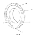
- FIG. 8 is an isometric view of the sliding sleeve (101) of the pressed release bearing FIG. 6 shown. It can be clearly seen that the sliding sleeve (101) next to the central opening only has a radial opening (102) and two axial openings (103), which serve over a circumferential gap (124) for the removal of dirt, moisture or for heat dissipation , It can be clearly seen that the radial openings (102) of the sliding sleeve (101) taper outwards.
- FIGS. 9a and 9b the first and the second sealing element (118, 122) are shown in detail.
- the first sealing element 118 has a stiffener with a metallic core disk 128 and a thickened root 126, which comprises three sealing lips 119a, 119b, 119c.
- the three sealing lips have an X-shape, and different sizes.
- the third sealing lip (119c) is slightly larger in diameter than the first and second sealing lips (119a, 119b).
- the biasing force between the second sealing lip (119b) and the corresponding sealing surface (S3) is realized by a taper of the lip wall thickness (127), as indicated by the arrows.
- the second sealing element (122) has a stiffener with a metallic core disc (128), and a thickened root (126), which comprises two sealing lips (119d, 119e).
- the two sealing lips (119d, 119e) have a V-shape and different sizes.
- the second sealing lip (119e) is slightly larger in diameter than the first sealing lip (119d).
- FIG. 10 an enlarged view of the first sealing element (118) and the capillary gap (123) is shown.
- the first sealing element (118) has a thickened root, which comprises three sealing lips of different sizes.
- the third sealing lip is slightly larger in diameter than the first and the second sealing lip and therefore has more rigidity. Due to the rigid design of this third, larger sealing lip and the root, a radial gap (a) is formed between the third sealing lip and the sealing surface (S3), against which the second sealing lip seals.
- the radial gap (a) remains unaffected both during assembly of the third, larger sealing lip, as well as by the abrasion of the first and / or second sealing lip and has the function of a labyrinth seal.
- the first and the second sealing lip are slightly smaller in diameter than the third, larger sealing lip and act with a certain clamping force radially against a sealing surface of the inner bearing ring.
- the first sealing lip of the sealing surface (S2) on the inner bearing ring is radially opposite, whereas the second sealing lip in their Radial direction is constantly in contact with the centrifugal disc and a contact seal on or with the sealing surface (S3) is formed.
- the first and the second sealing lip can also be provided without contact with a radial gap (a), so that they fulfill the function of a labyrinth seal.
- FIG. 11 shows an enlarged view of the second sealing element (122).
- the second sealing element (122) also has a thickened root (126) which preferably comprises two sealing lips (119d, 119e).
- the two sealing lips (119d, 119e) have different sizes, wherein the second sealing lip (119e) is slightly larger in diameter than the first sealing lip (119d) and therefore has more rigidity.
- Due to the rigid design a radial gap (a) is formed between the second sealing lip (119e) and the sealing surface (S1), against which the first sealing lip (119d) seals.
- the radial gap (a) remains unaffected during the assembly of the second sealing lip (119e) as well as by the abrasion of the first sealing lip (119d).
- the first sealing lip (119d) acts with a certain clamping force radially against the sealing surface (S1) of the inner bearing ring, so that it forms a contact seal on or with the sealing surface (S1).
- the biasing force between the first sealing lip (119d) and the sealing surface (S1) is realized by a defined lip wall thickness (127), a lever arm (L) and a defined angle ( ⁇ ), as indicated by the arrows.
- annular groove (129) is formed as a receiving area for a blocking means (121). This groove (129) is especially important as the space between the two sealing lips (119d, 119e) due to the angle ( ⁇ ) and the short lip seal is not sufficient for a functioning locking means.
Landscapes
- Engineering & Computer Science (AREA)
- General Engineering & Computer Science (AREA)
- Mechanical Engineering (AREA)
- Rolling Contact Bearings (AREA)
- Sealing Of Bearings (AREA)
- Mechanical Operated Clutches (AREA)
Applications Claiming Priority (1)
| Application Number | Priority Date | Filing Date | Title |
|---|---|---|---|
| DE102014111593.7A DE102014111593A1 (de) | 2014-08-13 | 2014-08-13 | Selbstjustierendes Ausrücklager |
Publications (3)
| Publication Number | Publication Date |
|---|---|
| EP2985482A2 true EP2985482A2 (fr) | 2016-02-17 |
| EP2985482A3 EP2985482A3 (fr) | 2016-08-24 |
| EP2985482B1 EP2985482B1 (fr) | 2017-10-18 |
Family
ID=52784933
Family Applications (1)
| Application Number | Title | Priority Date | Filing Date |
|---|---|---|---|
| EP15160118.4A Not-in-force EP2985482B1 (fr) | 2014-08-13 | 2015-03-20 | Butée de débrayage auto-réglable |
Country Status (2)
| Country | Link |
|---|---|
| EP (1) | EP2985482B1 (fr) |
| DE (1) | DE102014111593A1 (fr) |
Cited By (4)
| Publication number | Priority date | Publication date | Assignee | Title |
|---|---|---|---|---|
| WO2018006893A1 (fr) * | 2016-07-06 | 2018-01-11 | Schaeffler Technologies AG & Co. KG | Système de débrayage |
| CN112013042A (zh) * | 2019-05-28 | 2020-12-01 | 舍弗勒技术股份两合公司 | 离合装置 |
| US20220325754A1 (en) * | 2021-04-12 | 2022-10-13 | Aktiebolaget Skf | Support assembly for food applications having an improved inner seal |
| US12241505B2 (en) * | 2022-02-21 | 2025-03-04 | Aktiebolaget Skf | Support assembly for food applications |
Families Citing this family (1)
| Publication number | Priority date | Publication date | Assignee | Title |
|---|---|---|---|---|
| DE102017206235A1 (de) | 2017-04-11 | 2018-10-11 | Zf Friedrichshafen Ag | Ausrücker mit Strömungskanal zur Reinigung |
Citations (5)
| Publication number | Priority date | Publication date | Assignee | Title |
|---|---|---|---|---|
| DE102005026246A1 (de) | 2005-06-08 | 2006-12-14 | Zf Friedrichshafen Ag | Ausrücker für eine Kraftfahrzeugkupplung |
| EP1734271A1 (fr) | 2005-06-13 | 2006-12-20 | Zf Friedrichshafen Ag | Palier à roulement avec un dispositif d'étanchéité protégé |
| EP1734270B1 (fr) | 2005-06-13 | 2007-08-29 | Zf Friedrichshafen Ag | Palier à roulement avec un dispositif d'étanchéité protégé |
| DE102008012815A1 (de) | 2008-03-06 | 2009-09-10 | Zf Friedrichshafen Ag | Ausrückvorrichtung für eine Kraftfahrzeugreibungskupplung mit einer Dichtanordnung für ein selbstjustierendes Ausrücklager |
| DE102012215967A1 (de) | 2012-09-10 | 2014-03-13 | Aktiebolaget Skf | Wälzlager mit integrierter Labyrinthdichtung |
Family Cites Families (5)
| Publication number | Priority date | Publication date | Assignee | Title |
|---|---|---|---|---|
| US4660702A (en) * | 1985-04-24 | 1987-04-28 | Dana Corporation | Clutch release bearing |
| FR2661470B1 (fr) * | 1990-04-27 | 1994-11-25 | Ina Roulements Sa | Roulement de butee, notamment a usage de butee de debrayage. |
| DE19503217A1 (de) * | 1995-02-02 | 1996-08-08 | Schaeffler Waelzlager Kg | Ausrücklager für eine hydraulische Betätigungsvorrichtung einer Trennkupplung |
| US8534926B2 (en) * | 2008-05-27 | 2013-09-17 | Jtekt Corporation | Clutch release bearing |
| DE102010015200A1 (de) * | 2010-04-16 | 2011-10-20 | Schaeffler Technologies Gmbh & Co. Kg | Kasettendichtung |
-
2014
- 2014-08-13 DE DE102014111593.7A patent/DE102014111593A1/de not_active Withdrawn
-
2015
- 2015-03-20 EP EP15160118.4A patent/EP2985482B1/fr not_active Not-in-force
Patent Citations (5)
| Publication number | Priority date | Publication date | Assignee | Title |
|---|---|---|---|---|
| DE102005026246A1 (de) | 2005-06-08 | 2006-12-14 | Zf Friedrichshafen Ag | Ausrücker für eine Kraftfahrzeugkupplung |
| EP1734271A1 (fr) | 2005-06-13 | 2006-12-20 | Zf Friedrichshafen Ag | Palier à roulement avec un dispositif d'étanchéité protégé |
| EP1734270B1 (fr) | 2005-06-13 | 2007-08-29 | Zf Friedrichshafen Ag | Palier à roulement avec un dispositif d'étanchéité protégé |
| DE102008012815A1 (de) | 2008-03-06 | 2009-09-10 | Zf Friedrichshafen Ag | Ausrückvorrichtung für eine Kraftfahrzeugreibungskupplung mit einer Dichtanordnung für ein selbstjustierendes Ausrücklager |
| DE102012215967A1 (de) | 2012-09-10 | 2014-03-13 | Aktiebolaget Skf | Wälzlager mit integrierter Labyrinthdichtung |
Cited By (5)
| Publication number | Priority date | Publication date | Assignee | Title |
|---|---|---|---|---|
| WO2018006893A1 (fr) * | 2016-07-06 | 2018-01-11 | Schaeffler Technologies AG & Co. KG | Système de débrayage |
| CN112013042A (zh) * | 2019-05-28 | 2020-12-01 | 舍弗勒技术股份两合公司 | 离合装置 |
| US20220325754A1 (en) * | 2021-04-12 | 2022-10-13 | Aktiebolaget Skf | Support assembly for food applications having an improved inner seal |
| US11841052B2 (en) * | 2021-04-12 | 2023-12-12 | Aktiebolaget Skf | Support assembly for food applications having an improved inner seal |
| US12241505B2 (en) * | 2022-02-21 | 2025-03-04 | Aktiebolaget Skf | Support assembly for food applications |
Also Published As
| Publication number | Publication date |
|---|---|
| DE102014111593A1 (de) | 2016-02-18 |
| EP2985482A3 (fr) | 2016-08-24 |
| EP2985482B1 (fr) | 2017-10-18 |
Similar Documents
| Publication | Publication Date | Title |
|---|---|---|
| DE60213694T2 (de) | Dichtungssystem für ein Wälzlager | |
| EP2985482B1 (fr) | Butée de débrayage auto-réglable | |
| DE102019205525A1 (de) | Schwenklager mit Dichtanordnung | |
| DE2938393A1 (de) | Labyrinth-dichtungselement und unter verwendung solcher labyrinth-dichtungselemente hergestellte labyrinth-dichtungen | |
| WO2012019803A1 (fr) | Ensemble d'étanchéité pour palier de roulement | |
| WO2010040650A1 (fr) | Système de palier de roue avec joint | |
| DE102006047016A1 (de) | Radlagervorrichtung | |
| DE112017004620T5 (de) | Radlagervorrichtung | |
| DE212014000153U1 (de) | Radhalterungseinheit mit Wälzlager mit einem Dichtungsring | |
| DE102009049466A1 (de) | Ausrücklager einer Reibungskupplung | |
| DE102012219497A1 (de) | Dichtelement für ein Wälzlager | |
| DE102018212108A1 (de) | Reibarme Dichtungsanordnung für eine Radnabeneinheit und Radnabeneinheit, die mit einer solchen Dichtungsanordnung ausgestattet ist | |
| DE102011077729A1 (de) | Wälzlagerdichtung mit Elastomer basierter Vordichtung | |
| DE102020203565A1 (de) | Labyrinthdichtvorrichtung für einen verbesserten Abfluss | |
| DE102022206417A1 (de) | Lagereinheit mit optimierter Verankerung der Dichtvorrichtung | |
| DE102020134674A1 (de) | Lager mit entfernbarem Dichtungsmodul | |
| DE102009015066A1 (de) | Ausrücklager | |
| EP4226061B1 (fr) | Agencement d'étanchéité pour roulements de roue et ensemble roulement de roue doté d'agencement d'étanchéité | |
| DE102019217359A1 (de) | Labyrinthdichtvorrichtung | |
| DE102008052726A1 (de) | Wälzlager mit Dichtelementen | |
| DE102008012815B4 (de) | Ausrückvorrichtung für eine Kraftfahrzeugreibungskupplung mit einer Dichtanordnung für ein selbstjustierendes Ausrücklager | |
| DE102022204801A1 (de) | Dichtvorrichtung für eine Lagereinheit | |
| DE102017129123B4 (de) | Abgedichtetes Wälzlager und Verfahren zum Betrieb eines Wälzlagers | |
| DE102020134673A1 (de) | Wälzlager mit entfernbarem Dichtungsmodul | |
| DE102021210760A1 (de) | Dichtungsvorrichtung für eine Lagereinheit |
Legal Events
| Date | Code | Title | Description |
|---|---|---|---|
| PUAI | Public reference made under article 153(3) epc to a published international application that has entered the european phase |
Free format text: ORIGINAL CODE: 0009012 |
|
| AK | Designated contracting states |
Kind code of ref document: A2 Designated state(s): AL AT BE BG CH CY CZ DE DK EE ES FI FR GB GR HR HU IE IS IT LI LT LU LV MC MK MT NL NO PL PT RO RS SE SI SK SM TR |
|
| AX | Request for extension of the european patent |
Extension state: BA ME |
|
| PUAL | Search report despatched |
Free format text: ORIGINAL CODE: 0009013 |
|
| AK | Designated contracting states |
Kind code of ref document: A3 Designated state(s): AL AT BE BG CH CY CZ DE DK EE ES FI FR GB GR HR HU IE IS IT LI LT LU LV MC MK MT NL NO PL PT RO RS SE SI SK SM TR |
|
| AX | Request for extension of the european patent |
Extension state: BA ME |
|
| RIC1 | Information provided on ipc code assigned before grant |
Ipc: F16C 33/78 20060101ALI20160715BHEP Ipc: F16D 23/14 20060101AFI20160715BHEP |
|
| 17P | Request for examination filed |
Effective date: 20160805 |
|
| RBV | Designated contracting states (corrected) |
Designated state(s): AL AT BE BG CH CY CZ DE DK EE ES FI FR GB GR HR HU IE IS IT LI LT LU LV MC MK MT NL NO PL PT RO RS SE SI SK SM TR |
|
| RIC1 | Information provided on ipc code assigned before grant |
Ipc: F16C 33/78 20060101ALI20170420BHEP Ipc: F16D 23/14 20060101AFI20170420BHEP |
|
| GRAP | Despatch of communication of intention to grant a patent |
Free format text: ORIGINAL CODE: EPIDOSNIGR1 |
|
| INTG | Intention to grant announced |
Effective date: 20170530 |
|
| GRAS | Grant fee paid |
Free format text: ORIGINAL CODE: EPIDOSNIGR3 |
|
| GRAA | (expected) grant |
Free format text: ORIGINAL CODE: 0009210 |
|
| AK | Designated contracting states |
Kind code of ref document: B1 Designated state(s): AL AT BE BG CH CY CZ DE DK EE ES FI FR GB GR HR HU IE IS IT LI LT LU LV MC MK MT NL NO PL PT RO RS SE SI SK SM TR |
|
| REG | Reference to a national code |
Ref country code: GB Ref legal event code: FG4D Free format text: NOT ENGLISH |
|
| REG | Reference to a national code |
Ref country code: CH Ref legal event code: EP |
|
| REG | Reference to a national code |
Ref country code: AT Ref legal event code: REF Ref document number: 938215 Country of ref document: AT Kind code of ref document: T Effective date: 20171115 Ref country code: IE Ref legal event code: FG4D Free format text: LANGUAGE OF EP DOCUMENT: GERMAN |
|
| REG | Reference to a national code |
Ref country code: DE Ref legal event code: R096 Ref document number: 502015002114 Country of ref document: DE |
|
| REG | Reference to a national code |
Ref country code: NL Ref legal event code: MP Effective date: 20171018 |
|
| REG | Reference to a national code |
Ref country code: LT Ref legal event code: MG4D |
|
| REG | Reference to a national code |
Ref country code: FR Ref legal event code: PLFP Year of fee payment: 4 |
|
| PG25 | Lapsed in a contracting state [announced via postgrant information from national office to epo] |
Ref country code: NL Free format text: LAPSE BECAUSE OF FAILURE TO SUBMIT A TRANSLATION OF THE DESCRIPTION OR TO PAY THE FEE WITHIN THE PRESCRIBED TIME-LIMIT Effective date: 20171018 |
|
| PG25 | Lapsed in a contracting state [announced via postgrant information from national office to epo] |
Ref country code: NO Free format text: LAPSE BECAUSE OF FAILURE TO SUBMIT A TRANSLATION OF THE DESCRIPTION OR TO PAY THE FEE WITHIN THE PRESCRIBED TIME-LIMIT Effective date: 20180118 Ref country code: LT Free format text: LAPSE BECAUSE OF FAILURE TO SUBMIT A TRANSLATION OF THE DESCRIPTION OR TO PAY THE FEE WITHIN THE PRESCRIBED TIME-LIMIT Effective date: 20171018 Ref country code: FI Free format text: LAPSE BECAUSE OF FAILURE TO SUBMIT A TRANSLATION OF THE DESCRIPTION OR TO PAY THE FEE WITHIN THE PRESCRIBED TIME-LIMIT Effective date: 20171018 Ref country code: SE Free format text: LAPSE BECAUSE OF FAILURE TO SUBMIT A TRANSLATION OF THE DESCRIPTION OR TO PAY THE FEE WITHIN THE PRESCRIBED TIME-LIMIT Effective date: 20171018 Ref country code: ES Free format text: LAPSE BECAUSE OF FAILURE TO SUBMIT A TRANSLATION OF THE DESCRIPTION OR TO PAY THE FEE WITHIN THE PRESCRIBED TIME-LIMIT Effective date: 20171018 |
|
| PGFP | Annual fee paid to national office [announced via postgrant information from national office to epo] |
Ref country code: LU Payment date: 20180322 Year of fee payment: 4 |
|
| PG25 | Lapsed in a contracting state [announced via postgrant information from national office to epo] |
Ref country code: LV Free format text: LAPSE BECAUSE OF FAILURE TO SUBMIT A TRANSLATION OF THE DESCRIPTION OR TO PAY THE FEE WITHIN THE PRESCRIBED TIME-LIMIT Effective date: 20171018 Ref country code: IS Free format text: LAPSE BECAUSE OF FAILURE TO SUBMIT A TRANSLATION OF THE DESCRIPTION OR TO PAY THE FEE WITHIN THE PRESCRIBED TIME-LIMIT Effective date: 20180218 Ref country code: RS Free format text: LAPSE BECAUSE OF FAILURE TO SUBMIT A TRANSLATION OF THE DESCRIPTION OR TO PAY THE FEE WITHIN THE PRESCRIBED TIME-LIMIT Effective date: 20171018 Ref country code: BG Free format text: LAPSE BECAUSE OF FAILURE TO SUBMIT A TRANSLATION OF THE DESCRIPTION OR TO PAY THE FEE WITHIN THE PRESCRIBED TIME-LIMIT Effective date: 20180118 Ref country code: GR Free format text: LAPSE BECAUSE OF FAILURE TO SUBMIT A TRANSLATION OF THE DESCRIPTION OR TO PAY THE FEE WITHIN THE PRESCRIBED TIME-LIMIT Effective date: 20180119 Ref country code: HR Free format text: LAPSE BECAUSE OF FAILURE TO SUBMIT A TRANSLATION OF THE DESCRIPTION OR TO PAY THE FEE WITHIN THE PRESCRIBED TIME-LIMIT Effective date: 20171018 |
|
| PGFP | Annual fee paid to national office [announced via postgrant information from national office to epo] |
Ref country code: IE Payment date: 20180326 Year of fee payment: 4 Ref country code: MC Payment date: 20180321 Year of fee payment: 4 |
|
| REG | Reference to a national code |
Ref country code: DE Ref legal event code: R097 Ref document number: 502015002114 Country of ref document: DE |
|
| PG25 | Lapsed in a contracting state [announced via postgrant information from national office to epo] |
Ref country code: CZ Free format text: LAPSE BECAUSE OF FAILURE TO SUBMIT A TRANSLATION OF THE DESCRIPTION OR TO PAY THE FEE WITHIN THE PRESCRIBED TIME-LIMIT Effective date: 20171018 Ref country code: EE Free format text: LAPSE BECAUSE OF FAILURE TO SUBMIT A TRANSLATION OF THE DESCRIPTION OR TO PAY THE FEE WITHIN THE PRESCRIBED TIME-LIMIT Effective date: 20171018 Ref country code: DK Free format text: LAPSE BECAUSE OF FAILURE TO SUBMIT A TRANSLATION OF THE DESCRIPTION OR TO PAY THE FEE WITHIN THE PRESCRIBED TIME-LIMIT Effective date: 20171018 Ref country code: SK Free format text: LAPSE BECAUSE OF FAILURE TO SUBMIT A TRANSLATION OF THE DESCRIPTION OR TO PAY THE FEE WITHIN THE PRESCRIBED TIME-LIMIT Effective date: 20171018 |
|
| PLBE | No opposition filed within time limit |
Free format text: ORIGINAL CODE: 0009261 |
|
| STAA | Information on the status of an ep patent application or granted ep patent |
Free format text: STATUS: NO OPPOSITION FILED WITHIN TIME LIMIT |
|
| PG25 | Lapsed in a contracting state [announced via postgrant information from national office to epo] |
Ref country code: IT Free format text: LAPSE BECAUSE OF FAILURE TO SUBMIT A TRANSLATION OF THE DESCRIPTION OR TO PAY THE FEE WITHIN THE PRESCRIBED TIME-LIMIT Effective date: 20171018 Ref country code: RO Free format text: LAPSE BECAUSE OF FAILURE TO SUBMIT A TRANSLATION OF THE DESCRIPTION OR TO PAY THE FEE WITHIN THE PRESCRIBED TIME-LIMIT Effective date: 20171018 Ref country code: PL Free format text: LAPSE BECAUSE OF FAILURE TO SUBMIT A TRANSLATION OF THE DESCRIPTION OR TO PAY THE FEE WITHIN THE PRESCRIBED TIME-LIMIT Effective date: 20171018 Ref country code: SM Free format text: LAPSE BECAUSE OF FAILURE TO SUBMIT A TRANSLATION OF THE DESCRIPTION OR TO PAY THE FEE WITHIN THE PRESCRIBED TIME-LIMIT Effective date: 20171018 |
|
| 26N | No opposition filed |
Effective date: 20180719 |
|
| PG25 | Lapsed in a contracting state [announced via postgrant information from national office to epo] |
Ref country code: MT Free format text: LAPSE BECAUSE OF FAILURE TO SUBMIT A TRANSLATION OF THE DESCRIPTION OR TO PAY THE FEE WITHIN THE PRESCRIBED TIME-LIMIT Effective date: 20171018 |
|
| PG25 | Lapsed in a contracting state [announced via postgrant information from national office to epo] |
Ref country code: SI Free format text: LAPSE BECAUSE OF FAILURE TO SUBMIT A TRANSLATION OF THE DESCRIPTION OR TO PAY THE FEE WITHIN THE PRESCRIBED TIME-LIMIT Effective date: 20171018 |
|
| PG25 | Lapsed in a contracting state [announced via postgrant information from national office to epo] |
Ref country code: MC Free format text: LAPSE BECAUSE OF NON-PAYMENT OF DUE FEES Effective date: 20190401 |
|
| PG25 | Lapsed in a contracting state [announced via postgrant information from national office to epo] |
Ref country code: LU Free format text: LAPSE BECAUSE OF NON-PAYMENT OF DUE FEES Effective date: 20190320 |
|
| PG25 | Lapsed in a contracting state [announced via postgrant information from national office to epo] |
Ref country code: IE Free format text: LAPSE BECAUSE OF NON-PAYMENT OF DUE FEES Effective date: 20190320 |
|
| PG25 | Lapsed in a contracting state [announced via postgrant information from national office to epo] |
Ref country code: TR Free format text: LAPSE BECAUSE OF FAILURE TO SUBMIT A TRANSLATION OF THE DESCRIPTION OR TO PAY THE FEE WITHIN THE PRESCRIBED TIME-LIMIT Effective date: 20171018 |
|
| PGFP | Annual fee paid to national office [announced via postgrant information from national office to epo] |
Ref country code: AT Payment date: 20200319 Year of fee payment: 6 |
|
| PG25 | Lapsed in a contracting state [announced via postgrant information from national office to epo] |
Ref country code: PT Free format text: LAPSE BECAUSE OF FAILURE TO SUBMIT A TRANSLATION OF THE DESCRIPTION OR TO PAY THE FEE WITHIN THE PRESCRIBED TIME-LIMIT Effective date: 20171018 |
|
| PGFP | Annual fee paid to national office [announced via postgrant information from national office to epo] |
Ref country code: CH Payment date: 20200325 Year of fee payment: 6 |
|
| PG25 | Lapsed in a contracting state [announced via postgrant information from national office to epo] |
Ref country code: CY Free format text: LAPSE BECAUSE OF FAILURE TO SUBMIT A TRANSLATION OF THE DESCRIPTION OR TO PAY THE FEE WITHIN THE PRESCRIBED TIME-LIMIT Effective date: 20171018 Ref country code: MK Free format text: LAPSE BECAUSE OF NON-PAYMENT OF DUE FEES Effective date: 20171018 Ref country code: HU Free format text: LAPSE BECAUSE OF FAILURE TO SUBMIT A TRANSLATION OF THE DESCRIPTION OR TO PAY THE FEE WITHIN THE PRESCRIBED TIME-LIMIT; INVALID AB INITIO Effective date: 20150320 |
|
| PG25 | Lapsed in a contracting state [announced via postgrant information from national office to epo] |
Ref country code: AL Free format text: LAPSE BECAUSE OF FAILURE TO SUBMIT A TRANSLATION OF THE DESCRIPTION OR TO PAY THE FEE WITHIN THE PRESCRIBED TIME-LIMIT Effective date: 20171018 |
|
| PGFP | Annual fee paid to national office [announced via postgrant information from national office to epo] |
Ref country code: BE Payment date: 20200622 Year of fee payment: 6 |
|
| PGFP | Annual fee paid to national office [announced via postgrant information from national office to epo] |
Ref country code: FR Payment date: 20210331 Year of fee payment: 7 |
|
| PGFP | Annual fee paid to national office [announced via postgrant information from national office to epo] |
Ref country code: GB Payment date: 20210422 Year of fee payment: 7 |
|
| REG | Reference to a national code |
Ref country code: CH Ref legal event code: PL |
|
| REG | Reference to a national code |
Ref country code: AT Ref legal event code: MM01 Ref document number: 938215 Country of ref document: AT Kind code of ref document: T Effective date: 20210320 |
|
| REG | Reference to a national code |
Ref country code: BE Ref legal event code: MM Effective date: 20210331 |
|
| PG25 | Lapsed in a contracting state [announced via postgrant information from national office to epo] |
Ref country code: LI Free format text: LAPSE BECAUSE OF NON-PAYMENT OF DUE FEES Effective date: 20210331 Ref country code: CH Free format text: LAPSE BECAUSE OF NON-PAYMENT OF DUE FEES Effective date: 20210331 Ref country code: AT Free format text: LAPSE BECAUSE OF NON-PAYMENT OF DUE FEES Effective date: 20210320 |
|
| PG25 | Lapsed in a contracting state [announced via postgrant information from national office to epo] |
Ref country code: BE Free format text: LAPSE BECAUSE OF NON-PAYMENT OF DUE FEES Effective date: 20210331 |
|
| PGFP | Annual fee paid to national office [announced via postgrant information from national office to epo] |
Ref country code: DE Payment date: 20220523 Year of fee payment: 8 |
|
| GBPC | Gb: european patent ceased through non-payment of renewal fee |
Effective date: 20220320 |
|
| PG25 | Lapsed in a contracting state [announced via postgrant information from national office to epo] |
Ref country code: GB Free format text: LAPSE BECAUSE OF NON-PAYMENT OF DUE FEES Effective date: 20220320 Ref country code: FR Free format text: LAPSE BECAUSE OF NON-PAYMENT OF DUE FEES Effective date: 20220331 |
|
| REG | Reference to a national code |
Ref country code: DE Ref legal event code: R119 Ref document number: 502015002114 Country of ref document: DE |
|
| PG25 | Lapsed in a contracting state [announced via postgrant information from national office to epo] |
Ref country code: DE Free format text: LAPSE BECAUSE OF NON-PAYMENT OF DUE FEES Effective date: 20231003 |