EP2985482A2 - Self-aligned release bearing - Google Patents
Self-aligned release bearing Download PDFInfo
- Publication number
- EP2985482A2 EP2985482A2 EP15160118.4A EP15160118A EP2985482A2 EP 2985482 A2 EP2985482 A2 EP 2985482A2 EP 15160118 A EP15160118 A EP 15160118A EP 2985482 A2 EP2985482 A2 EP 2985482A2
- Authority
- EP
- European Patent Office
- Prior art keywords
- sealing
- bearing ring
- sliding sleeve
- radial
- release
- Prior art date
- Legal status (The legal status is an assumption and is not a legal conclusion. Google has not performed a legal analysis and makes no representation as to the accuracy of the status listed.)
- Granted
Links
- 238000007789 sealing Methods 0.000 claims abstract description 257
- 238000005096 rolling process Methods 0.000 claims abstract description 20
- 230000000903 blocking effect Effects 0.000 claims description 24
- 239000000314 lubricant Substances 0.000 claims description 13
- 239000004519 grease Substances 0.000 claims description 6
- 239000000356 contaminant Substances 0.000 claims description 5
- 239000002245 particle Substances 0.000 description 18
- 238000005299 abrasion Methods 0.000 description 10
- 239000002981 blocking agent Substances 0.000 description 10
- 239000000428 dust Substances 0.000 description 9
- 238000013461 design Methods 0.000 description 8
- 238000012423 maintenance Methods 0.000 description 7
- 230000008439 repair process Effects 0.000 description 6
- 230000002093 peripheral effect Effects 0.000 description 5
- 230000008901 benefit Effects 0.000 description 4
- 230000000994 depressogenic effect Effects 0.000 description 4
- 230000000694 effects Effects 0.000 description 4
- 230000000149 penetrating effect Effects 0.000 description 4
- 230000035515 penetration Effects 0.000 description 4
- 239000000126 substance Substances 0.000 description 4
- 238000011109 contamination Methods 0.000 description 3
- 230000008878 coupling Effects 0.000 description 3
- 238000010168 coupling process Methods 0.000 description 3
- 238000005859 coupling reaction Methods 0.000 description 3
- 229920001971 elastomer Polymers 0.000 description 3
- 239000000806 elastomer Substances 0.000 description 3
- 230000017525 heat dissipation Effects 0.000 description 3
- 238000000034 method Methods 0.000 description 3
- 230000008569 process Effects 0.000 description 3
- 230000009467 reduction Effects 0.000 description 3
- 239000007787 solid Substances 0.000 description 3
- 239000003351 stiffener Substances 0.000 description 3
- 229910000831 Steel Inorganic materials 0.000 description 2
- 239000000853 adhesive Substances 0.000 description 2
- 230000001070 adhesive effect Effects 0.000 description 2
- 239000003570 air Substances 0.000 description 2
- 239000012080 ambient air Substances 0.000 description 2
- 230000004888 barrier function Effects 0.000 description 2
- 230000005540 biological transmission Effects 0.000 description 2
- 238000010276 construction Methods 0.000 description 2
- 230000008021 deposition Effects 0.000 description 2
- 239000000463 material Substances 0.000 description 2
- 229910001220 stainless steel Inorganic materials 0.000 description 2
- 239000010935 stainless steel Substances 0.000 description 2
- 239000010959 steel Substances 0.000 description 2
- 230000002411 adverse Effects 0.000 description 1
- 239000012754 barrier agent Substances 0.000 description 1
- 238000011161 development Methods 0.000 description 1
- 230000018109 developmental process Effects 0.000 description 1
- 238000007599 discharging Methods 0.000 description 1
- 230000007613 environmental effect Effects 0.000 description 1
- 239000007788 liquid Substances 0.000 description 1
- 230000005923 long-lasting effect Effects 0.000 description 1
- 238000004519 manufacturing process Methods 0.000 description 1
- 238000005065 mining Methods 0.000 description 1
- 239000000203 mixture Substances 0.000 description 1
- 238000003860 storage Methods 0.000 description 1
- 230000008961 swelling Effects 0.000 description 1
- 238000012546 transfer Methods 0.000 description 1
- 238000011144 upstream manufacturing Methods 0.000 description 1
- XLYOFNOQVPJJNP-UHFFFAOYSA-N water Substances O XLYOFNOQVPJJNP-UHFFFAOYSA-N 0.000 description 1
Images


Classifications
-
- F—MECHANICAL ENGINEERING; LIGHTING; HEATING; WEAPONS; BLASTING
- F16—ENGINEERING ELEMENTS AND UNITS; GENERAL MEASURES FOR PRODUCING AND MAINTAINING EFFECTIVE FUNCTIONING OF MACHINES OR INSTALLATIONS; THERMAL INSULATION IN GENERAL
- F16D—COUPLINGS FOR TRANSMITTING ROTATION; CLUTCHES; BRAKES
- F16D23/00—Details of mechanically-actuated clutches not specific for one distinct type
- F16D23/12—Mechanical clutch-actuating mechanisms arranged outside the clutch as such
- F16D23/14—Clutch-actuating sleeves or bearings; Actuating members directly connected to clutch-actuating sleeves or bearings
- F16D23/148—Guide-sleeve receiving the clutch release bearing
-
- F—MECHANICAL ENGINEERING; LIGHTING; HEATING; WEAPONS; BLASTING
- F16—ENGINEERING ELEMENTS AND UNITS; GENERAL MEASURES FOR PRODUCING AND MAINTAINING EFFECTIVE FUNCTIONING OF MACHINES OR INSTALLATIONS; THERMAL INSULATION IN GENERAL
- F16C—SHAFTS; FLEXIBLE SHAFTS; ELEMENTS OR CRANKSHAFT MECHANISMS; ROTARY BODIES OTHER THAN GEARING ELEMENTS; BEARINGS
- F16C33/00—Parts of bearings; Special methods for making bearings or parts thereof
- F16C33/72—Sealings
- F16C33/76—Sealings of ball or roller bearings
- F16C33/78—Sealings of ball or roller bearings with a diaphragm, disc, or ring, with or without resilient members
- F16C33/7816—Details of the sealing or parts thereof, e.g. geometry, material
- F16C33/782—Details of the sealing or parts thereof, e.g. geometry, material of the sealing region
-
- F—MECHANICAL ENGINEERING; LIGHTING; HEATING; WEAPONS; BLASTING
- F16—ENGINEERING ELEMENTS AND UNITS; GENERAL MEASURES FOR PRODUCING AND MAINTAINING EFFECTIVE FUNCTIONING OF MACHINES OR INSTALLATIONS; THERMAL INSULATION IN GENERAL
- F16C—SHAFTS; FLEXIBLE SHAFTS; ELEMENTS OR CRANKSHAFT MECHANISMS; ROTARY BODIES OTHER THAN GEARING ELEMENTS; BEARINGS
- F16C33/00—Parts of bearings; Special methods for making bearings or parts thereof
- F16C33/72—Sealings
- F16C33/76—Sealings of ball or roller bearings
- F16C33/78—Sealings of ball or roller bearings with a diaphragm, disc, or ring, with or without resilient members
- F16C33/784—Sealings of ball or roller bearings with a diaphragm, disc, or ring, with or without resilient members mounted to a groove in the inner surface of the outer race and extending toward the inner race
- F16C33/7843—Sealings of ball or roller bearings with a diaphragm, disc, or ring, with or without resilient members mounted to a groove in the inner surface of the outer race and extending toward the inner race with a single annular sealing disc
- F16C33/7853—Sealings of ball or roller bearings with a diaphragm, disc, or ring, with or without resilient members mounted to a groove in the inner surface of the outer race and extending toward the inner race with a single annular sealing disc with one or more sealing lips to contact the inner race
-
- F—MECHANICAL ENGINEERING; LIGHTING; HEATING; WEAPONS; BLASTING
- F16—ENGINEERING ELEMENTS AND UNITS; GENERAL MEASURES FOR PRODUCING AND MAINTAINING EFFECTIVE FUNCTIONING OF MACHINES OR INSTALLATIONS; THERMAL INSULATION IN GENERAL
- F16C—SHAFTS; FLEXIBLE SHAFTS; ELEMENTS OR CRANKSHAFT MECHANISMS; ROTARY BODIES OTHER THAN GEARING ELEMENTS; BEARINGS
- F16C33/00—Parts of bearings; Special methods for making bearings or parts thereof
- F16C33/72—Sealings
- F16C33/76—Sealings of ball or roller bearings
- F16C33/78—Sealings of ball or roller bearings with a diaphragm, disc, or ring, with or without resilient members
- F16C33/784—Sealings of ball or roller bearings with a diaphragm, disc, or ring, with or without resilient members mounted to a groove in the inner surface of the outer race and extending toward the inner race
- F16C33/7859—Sealings of ball or roller bearings with a diaphragm, disc, or ring, with or without resilient members mounted to a groove in the inner surface of the outer race and extending toward the inner race with a further sealing element
- F16C33/7863—Sealings of ball or roller bearings with a diaphragm, disc, or ring, with or without resilient members mounted to a groove in the inner surface of the outer race and extending toward the inner race with a further sealing element mounted to the inner race, e.g. a flinger to use centrifugal effect
-
- F—MECHANICAL ENGINEERING; LIGHTING; HEATING; WEAPONS; BLASTING
- F16—ENGINEERING ELEMENTS AND UNITS; GENERAL MEASURES FOR PRODUCING AND MAINTAINING EFFECTIVE FUNCTIONING OF MACHINES OR INSTALLATIONS; THERMAL INSULATION IN GENERAL
- F16C—SHAFTS; FLEXIBLE SHAFTS; ELEMENTS OR CRANKSHAFT MECHANISMS; ROTARY BODIES OTHER THAN GEARING ELEMENTS; BEARINGS
- F16C33/00—Parts of bearings; Special methods for making bearings or parts thereof
- F16C33/72—Sealings
- F16C33/76—Sealings of ball or roller bearings
- F16C33/78—Sealings of ball or roller bearings with a diaphragm, disc, or ring, with or without resilient members
- F16C33/784—Sealings of ball or roller bearings with a diaphragm, disc, or ring, with or without resilient members mounted to a groove in the inner surface of the outer race and extending toward the inner race
- F16C33/7859—Sealings of ball or roller bearings with a diaphragm, disc, or ring, with or without resilient members mounted to a groove in the inner surface of the outer race and extending toward the inner race with a further sealing element
- F16C33/7866—Sealings of ball or roller bearings with a diaphragm, disc, or ring, with or without resilient members mounted to a groove in the inner surface of the outer race and extending toward the inner race with a further sealing element with sealing lips
-
- F—MECHANICAL ENGINEERING; LIGHTING; HEATING; WEAPONS; BLASTING
- F16—ENGINEERING ELEMENTS AND UNITS; GENERAL MEASURES FOR PRODUCING AND MAINTAINING EFFECTIVE FUNCTIONING OF MACHINES OR INSTALLATIONS; THERMAL INSULATION IN GENERAL
- F16C—SHAFTS; FLEXIBLE SHAFTS; ELEMENTS OR CRANKSHAFT MECHANISMS; ROTARY BODIES OTHER THAN GEARING ELEMENTS; BEARINGS
- F16C33/00—Parts of bearings; Special methods for making bearings or parts thereof
- F16C33/72—Sealings
- F16C33/76—Sealings of ball or roller bearings
- F16C33/78—Sealings of ball or roller bearings with a diaphragm, disc, or ring, with or without resilient members
- F16C33/7886—Sealings of ball or roller bearings with a diaphragm, disc, or ring, with or without resilient members mounted outside the gap between the inner and outer races, e.g. sealing rings mounted to an end face or outer surface of a race
-
- F—MECHANICAL ENGINEERING; LIGHTING; HEATING; WEAPONS; BLASTING
- F16—ENGINEERING ELEMENTS AND UNITS; GENERAL MEASURES FOR PRODUCING AND MAINTAINING EFFECTIVE FUNCTIONING OF MACHINES OR INSTALLATIONS; THERMAL INSULATION IN GENERAL
- F16D—COUPLINGS FOR TRANSMITTING ROTATION; CLUTCHES; BRAKES
- F16D23/00—Details of mechanically-actuated clutches not specific for one distinct type
- F16D23/12—Mechanical clutch-actuating mechanisms arranged outside the clutch as such
- F16D23/14—Clutch-actuating sleeves or bearings; Actuating members directly connected to clutch-actuating sleeves or bearings
-
- F—MECHANICAL ENGINEERING; LIGHTING; HEATING; WEAPONS; BLASTING
- F16—ENGINEERING ELEMENTS AND UNITS; GENERAL MEASURES FOR PRODUCING AND MAINTAINING EFFECTIVE FUNCTIONING OF MACHINES OR INSTALLATIONS; THERMAL INSULATION IN GENERAL
- F16C—SHAFTS; FLEXIBLE SHAFTS; ELEMENTS OR CRANKSHAFT MECHANISMS; ROTARY BODIES OTHER THAN GEARING ELEMENTS; BEARINGS
- F16C19/00—Bearings with rolling contact, for exclusively rotary movement
- F16C19/02—Bearings with rolling contact, for exclusively rotary movement with bearing balls essentially of the same size in one or more circular rows
- F16C19/04—Bearings with rolling contact, for exclusively rotary movement with bearing balls essentially of the same size in one or more circular rows for radial load mainly
- F16C19/06—Bearings with rolling contact, for exclusively rotary movement with bearing balls essentially of the same size in one or more circular rows for radial load mainly with a single row or balls
-
- F—MECHANICAL ENGINEERING; LIGHTING; HEATING; WEAPONS; BLASTING
- F16—ENGINEERING ELEMENTS AND UNITS; GENERAL MEASURES FOR PRODUCING AND MAINTAINING EFFECTIVE FUNCTIONING OF MACHINES OR INSTALLATIONS; THERMAL INSULATION IN GENERAL
- F16C—SHAFTS; FLEXIBLE SHAFTS; ELEMENTS OR CRANKSHAFT MECHANISMS; ROTARY BODIES OTHER THAN GEARING ELEMENTS; BEARINGS
- F16C2361/00—Apparatus or articles in engineering in general
- F16C2361/43—Clutches, e.g. disengaging bearing
-
- F—MECHANICAL ENGINEERING; LIGHTING; HEATING; WEAPONS; BLASTING
- F16—ENGINEERING ELEMENTS AND UNITS; GENERAL MEASURES FOR PRODUCING AND MAINTAINING EFFECTIVE FUNCTIONING OF MACHINES OR INSTALLATIONS; THERMAL INSULATION IN GENERAL
- F16D—COUPLINGS FOR TRANSMITTING ROTATION; CLUTCHES; BRAKES
- F16D2300/00—Special features for couplings or clutches
- F16D2300/08—Details or arrangements of sealings not provided for in group F16D3/84
Definitions
- the invention relates to a release device for a friction clutch of a motor vehicle, comprising a guide tube, a sliding sleeve, which is axially displaceable on the guide tube and at least one radial and axial opening comprises a holding portion to which a retaining plate is attached, which a self-aligning release bearing to a Presses the flange of the sliding sleeve and at least one radial opening, the release bearing, which rotatably to the sliding sleeve arranged outer bearing ring, between the outer and an inner bearing ring arranged rolling elements and a circumferential inner bearing ring, wherein the inner bearing ring with an actuating element of the friction clutch in An operative connection is, a slinger, which is connected to the inner bearing ring and a first and second sealing element, which are connected to the outer bearing ring.
- a friction clutch is mainly installed in motor vehicles to separate and close the power flow between an engine and a transmission when starting or changing gears. It can be operated mechanically, hydraulically or electrically and consists of a clutch disc, which is pressed by one or more springs with a pressure plate to the flywheel of the engine. Upon actuation of the clutch, the spring pressure is overcome by the release lever, so that the disc can rotate freely and the clutch is disconnected.
- the friction clutch is switchable during operation and uses the frictional resistance between two plates to transfer forces from one plate to another. Therefore, the clutch performs a large friction work, resulting in a strong mechanical abrasion of the clutch, which is determined by the operating conditions and therefore can be influenced only insignificantly. Added to this is the thermal load on the coupling.
- Release devices for actuating a friction clutch of a motor vehicle comprise as a main component a release bearing designed as a roller bearing.
- the release bearing is used in the drive train of motor vehicles.
- a careful sealing of the bearing interior is required.
- the rolling elements are in contact with the raceways of the bearing in force-transmitting rolling contact.
- contacting and / or contact-free sealing arrangements are provided directly on the roller bearing or on components adjacent to the bearing.
- Such sealing arrangements are usually elastomer and / or labyrinth seals, which may additionally comprise receiving areas filled with a blocking agent.
- the main function of the seal assembly is on the one hand the avoidance of lubricant leakage and on the other hand the reduction of dirt or moisture ingress into the bearing interior. In contact seals, however, wear is inevitable.
- the bearings of the coupling are contaminated by moisture, suspended solids and other dirt particles from the ambient air. This is especially true for rolling bearing seals in motor vehicles, which are exposed to extremely large amounts of dust and dirt, such as This is the case in road and mining, as well as in agriculture and forestry.
- the dusts and suspended matter contained in the ambient air easily enter the bell housing and are transported there with the circulating air directly to the coupling release device. There they are stored together with the already present clutch wear, preferably on the sealing elements of the release bearing. Due to the swelling axial load of a release bearing and the wear-promoting aggressiveness of the dusts and suspended matter, there is a continuous reduction in the effectiveness of the sealing systems of the camp. This means that they soon no longer work, which can ultimately lead to failure of the release bearing and thus the entire friction clutch.
- the blocking means can be pushed out step by step in a radial self-adjustment of the release bearing from the receiving area.
- the barrier layer can also dissolve from one of the components, which allows the entry of dusts and suspended matter.
- the blocking agent can be attacked directly by the dusts and suspended particles that collect in and on the release bearing become. This negatively affects the blocking agent property, so that the blocking agent gradually becomes the main disturbance factor for the main seal.
- the release bearing has a cover element.
- the cover element is fixed to the outer, rotationally fixed bearing ring and covers a located between the bearing rings access area of the bearing interior.
- a receiving area filled with a blocking means is formed between the cover element and the circumferential bearing ring.
- the locking means acts as an upstream seal and blocks the entry of dirt into the release bearing. Due to the arrangement of the cover element, the shape of the receiving area filled with blocking means is not influenced during the self-adjustment of the release bearing. In this way, the dust and suspended load of the sealing system is greatly reduced.
- the blocking agent is attacked directly by the coarse dusts and suspended matter, so that the blocking agent property is adversely affected. Furthermore, due to the undefined shape of the receiving area and the centrifugal force effect, the blocking means will move radially outwards along the inner side of the cover element, so that the amount of blocking means is reduced continuously. This gradually allows the entry of foreign particles into the release bearing. In this way, therefore, only time is gained until the wear-related failure of the release bearing.
- a release device for a friction clutch of a motor vehicle with a self-aligning release bearing which is reliable and long-lasting protection against contamination, such as suspended matter, dusts and moisture ingress. It is therefore of great importance to seal a release bearing so well that the amount of contaminant is local, i. in the area of the bearing interior, maximum is reduced and that the seal is subject to the lowest possible own wear. Based on this point, the invention therefore has the task of providing bearings whose sealing elements ensure longer life of the release bearing and thus lower downtime and repair or maintenance costs even under extreme external and wear-promoting conditions.
- Another aspect of extending the life of the release bearing is to remove the heat generated in the bearing to the outside, since the heat dissipated negatively affects the life of the bearing.
- this problem is not addressed.
- These are, however, strongly encapsulated, for example by a sliding sleeve, which leads to a reduction of heat dissipation. Therefore, it has become the invention further set the task to cool the rolling bearing targeted and dissipate the excess heat in the environment.
- the object of the invention is therefore to provide a release device for a friction clutch of a motor vehicle whose failure-related repair and maintenance times are reduced to a minimum by the release bearing is reliably and durable protected against penetrating into the bearing interior contaminants and leaking lubricants.
- the heat generated at the release bearing is reliably dissipated, which additionally increases the lifetime of the bearing.
- a disengaging device for a friction clutch of a motor vehicle which is a guide tube, an axially displaceable on the guide tube sliding sleeve, a holding portion to which a retaining plate is attached, a self-aligning release bearing, a centrifugal disc and a first and second sealing element comprises.
- the release device can be built in pulled or pressed construction.
- sliding sleeve is understood to be an axially displaceable sleeve on the guide tube.
- the sliding sleeve is made of any material, but this is not essential in the invention. This is in addition to its central opening provided with further openings, which openings are functional openings for increasing the air circulation and / or the removal of dirt or heat. These are arranged on the outer edge of the sliding sleeve.
- the openings are radially and axially aligned.
- the sliding sleeve comprises at least one radial and axial opening.
- the radial and axial openings are arranged at the level of the release bearing.
- the sliding sleeve for a pulled release bearing comprises at least two radial openings and an axial opening.
- the sliding sleeve preferably comprises a radial opening and at least two axial openings.
- the radial openings are preferably configured to taper outwardly so as to ensure that debris is conducted outwardly of the release bearing due to its own weight and / or heat. At the same time due to the special design of the openings and the centrifugal force flow of the centrifugal disc thus the dirt entry is reduced in the release bearing.
- the axial opening is designed so that it tapers to the outside.
- heat is mainly discharged through an outwardly narrowing, funnel-shaped opening from the release bearing.
- it can not be prevented that dirt is transported away via the axial opening from the release bearing to the outside.
- the deduced amount of dirt is negligible, as this is preferably discharged through the radial openings due to its own weight and the centrifugal force.
- the sliding sleeve can also have an introduced groove, which facilitates the mounting of the retaining plate and ensures that any dirt entering the bearing is immediately removed from the bearing.
- holding portion refers to a portion to which a retaining plate is attached, which presses a self-aligning release bearing on a flange of the sliding sleeve. Between this flange and the outer bearing ring of the release bearing is a spring element.
- the flange is a radial flange.
- the holding plate is rolled on the outer peripheral surface of the holding portion and extends under the influence of a radial adjusting gap axially over the release bearing.
- the holding plate engages on the end face remote from the holding area of the radially outer, non-rotatable bearing ring to the release bearing.
- the retaining plate comprises at least one radial opening, which is arranged on the outer edge of the retaining plate.
- dirt and / or heat is conducted to the outside from the release bearing by means of the centrifugal force generated by the centrifugal disc.
- the dirt is also directed to the outside due to its own weight. This ensures that the entry of dirt into the release bearing is significantly reduced or avoided.
- At least one further such radial opening can also be attached to another location of the release device.
- release bearing is understood to mean a disengaging or roller bearing, which comprises an outer bearing ring, arranged rotatably relative to a sliding sleeve, between the outer and an inner bearing ring arranged rolling elements and a circumferential inner bearing ring.
- the inner bearing ring can be extended beyond the release bearing by means of an axial extension and is in operative connection with an actuating element of the friction clutch.
- the release bearing is configured self-adjusting, i. it centers itself in radial alignment on the crankshaft. The expert knows to realize this.
- the term "slinger” refers to a permanently installed, annular disc which is connected to the inner bearing ring.
- the centrifugal disc is fixed to the side facing away from the rolling body circumferential surface of the rotating inner bearing ring and encloses one of its end faces.
- the centrifugal disc is designed such that it with the flange of the Sliding sleeve forms a circumferential gap through which dirt and heat are dissipated.
- the sling can be made of any material and have different shapes.
- the centrifugal disc preferably generates a concentric flow within the disengaging device, which is deflected radially outwards by the centrifugal force. With this flow thus heat and dirt is carried away or entrained.
- the flow causes contaminants from the release bearing via the radial opening of the sliding sleeve and / or the radial opening of the retaining plate to be transported to the outside or entrained.
- the flow tears heat from the release bearing via the radial and / or axial opening of the sliding sleeve and / or the radial opening of the retaining plate.
- sealing element refers to a means for sealing the release bearing.
- the release device comprises two sealing elements.
- the first sealing element seals the Wälzoresraum to the inside of the release bearing, whereas the second sealing element seals the WälzMechraum to the outside of the release bearing.
- Both sealing elements are connected to the outer bearing ring and preferably form a labyrinth seal.
- the sealing elements are vulcanized and fixed.
- the first sealing element with the inner bearing ring on one side and the centrifugal disk on the other side preferably form a sealing structure which reliably protects the release bearing against the penetration of foreign particles or moisture.
- the protection of the release bearing is based on the fact that by means of the centrifugal force flow generated by the centrifugal disc and the own weight of foreign particles, suspended solids and dusts, they are transported to the outside via the radial and / or axial opening of the sliding sleeve. In this way, a high shielding of the release bearing is already achieved.
- the capillary gap is realized in such a way that its bounding surfaces, i. the circumferential inner bearing ring and the fixed outer bearing ring, just do not touch and this is not affected by the adjustment process of the release bearing.
- the capillary gap widens in the axial direction to the first sealing element, which holds the suspended matter or dusts and has at least one sealing lip.
- the first sealing element protects the release bearing against escaping lubricants.
- at least two sealing lips are included, more preferably three sealing lips.
- the load of the seal with suspended matter or dusts is very low compared to that on the inside of the bearing, as they can easily fall outwards. That is, the bearing outside is less susceptible to contamination.
- the second sealing element has at least one sealing lip.
- at least two sealing lips are included, more preferably three sealing lips.
- Both sealing elements are non-contact labyrinth seals, which are designed with outwardly directed sealing lips. These are designed so that only a very small gap between the seal and the inner storage space remains so that it does not drag and therefore can not be worn by friction.
- the areas located between the sealing lips can also form a receiving area for a blocking means.
- the receiving area may alternatively contain a lubricant reserve for the bearing.
- the sealing elements can also be designed to be touching.
- the sealing lips then have an increased abrasion resistance, in order to avoid abrasion-related wear.
- the sealing edges of the sealing lips in the sliding contact on the inner bearing ring and thus seal the release bearing against external influences.
- the sealing concept with a plurality of contacting sealing lips prevents a large part of the fine dust particles from reaching the receiving area for the blocking agent.
- the first sealing element which is an inner annular sealing element, a stiffener with a metallic core disc, for example made of steel, such as stainless steel, and a thickened root, which is preferred includes three sealing lips.
- the three sealing lips have a certain lip geometry, in particular an X-shape.
- a stable shape of the sealing element is achieved by means of the thickened root.
- this ensures during assembly of the first sealing element that there is no movement, such as a pivoting movement, in the region of the thickened root.
- the thickened root therefore comprises a first sealing lip, a second sealing lip and a third sealing lip, wherein the third sealing lip is slightly larger in diameter than the first and the second sealing lip.
- This offers the advantage that the third, larger sealing lip has more rigidity. Due to the rigid design of this third, larger sealing lip and the root, a defined radial gap is formed between the third sealing lip in comparison to the smaller sealing lips, in particular to the second sealing lip. That between the third sealing lip and the sealing surface, against which seals the second sealing lip, a radial gap is formed. The radial gap remains unaffected both during assembly of the third, larger sealing lip, as well as by the abrasion of the first and / or second sealing lip. It follows that the radial gap, in comparison to systems known from the prior art, is independent of the abrasion of the first and / or second sealing lip. The radial gap has the function of a labyrinth seal.
- the first and the second sealing lip are slightly smaller in diameter than the third, larger sealing lip and act with a certain clamping force radially against at least one sealing surface of the inner bearing ring.
- the first sealing lip of a sealing surface is on the inner Bearing ring radially opposite, whereas the second sealing lip in its radial direction is constantly in contact with the centrifugal disc and a contact seal on or with a different sealing surface, as that of the first sealing lip, is formed.
- the biasing force between the second sealing lip and the corresponding sealing surface is realized by a taper of the lip wall thickness.
- the first and the second sealing lip can also be provided without contact with a radial gap, so that they fulfill the function of a labyrinth seal.
- the second sealing element is made of an elastomer.
- the second sealing element is stiffened with a metallic core disk, for example made of steel, such as stainless steel. During production, the core disk is molded with the elastomer from the outside.
- the second sealing element is preferably arranged between the inner bearing ring and the outer bearing ring, and anchored to the outer bearing ring.
- the second sealing element has a thickened root, which preferably comprises two sealing lips.
- the two sealing lips have a certain lip geometry, in particular a V-shape.
- a stable shape of the sealing element is achieved by means of the thickened root.
- the thickened root therefore comprises a first sealing lip and a second sealing lip, wherein the second sealing lip is slightly larger in diameter than the first sealing lip.
- the second, larger sealing lip has more rigidity. Due to the rigid design of this second, larger sealing lip and the root, a defined radial gap can be formed in comparison to the first, smaller sealing lip. That is, between the second, larger sealing lip and the sealing surface, against which seals the first sealing lip, a radial gap is formed. The radial gap remains unaffected, both during assembly of the second, larger sealing lip, as well as by the abrasion of the first, smaller sealing lip is unchangeable. It follows that, compared to systems known from the prior art, the radial gap is independent of the abrasion of the first, smaller sealing lip. The radial gap has the function of a labyrinth seal and / or a gap seal.
- the first, smaller sealing lip acts with a certain clamping force radially against a sealing surface of the inner bearing ring. That is, the first, smaller sealing lip in its radial direction is constantly in contact with the inner bearing ring and forms a contact seal on or with the sealing surface.
- this first, smaller sealing lip of the sealing surface in the inner bearing ring is radially opposite.
- the sealing surface is a ground bearing ring inboard, which has a high accuracy and which can be produced with high surface quality. It follows that on or with the sealing surface a particularly reliable seal is achieved. The need for such a particularly reliable seal can be seen for example in the use of the seal in vehicles, such as construction or agricultural vehicles, which are exposed due to their field of application of a high moisture and / or dust load.
- the biasing force between the first, smaller sealing lip and the sealing surface by a defined lip wall thickness, a lever arm and / or a defined angle can be realized. This is particularly advantageous because the biasing force of the seal is no longer generated solely by a pivoting movement at the root.
- an annular groove forms as a receiving area for a locking means. It has been recognized as essential to the invention that this groove serves as a receiving area for a blocking agent. This is particularly advantageous because the space between the two sealing lips is not sufficient for a functioning locking means due to the angle and the short lip seal. By extending the space between the two sealing lips with a groove, this problem is reliably solved.
- the groove can assume different forms.
- the second sealing element Due to the proposed design of the second sealing element is advantageously achieved that the first, touching sealing lip already blocks a large proportion of dust particles.
- the penetrating, fine-dust particles are intercepted by the formed receiving area for the locking means by the blocking means in the groove by the centrifugal force generated by the rotating inner bearing ring builds up a shield. By this shielding the fine dust particles are intercepted, which have gone through the seal.
- the radial gap between The second, larger sealing lip and the sealing surface in this case has the function of a labyrinth seal and / or a gap seal, so that the remaining penetrating finely particulate particles are reliably prevented from penetrating into the fat space.
- This sealing concept can be used with both pulled and pressed release bearings. In addition, it is possible that this concept is used for the sealing of all bearing sides, such as the engine side and / or the transmission side.
- the release bearing is depressed, the first contacting sealing lip is rotated due to the assembly of the inner bearing ring. Preferably, this rotation is 180 °, so that the first, contacting sealing lip is inwardly, i. in the direction of the fat room, shows.
- the second, larger sealing lip faces outwards, i. in the direction of the environment of the release bearing, and has a gap to the sealing surface.
- carrier agent refers to a lubricant or composition, such as a grease, paste and / or other suitable lubricant, which blocks the entry of debris into the release bearing and thus external foreign particles and water primarily from the seal assembly and secondarily from the bearing interior keeps.
- the blocking agent is a lubricant, a grease and / or a paste.
- the barrier means is temperature resistant.
- the blocking means is present in a receiving area and forms a depot, which acts in the presence of a seal arrangement as an intermediate bearing seal.
- a seal arrangement as an intermediate bearing seal.
- the blocking means is thus achieved that occur in the environment of the release bearing foreign particles not easily penetrate into the bearing interior. Understandably, this does not mean that only the penetration of foreign particles, such as dirt, suspended matter and dusts is prevented, but of course the ingress of moisture and the discharge of lubricants from the bearing interior.
- the FIG. 1 shows a partial sectional view of a pulled release device (100) with two release bearings (110) for actuating a friction clutch, not shown, of a motor vehicle.
- the disengaging device (110) initially comprises a guide tube (107) and a sliding sleeve (101), which is axially displaceable on the guide tube (107) and has at least one radial and axial opening at the outer edge (102, 103).
- the release device (100) further comprises a holding portion (104) to which a retaining plate (105) is fixed, which presses a self-aligning release bearing (110) on a flange of the sliding sleeve (101) and has a radial opening (108) on the outer edge.
- a self-aligning release bearing (110) arranged on the holding plate (105) is included.
- the release bearing (110) comprises a rotationally fixed to the sliding sleeve (101) arranged outer bearing ring (111), between the outer and an inner bearing ring (111, 113) arranged rolling elements (112) and a circumferential inner bearing ring (113). Between the outer bearing ring (111) of the release bearing (110) and the sliding sleeve flange (101) is a spring element (125). The inner bearing ring (113) is extended beyond the release bearing (110) by means of an axial extension (114) and is in operative connection with an actuating element of the friction clutch.
- FIG. 2 enlarged representation of the seal assembly of the pulled release bearing (110) has a rotationally fixed to the sliding sleeve (101) arranged outer bearing ring (111), between the outer and an inner bearing ring (111, 113) arranged rolling elements (112) and a circumferential inner bearing ring (113 ) on.
- the holding plate (105) is rolled on the outer circumferential surface of the holding region (104) and extends axially over the release bearing (110) under the influence of a radial adjusting gap (116).
- the retaining plate (105) engages the release bearing (110) on the end face of the radially outer, rotationally fixed bearing ring (111) facing away from the holding region (104).
- a spring element (125) is located between a flange of the sliding sleeve (101) and the outer bearing ring (111) of the release bearing (110).
- the sliding sleeve (101) is axially displaceable on the guide tube (107) and has a radial and axial opening (102, 103). It can be clearly seen that the axial opening (103) tapers outwards.
- the outer and inner bearing rings (111, 113) have mutually facing raceways for balls guided in a ball cage (117), i. the rolling elements (112), on.
- a first and a second sealing element (118, 122) are arranged. These are preferably designed as non-contact labyrinth seals, which sealing lips (119) and between the sealing lips (119) arranged receiving space (120), which is filled with a blocking means (121). Both sealing elements (118, 122) are connected to the outer bearing ring (111) and thus rotationally fixed.
- the first sealing element (118) forms a sealing structure together with the inner bearing ring (113) on the one side and the centrifugal disc (115) on the other side.
- the centrifugal disc (115) By means of the centrifugal disc (115), a centrifugal force flow is generated so that dirt falling into the bearing by means of the centrifugal force and the force of its own weight from the axial opening (103) and the radial openings (102, 108) of the sliding sleeve (101) and of the retaining plate (105) are driven out.
- the centrifugal disc (115) is designed such that it forms a peripheral gap (124) with the flange of the sliding sleeve (101). The dirt, heat and / or moisture are transported away in the circumferential gap (124) via the openings.
- the centrifugal disc (115) Despite the constant discharge effect of the centrifugal disc (115), it may still happen that slightly dirt and / or moisture tries to penetrate into the bearing interior via the capillary gap (123). However, it must overcome the outwardly directed sealing lips (119) and the receiving means (120) filled with the blocking means (121) between the sealing lips (119). The first sealing element (118) or the sealing structure formed therewith thus seals the rolling body space to the inside of the release bearing.
- the second sealing element (122) has outwardly directed sealing lips (119) and a receiving space (120) filled with blocking means (121) between the sealing lips (119).
- the second sealing element (122) is also designed as a non-contact labyrinth seal and seals the WälzMechraum to the outside of the release bearing. This is already protected from dirt by the fact that dirt can easily fall to the outside.
- FIG. 2 clearly recognizable that between the sealing lips (119) a receiving space (120) for a locking means (121) is formed.
- a blocking means (121) instead of a blocking means (121), an otherwise suitable temperature-resistant grease or a corresponding paste can be filled in order to protect the bearing interior against the entry of foreign particles.
- the circumferential gap (124) is designed so that dirt and moisture as well as heat can be dissipated easily via the radial or axial openings (102, 103, 108) which are recessed in the sliding sleeve (101) or the holding plate (105).
- the capillary gap (123) is dimensioned such that the circumferential inner bearing ring (113) the fixed outer bearing ring (111) just not touched. This capillary gap (123) widens in the axial direction to the first sealing element (118).
- FIG. 3 enlarged partial sectional view of the pulled release bearing (110) has a rotationally fixed to the sliding sleeve (101) arranged outer bearing ring (111), between the outer and an inner bearing ring (111, 113) arranged rolling elements (112) and a circumferential inner bearing ring (113) an axial extension (114).
- the retaining plate (105) is rolled on the outer peripheral surface of the holding portion (104) and extends axially over the release bearing (110).
- the retaining plate (105) engages the release bearing (110) on the end face of the radially outer, rotationally fixed bearing ring (111) facing away from the holding region (104).
- a spring element (125) is located between a flange of the sliding sleeve (101) and the outer bearing ring (111) of the release bearing (110).
- the sliding sleeve (101) axially displaceable on the guide tube (107) forms an inserted groove (106).
- This groove (106) facilitates the mounting of the retaining plate (105) and ensures that dirt falling into the bearing is immediately removed from the radial opening of the retaining plate (105, 108).
- the outer and inner bearing ring (111, 113) have mutually facing raceways for in a ball cage (117) guided rolling elements (112).
- a first and a second sealing element (118, 122) are arranged. These are preferably configured as non-contact labyrinth seals which comprise outwardly directed sealing lips (119) and a receiving space (120) filled with a blocking means (121) between the sealing lips (119).
- the sealing elements (118, 122) are connected to the outer bearing ring (111).
- the first sealing element (118) forms a sealing structure together with the inner bearing ring (113) on the one side and the centrifugal disc (115) on the other side.
- a centrifugal force flow is generated so that dirt falling into the bearing is driven out of the release bearing (110) by means of the centrifugal force and the force of its own weight.
- the centrifugal force generated by the centrifugal disc (115) not only entrains dirt, but also heat and / or moisture.
- the second sealing element (122) seals the WälzMechraum to the outside of the release bearing, which is already protected by dirt that it can easily fall to the outside.
- FIG. 4 is an isometric view of the sliding sleeve (101) of the pulled release bearing FIG. 1 shown. It can be clearly seen that the sliding sleeve (101) next to the central opening has four radial openings (102) and an axial opening (103), which serve for the removal of dirt, moisture or for heat dissipation. It can be clearly seen that the radial openings (102) of the sliding sleeve (101) taper outwards.
- FIG. 5 a sliding sleeve is shown with a holding plate in isometric view for a pulled release bearing.
- the on the guide tube (107) axially displaceable sliding sleeve (101) has an axial opening (103).
- the holding plate (105) is rolled on the outer peripheral surface of the holding portion (104) and extends axially over the release bearing, not shown.
- the retaining plate (105) has a radial opening (108).
- FIG. 6 a partial sectional view of a depressed release device (100) is shown with two release bearings.
- the illustrated disengaging device is constructed substantially identical to the drawn disengaging device (100) as shown in FIG FIG. 1 shown.
- the disengaging device (100) comprises a sliding sleeve (101) which can be displaced on a guide tube (107) and has a radial recess (102).
- the release device (100) further comprises a holding portion (104) on which a holding plate (105) is fixed, which presses a self-aligning release bearing (110) on a flange of the sliding sleeve (101) and has a radial opening (108) on the outer edge , Furthermore, a self-aligning release bearing (110) arranged on the holding plate (105) is included.
- the release bearing (110) comprises a rotationally fixed to the sliding sleeve (101) arranged outer bearing ring (111), between the outer and an inner bearing ring (111, 113) arranged rolling elements (112) and a circumferential inner bearing ring (113).
- the inner bearing ring (113) is extended beyond the release bearing (110) by means of an axial extension (114) and is in operative connection with an actuating element of the friction clutch.
- FIG. 6 has a rotationally fixed outer bearing ring (111), between the outer and an inner bearing ring (111, 113) arranged rolling elements (112) and a circumferential inner bearing ring (113).
- the holding plate (105) extends under the influence of a radial adjusting gap (116) axially over the release bearing (110) and has a radial opening (108).
- Another radial opening (102) has a sliding sleeve, not shown.
- a spring element (125) Between a flange of the sliding sleeve, not shown, and the outer bearing ring (111) of the release bearing (110) is a spring element (125).
- a first and a second sealing element are arranged.
- Both sealing elements (118, 122) are preferably designed as non-contact labyrinth seals and have outwardly directed sealing lips (119) and between the sealing lips (119) arranged receiving space (120) which is filled with a blocking means (121).
- a blocking means instead of the blocking means (121), it is also possible to use an otherwise suitable temperature-resistant grease or a corresponding paste in order to protect the bearing interior against the entry of foreign particles.
- Both sealing elements (118, 122) are connected to the outer bearing ring (111) and thus rotationally fixed.
- the first sealing element (118) forms a sealing structure together with the inner bearing ring (113) on the one side and the centrifugal disc (115) on the other side.
- the centrifugal disc (115) By means of the centrifugal disc (115) a centrifugal force flow is generated so that dirt falling into the bearing is expelled from the radial openings (102, 108) by means of the centrifugal force and the force of its own weight.
- the centrifugal disc (115) is designed such that it forms a peripheral gap (124) with the flange of the sliding sleeve (101). The dirt, heat and / or moisture are transported away in the circumferential gap (124) via the openings.
- the circumferential gap (124) is designed such that dirt, moisture and heat can easily be dissipated via the radial openings (102, 108) which are recessed in the sliding sleeve or retaining plate (105).
- the capillary gap (123) is dimensioned such that the circumferential inner bearing ring (113) just does not touch the stationary outer bearing ring (111). This capillary gap (123) widens in the axial direction to the first sealing element (118).
- the second sealing element (122) seals the WälzMechraum to the outside of the release bearing. This is already protected from dirt by the fact that dirt can easily fall to the outside.
- the second sealing element (122) comprises two sealing lips (119).
- the two sealing lips (119) have different sizes, wherein the second sealing lip is slightly larger in diameter than the first, touching sealing lip and therefore has more rigidity. Due to the rigid design, a radial gap can form between the second sealing lip and the sealing surface, against which the first, contacting sealing lip seals (not shown). In the pressed release bearing, the second, larger sealing lip would then outward, ie in the direction the environment of the release bearing, show.
- an annular groove may be provided as a receiving area for a blocking means (121) (not shown).
- the first contacting sealing lip Due to the mounting of the inner bearing ring (113), it may be necessary for the first contacting sealing lip to be turned through 180 ° so that it is turned inwards, i. in the direction of the fat space, shows (not shown).
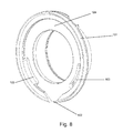
- FIG. 8 is an isometric view of the sliding sleeve (101) of the pressed release bearing FIG. 6 shown. It can be clearly seen that the sliding sleeve (101) next to the central opening only has a radial opening (102) and two axial openings (103), which serve over a circumferential gap (124) for the removal of dirt, moisture or for heat dissipation , It can be clearly seen that the radial openings (102) of the sliding sleeve (101) taper outwards.
- FIGS. 9a and 9b the first and the second sealing element (118, 122) are shown in detail.
- the first sealing element 118 has a stiffener with a metallic core disk 128 and a thickened root 126, which comprises three sealing lips 119a, 119b, 119c.
- the three sealing lips have an X-shape, and different sizes.
- the third sealing lip (119c) is slightly larger in diameter than the first and second sealing lips (119a, 119b).
- the biasing force between the second sealing lip (119b) and the corresponding sealing surface (S3) is realized by a taper of the lip wall thickness (127), as indicated by the arrows.
- the second sealing element (122) has a stiffener with a metallic core disc (128), and a thickened root (126), which comprises two sealing lips (119d, 119e).
- the two sealing lips (119d, 119e) have a V-shape and different sizes.
- the second sealing lip (119e) is slightly larger in diameter than the first sealing lip (119d).
- FIG. 10 an enlarged view of the first sealing element (118) and the capillary gap (123) is shown.
- the first sealing element (118) has a thickened root, which comprises three sealing lips of different sizes.
- the third sealing lip is slightly larger in diameter than the first and the second sealing lip and therefore has more rigidity. Due to the rigid design of this third, larger sealing lip and the root, a radial gap (a) is formed between the third sealing lip and the sealing surface (S3), against which the second sealing lip seals.
- the radial gap (a) remains unaffected both during assembly of the third, larger sealing lip, as well as by the abrasion of the first and / or second sealing lip and has the function of a labyrinth seal.
- the first and the second sealing lip are slightly smaller in diameter than the third, larger sealing lip and act with a certain clamping force radially against a sealing surface of the inner bearing ring.
- the first sealing lip of the sealing surface (S2) on the inner bearing ring is radially opposite, whereas the second sealing lip in their Radial direction is constantly in contact with the centrifugal disc and a contact seal on or with the sealing surface (S3) is formed.
- the first and the second sealing lip can also be provided without contact with a radial gap (a), so that they fulfill the function of a labyrinth seal.
- FIG. 11 shows an enlarged view of the second sealing element (122).
- the second sealing element (122) also has a thickened root (126) which preferably comprises two sealing lips (119d, 119e).
- the two sealing lips (119d, 119e) have different sizes, wherein the second sealing lip (119e) is slightly larger in diameter than the first sealing lip (119d) and therefore has more rigidity.
- Due to the rigid design a radial gap (a) is formed between the second sealing lip (119e) and the sealing surface (S1), against which the first sealing lip (119d) seals.
- the radial gap (a) remains unaffected during the assembly of the second sealing lip (119e) as well as by the abrasion of the first sealing lip (119d).
- the first sealing lip (119d) acts with a certain clamping force radially against the sealing surface (S1) of the inner bearing ring, so that it forms a contact seal on or with the sealing surface (S1).
- the biasing force between the first sealing lip (119d) and the sealing surface (S1) is realized by a defined lip wall thickness (127), a lever arm (L) and a defined angle ( ⁇ ), as indicated by the arrows.
- annular groove (129) is formed as a receiving area for a blocking means (121). This groove (129) is especially important as the space between the two sealing lips (119d, 119e) due to the angle ( ⁇ ) and the short lip seal is not sufficient for a functioning locking means.
Landscapes
- Engineering & Computer Science (AREA)
- General Engineering & Computer Science (AREA)
- Mechanical Engineering (AREA)
- Rolling Contact Bearings (AREA)
- Sealing Of Bearings (AREA)
- Mechanical Operated Clutches (AREA)
Abstract
Ausrückvorrichtung (100) für eine Reibungskupplung eines Kraftfahrzeuges, umfassend ein Führungsrohr (107), eine Schiebehülse (101), welche auf dem Führungsrohr axial verschiebbar ist und wenigstens eine radiale und axiale Öffnung (102, 103) umfasst, einen Halteabschnitt (104), an welchem ein Halteblech (105) befestigt ist, welches ein selbstjustierendes Ausrücklager (110) an einen Flansch der Schiebehülse drückt und wenigstens eine radiale Öffnung (108) umfasst, das Ausrücklager, welches einen drehfest zu der Schiebehülse angeordneten äußeren Lagerring (111), zwischen dem äußeren und einem inneren Lagerring angeordnete Wälzkörper (112) und einen umlaufenden inneren Lagerring (113) umfasst, wobei der innere Lagerring mit einem Betätigungselement der Reibungskupplung in Wirkverbindung steht, eine Schleuderscheibe (115), welche mit dem inneren Lagerring verbunden ist und ein erstes und zweites Dichtelement 118, 122), welche mit dem äußeren Lagerring verbunden sind.Release device (100) for a friction clutch of a motor vehicle, comprising a guide tube (107), a sliding sleeve (101) which is axially displaceable on the guide tube and comprises at least one radial and axial opening (102, 103), a holding section (104), on which a retaining plate (105) is fixed, which presses a self-aligning release bearing (110) on a flange of the sliding sleeve and at least one radial opening (108), the release bearing, which rotatably to the sliding sleeve arranged outer bearing ring (111) between the outer and an inner bearing ring arranged rolling elements (112) and a circumferential inner bearing ring (113), wherein the inner bearing ring is operatively connected to an actuating element of the friction clutch, a centrifugal disc (115) which is connected to the inner bearing ring and a first and second sealing element 118, 122) which are connected to the outer bearing ring.
Description
Die Erfindung betrifft eine Ausrückvorrichtung für eine Reibungskupplung eines Kraftfahrzeuges, umfassend ein Führungsrohr, eine Schiebehülse, welche auf dem Führungsrohr axial verschiebbar ist und wenigstens eine radiale und axiale Öffnung umfasst, einen Halteabschnitt, an welchem ein Halteblech befestigt ist, welches ein selbstjustierendes Ausrücklager an einen Flansch der Schiebehülse drückt und wenigstens eine radiale Öffnung umfasst, das Ausrücklager, welches einen drehfest zu der Schiebehülse angeordneten äußeren Lagerring, zwischen dem äußeren und einem inneren Lagerring angeordnete Wälzkörper und einen umlaufenden inneren Lagerring umfasst, wobei der innere Lagerring mit einem Betätigungselement der Reibungskupplung in Wirkverbindung steht, eine Schleuderscheibe, welche mit dem inneren Lagerring verbunden ist und ein erstes und zweites Dichtelement, welche mit dem äußeren Lagerring verbunden sind.The invention relates to a release device for a friction clutch of a motor vehicle, comprising a guide tube, a sliding sleeve, which is axially displaceable on the guide tube and at least one radial and axial opening comprises a holding portion to which a retaining plate is attached, which a self-aligning release bearing to a Presses the flange of the sliding sleeve and at least one radial opening, the release bearing, which rotatably to the sliding sleeve arranged outer bearing ring, between the outer and an inner bearing ring arranged rolling elements and a circumferential inner bearing ring, wherein the inner bearing ring with an actuating element of the friction clutch in An operative connection is, a slinger, which is connected to the inner bearing ring and a first and second sealing element, which are connected to the outer bearing ring.
Eine Reibungskupplung wird hauptsächlich in Kraftfahrzeuge eingebaut, um den Kraftfluss zwischen einem Motor und einem Getriebe beim Anfahren bzw. Gangwechsel zu trennen und zu schließen. Sie kann mechanisch, hydraulisch oder elektrisch betätigt werden und besteht aus einer Kupplungsscheibe, die von einer oder mehreren Federn mit einer Druckplatte an die Schwungscheibe des Motors gepresst wird. Beim Betätigen der Kupplung wird der Federdruck vom Ausrückhebel überwunden, so dass die Scheibe frei drehen kann und die Kupplung getrennt ist.A friction clutch is mainly installed in motor vehicles to separate and close the power flow between an engine and a transmission when starting or changing gears. It can be operated mechanically, hydraulically or electrically and consists of a clutch disc, which is pressed by one or more springs with a pressure plate to the flywheel of the engine. Upon actuation of the clutch, the spring pressure is overcome by the release lever, so that the disc can rotate freely and the clutch is disconnected.
Die Reibungskupplung ist im Betrieb schaltbar und nutzt den Reibungswiderstand zwischen zwei Platten, um Kräfte von einer Platte auf eine andere zu übertragen. Daher leistet die Kupplung eine große Reibarbeit, was zu einem starken mechanischen Abrieb der Kupplung führt, welcher durch die Betriebsbedingungen bestimmt ist und deshalb nur unwesentlich beeinflusst werden kann. Dazu kommt die thermische Belastung der Kupplung.The friction clutch is switchable during operation and uses the frictional resistance between two plates to transfer forces from one plate to another. Therefore, the clutch performs a large friction work, resulting in a strong mechanical abrasion of the clutch, which is determined by the operating conditions and therefore can be influenced only insignificantly. Added to this is the thermal load on the coupling.
Ausrückvorrichtungen zur Betätigung einer Reibungskupplung eines Kraftfahrzeuges umfassen als einen hauptsächlichen Bestandteil ein als Wälzlager ausgeführtes Ausrücklager. Das Ausrücklager wird im Antriebsstrang von Kraftfahrzeugen eingesetzt. Um eine möglichst lange Lebensdauer dieses Ausrücklagers zu gewährleisten, ist eine sorgfältige Abdichtung des Lagerinnenraums erforderlich. In dem Lagerinnenraum stehen die Wälzkörper mit den Laufbahnen des Lagers im kraftübertragenden Wälzkontakt. Typischerweise sind dafür unmittelbar am Wälzlager bzw. an zu dem Lager benachbarten Bauteilen berührende und/oder berührungsfreie Dichtungsanordnungen vorgesehen. Derartige Dichtungsanordnungen sind meist Elastomer- und/oder Labyrinthdichtungen, welche zusätzlich mit einem Sperrmittel gefüllte Aufnahmebereiche umfassen können. Die Hauptfunktion der Dichtungsanordnung ist einerseits die Vermeidung ein Schmierstoffaustritts und andererseits die Reduzierung eines Schmutz- bzw. Feuchtigkeitseintritts in den Lagerinnenraum. Bei berührenden Dichtungen ist jedoch ein Verschleiß unvermeidlich.Release devices for actuating a friction clutch of a motor vehicle comprise as a main component a release bearing designed as a roller bearing. The release bearing is used in the drive train of motor vehicles. To ensure the longest possible service life of this release bearing, a careful sealing of the bearing interior is required. In the bearing interior, the rolling elements are in contact with the raceways of the bearing in force-transmitting rolling contact. Typically, contacting and / or contact-free sealing arrangements are provided directly on the roller bearing or on components adjacent to the bearing. Such sealing arrangements are usually elastomer and / or labyrinth seals, which may additionally comprise receiving areas filled with a blocking agent. The main function of the seal assembly is on the one hand the avoidance of lubricant leakage and on the other hand the reduction of dirt or moisture ingress into the bearing interior. In contact seals, however, wear is inevitable.
Zusätzlich zu dem Staub aus mechanischem Abrieb sind die Lager der Kupplung durch Feuchtigkeit, Schwebstoffe und andere Schmutzpartikel aus der Umgebungsluft belastet. Dies ist besonders bei Wälzlagerdichtungen in Kraftfahrzeugen gegeben, welche außerordentlich großen Staub- und Schmutzmengen ausgesetzt sind, wie dies u. a. im Straßen- und Bergbau, sowie der Land- und Forstwirtschaft der Fall ist.In addition to the dust from mechanical abrasion, the bearings of the coupling are contaminated by moisture, suspended solids and other dirt particles from the ambient air. This is especially true for rolling bearing seals in motor vehicles, which are exposed to extremely large amounts of dust and dirt, such as This is the case in road and mining, as well as in agriculture and forestry.
Die in der Umgebungsluft enthaltenen Stäube und Schwebestoffe gelangen leicht in die Getriebeglocke und werden dort mit der zirkulierenden Luft unmittelbar an die Kuppelungsausrückvorrichtung transportiert. Dort lagern sich diese gemeinsam mit dem ohnehin vorhandenen Kupplungsabrieb ab, bevorzugt an den Dichtelementen des Ausrücklagers. Aufgrund der schwellenden Axialbelastung eines Ausrücklagers und der verschleißfördernden Aggressivität der Stäube und Schwebestoffe kommt es zu einer fortwährenden Verminderung der Wirksamkeit der Dichtsysteme des Lagers. Dies führt dazu, dass diese alsbald nicht mehr funktionieren, was schlussendlich zum Ausfall des Ausrücklagers und damit der gesamten Reibungskupplung führen kann.The dusts and suspended matter contained in the ambient air easily enter the bell housing and are transported there with the circulating air directly to the coupling release device. There they are stored together with the already present clutch wear, preferably on the sealing elements of the release bearing. Due to the swelling axial load of a release bearing and the wear-promoting aggressiveness of the dusts and suspended matter, there is a continuous reduction in the effectiveness of the sealing systems of the camp. This means that they soon no longer work, which can ultimately lead to failure of the release bearing and thus the entire friction clutch.
Gattungsgemäße Wälzlager für eine Ausrückvorrichtung zum Betätigen einer Reibungskupplung eines Kraftfahrzeuges sind in der
Problematisch bei den vorgeschlagenen Ausrückvorrichtungen ist jedoch, dass das Sperrmittel bei einer radialen Selbstjustierung des Ausrücklagers schrittweise aus dem Aufnahmebereich herausgedrückt werden kann. Zudem kann sich die Sperrmittelschicht auch von einem der Bauteile lösen, wodurch der Eintritt von Stäuben und Schwebestoffen ermöglicht wird.The problem with the proposed release devices, however, is that the blocking means can be pushed out step by step in a radial self-adjustment of the release bearing from the receiving area. In addition, the barrier layer can also dissolve from one of the components, which allows the entry of dusts and suspended matter.
Das Sperrmittel kann zudem direkt von den Stäuben und Schwebstoffen, welche sich in und an dem Ausrücklager sammeln, angegriffen werden. Dadurch wird die Sperrmittel-Eigenschaft negativ beeinflusst, so dass das Sperrmittel allmählich zum hauptsächlichen Störfaktor für die Hauptdichtung wird.In addition, the blocking agent can be attacked directly by the dusts and suspended particles that collect in and on the release bearing become. This negatively affects the blocking agent property, so that the blocking agent gradually becomes the main disturbance factor for the main seal.
Vor dem Hintergrund, eine Ausrückvorrichtung für eine Kraftfahrzeugreibungskupplung mit einem selbstjustierenden Ausrücklager bereitzustellen, welches auch unter extremen äußeren Bedingungen zuverlässig geschützt ist und eine hohe Lebensdauer erzielt, schlägt die
Allerdings kommt es auch bei der hier vorgeschlagenen Lösung dazu, dass das Sperrmittel direkt von den groben Stäuben und Schwebstoffen angegriffen wird, so dass die Sperrmittel-Eigenschaft negativ beeinflusst wird. Weiterhin wird das Sperrmittel aufgrund der undefinierten Form des Aufnahmebereichs und dem Fliehkraft-Effekt entlang der Deckelementinnenseite radial nach außen wandern, so dass sich die Menge an Sperrmittel kontinuierlich verringert. Dies ermöglicht allmählich der Eintritt von Fremdpartikeln in das Ausrücklager. Auf diese Weise wird daher lediglich Zeit bis zum verschleißbedingten Ausfall des Ausrücklagers gewonnen.However, it also comes with the proposed solution here that the blocking agent is attacked directly by the coarse dusts and suspended matter, so that the blocking agent property is adversely affected. Furthermore, due to the undefined shape of the receiving area and the centrifugal force effect, the blocking means will move radially outwards along the inner side of the cover element, so that the amount of blocking means is reduced continuously. This gradually allows the entry of foreign particles into the release bearing. In this way, therefore, only time is gained until the wear-related failure of the release bearing.
Da es für die Lebensdauer von Wälzlagern von entscheidender Bedeutung ist, deren Lagerinnenraum von äußeren Umwelteinflüssen zu schützen, wird auf aktuellem Stand der Technik zudem versucht, Dichtungen bzw. die Möglichkeit der Bildung von Aufnahmen für Sperrmittel zu optimieren. Dies kann unter anderem durch eine berührungsfreie Labyrinthdichtung geschehen, wie in der
Allerdings ergibt sich damit das Problem, dass die Fangrinne bei fortdauernder Einwirkung von Schmutz und Feuchtigkeit, besonders in extrem schwebstoff- und staubbelasteten Gebieten, verstopfen kann. Bei einer verstopften Fangrinne ist der Schmutzaustrieb derart vermindert wird, dass Schmutz ins Ausrücklager gelangen kann, was zu ausfallbedingten Wartungs- und Reparaturarbeiten des Lagers führt.However, this raises the problem that the gutter can clog when exposed to the effects of dirt and moisture, especially in extremely polluted and dusty areas. In a clogged gutter the dirt outlet is reduced so that dirt can get into the release bearing, resulting in failure maintenance and repair of the bearing.
Auf aktuellem Stand der Technik wird des Weiteren versucht, die Lebensdauer von Ausrücklagern dadurch zu verlängern, dass gezielt Ablagerungsbereiche für Fremdstoffe vorgesehen werden, welche in einem Zirkulationsbereich der Fremdstoffe angeordnet sind. Diesbezüglich ist auf die Offenlegungsschrift
Hierbei ergibt sich allerdings das Problem, dass die mit Haftmittel versehenen Bereiche insbesondere in extrem staub- und schmutzbelasteten Gebieten schnell voll sind oder die Kanäle aufgrund der Deponierung der wegzuleitenden Fremdstoffe verstopfen. Dann können die Fremdstoffe wieder ins Ausrücklager gelangen, was zu ausfallbedingten Wartungs- und Reparaturarbeiten führtHere, however, there is the problem that the areas provided with adhesive areas are quickly full especially in extremely dusty and polluted areas or clog the channels due to the landfill of the foreign matter to be removed. Then the foreign substances can get back into the release bearing, which leads to failure-related maintenance and repair work
Es besteht daher ein großer Bedarf an einer Ausrückvorrichtung für eine Reibungskupplung eines Kraftfahrzeuges mit einem selbstjustierendem Ausrücklager, welches zuverlässig und lang anhaltend gegen Verschmutzungen, wie Schwebestoffe, Stäube und Feuchtigkeitseintritt, geschützt ist. Es ist daher von großer Bedeutung ein Ausrücklager so gut abzudichten, dass die Schmutzpartikelmenge lokal, d.h. im Bereich des Lagerinneren, maximal reduziert wird und dass die Abdichtung einem möglichst geringen eigenen Verschleiß unterworfen ist. Ausgehend von diesem Punkt hat sich die Erfindung daher die Aufgabe gestellt, Wälzlager bereitzustellen, dessen Dichtelemente auch unter extremen äußeren und verschleißfördernden Bedingungen längere Lebenszeiten des Ausrücklagers und damit geringere Ausfallzeiten und Reparatur- bzw. Wartungskosten sicherstellen.There is therefore a great need for a release device for a friction clutch of a motor vehicle with a self-aligning release bearing, which is reliable and long-lasting protection against contamination, such as suspended matter, dusts and moisture ingress. It is therefore of great importance to seal a release bearing so well that the amount of contaminant is local, i. in the area of the bearing interior, maximum is reduced and that the seal is subject to the lowest possible own wear. Based on this point, the invention therefore has the task of providing bearings whose sealing elements ensure longer life of the release bearing and thus lower downtime and repair or maintenance costs even under extreme external and wear-promoting conditions.
Ein weiterer Aspekt, um die Lebensdauer des Ausrücklagers zu verlängern, ist, die im Lager entstehende Hitze nach außen abzutransportieren, da die nicht abgeführte Wärme die Lebensdauer des Lagers negativ beeinflusst. Bei den auf aktuellem Stand der Technik bekannten Vorschlägen für Dichtanordnungen bzw. Dichtsysteme in Ausrücklagern wird dieses Problem nicht thematisiert. Diese werden hingegen beispielsweise durch eine Schiebehülse stark abgekapselt, was zu einer Verminderung der Wärmeabfuhr führt. Daher hat sich die Erfindung des Weiteren die Aufgabe gestellt, das Wälzlager gezielt zu kühlen und die überschüssige Wärme in die Umgebung abzuleiten.Another aspect of extending the life of the release bearing is to remove the heat generated in the bearing to the outside, since the heat dissipated negatively affects the life of the bearing. In the known prior art proposals for sealing arrangements or sealing systems in release bearings this problem is not addressed. These are, however, strongly encapsulated, for example by a sliding sleeve, which leads to a reduction of heat dissipation. Therefore, it has become the invention further set the task to cool the rolling bearing targeted and dissipate the excess heat in the environment.
Aufgabe der Erfindung ist es also, eine Ausrückvorrichtung für eine Reibungskupplung eines Kraftfahrzeuges bereitzustellen, dessen ausfallbedingte Reparatur- und Wartungszeiten auf ein Minimum reduziert werden, indem das Ausrücklager zuverlässig und langlebig gegen in das Lagerinnere eindringende Verschmutzungen und austretende Schmierstoffen geschützt wird. Zudem wird die am Ausrücklager entstehende Wärme zuverlässig abgeleitet, was die Lebenszeit des Lagers zusätzlich erhöht.The object of the invention is therefore to provide a release device for a friction clutch of a motor vehicle whose failure-related repair and maintenance times are reduced to a minimum by the release bearing is reliably and durable protected against penetrating into the bearing interior contaminants and leaking lubricants. In addition, the heat generated at the release bearing is reliably dissipated, which additionally increases the lifetime of the bearing.
Diese Aufgabe wird durch die Ausrückvorrichtung für eine Reibungskupplung eines Kraftfahrzeuges mit den Merkmalen des unabhängigen Anspruchs gelöst, insbesondere indem die Schleuderscheibe mit dem Flansch der Schiebehülse einen umlaufenden Spalt ausbildet, die Schleuderscheibe eine konzentrische Strömung innerhalb der Ausrückvorrichtung erzeugt und das erste Dichtelement mit dem inneren Lagerring und der Schleuderscheibe eine Dichtstruktur ausbildet. Vorteilhafte Weiterbildungen der Erfindung, welche einzeln oder in Kombination realisierbar sind, sind in den Unteransprüchen dargestellt.This object is achieved by the disengaging device for a friction clutch of a motor vehicle with the features of the independent claim, in particular by the centrifugal disc with the flange of the sliding sleeve forms a circumferential gap, the centrifugal disc generates a concentric flow within the clutch and the first sealing element with the inner bearing ring and the centrifugal disc forms a sealing structure. Advantageous developments of the invention, which can be implemented individually or in combination, are shown in the subclaims.
Es wird eine Ausrückvorrichtung für eine Reibungskupplung eines Kraftfahrzeuges vorgeschlagen, welche ein Führungsrohr, eine auf dem Führungsrohr axial verschiebbaren Schiebehülse, einen Halteabschnitt, an welchem ein Halteblech befestigt ist, ein selbstjustierendes Ausrücklager, eine Schleuderscheibe und ein erstes und zweites Dichtelement umfasst. Die Ausrückvorrichtung kann in gezogener oder gedrückter Bauweise gebaut werden.It is proposed a disengaging device for a friction clutch of a motor vehicle, which is a guide tube, an axially displaceable on the guide tube sliding sleeve, a holding portion to which a retaining plate is attached, a self-aligning release bearing, a centrifugal disc and a first and second sealing element comprises. The release device can be built in pulled or pressed construction.
Unter dem Begriff "Schiebehülse" versteht sich eine auf dem Führungsrohr axial verschiebbare Hülse. Die Schiebehülse ist aus einem beliebigen Material herstellbar, dies ist jedoch im Rahmen der Erfindung nicht wesentlich. Diese ist zusätzlich zu ihrer zentrischen Öffnung mit weiteren Öffnungen versehen, wobei diese Öffnungen funktionale Öffnungen für die Erhöhung der Luftzirkulation und/oder den Abtransport von Verschmutzungen bzw. Wärme sind. Diese sind am Außenrand der Schiebehülse angeordnet.The term "sliding sleeve" is understood to be an axially displaceable sleeve on the guide tube. The sliding sleeve is made of any material, but this is not essential in the invention. This is in addition to its central opening provided with further openings, which openings are functional openings for increasing the air circulation and / or the removal of dirt or heat. These are arranged on the outer edge of the sliding sleeve.
Die Öffnungen sind radial und axial ausgerichtet. Bevorzugt umfasst die Schiebehülse wenigstens eine radiale und axiale Öffnung. Bevorzugt sind die radiale und axiale Öffnung in Höhe des Ausrücklagers angeordnet. Bevorzugt umfasst die Schiebehülse für ein gezogenes Ausrücklager wenigstens zwei radiale Öffnungen und eine axiale Öffnung. Für ein gedrücktes Ausrücklager umfasst die Schiebehülse bevorzugt eine radiale Öffnung und wenigstens zwei axiale Öffnungen.The openings are radially and axially aligned. Preferably, the sliding sleeve comprises at least one radial and axial opening. Preferably, the radial and axial openings are arranged at the level of the release bearing. Preferably, the sliding sleeve for a pulled release bearing comprises at least two radial openings and an axial opening. For a depressed release bearing, the sliding sleeve preferably comprises a radial opening and at least two axial openings.
Die radialen Öffnungen sind bevorzugt derart ausgestaltet, dass sich diese nach außen verjüngen, um so sicherzustellen, dass Schmutz aufgrund seines eigenen Gewichtes und/oder Wärme nach außen aus dem Ausrücklager geleitet werden. Gleichzeitig wird aufgrund der besonderen Ausgestaltung der Öffnungen und der Zentrifugalkraftströmung der Schleuderscheibe damit auch der Schmutzeintrag in das Ausrücklager verringert.The radial openings are preferably configured to taper outwardly so as to ensure that debris is conducted outwardly of the release bearing due to its own weight and / or heat. At the same time due to the special design of the openings and the centrifugal force flow of the centrifugal disc thus the dirt entry is reduced in the release bearing.
Natürlich können derartige radiale Öffnungen auch an anderen Stellen der Ausrückvorrichtung angebracht sein.Of course, such radial openings can also be attached to other locations of the release device.
Die axiale Öffnung ist so ausgestaltet, dass sich diese nach außen verjüngt. Somit wird hauptsächlich Wärme über eine nach außen enger werdende, trichterförmige Öffnung aus dem Ausrücklager ausgeleitet. Natürlich kann nicht verhindert werden, dass auch Schmutz über die axiale Öffnung aus dem Ausrücklager nach außen abtransportiert wird. Die abgeleitete Menge an Schmutz ist allerdings zu vernachlässigen, da dieser aufgrund seines eigenen Gewichtes und über die Zentrifugalkraft bevorzugt über die radialen Öffnungen ausgeleitet wird.The axial opening is designed so that it tapers to the outside. Thus, heat is mainly discharged through an outwardly narrowing, funnel-shaped opening from the release bearing. Of course, it can not be prevented that dirt is transported away via the axial opening from the release bearing to the outside. However, the deduced amount of dirt is negligible, as this is preferably discharged through the radial openings due to its own weight and the centrifugal force.
Die besondere Ausgestaltung der axialen Öffnung der Schiebehülse in Trichterform und die Zentrifugalkraftströmung bieten zudem den Vorteil, dass nur sehr wenig Schmutz von außen nach innen gelangen kann.The special design of the axial opening of the sliding sleeve in funnel shape and the centrifugal force flow also offer the advantage that only very little dirt can get from the outside inwards.
Die Schiebehülse kann zudem eine eingebrachte Nut aufweisen, welche die Montage des Halteblechs erleichtert und sicherstellt, dass in das Lager einfallender Schmutz gleich wieder aus dem Lager austransportiert wird.The sliding sleeve can also have an introduced groove, which facilitates the mounting of the retaining plate and ensures that any dirt entering the bearing is immediately removed from the bearing.
Der Begriff "Halteabschnitt" betrifft einen Abschnitt, an welchem ein Halteblech befestigt ist, welches ein selbstjustierendes Ausrücklager an einen Flansch der Schiebehülse drückt. Zwischen diesem Flansch und dem äußeren Lagerring des Ausrücklagers befindet sich ein Federelement. Bevorzugt ist der Flansch ein Radialflansch.The term "holding portion" refers to a portion to which a retaining plate is attached, which presses a self-aligning release bearing on a flange of the sliding sleeve. Between this flange and the outer bearing ring of the release bearing is a spring element. Preferably, the flange is a radial flange.
Das Halteblech ist an der Außenumfangsfläche des Haltebereichs verrollt und erstreckt sich unter Einfluss eines radialen Justierspaltes axial über das Ausrücklager. Das Halteblech greift an der von dem Haltebereich abgewandten Stirnseite des radial äußeren, drehfesten Lagerrings an das Ausrücklager an.The holding plate is rolled on the outer peripheral surface of the holding portion and extends under the influence of a radial adjusting gap axially over the release bearing. The holding plate engages on the end face remote from the holding area of the radially outer, non-rotatable bearing ring to the release bearing.
Bevorzugt umfasst das Halteblech wenigstens eine radiale Öffnung, welche am Außenrand des Halteblechs angeordnet ist. Über diese radiale Öffnung wird mittels der von der Schleuderscheibe erzeugten Zentrifugalkraft Schmutz und/oder Wärme nach außen aus dem Ausrücklager geleitet. Der Schmutz wird zudem aufgrund seines eigenen Gewichtes nach außen geleitet. Somit wird erreicht, dass der Schmutzeintrag in das Ausrücklager deutlich verringert bzw. vermieden wird.Preferably, the retaining plate comprises at least one radial opening, which is arranged on the outer edge of the retaining plate. About this radial opening dirt and / or heat is conducted to the outside from the release bearing by means of the centrifugal force generated by the centrifugal disc. The dirt is also directed to the outside due to its own weight. This ensures that the entry of dirt into the release bearing is significantly reduced or avoided.
Es versteht sich, dass wenigstens eine weitere derartige radiale Öffnung auch an einer anderen Stelle der Ausrückvorrichtung angebracht sein kann.It is understood that at least one further such radial opening can also be attached to another location of the release device.
Unter dem Begriff "Ausrücklager" versteht sich ein Ausrück- oder Wälzlager, welches einen drehfest zu einer Schiebehülse angeordneten äußeren Lagerring, zwischen dem äußeren und einem inneren Lagerring angeordnete Wälzkörper und einen umlaufenden inneren Lagerring umfasst. Der innere Lagerring ist mittels eines Axialfortsatzes über das Ausrücklager hinaus verlängerbar und steht mit einem Betätigungselement der Reibungskupplung in Wirkverbindung. Bevorzugt ist das Ausrücklager selbstjustierend ausgestaltet, d.h. es zentriert sich selbst in radialer Ausrichtung auf der Kurbelwelle. Der Fachmann weis dies zu realisieren.The term "release bearing" is understood to mean a disengaging or roller bearing, which comprises an outer bearing ring, arranged rotatably relative to a sliding sleeve, between the outer and an inner bearing ring arranged rolling elements and a circumferential inner bearing ring. The inner bearing ring can be extended beyond the release bearing by means of an axial extension and is in operative connection with an actuating element of the friction clutch. Preferably, the release bearing is configured self-adjusting, i. it centers itself in radial alignment on the crankshaft. The expert knows to realize this.
Der Begriff "Schleuderscheibe" betrifft eine fest verbaute, kreisringförmige Scheibe, welche mit dem inneren Lagerring verbunden ist. Bevorzugt ist die Schleuderscheibe an der von der Wälzkörperlaufbahn abgewandten Umfangsfläche des drehenden inneren Lagerrings fixiert und umschließt eine von dessen Stirnseiten. Die Schleuderscheibe ist derart ausgebildet, dass diese mit dem Flansch der Schiebehülse einen umlaufenden Spalt bildet, durch welchem Verschmutzungen und Wärme abgeleitet werden.The term "slinger" refers to a permanently installed, annular disc which is connected to the inner bearing ring. Preferably, the centrifugal disc is fixed to the side facing away from the rolling body circumferential surface of the rotating inner bearing ring and encloses one of its end faces. The centrifugal disc is designed such that it with the flange of the Sliding sleeve forms a circumferential gap through which dirt and heat are dissipated.
Die Schleuderschiebe kann aus einem beliebigen Material bestehen und verschiedene Formen aufweisen.The sling can be made of any material and have different shapes.
Die Schleuderscheibe erzeugt bevorzugt eine konzentrische Strömung innerhalb der Ausrückvorrichtung, welche durch die Zentrifugalkraft radial nach außen abgelenkt wird. Mit dieser Strömung wird somit Wärme und Schmutz abtransportiert bzw. mitgerissen. Bevorzugt führt die Strömung dazu, dass Verschmutzungen aus dem Ausrücklager über die radiale Öffnung der Schiebehülse und/oder die radiale Öffnung des Halteblechs nach außen abtransportiert bzw. mitgerissen werden. Zudem reißt die Strömung Wärme aus dem Ausrücklager über die radiale und/oder axiale Öffnung der Schiebehülse und/oder die radiale Öffnung des Halteblechs mit.The centrifugal disc preferably generates a concentric flow within the disengaging device, which is deflected radially outwards by the centrifugal force. With this flow thus heat and dirt is carried away or entrained. Preferably, the flow causes contaminants from the release bearing via the radial opening of the sliding sleeve and / or the radial opening of the retaining plate to be transported to the outside or entrained. In addition, the flow tears heat from the release bearing via the radial and / or axial opening of the sliding sleeve and / or the radial opening of the retaining plate.
Der Begriff "Dichtelement" betrifft ein Mittel zur Abdichtung des Ausrücklagers. Bevorzugt umfasst die Ausrückvorrichtung zwei Dichtelemente. Das erste Dichtelement dichtet den Wälzkörperraum zur der Innenseite des Ausrücklagers ab, wohingegen das zweite Dichtelement den Wälzkörperraum zur Außenseite des Ausrücklagers abdichtet. Beide Dichtelemente sind mit dem äußeren Lagerring verbunden und bilden bevorzugt eine Labyrinthdichtung aus. Bevorzugt sind die Dichtelemente vulkanisiert und fixiert.The term "sealing element" refers to a means for sealing the release bearing. Preferably, the release device comprises two sealing elements. The first sealing element seals the Wälzkörperraum to the inside of the release bearing, whereas the second sealing element seals the Wälzkörperraum to the outside of the release bearing. Both sealing elements are connected to the outer bearing ring and preferably form a labyrinth seal. Preferably, the sealing elements are vulcanized and fixed.
Bevorzugt bildet das erste Dichtelement mit dem inneren Lagerring auf der einen Seite und der Schleuderscheibe auf der anderen Seite eine Dichtstruktur aus, welche das Ausrücklager zuverlässig vor eindringenden Fremdpartikeln bzw. Feuchtigkeit schützt.The first sealing element with the inner bearing ring on one side and the centrifugal disk on the other side preferably form a sealing structure which reliably protects the release bearing against the penetration of foreign particles or moisture.
Der Schutz des Ausrücklagers basiert darauf, dass mittels der von der Schleuderscheibe erzeugten Zentrifugalkraftströmung und des eigenen Gewichtes der Fremdpartikel, Schwebstoffe und Stäube, diese über die radiale und/oder axiale Öffnung der Schiebehülse nach außen abtransportiert werden. Auf diese Weise wird bereits eine hohe Abschirmung des Ausrücklagers erreicht.The protection of the release bearing is based on the fact that by means of the centrifugal force flow generated by the centrifugal disc and the own weight of foreign particles, suspended solids and dusts, they are transported to the outside via the radial and / or axial opening of the sliding sleeve. In this way, a high shielding of the release bearing is already achieved.
Es kann jedoch der Fall auftreten, dass dennoch Schwebstoffe bzw. Stäube aufgrund der Bewegung des Lagerinneren über einen Kapillarspalt nach innen wandern. Der Kapillarspalt ist derart realisiert, dass sich dessen begrenzende Flächen, d.h. der umlaufende innere Lagerring und der feststehende äußere Lagerring, gerade nicht berühren und dieser von dem Justagevorgang des Ausrücklagers nicht beeinflusst wird. Der Kapillarspalt erweitert sich in axialer Richtung zu dem ersten Dichtelement, welches die Schwebstoffe bzw. Stäube aufhält und wenigstens eine Dichtlippe aufweist. Zudem schützt das erste Dichtelement das Ausrücklager vor ausdringenden Schmierstoffen. Bevorzugt sind wenigsten zwei Dichtlippen umfasst, noch mehr bevorzugt drei Dichtlippen.However, it may be the case that suspended particles or dusts still migrate inwards due to the movement of the bearing inside over a capillary gap. The capillary gap is realized in such a way that its bounding surfaces, i. the circumferential inner bearing ring and the fixed outer bearing ring, just do not touch and this is not affected by the adjustment process of the release bearing. The capillary gap widens in the axial direction to the first sealing element, which holds the suspended matter or dusts and has at least one sealing lip. In addition, the first sealing element protects the release bearing against escaping lubricants. Preferably, at least two sealing lips are included, more preferably three sealing lips.
Auf der Außenseite des Ausrücklagers ist die Belastung der Dichtung mit Schwebstoffen bzw. Stäuben im Vergleich zu der auf der Lagerinnenseite sehr gering, da diese problemlos nach außen abfallen können. D. h., dass die Lageraußenseite weniger anfällig für Verschmutzungen ist.On the outside of the release bearing the load of the seal with suspended matter or dusts is very low compared to that on the inside of the bearing, as they can easily fall outwards. That is, the bearing outside is less susceptible to contamination.
Falls dennoch Schwebstoffe bzw. Stäube versuchen sollten, in das Lager einzudringen bzw. Schmierstoffe versuchen sollten, aus diesem nach außen zu gelangen, werden diese dann von dem zweiten Dichtelement aufgehalten. Das zweite Dichtelement weist wenigstens eine Dichtlippe auf. Bevorzugt sind wenigsten zwei Dichtlippen umfasst, noch mehr bevorzugt drei Dichtlippen.If, nevertheless, suspended particles or dusts should attempt to penetrate the bearing or lubricants should try to escape from the latter, they are then stopped by the second sealing element. The second sealing element has at least one sealing lip. Preferably, at least two sealing lips are included, more preferably three sealing lips.
Beide Dichtelemente sind berührungsfreie Labyrinthdichtungen, welche mit nach außen gerichteten Dichtlippen ausgeführt sind. Diese sind derart konstruiert, dass nur ein sehr kleiner Spalt zwischen der Dichtung und dem inneren Lagerraum verbleibt, so dass diese nicht schleift und folglich auch nicht durch Reibung abgenutzt werden kann. Die sich zwischen den Dichtlippen befindenden Bereiche können zudem einen Aufnahmebereich für ein Sperrmittel ausbilden. Der Aufnahmebereich kann alternativ eine Schmiermittel-Reserve für das Lager enthalten.Both sealing elements are non-contact labyrinth seals, which are designed with outwardly directed sealing lips. These are designed so that only a very small gap between the seal and the inner storage space remains so that it does not drag and therefore can not be worn by friction. The areas located between the sealing lips can also form a receiving area for a blocking means. The receiving area may alternatively contain a lubricant reserve for the bearing.
Mittels der Dichtlippen und der mit Sperrmittel befüllten Aufnahmeräume wird eine zuverlässige Abdichtung des Ausrücklagers erreicht, so dass sich die Ausfallzeit für Reparatur- und/oder Wartungsarbeiten drastisch reduziert. Folglich sinken damit auch die Kosten, da weniger Ausfälle auftreten bzw. weniger Reparatur- und/oder Wartungsarbeiten notwendig sind.By means of the sealing lips and filled with blocking agent receiving spaces a reliable seal of the release bearing is achieved, so that the downtime for repair and / or maintenance drastically reduced. As a result, the costs are also reduced, since fewer failures occur or less repair and / or maintenance is necessary.
Alternativ können die Dichtelemente auch berührend ausgestaltet sein. Bevorzugt weisen die Dichtlippen dann eine erhöhte Abriebfestigkeit auf, um abriebbedingte Abnutzungen zu vermeiden. Bei der Berührungsdichtung liegen die Dichtkanten der Dichtlippen im Schleifkontakt am inneren Lagerring an und dichten somit das Ausrücklager gegen äußere Einflüsse ab. Vorteilhafterweise hindert das Dichtungskonzept mit mehreren berührenden Dichtlippen einen großen Teil der Feinstaubpartikel daran, in den Aufnahmebereich für das Sperrmittel zu gelangen.Alternatively, the sealing elements can also be designed to be touching. Preferably, the sealing lips then have an increased abrasion resistance, in order to avoid abrasion-related wear. In the contact seal, the sealing edges of the sealing lips in the sliding contact on the inner bearing ring and thus seal the release bearing against external influences. Advantageously, the sealing concept with a plurality of contacting sealing lips prevents a large part of the fine dust particles from reaching the receiving area for the blocking agent.
In einer bevorzugten Ausgestaltung weist das erste Dichtelement, welches ein inneres ringförmiges Dichtelement ist, eine Versteifung mit einer metallischen Kernscheibe, beispielsweise aus Stahl, wie rostfreien Edelstahl, und eine verdickte Wurzel auf, welche bevorzugt drei Dichtlippen umfasst. Die drei Dichtlippen weisen dabei eine bestimmte Lippengeometrie, insbesondere eine X-Form, auf. Im Vergleich zu den verschieden aus dem Stand der Technik bekannten Lösungen wird mittels der verdickten Wurzel eine stabile Form des Dichtelements erreicht. Vorteilhafterweise wird dadurch bei der Montage des ersten Dichtelements sichergestellt, dass es zu keiner Bewegung, wie einer Verschwenkbewegung, im Bereich der verdickten Wurzel kommt.In a preferred embodiment, the first sealing element, which is an inner annular sealing element, a stiffener with a metallic core disc, for example made of steel, such as stainless steel, and a thickened root, which is preferred includes three sealing lips. The three sealing lips have a certain lip geometry, in particular an X-shape. In comparison to the various known from the prior art solutions a stable shape of the sealing element is achieved by means of the thickened root. Advantageously, this ensures during assembly of the first sealing element that there is no movement, such as a pivoting movement, in the region of the thickened root.
Weiterhin bevorzugt weisen die Dichtlippen unterschiedliche Größen auf. Die verdickte Wurzel umfasst daher eine erste Dichtlippe, eine zweite Dichtlippe und eine dritte Dichtlippe, wobei die dritte Dichtlippe im Durchmesser etwas größer als die erste und die zweite Dichtlippe ist. Dies bietet den Vorteil, dass die dritte, größere Dichtlippe mehr Steifigkeit aufweist. Durch die steife Gestaltung dieser dritten, größeren Dichtlippe und der Wurzel bildet sich zwischen der dritten Dichtlippe im Vergleich zu den kleineren Dichtlippen, insbesondere zu der zweiten Dichtlippe, ein definierter Radialspalt. D.h. zwischen der dritten Dichtlippe und der Dichtfläche, gegen welche die zweite Dichtlippe abdichtet, bildet sich ein Radialspalt. Der Radialspalt bleibt sowohl bei der Montage der dritten, größeren Dichtlippe, als auch durch den Abrieb der ersten und/oder zweiten Dichtlippe unbeeinflussbar gleich. Daraus folgt, dass der Radialspalt, im Vergleich zu aus dem Stand der Technik bekannten Systemen, unabhängig von dem Abrieb der ersten und/oder zweite Dichtlippe ist. Der Radialspalt hat dabei die Funktion einer Labyrinthdichtung.Furthermore, the sealing lips preferably have different sizes. The thickened root therefore comprises a first sealing lip, a second sealing lip and a third sealing lip, wherein the third sealing lip is slightly larger in diameter than the first and the second sealing lip. This offers the advantage that the third, larger sealing lip has more rigidity. Due to the rigid design of this third, larger sealing lip and the root, a defined radial gap is formed between the third sealing lip in comparison to the smaller sealing lips, in particular to the second sealing lip. That between the third sealing lip and the sealing surface, against which seals the second sealing lip, a radial gap is formed. The radial gap remains unaffected both during assembly of the third, larger sealing lip, as well as by the abrasion of the first and / or second sealing lip. It follows that the radial gap, in comparison to systems known from the prior art, is independent of the abrasion of the first and / or second sealing lip. The radial gap has the function of a labyrinth seal.
Die erste und die zweite Dichtlippe sind im Durchmesser etwas kleiner als die dritte, größere Dichtlippe und wirken mit einer gewissen Spannkraft radial gegen wenigstens eine Dichtfläche des inneren Lagerrings. Dabei steht die erste Dichtlippe einer Dichtfläche am inneren Lagerring radial gegenüber, wohingegen die zweite Dichtlippe in ihrer radialen Richtung ständig mit der Schleuderscheibe in Kontakt steht und eine Berührungsdichtung an bzw. mit einer anderen Dichtfläche, als die der ersten Dichtlippe, ausbildet.The first and the second sealing lip are slightly smaller in diameter than the third, larger sealing lip and act with a certain clamping force radially against at least one sealing surface of the inner bearing ring. The first sealing lip of a sealing surface is on the inner Bearing ring radially opposite, whereas the second sealing lip in its radial direction is constantly in contact with the centrifugal disc and a contact seal on or with a different sealing surface, as that of the first sealing lip, is formed.
Im Rahmen der Erfindung ist es weiterhin bevorzugt, dass die Vorspannkraft zwischen der zweiten Dichtlippe und der entsprechenden Dichtfläche durch eine Verjüngung der Lippenwandstärke realisierbar ist. Zudem können die erste und die zweite Dichtlippe auch berührungslos mit einem Radialspalt versehen sein, so dass sie die Funktion einer Labyrinthdichtung erfüllen.In the context of the invention it is further preferred that the biasing force between the second sealing lip and the corresponding sealing surface is realized by a taper of the lip wall thickness. In addition, the first and the second sealing lip can also be provided without contact with a radial gap, so that they fulfill the function of a labyrinth seal.
In einer weiteren bevorzugten Ausgestaltung der Erfindung ist das zweite Dichtelement aus einem Elastomer. Zudem ist das zweite Dichtelement mit einer metallischen Kernscheibe, beispielsweise aus Stahl, wie rostfreien Edelstahl, versteift. Bei der Herstellung wird die Kernscheibe dabei mit dem Elastomer von außen angespritzt.In a further preferred embodiment of the invention, the second sealing element is made of an elastomer. In addition, the second sealing element is stiffened with a metallic core disk, for example made of steel, such as stainless steel. During production, the core disk is molded with the elastomer from the outside.
Das zweite Dichtelement ist dabei bevorzugt zwischen dem inneren Lagerring und dem äußeren Lagerring angeordnet, sowie am äußeren Lagerring verankert. Zudem weist das zweite Dichtelement eine verdickte Wurzel auf, welche bevorzugt zwei Dichtlippen umfasst. Die zwei Dichtlippen weisen dabei eine bestimmte Lippengeometrie, insbesondere eine V-Form, auf. Im Vergleich zu den verschieden aus dem Stand der Technik bekannten Lösungen wird mittels der verdickten Wurzel eine stabile Form des Dichtelements erreicht. Vorteilhafterweise wird dadurch bei der Montage des zweiten Dichtelements sichergestellt, dass es zu keiner Bewegung, wie einer Verschwenkbewegung, im Bereich der verdickten Wurzel kommt. Weiterhin bevorzugt weisen die zwei Dichtlippen unterschiedliche Größen auf. Die verdickte Wurzel umfasst daher eine erste Dichtlippe und eine zweite Dichtlippe, wobei die zweite Dichtlippe im Durchmesser etwas größer als die erste Dichtlippe ist. Dies bietet den Vorteil, dass die zweite, größere Dichtlippe mehr Steifigkeit aufweist. Durch die steife Gestaltung dieser zweiten, größeren Dichtlippe und der Wurzel lässt sich im Vergleich zu der ersten, kleineren Dichtlippe ein definierter Radialspalt bilden. D.h. zwischen der zweiten, größeren Dichtlippe und der Dichtfläche, gegen welche die erste Dichtlippe abdichtet, bildet sich ein Radialspalt. Der Radialspalt bleibt sowohl bei der Montage der zweiten, größeren Dichtlippe, als auch durch den Abrieb der ersten, kleineren Dichtlippe unbeeinflussbar gleichbleibend ist. Daraus folgt, dass der Radialspalt, im Vergleich zu aus dem Stand der Technik bekannten Systemen, unabhängig von dem Abrieb der ersten, kleineren Dichtlippe ist. Der Radialspalt hat dabei die Funktion einer Labyrinthdichtung und/oder einer Spaltdichtung.The second sealing element is preferably arranged between the inner bearing ring and the outer bearing ring, and anchored to the outer bearing ring. In addition, the second sealing element has a thickened root, which preferably comprises two sealing lips. The two sealing lips have a certain lip geometry, in particular a V-shape. In comparison to the various known from the prior art solutions a stable shape of the sealing element is achieved by means of the thickened root. Advantageously, this ensures during assembly of the second sealing element that there is no movement, such as a pivoting movement, in the region of the thickened root. Further preferably, the two sealing lips have different sizes. The thickened root therefore comprises a first sealing lip and a second sealing lip, wherein the second sealing lip is slightly larger in diameter than the first sealing lip. This offers the advantage that the second, larger sealing lip has more rigidity. Due to the rigid design of this second, larger sealing lip and the root, a defined radial gap can be formed in comparison to the first, smaller sealing lip. That is, between the second, larger sealing lip and the sealing surface, against which seals the first sealing lip, a radial gap is formed. The radial gap remains unaffected, both during assembly of the second, larger sealing lip, as well as by the abrasion of the first, smaller sealing lip is unchangeable. It follows that, compared to systems known from the prior art, the radial gap is independent of the abrasion of the first, smaller sealing lip. The radial gap has the function of a labyrinth seal and / or a gap seal.
Die erste, kleinere Dichtlippe wirkt mit einer gewissen Spannkraft radial gegen eine Dichtfläche des inneren Lagerrings. D.h., die erste, kleinere Dichtlippe steht in ihrer radialen Richtung ständig mit dem inneren Lagerring in Kontakt und bildet eine Berührungsdichtung an bzw. mit der Dichtfläche aus. Dabei steht diese erste, kleinere Dichtlippe der Dichtfläche im inneren Lagerring radial gegenüber.The first, smaller sealing lip acts with a certain clamping force radially against a sealing surface of the inner bearing ring. That is, the first, smaller sealing lip in its radial direction is constantly in contact with the inner bearing ring and forms a contact seal on or with the sealing surface. Here, this first, smaller sealing lip of the sealing surface in the inner bearing ring is radially opposite.
Zudem bevorzugt ist die Dichtfläche ein geschliffener Lagerring-Innenbord, welcher eine hohe Messgenauigkeit aufweist und der mit großer Oberflächengüte herstellbar ist. Daraus folgt, dass an bzw. mit der Dichtfläche eine besonders zuverlässige Abdichtung erreicht wird. Die Notwendigkeit einer derartigen besonders zuverlässigen Abdichtung zeigt sich beispielsweise bei der Verwendung der Dichtung bei Fahrzeugen, wie Baustellen- oder landwirtschaftlichen Fahrzeugen, die aufgrund ihres Einsatzgebietes einer hohen Feuchtigkeits- und/oder Staubbelastung ausgesetzt sind.In addition, preferably, the sealing surface is a ground bearing ring inboard, which has a high accuracy and which can be produced with high surface quality. It follows that on or with the sealing surface a particularly reliable seal is achieved. The need for such a particularly reliable seal can be seen for example in the use of the seal in vehicles, such as construction or agricultural vehicles, which are exposed due to their field of application of a high moisture and / or dust load.
Im Rahmen der Erfindung ist es daher weiterhin bevorzugt, dass die Vorspannkraft zwischen der ersten, kleineren Dichtlippe und der Dichtfläche durch eine definierte Lippenwandstärke, einen Hebelarm und/oder einen definierten Winkel realisierbar ist. Dies ist besonders vorteilhaft, da die Vorspannkraft der Dichtung nun nicht mehr allein durch eine Verschwenkbewegung an der Wurzel erzeugt wird.In the context of the invention, it is therefore further preferred that the biasing force between the first, smaller sealing lip and the sealing surface by a defined lip wall thickness, a lever arm and / or a defined angle can be realized. This is particularly advantageous because the biasing force of the seal is no longer generated solely by a pivoting movement at the root.
Des Weiteren ist es bevorzugt, dass sich zwischen der ersten und der zweiten Dichtlippe, insbesondere auf dem rotierenden inneren Lagerring, eine ringförmige Nut als Aufnahmebereich für ein Sperrmittel ausbildet. Es ist dabei als erfindungswesentlich erkannt worden, dass diese Nut als Aufnahmebereich für ein Sperrmittel dient. Dies ist besonders vorteilhaft, da der Platz zwischen den beiden Dichtlippen aufgrund des Winkels und der kurzen Lippendichtung nicht für ein funktionsfähiges Sperrmittel ausreicht. Durch eine Erweiterung des Raumes zwischen den beiden Dichtlippen mit einer Nut, wird dieses Problem zuverlässig gelöst. Im Rahmen der Erfindung kann die Nut hierbei verschiedene Formen annehmen.Furthermore, it is preferred that between the first and the second sealing lip, in particular on the rotating inner bearing ring, an annular groove forms as a receiving area for a locking means. It has been recognized as essential to the invention that this groove serves as a receiving area for a blocking agent. This is particularly advantageous because the space between the two sealing lips is not sufficient for a functioning locking means due to the angle and the short lip seal. By extending the space between the two sealing lips with a groove, this problem is reliably solved. In the context of the invention, the groove can assume different forms.
Aufgrund der vorgeschlagenen Ausbildung des zweiten Dichtelements wird vorteilhafterweise erreicht, dass die erste, berührende Dichtlippe bereits einen großen Anteil an Staubpartikeln blockiert. Die penetrierenden, feinstaubigen Partikel werden dabei durch den gebildeten Aufnahmebereich für das Sperrmittel abgefangen, indem das Sperrmittel in der Nut durch die von dem rotierenden inneren Lagerring erzeugte Fliehkraft eine Abschirmung aufbaut. Durch diese Abschirmung werden die Feinstaubpartikeln abgefangen, welche durch die Dichtung durchgegangen sind. Der Radialspalt zwischen der zweiten, größeren Dichtlippe und der Dichtfläche hat dabei die Funktion einer Labyrinthdichtung und/oder einer Spaltdichtung, so dass die restlichen penetrierenden feinstaubigen Partikel beim Eindringen in den Fettraum zuverlässig gehindert werden.Due to the proposed design of the second sealing element is advantageously achieved that the first, touching sealing lip already blocks a large proportion of dust particles. The penetrating, fine-dust particles are intercepted by the formed receiving area for the locking means by the blocking means in the groove by the centrifugal force generated by the rotating inner bearing ring builds up a shield. By this shielding the fine dust particles are intercepted, which have gone through the seal. The radial gap between The second, larger sealing lip and the sealing surface in this case has the function of a labyrinth seal and / or a gap seal, so that the remaining penetrating finely particulate particles are reliably prevented from penetrating into the fat space.
Dieses Dichtungskonzept kann sowohl bei gezogenen, als auch bei gedrückten Ausrücklagern eingesetzt werden. Zudem ist es möglich, dass dieses Konzept für die Abdichtung aller Lagerseiten, wie beispielsweise der Motorseite und/oder der Getriebeseite verwendet wird. Bei einem gedrückten Ausrücklager wird, aufgrund der Montage des inneren Lagerrings, die erste, berührende Dichtlippe gedreht. Bevorzugt erfolgt diese Drehung um 180°, so dass die erste, berührende Dichtlippe nach innen, d.h. in Richtung des Fettraumes, zeigt. Die zweite, größere Dichtlippe zeigt nach außen, d.h. in Richtung der Umgebung des Ausrücklagers, und weist einen Spalt zu der Dichtfläche auf.This sealing concept can be used with both pulled and pressed release bearings. In addition, it is possible that this concept is used for the sealing of all bearing sides, such as the engine side and / or the transmission side. When the release bearing is depressed, the first contacting sealing lip is rotated due to the assembly of the inner bearing ring. Preferably, this rotation is 180 °, so that the first, contacting sealing lip is inwardly, i. in the direction of the fat room, shows. The second, larger sealing lip faces outwards, i. in the direction of the environment of the release bearing, and has a gap to the sealing surface.
Der Begriff "Sperrmittel" betrifft ein Schmiermittel oder eine Zusammensetzung, wie ein Fett, eine Paste und/oder ein anderes geeignetes Schmiermittel, welches den Eintritt von Schmutz in das Ausrücklager blockiert und so äußere Fremdpartikel und Wasser primär von der Dichtungsanordnung und sekundär von dem Lagerinneren fernhält. Bevorzugt ist das Sperrmittel ein Schmiermittel, ein Fett und/oder eine Paste. Noch mehr bevorzugt ist das Sperrmittel temperaturbeständig.The term "barrier agent" refers to a lubricant or composition, such as a grease, paste and / or other suitable lubricant, which blocks the entry of debris into the release bearing and thus external foreign particles and water primarily from the seal assembly and secondarily from the bearing interior keeps. Preferably, the blocking agent is a lubricant, a grease and / or a paste. Even more preferably, the barrier means is temperature resistant.
Bevorzugt ist das Sperrmittel in einem Aufnahmebereich vorhanden und bildet ein Depot, welches bei Vorhandensein einer Dichtungsanordnung als eine zwischengelagerte Dichtung wirkt. Infolge wird die fremdartige Belastung an der Dichtungsanordnung und damit der dort auftretende Verschleiß reduziert, wodurch die Lebensdauer des Wälzlagers beachtlich gesteigert wird. Mittels des Sperrmittels wird somit erreicht, dass in der Umgebung des Ausrücklagers auftretende Fremdpartikel nicht so leicht in das Lagerinnere vordringen. Verständlicherweise bedeutet dies nicht, dass lediglich das Eindringen von Fremdpartikeln, wie Schmutz, Schwebstoffen und Stäuben verhindert wird, sondern natürlich auch das Eindringen von Feuchtigkeit und das Ausdringen von Schmierstoffen aus dem Lagerinneren.Preferably, the blocking means is present in a receiving area and forms a depot, which acts in the presence of a seal arrangement as an intermediate bearing seal. As a result, the foreign load on the seal assembly and thus the reduces wear occurring there, whereby the life of the bearing is considerably increased. By means of the blocking means is thus achieved that occur in the environment of the release bearing foreign particles not easily penetrate into the bearing interior. Understandably, this does not mean that only the penetration of foreign particles, such as dirt, suspended matter and dusts is prevented, but of course the ingress of moisture and the discharge of lubricants from the bearing interior.
Es wird davon ausgegangen, dass die Definitionen und Ausführungen der oben genannten Begriffe für alle in dieser Beschreibung im Folgenden beschriebenen Aspekte gelten, sofern nichts anders angegeben ist.It is understood that the definitions and embodiments of the above terms apply to all aspects described below in this specification, unless otherwise specified.
Weitere Einzelheiten, Merkmale und Vorteile der Erfindung ergeben sich aus der nachfolgenden Beschreibung des bevorzugten Ausführungsbeispiels in Verbindung mit den Unteransprüchen. Hierbei können die jeweiligen Merkmale für sich alleine oder zu mehreren in Kombination miteinander verwirklicht sein. Die Erfindung ist nicht auf die Ausführungsbeispiele beschränkt. Die Ausführungsbeispiele sind in den Figuren schematisch dargestellt. Gleiche Bezugsziffern in den einzelnen Figuren bezeichnen dabei gleiche oder funktionsgleiche bzw. hinsichtlich ihrer Funktion einander entsprechende Elemente.Further details, features and advantages of the invention will become apparent from the following description of the preferred embodiment in conjunction with the subclaims. In this case, the respective features can be implemented on their own or in combination with one another. The invention is not limited to the embodiments. The embodiments are shown schematically in the figures. The same reference numerals in the individual figures designate the same or functionally identical or with respect to their function corresponding elements.
Im Einzelnen zeigt:
Figur 1- eine Teilschnittdarstellung einer gezogenen Ausrückvorrichtung mit zwei Ausrücklagern;
Figur 2- eine vergrößerte Darstellung der Dichtungsanordnung des gezogenen Ausrücklagers aus
Figur 1 ; Figur 3- eine vergrößerte Teilschnittdarstellung des gezogenen Ausrücklagers aus
Figur 1 ; - Figur 4
- in isometrischer Darstellung eine Schiebehülse für das gezogene Ausrücklager;
- Figur 5
- eine Schiebehülse mit einem Halteblech in isometrischer Darstellung für das gezogene Ausrücklager;
- Figur 6
- eine Teilschnittdarstellung einer gedrückten Ausrückvorrichtung mit zwei Ausrücklagern;
- Figur 7
- eine vergrößerte Darstellung des gedrückten Ausrücklagers aus
Figur 6 ; - Figur 8
- in isometrischer Darstellung eine Schiebehülse für das gedrückte Ausrücklager;
- Figur 9
- eine detaillierte Darstellung des ersten und zweiten Dichtelements;
- Figur 10
- eine vergrößerte Darstellung des ersten Dichtungselements; und
- Figur 11
- eine vergrößerte Darstellung des zweiten Dichtungselements.
- FIG. 1
- a partial sectional view of a pulled release device with two release bearings;
- FIG. 2
- an enlarged view of the seal assembly of the pulled release bearing
FIG. 1 ; - FIG. 3
- an enlarged partial sectional view of the pulled release bearing
FIG. 1 ; - FIG. 4
- in isometric view a sliding sleeve for the pulled release bearing;
- FIG. 5
- a sliding sleeve with a retaining plate in isometric view for the pulled release bearing;
- FIG. 6
- a partial sectional view of a pressed release device with two release bearings;
- FIG. 7
- an enlarged view of the pressed release bearing
FIG. 6 ; - FIG. 8
- in isometric view, a sliding sleeve for the depressed release bearing;
- FIG. 9
- a detailed view of the first and second sealing element;
- FIG. 10
- an enlarged view of the first sealing element; and
- FIG. 11
- an enlarged view of the second sealing element.
Die
Das Ausrücklager (110) umfasst einen drehfest zu der Schiebehülse (101) angeordneten äußeren Lagerring (111), zwischen dem äußeren und einem inneren Lagerring (111, 113) angeordnete Wälzkörper (112) und einen umlaufenden inneren Lagerring (113). Zwischen dem äußeren Lagerring (111) des Ausrücklagers (110) und dem Schiebehülsen-Flansch (101) befindet sich ein Federelement (125). Der innere Lagerring (113) ist mittels eines Axialfortsatzes (114) über das Ausrücklager (110) hinaus verlängert und steht mit einem Betätigungselement der Reibungskupplung in Wirkverbindung.The release bearing (110) comprises a rotationally fixed to the sliding sleeve (101) arranged outer bearing ring (111), between the outer and an inner bearing ring (111, 113) arranged rolling elements (112) and a circumferential inner bearing ring (113). Between the outer bearing ring (111) of the release bearing (110) and the sliding sleeve flange (101) is a spring element (125). The inner bearing ring (113) is extended beyond the release bearing (110) by means of an axial extension (114) and is in operative connection with an actuating element of the friction clutch.
Die in
Die Schiebehülse (101) ist auf dem Führungsrohr (107) axial verschiebbar und weist eine radiale und axiale Öffnung auf (102, 103). Deutlich zu erkennen ist, dass sich die axiale Öffnung (103) nach außen verjüngt.The sliding sleeve (101) is axially displaceable on the guide tube (107) and has a radial and axial opening (102, 103). It can be clearly seen that the axial opening (103) tapers outwards.
Der äußere und innere Lagerring (111, 113) weisen zueinander zugewandte Laufbahnen für in einem Kugelkäfig (117) geführte Kugeln, d.h. den Wälzkörpern (112), auf. Um diese vor dem Eindringen von Verschmutzungen und Feuchtigkeit, sowie dem Austritt von Schmiermittel aus dem Lagerinnenraum schützen, sind ein erstes und ein zweites Dichtelement (118, 122) angeordnet. Diese sind bevorzugt als berührungsfreie Labyrinthdichtungen ausgestaltet, welche Dichtlippen (119) und einen zwischen den Dichtlippen (119) angeordneten Aufnahmeraum (120) umfassen, welcher mit einem Sperrmittel (121) befüllt ist. Beide Dichtelemente (118, 122) sind mit dem äußeren Lagerring (111) verbunden und somit drehfest.The outer and inner bearing rings (111, 113) have mutually facing raceways for balls guided in a ball cage (117), i. the rolling elements (112), on. To protect them from the penetration of dirt and moisture, as well as the escape of lubricant from the bearing interior, a first and a second sealing element (118, 122) are arranged. These are preferably designed as non-contact labyrinth seals, which sealing lips (119) and between the sealing lips (119) arranged receiving space (120), which is filled with a blocking means (121). Both sealing elements (118, 122) are connected to the outer bearing ring (111) and thus rotationally fixed.
Das erste Dichtelement (118) bildet zusammen mit dem inneren Lagerring (113) auf der einen Seite und der Schleuderscheibe (115) auf der anderen Seite eine Dichtstruktur aus. Mittels der Schleuderscheibe (115) wird eine Zentrifugalkraftströmung erzeugt, so dass in das Lager fallender Schmutz mittels der Zentrifugalkraft und der Kraft des eigenen Gewichtes aus der axialen Öffnung (103) bzw. den radialen Öffnungen (102, 108) der Schiebehülse (101) und des Halteblechs (105) ausgetrieben werden. Die Schleuderscheibe (115) ist derart ausgebildet, dass diese mit dem Flansch der Schiebehülse (101) einen umlaufenden Spalt (124) bildet. Der Schmutz, die Wärme und/oder die Feuchtigkeit werden dabei in dem umlaufenden Spalt (124) über die Öffnungen abtransportiert.The first sealing element (118) forms a sealing structure together with the inner bearing ring (113) on the one side and the centrifugal disc (115) on the other side. By means of the centrifugal disc (115), a centrifugal force flow is generated so that dirt falling into the bearing by means of the centrifugal force and the force of its own weight from the axial opening (103) and the radial openings (102, 108) of the sliding sleeve (101) and of the retaining plate (105) are driven out. The centrifugal disc (115) is designed such that it forms a peripheral gap (124) with the flange of the sliding sleeve (101). The dirt, heat and / or moisture are transported away in the circumferential gap (124) via the openings.
Trotz der ständigen Austragswirkung der Schleuderscheibe (115) kann es dennoch passieren, dass geringfügig Schmutz und oder Feuchtigkeit versucht, über den Kapillarspalt (123) in das Lagerinnere vorzudringen. Dabei muss es allerdings die nach außen gerichteten Dichtlippen (119) und die mit dem Sperrmittel (121) befüllten Aufnahmeräume (120) zwischen den Dichtlippen (119) überwinden. Das erste Dichtelement (118) bzw. die damit ausgebildete Dichtstruktur dichtet somit den Wälzkörperraum zur der Innenseite des Ausrücklagers ab.Despite the constant discharge effect of the centrifugal disc (115), it may still happen that slightly dirt and / or moisture tries to penetrate into the bearing interior via the capillary gap (123). However, it must overcome the outwardly directed sealing lips (119) and the receiving means (120) filled with the blocking means (121) between the sealing lips (119). The first sealing element (118) or the sealing structure formed therewith thus seals the rolling body space to the inside of the release bearing.
Das zweite Dichtelement (122) weist nach außen gerichtete Dichtlippen (119) und einen mit Sperrmittel (121) befüllten Aufnahmeraum (120) zwischen den Dichtlippen (119) auf. Das zweite Dichtelement (122) ist ebenfalls als berührungsfreie Labyrinthdichtung ausgestaltet und dichtet den Wälzkörperraum zur Außenseite des Ausrücklagers ab. Dieser ist vor Verschmutzungen bereits dadurch geschützt, dass Schmutz einfach nach außen abfallen kann.The second sealing element (122) has outwardly directed sealing lips (119) and a receiving space (120) filled with blocking means (121) between the sealing lips (119). The second sealing element (122) is also designed as a non-contact labyrinth seal and seals the Wälzkörperraum to the outside of the release bearing. This is already protected from dirt by the fact that dirt can easily fall to the outside.
Es ist in
Der umlaufende Spalt (124) ist der ausgebildet, dass Verschmutzungen und Feuchtigkeit, sowie Wärme leicht über die in der Schiebehülse (101) bzw. dem Halteblech (105) ausgesparten radialen bzw. axialen Öffnungen (102, 103, 108) abgeführt werden können. Hingegen ist der Kapillarspalt (123) derart bemessen, dass der umlaufende innere Lagerring (113) den feststehenden äußeren Lagerring (111) gerade nicht berührt. Dieser Kapillarspalt (123) erweitert sich in axialer Richtung zu dem ersten Dichtelement (118).The circumferential gap (124) is designed so that dirt and moisture as well as heat can be dissipated easily via the radial or axial openings (102, 103, 108) which are recessed in the sliding sleeve (101) or the holding plate (105). By contrast, the capillary gap (123) is dimensioned such that the circumferential inner bearing ring (113) the fixed outer bearing ring (111) just not touched. This capillary gap (123) widens in the axial direction to the first sealing element (118).
Wenn sich das Ausrücklager (110) im Einbauzustand in einem Kraftfahrzeug bei einem Justagevorgang in der zur Zeichnungsebene senkrechten Ebene selbst justiert, so wird der zwischen dem inneren und dem äußeren Lagerring (111, 113) angeordnete Kapillarspalt nicht beeinflusst.When the release bearing (110) adjusts itself in the installed state in a motor vehicle in an adjustment process in the plane perpendicular to the plane of the drawing, so between the inner and the outer bearing ring (111, 113) arranged capillary gap is not affected.
Die in
Deutlich zu erkennen ist, dass die auf dem Führungsrohr (107) axial verschiebbare Schiebehülse (101) eine eingebrachte Nut (106) ausbildet. Diese Nut (106) erleichtert die Montage des Halteblechs (105) und stellt sicher, dass in das Lager einfallender Schmutz gleich wieder aus der radialen Öffnung des Halteblechs (105, 108) abtransportiert wird.It can be clearly seen that the sliding sleeve (101) axially displaceable on the guide tube (107) forms an inserted groove (106). This groove (106) facilitates the mounting of the retaining plate (105) and ensures that dirt falling into the bearing is immediately removed from the radial opening of the retaining plate (105, 108).
Der äußere und innere Lagerring (111, 113) weisen zueinander zugewandte Laufbahnen für in einem Kugelkäfig (117) geführte Wälzkörper (112) auf. Um diese vor dem Eindringen von Verschmutzungen und Feuchtigkeit, sowie dem Austritt von Schmiermittel aus dem Lagerinnenraum schützen, sind ein erstes und ein zweites Dichtelement (118, 122) angeordnet. Diese sind bevorzugt als berührungsfreie Labyrinthdichtungen ausgestaltet, welche nach außen gerichtete Dichtlippen (119) und einen zwischen den Dichtlippen (119) mit einem Sperrmittel (121) befüllten Aufnahmeraum (120) umfassen. Die Dichtelemente (118, 122) sind mit dem äußeren Lagerring (111) verbunden.The outer and inner bearing ring (111, 113) have mutually facing raceways for in a ball cage (117) guided rolling elements (112). To protect them from the penetration of dirt and moisture, as well as the escape of lubricant from the bearing interior, a first and a second sealing element (118, 122) are arranged. These are preferably configured as non-contact labyrinth seals which comprise outwardly directed sealing lips (119) and a receiving space (120) filled with a blocking means (121) between the sealing lips (119). The sealing elements (118, 122) are connected to the outer bearing ring (111).
Das erste Dichtelement (118) bildet zusammen mit dem inneren Lagerring (113) auf der einen Seite und der Schleuderscheibe (115) auf der anderen Seite eine Dichtstruktur aus. Mittels der Schleuderscheibe (115) wird eine Zentrifugalkraftströmung erzeugt, so dass in das Lager fallender Schmutz mittels der Zentrifugalkraft und der Kraft des eigenen Gewichtes aus dem Ausrücklager (110) ausgetrieben wird. Die von der Schleuderscheibe (115) erzeugte Zentrifugalkraft reißt dabei nicht nur Schmutz mit, sondern auch Wärme und/oder Feuchtigkeit.The first sealing element (118) forms a sealing structure together with the inner bearing ring (113) on the one side and the centrifugal disc (115) on the other side. By means of the centrifugal disc (115) a centrifugal force flow is generated so that dirt falling into the bearing is driven out of the release bearing (110) by means of the centrifugal force and the force of its own weight. The centrifugal force generated by the centrifugal disc (115) not only entrains dirt, but also heat and / or moisture.
Das zweite Dichtelement (122) dichtet den Wälzkörperraum zur Außenseite des Ausrücklagers ab, welcher bereits dadurch vor Verschmutzungen geschützt ist, dass dieser einfach nach außen abfallen kann.The second sealing element (122) seals the Wälzkörperraum to the outside of the release bearing, which is already protected by dirt that it can easily fall to the outside.
Natürlich kann anstelle des Sperrmittels (121) auch ein anderweitig geeignetes temperaturbeständiges Fett oder eine entsprechende Paste eingefüllt werden, um dem Lagerinnenraum gegenüber dem Eintritt von Fremdpartikeln zu schützen.Of course, instead of the blocking means (121), another suitable temperature-resistant grease or a corresponding paste can be filled in order to protect the bearing interior against the entry of foreign particles.
In
In
Das Halteblech (105) ist an der Außenumfangsfläche des Haltebereichs (104) verrollt und erstreckt sich axial über das nicht dargestellte Ausrücklager. Das Halteblech (105) weist eine radiale Öffnung (108) auf.The holding plate (105) is rolled on the outer peripheral surface of the holding portion (104) and extends axially over the release bearing, not shown. The retaining plate (105) has a radial opening (108).
Des Weiteren ist der Axialfortsatz (114) des inneren Lagerrings des nicht dargestellten Ausrücklagers gezeigt, welcher den inneren Lagerring über das Lager hinaus verlängert und mit einem Betätigungselement der Reibungskupplung in Wirkverbindung steht.Furthermore, the axial extension (114) of the inner bearing ring of the release bearing, not shown, which extends the inner bearing ring beyond the bearing and is in operative connection with an actuating element of the friction clutch.
In
Die Ausrückvorrichtung (100) umfasst eine auf einem Führungsrohr (107) verschiebbare Schiebehülse (101) mit einer radialen Aussparung (102). Die Ausrückvorrichtung (100) umfasst zudem einen Halteabschnitt (104), an welchem ein Halteblech (105) befestigt ist, welches ein selbstjustierendes Ausrücklager (110) an einen Flansch der Schiebehülse (101) drückt und eine radiale Öffnung (108) am äußeren Rand aufweist. Des Weiteren umfasst ist ein an dem Halteblech (105) angeordnetes selbstjustierendes Ausrücklager (110).The disengaging device (100) comprises a sliding sleeve (101) which can be displaced on a guide tube (107) and has a radial recess (102). The release device (100) further comprises a holding portion (104) on which a holding plate (105) is fixed, which presses a self-aligning release bearing (110) on a flange of the sliding sleeve (101) and has a radial opening (108) on the outer edge , Furthermore, a self-aligning release bearing (110) arranged on the holding plate (105) is included.
Das Ausrücklager (110) umfasst einen drehfest zu der Schiebehülse (101) angeordneten äußeren Lagerring (111), zwischen dem äußeren und einem inneren Lagerring (111, 113) angeordnete Wälzkörper (112) und einen umlaufenden inneren Lagerring (113). Der innere Lagerring (113) ist mittels eines Axialfortsatzes (114) über das Ausrücklager (110) hinaus verlängert und steht mit einem Betätigungselement der Reibungskupplung in Wirkverbindung.The release bearing (110) comprises a rotationally fixed to the sliding sleeve (101) arranged outer bearing ring (111), between the outer and an inner bearing ring (111, 113) arranged rolling elements (112) and a circumferential inner bearing ring (113). The inner bearing ring (113) is extended beyond the release bearing (110) by means of an axial extension (114) and is in operative connection with an actuating element of the friction clutch.
Die in
Um das Ausrücklager (110) vor dem Eindringen von Verschmutzungen und Feuchtigkeit, sowie dem Austritt von Schmiermittel aus dem Lagerinnenraum schützen, sind ein erstes und ein zweites Dichtelement (118, 122) angeordnet. Beide Dichtelemente (118, 122) sind bevorzugt als berührungsfreie Labyrinthdichtungen ausgestaltet und weisen nach außen gerichtete Dichtlippen (119) und einen zwischen den Dichtlippen (119) angeordneten Aufnahmeraum (120) auf, welcher mit einem Sperrmittel (121) befüllt ist. Anstelle des Sperrmittels (121) kann auch ein anderweitig geeignetes temperaturbeständiges Fett oder eine entsprechende Paste verwendet werden, um dem Lagerinnenraum gegenüber dem Eintritt von Fremdpartikeln zu schützen. Beide Dichtelemente (118, 122) sind mit dem äußeren Lagerring (111) verbunden und somit drehfest.In order to protect the release bearing (110) against the ingress of dirt and moisture, as well as the escape of lubricant from the bearing interior, a first and a second sealing element (118, 122) are arranged. Both sealing elements (118, 122) are preferably designed as non-contact labyrinth seals and have outwardly directed sealing lips (119) and between the sealing lips (119) arranged receiving space (120) which is filled with a blocking means (121). Instead of the blocking means (121), it is also possible to use an otherwise suitable temperature-resistant grease or a corresponding paste in order to protect the bearing interior against the entry of foreign particles. Both sealing elements (118, 122) are connected to the outer bearing ring (111) and thus rotationally fixed.
Das erste Dichtelement (118) bildet zusammen mit dem inneren Lagerring (113) auf der einen Seite und der Schleuderscheibe (115) auf der anderen Seite eine Dichtstruktur aus. Mittels der Schleuderscheibe (115) wird eine Zentrifugalkraftströmung erzeugt, so dass in das Lager fallender Schmutz mittels der Zentrifugalkraft und der Kraft des eigenen Gewichtes aus den radialen Öffnungen (102, 108) ausgetrieben werden. Die Schleuderscheibe (115) ist derart ausgebildet, dass diese mit dem Flansch der Schiebehülse (101) einen umlaufenden Spalt (124) bildet. Der Schmutz, die Wärme und/oder die Feuchtigkeit werden dabei in dem umlaufenden Spalt (124) über die Öffnungen abtransportiert.The first sealing element (118) forms a sealing structure together with the inner bearing ring (113) on the one side and the centrifugal disc (115) on the other side. By means of the centrifugal disc (115) a centrifugal force flow is generated so that dirt falling into the bearing is expelled from the radial openings (102, 108) by means of the centrifugal force and the force of its own weight. The centrifugal disc (115) is designed such that it forms a peripheral gap (124) with the flange of the sliding sleeve (101). The dirt, heat and / or moisture are transported away in the circumferential gap (124) via the openings.
Trotz der ständigen Austragswirkung der Schleuderscheibe (115) kann es dennoch passieren, dass geringfügig Schmutz und oder Feuchtigkeit versucht, über den Kapillarspalt (123) in das Lagerinnere vorzudringen. Dabei muss dieser das erste Dichtelement (118) überwinden, welches den Wälzkörperraum zu der Innenseite des Ausrücklagers abdichtet.Despite the constant discharge effect of the centrifugal disc (115), it may still happen that slightly dirt and / or moisture tries to penetrate into the bearing interior via the capillary gap (123). In this case, this must be the first sealing element (118) overcome, which seals the Wälzkörperraum to the inside of the release bearing.
Der umlaufende Spalt (124) ist derart ausgebildet, dass Verschmutzungen und Feuchtigkeit, sowie Wärme leicht über die in der Schiebehülse bzw. dem Halteblech (105) ausgesparten radialen Öffnungen (102, 108) abgeführt werden können. Hingegen ist der Kapillarspalt (123) derart bemessen, dass der umlaufende innere Lagerring (113) den feststehenden äußeren Lagerring (111) gerade nicht berührt. Dieser Kapillarspalt (123) erweitert sich in axialer Richtung zu dem ersten Dichtelement (118).The circumferential gap (124) is designed such that dirt, moisture and heat can easily be dissipated via the radial openings (102, 108) which are recessed in the sliding sleeve or retaining plate (105). On the other hand, the capillary gap (123) is dimensioned such that the circumferential inner bearing ring (113) just does not touch the stationary outer bearing ring (111). This capillary gap (123) widens in the axial direction to the first sealing element (118).
Wenn sich das Ausrücklager (110) im Einbauzustand in einem Kraftfahrzeug bei einem Justagevorgang in der zur Zeichnungsebene senkrechten Ebene selbst justiert, so wird der zwischen dem inneren und dem äußeren Lagerring (111, 113) angeordnete Kapillarspalt nicht beeinflusst.When the release bearing (110) adjusts itself in the installed state in a motor vehicle in an adjustment process in the plane perpendicular to the plane of the drawing, so between the inner and the outer bearing ring (111, 113) arranged capillary gap is not affected.
Das zweite Dichtelement (122) dichtet den Wälzkörperraum zur Außenseite des Ausrücklagers ab. Dieser ist vor Verschmutzungen bereits dadurch geschützt, dass Schmutz einfach nach außen abfallen kann.The second sealing element (122) seals the Wälzkörperraum to the outside of the release bearing. This is already protected from dirt by the fact that dirt can easily fall to the outside.
Wie in der
Aufgrund der Montage des inneren Lagerrings (113) kann es notwendig sein, dass die erste, berührende Dichtlippe um 180° gedreht werden muss, so dass diese nach innen, d.h. in Richtung des Fettraumes, zeigt (nicht dargestellt).Due to the mounting of the inner bearing ring (113), it may be necessary for the first contacting sealing lip to be turned through 180 ° so that it is turned inwards, i. in the direction of the fat space, shows (not shown).
In
In
Wie in
Wie in
In
Die erste und die zweite Dichtlippe sind im Durchmesser etwas kleiner als die dritte, größere Dichtlippe und wirken mit einer gewissen Spannkraft radial gegen eine Dichtfläche des inneren Lagerrings. Dabei steht die erste Dichtlippe der Dichtfläche (S2) am inneren Lagerring radial gegenüber, wohingegen die zweite Dichtlippe in ihrer radialen Richtung ständig mit der Schleuderscheibe in Kontakt steht und eine Berührungsdichtung an bzw. mit der Dichtfläche (S3) ausbildet. Dabei können die erste und die zweite Dichtlippe auch berührungslos mit einem Radialspalt (a) versehen sein, so dass sie die Funktion einer Labyrinthdichtung erfüllen.The first and the second sealing lip are slightly smaller in diameter than the third, larger sealing lip and act with a certain clamping force radially against a sealing surface of the inner bearing ring. Here, the first sealing lip of the sealing surface (S2) on the inner bearing ring is radially opposite, whereas the second sealing lip in their Radial direction is constantly in contact with the centrifugal disc and a contact seal on or with the sealing surface (S3) is formed. In this case, the first and the second sealing lip can also be provided without contact with a radial gap (a), so that they fulfill the function of a labyrinth seal.
Die erste Dichtlippe (119d) wirkt mit einer gewissen Spannkraft radial gegen die Dichtfläche (S1) des inneren Lagerrings, so dass sie eine Berührungsdichtung an bzw. mit der Dichtfläche (S1) ausbildet. Die Vorspannkraft zwischen der ersten Dichtlippe (119d) und der Dichtfläche (S1) ist durch eine definierte Lippenwandstärke (127), einen Hebelarm (L) und einen definierten Winkel (α) realisiert, wie durch die Pfeile angedeutet.The first sealing lip (119d) acts with a certain clamping force radially against the sealing surface (S1) of the inner bearing ring, so that it forms a contact seal on or with the sealing surface (S1). The biasing force between the first sealing lip (119d) and the sealing surface (S1) is realized by a defined lip wall thickness (127), a lever arm (L) and a defined angle (α), as indicated by the arrows.
Zwischen der ersten und der zweiten Dichtlippe (119d, 119e) ist eine ringförmige Nut (129) als Aufnahmebereich für ein Sperrmittel (121) ausbildet. Diese Nut (129) ist besonders wichtig, da der Platz zwischen den beiden Dichtlippen (119d, 119e) aufgrund des Winkels (α) und der kurzen Lippendichtung nicht für ein funktionsfähiges Sperrmittel ausreicht.Between the first and the second sealing lip (119d, 119e), an annular groove (129) is formed as a receiving area for a blocking means (121). This groove (129) is especially important as the space between the two sealing lips (119d, 119e) due to the angle (α) and the short lip seal is not sufficient for a functioning locking means.
- 100100
- Ausrückvorrichtungdeclutching
- 101101
- Schiebehülsesliding sleeve
- 102102
- radiale Öffnung der Schiebehülseradial opening of the sliding sleeve
- 103103
- axiale Öffnung der Schiebehülseaxial opening of the sliding sleeve
- 104104
- Halteabschnittholding section
- 105105
- HalteblechHalteblech
- 106106
- Nutgroove
- 107107
- Führungsrohrguide tube
- 108108
- radiale Öffnung des Halteblechsradial opening of the retaining plate
- 110110
- selbstjustierendes Ausrücklagerself-aligning release bearing
- 111111
- äußerer Lagerringouter bearing ring
- 112112
- Wälzkörperrolling elements
- 113113
- innerer Lagerringinner bearing ring
- 114114
- Axialfortsatzaxial extension
- 115115
- Schleuderscheibeslinger
- 116116
- JustierspaltJustierspalt
- 117117
- KügelkäfigKügelkäfig
- 118118
- erstes Dichtelementfirst sealing element
- 119119
- Dichtlippesealing lip
- 119a119a
- erste Dichtlippe des ersten Dichtelementsfirst sealing lip of the first sealing element
- 119b119b
- zweite Dichtlippe des ersten Dichtelementssecond sealing lip of the first sealing element
- 119c119c
- dritte Dichtlippe des ersten Dichtelementsthird sealing lip of the first sealing element
- 119d119d
- erste Dichtlippe des zweiten Dichtelementsfirst sealing lip of the second sealing element
- 119e119e
- zweite Dichtlippe des zweiten Dichtelementssecond sealing lip of the second sealing element
- 120120
- Aufnahmebereichreception area
- 121121
- Sperrmittelblocking means
- 122122
- zweites Dichtelementsecond sealing element
- 123123
- Kapillarspaltcapillary
- 124124
- umlaufender Spaltcircumferential gap
- 125125
- Federelementspring element
- 126126
- Wurzel des ersten und zweiten DichtelementsRoot of the first and second sealing element
- 127127
- LippenwandstärkeLip wall thickness
- 128128
- Versteifungstiffening
- 129129
- ringförmige Nutannular groove
- aa
- Radialspaltradial gap
- αα
- Winkelangle
- LL
- Hebelarmlever arm
- S1S1
- Dichtungsfläche MotorseiteSealing surface on the motor side
- S2S2
- Dichtungsfläche Getriebeseite (zwischen 119b und 113)Sealing surface gearbox side (between 119b and 113)
- S3S3
- Dichtungsfläche Getriebeseite (zwischen 119b, 119c und 115)Sealing surface gearbox side (between 119b, 119c and 115)
Claims (14)
Applications Claiming Priority (1)
| Application Number | Priority Date | Filing Date | Title |
|---|---|---|---|
| DE102014111593.7A DE102014111593A1 (en) | 2014-08-13 | 2014-08-13 | Self-aligning release bearing |
Publications (3)
| Publication Number | Publication Date |
|---|---|
| EP2985482A2 true EP2985482A2 (en) | 2016-02-17 |
| EP2985482A3 EP2985482A3 (en) | 2016-08-24 |
| EP2985482B1 EP2985482B1 (en) | 2017-10-18 |
Family
ID=52784933
Family Applications (1)
| Application Number | Title | Priority Date | Filing Date |
|---|---|---|---|
| EP15160118.4A Not-in-force EP2985482B1 (en) | 2014-08-13 | 2015-03-20 | Self-aligned release bearing |
Country Status (2)
| Country | Link |
|---|---|
| EP (1) | EP2985482B1 (en) |
| DE (1) | DE102014111593A1 (en) |
Cited By (3)
| Publication number | Priority date | Publication date | Assignee | Title |
|---|---|---|---|---|
| WO2018006893A1 (en) * | 2016-07-06 | 2018-01-11 | Schaeffler Technologies AG & Co. KG | Clutch release arrangement |
| CN112013042A (en) * | 2019-05-28 | 2020-12-01 | 舍弗勒技术股份两合公司 | Clutch device |
| US20220325754A1 (en) * | 2021-04-12 | 2022-10-13 | Aktiebolaget Skf | Support assembly for food applications having an improved inner seal |
Families Citing this family (1)
| Publication number | Priority date | Publication date | Assignee | Title |
|---|---|---|---|---|
| DE102017206235A1 (en) | 2017-04-11 | 2018-10-11 | Zf Friedrichshafen Ag | Release with flow channel for cleaning |
Citations (5)
| Publication number | Priority date | Publication date | Assignee | Title |
|---|---|---|---|---|
| DE102005026246A1 (en) | 2005-06-08 | 2006-12-14 | Zf Friedrichshafen Ag | Automotive clutch disengagement mechanism has two-part bearing ring with barrier medium |
| EP1734271A1 (en) | 2005-06-13 | 2006-12-20 | Zf Friedrichshafen Ag | Roller bearing with a protected sealing assembly |
| EP1734270B1 (en) | 2005-06-13 | 2007-08-29 | Zf Friedrichshafen Ag | Roller bearing with a protected sealing assembly |
| DE102008012815A1 (en) | 2008-03-06 | 2009-09-10 | Zf Friedrichshafen Ag | Shifting device for friction clutch of motor vehicle, has receiving space that is formed between cover element and one of bearing rings, where receiving space is filled with sealing agent i.e. grease or paste |
| DE102012215967A1 (en) | 2012-09-10 | 2014-03-13 | Aktiebolaget Skf | Rolling bearing i.e. grooved ball bearing, for traction electric motor, has spinner disk extending at rolling elements in radial direction, where maximum radial diameter of disk is greater than diameter of rim in axial direction of bodies |
Family Cites Families (5)
| Publication number | Priority date | Publication date | Assignee | Title |
|---|---|---|---|---|
| US4660702A (en) * | 1985-04-24 | 1987-04-28 | Dana Corporation | Clutch release bearing |
| FR2661470B1 (en) * | 1990-04-27 | 1994-11-25 | Ina Roulements Sa | THRUST BEARING, IN PARTICULAR FOR USE OF THE RELEASE STOP. |
| DE19503217A1 (en) * | 1995-02-02 | 1996-08-08 | Schaeffler Waelzlager Kg | Release bearing for a hydraulic actuation device of a separating clutch |
| EP2287486B1 (en) * | 2008-05-27 | 2019-07-10 | JTEKT Corporation | Clutch release bearing |
| DE102010015200A1 (en) * | 2010-04-16 | 2011-10-20 | Schaeffler Technologies Gmbh & Co. Kg | Cassette seal for installation between outer and inner bearing rings of rolling bearing to sealing clutch release bearing for separation clutch in drive train of motor vehicle, has axial profile leg fixed on inner ring by stabilizing ring |
-
2014
- 2014-08-13 DE DE102014111593.7A patent/DE102014111593A1/en not_active Withdrawn
-
2015
- 2015-03-20 EP EP15160118.4A patent/EP2985482B1/en not_active Not-in-force
Patent Citations (5)
| Publication number | Priority date | Publication date | Assignee | Title |
|---|---|---|---|---|
| DE102005026246A1 (en) | 2005-06-08 | 2006-12-14 | Zf Friedrichshafen Ag | Automotive clutch disengagement mechanism has two-part bearing ring with barrier medium |
| EP1734271A1 (en) | 2005-06-13 | 2006-12-20 | Zf Friedrichshafen Ag | Roller bearing with a protected sealing assembly |
| EP1734270B1 (en) | 2005-06-13 | 2007-08-29 | Zf Friedrichshafen Ag | Roller bearing with a protected sealing assembly |
| DE102008012815A1 (en) | 2008-03-06 | 2009-09-10 | Zf Friedrichshafen Ag | Shifting device for friction clutch of motor vehicle, has receiving space that is formed between cover element and one of bearing rings, where receiving space is filled with sealing agent i.e. grease or paste |
| DE102012215967A1 (en) | 2012-09-10 | 2014-03-13 | Aktiebolaget Skf | Rolling bearing i.e. grooved ball bearing, for traction electric motor, has spinner disk extending at rolling elements in radial direction, where maximum radial diameter of disk is greater than diameter of rim in axial direction of bodies |
Cited By (4)
| Publication number | Priority date | Publication date | Assignee | Title |
|---|---|---|---|---|
| WO2018006893A1 (en) * | 2016-07-06 | 2018-01-11 | Schaeffler Technologies AG & Co. KG | Clutch release arrangement |
| CN112013042A (en) * | 2019-05-28 | 2020-12-01 | 舍弗勒技术股份两合公司 | Clutch device |
| US20220325754A1 (en) * | 2021-04-12 | 2022-10-13 | Aktiebolaget Skf | Support assembly for food applications having an improved inner seal |
| US11841052B2 (en) * | 2021-04-12 | 2023-12-12 | Aktiebolaget Skf | Support assembly for food applications having an improved inner seal |
Also Published As
| Publication number | Publication date |
|---|---|
| EP2985482B1 (en) | 2017-10-18 |
| DE102014111593A1 (en) | 2016-02-18 |
| EP2985482A3 (en) | 2016-08-24 |
Similar Documents
| Publication | Publication Date | Title |
|---|---|---|
| DE60213694T2 (en) | Sealing system for a rolling bearing | |
| EP2985482B1 (en) | Self-aligned release bearing | |
| DE102006047016A1 (en) | Wheel bearing device for automobile, has side lips, whose tips are in contact with sling ring at preset pressure, and cylindrical inner end portion arranged opposite to ring with radial gap to form labyrinth seal between position and ring | |
| DE2938393A1 (en) | LABYRINTH SEALING ELEMENT AND LABYRINTH GASKETS MANUFACTURED USING SUCH LABYRINTH SEALING ELEMENTS | |
| EP2603708A1 (en) | Sealing assembly for a rolling bearing | |
| DE102019205525A1 (en) | Swivel bearing with sealing arrangement | |
| WO2010040650A1 (en) | Wheel bearing arrangement having gasket | |
| DE212014000153U1 (en) | Wheel mounting unit with rolling bearing with a sealing ring | |
| DE102009049466A1 (en) | Clutch release bearing i.e. tapered seat-spherical bearing, for use in diaphragm spring clutch in drive strand in motor vehicle, has sealing lip provided with return conveying structure that stands in connection with sealing surface | |
| DE112017004620T5 (en) | wheel bearing device | |
| DE102012219497A1 (en) | Sealing element for a rolling bearing | |
| DE102018212108A1 (en) | Low-friction seal arrangement for a wheel hub unit and wheel hub unit, which is equipped with such a sealing arrangement | |
| DE102020203565A1 (en) | Labyrinth sealing device for improved drainage | |
| DE102009015066A1 (en) | release bearing | |
| DE102009019396B4 (en) | Sealing arrangement for a roller bearing | |
| EP1734270B1 (en) | Roller bearing with a protected sealing assembly | |
| DE102008052726A1 (en) | Rolling bearings with sealing elements | |
| DE102008012815B4 (en) | Release device for a motor vehicle friction clutch with a sealing arrangement for a self-aligning release bearing | |
| DE102014209234A1 (en) | sealing arrangement | |
| DE102017129123B4 (en) | Sealed rolling bearing and method for operating a rolling bearing | |
| DE102013225333B4 (en) | Relubricated bearing assembly | |
| DE102017123170A1 (en) | Sealing ring with a rotation axis for a radial shaft seal assembly and radial shaft seal assembly | |
| EP1734271A1 (en) | Roller bearing with a protected sealing assembly | |
| DE102022212024A1 (en) | Rotatable shield for wheel bearing assemblies | |
| DE102022112274A1 (en) | Cassette seal and roller bearings |
Legal Events
| Date | Code | Title | Description |
|---|---|---|---|
| PUAI | Public reference made under article 153(3) epc to a published international application that has entered the european phase |
Free format text: ORIGINAL CODE: 0009012 |
|
| AK | Designated contracting states |
Kind code of ref document: A2 Designated state(s): AL AT BE BG CH CY CZ DE DK EE ES FI FR GB GR HR HU IE IS IT LI LT LU LV MC MK MT NL NO PL PT RO RS SE SI SK SM TR |
|
| AX | Request for extension of the european patent |
Extension state: BA ME |
|
| PUAL | Search report despatched |
Free format text: ORIGINAL CODE: 0009013 |
|
| AK | Designated contracting states |
Kind code of ref document: A3 Designated state(s): AL AT BE BG CH CY CZ DE DK EE ES FI FR GB GR HR HU IE IS IT LI LT LU LV MC MK MT NL NO PL PT RO RS SE SI SK SM TR |
|
| AX | Request for extension of the european patent |
Extension state: BA ME |
|
| RIC1 | Information provided on ipc code assigned before grant |
Ipc: F16C 33/78 20060101ALI20160715BHEP Ipc: F16D 23/14 20060101AFI20160715BHEP |
|
| 17P | Request for examination filed |
Effective date: 20160805 |
|
| RBV | Designated contracting states (corrected) |
Designated state(s): AL AT BE BG CH CY CZ DE DK EE ES FI FR GB GR HR HU IE IS IT LI LT LU LV MC MK MT NL NO PL PT RO RS SE SI SK SM TR |
|
| RIC1 | Information provided on ipc code assigned before grant |
Ipc: F16C 33/78 20060101ALI20170420BHEP Ipc: F16D 23/14 20060101AFI20170420BHEP |
|
| GRAP | Despatch of communication of intention to grant a patent |
Free format text: ORIGINAL CODE: EPIDOSNIGR1 |
|
| INTG | Intention to grant announced |
Effective date: 20170530 |
|
| GRAS | Grant fee paid |
Free format text: ORIGINAL CODE: EPIDOSNIGR3 |
|
| GRAA | (expected) grant |
Free format text: ORIGINAL CODE: 0009210 |
|
| AK | Designated contracting states |
Kind code of ref document: B1 Designated state(s): AL AT BE BG CH CY CZ DE DK EE ES FI FR GB GR HR HU IE IS IT LI LT LU LV MC MK MT NL NO PL PT RO RS SE SI SK SM TR |
|
| REG | Reference to a national code |
Ref country code: GB Ref legal event code: FG4D Free format text: NOT ENGLISH |
|
| REG | Reference to a national code |
Ref country code: CH Ref legal event code: EP |
|
| REG | Reference to a national code |
Ref country code: AT Ref legal event code: REF Ref document number: 938215 Country of ref document: AT Kind code of ref document: T Effective date: 20171115 Ref country code: IE Ref legal event code: FG4D Free format text: LANGUAGE OF EP DOCUMENT: GERMAN |
|
| REG | Reference to a national code |
Ref country code: DE Ref legal event code: R096 Ref document number: 502015002114 Country of ref document: DE |
|
| REG | Reference to a national code |
Ref country code: NL Ref legal event code: MP Effective date: 20171018 |
|
| REG | Reference to a national code |
Ref country code: LT Ref legal event code: MG4D |
|
| REG | Reference to a national code |
Ref country code: FR Ref legal event code: PLFP Year of fee payment: 4 |
|
| PG25 | Lapsed in a contracting state [announced via postgrant information from national office to epo] |
Ref country code: NL Free format text: LAPSE BECAUSE OF FAILURE TO SUBMIT A TRANSLATION OF THE DESCRIPTION OR TO PAY THE FEE WITHIN THE PRESCRIBED TIME-LIMIT Effective date: 20171018 |
|
| PG25 | Lapsed in a contracting state [announced via postgrant information from national office to epo] |
Ref country code: NO Free format text: LAPSE BECAUSE OF FAILURE TO SUBMIT A TRANSLATION OF THE DESCRIPTION OR TO PAY THE FEE WITHIN THE PRESCRIBED TIME-LIMIT Effective date: 20180118 Ref country code: LT Free format text: LAPSE BECAUSE OF FAILURE TO SUBMIT A TRANSLATION OF THE DESCRIPTION OR TO PAY THE FEE WITHIN THE PRESCRIBED TIME-LIMIT Effective date: 20171018 Ref country code: FI Free format text: LAPSE BECAUSE OF FAILURE TO SUBMIT A TRANSLATION OF THE DESCRIPTION OR TO PAY THE FEE WITHIN THE PRESCRIBED TIME-LIMIT Effective date: 20171018 Ref country code: SE Free format text: LAPSE BECAUSE OF FAILURE TO SUBMIT A TRANSLATION OF THE DESCRIPTION OR TO PAY THE FEE WITHIN THE PRESCRIBED TIME-LIMIT Effective date: 20171018 Ref country code: ES Free format text: LAPSE BECAUSE OF FAILURE TO SUBMIT A TRANSLATION OF THE DESCRIPTION OR TO PAY THE FEE WITHIN THE PRESCRIBED TIME-LIMIT Effective date: 20171018 |
|
| PGFP | Annual fee paid to national office [announced via postgrant information from national office to epo] |
Ref country code: LU Payment date: 20180322 Year of fee payment: 4 |
|
| PG25 | Lapsed in a contracting state [announced via postgrant information from national office to epo] |
Ref country code: LV Free format text: LAPSE BECAUSE OF FAILURE TO SUBMIT A TRANSLATION OF THE DESCRIPTION OR TO PAY THE FEE WITHIN THE PRESCRIBED TIME-LIMIT Effective date: 20171018 Ref country code: IS Free format text: LAPSE BECAUSE OF FAILURE TO SUBMIT A TRANSLATION OF THE DESCRIPTION OR TO PAY THE FEE WITHIN THE PRESCRIBED TIME-LIMIT Effective date: 20180218 Ref country code: RS Free format text: LAPSE BECAUSE OF FAILURE TO SUBMIT A TRANSLATION OF THE DESCRIPTION OR TO PAY THE FEE WITHIN THE PRESCRIBED TIME-LIMIT Effective date: 20171018 Ref country code: BG Free format text: LAPSE BECAUSE OF FAILURE TO SUBMIT A TRANSLATION OF THE DESCRIPTION OR TO PAY THE FEE WITHIN THE PRESCRIBED TIME-LIMIT Effective date: 20180118 Ref country code: GR Free format text: LAPSE BECAUSE OF FAILURE TO SUBMIT A TRANSLATION OF THE DESCRIPTION OR TO PAY THE FEE WITHIN THE PRESCRIBED TIME-LIMIT Effective date: 20180119 Ref country code: HR Free format text: LAPSE BECAUSE OF FAILURE TO SUBMIT A TRANSLATION OF THE DESCRIPTION OR TO PAY THE FEE WITHIN THE PRESCRIBED TIME-LIMIT Effective date: 20171018 |
|
| PGFP | Annual fee paid to national office [announced via postgrant information from national office to epo] |
Ref country code: IE Payment date: 20180326 Year of fee payment: 4 Ref country code: MC Payment date: 20180321 Year of fee payment: 4 |
|
| REG | Reference to a national code |
Ref country code: DE Ref legal event code: R097 Ref document number: 502015002114 Country of ref document: DE |
|
| PG25 | Lapsed in a contracting state [announced via postgrant information from national office to epo] |
Ref country code: CZ Free format text: LAPSE BECAUSE OF FAILURE TO SUBMIT A TRANSLATION OF THE DESCRIPTION OR TO PAY THE FEE WITHIN THE PRESCRIBED TIME-LIMIT Effective date: 20171018 Ref country code: EE Free format text: LAPSE BECAUSE OF FAILURE TO SUBMIT A TRANSLATION OF THE DESCRIPTION OR TO PAY THE FEE WITHIN THE PRESCRIBED TIME-LIMIT Effective date: 20171018 Ref country code: DK Free format text: LAPSE BECAUSE OF FAILURE TO SUBMIT A TRANSLATION OF THE DESCRIPTION OR TO PAY THE FEE WITHIN THE PRESCRIBED TIME-LIMIT Effective date: 20171018 Ref country code: SK Free format text: LAPSE BECAUSE OF FAILURE TO SUBMIT A TRANSLATION OF THE DESCRIPTION OR TO PAY THE FEE WITHIN THE PRESCRIBED TIME-LIMIT Effective date: 20171018 |
|
| PLBE | No opposition filed within time limit |
Free format text: ORIGINAL CODE: 0009261 |
|
| STAA | Information on the status of an ep patent application or granted ep patent |
Free format text: STATUS: NO OPPOSITION FILED WITHIN TIME LIMIT |
|
| PG25 | Lapsed in a contracting state [announced via postgrant information from national office to epo] |
Ref country code: IT Free format text: LAPSE BECAUSE OF FAILURE TO SUBMIT A TRANSLATION OF THE DESCRIPTION OR TO PAY THE FEE WITHIN THE PRESCRIBED TIME-LIMIT Effective date: 20171018 Ref country code: RO Free format text: LAPSE BECAUSE OF FAILURE TO SUBMIT A TRANSLATION OF THE DESCRIPTION OR TO PAY THE FEE WITHIN THE PRESCRIBED TIME-LIMIT Effective date: 20171018 Ref country code: PL Free format text: LAPSE BECAUSE OF FAILURE TO SUBMIT A TRANSLATION OF THE DESCRIPTION OR TO PAY THE FEE WITHIN THE PRESCRIBED TIME-LIMIT Effective date: 20171018 Ref country code: SM Free format text: LAPSE BECAUSE OF FAILURE TO SUBMIT A TRANSLATION OF THE DESCRIPTION OR TO PAY THE FEE WITHIN THE PRESCRIBED TIME-LIMIT Effective date: 20171018 |
|
| 26N | No opposition filed |
Effective date: 20180719 |
|
| PG25 | Lapsed in a contracting state [announced via postgrant information from national office to epo] |
Ref country code: MT Free format text: LAPSE BECAUSE OF FAILURE TO SUBMIT A TRANSLATION OF THE DESCRIPTION OR TO PAY THE FEE WITHIN THE PRESCRIBED TIME-LIMIT Effective date: 20171018 |
|
| PG25 | Lapsed in a contracting state [announced via postgrant information from national office to epo] |
Ref country code: SI Free format text: LAPSE BECAUSE OF FAILURE TO SUBMIT A TRANSLATION OF THE DESCRIPTION OR TO PAY THE FEE WITHIN THE PRESCRIBED TIME-LIMIT Effective date: 20171018 |
|
| PG25 | Lapsed in a contracting state [announced via postgrant information from national office to epo] |
Ref country code: MC Free format text: LAPSE BECAUSE OF NON-PAYMENT OF DUE FEES Effective date: 20190401 |
|
| PG25 | Lapsed in a contracting state [announced via postgrant information from national office to epo] |
Ref country code: LU Free format text: LAPSE BECAUSE OF NON-PAYMENT OF DUE FEES Effective date: 20190320 |
|
| PG25 | Lapsed in a contracting state [announced via postgrant information from national office to epo] |
Ref country code: IE Free format text: LAPSE BECAUSE OF NON-PAYMENT OF DUE FEES Effective date: 20190320 |
|
| PG25 | Lapsed in a contracting state [announced via postgrant information from national office to epo] |
Ref country code: TR Free format text: LAPSE BECAUSE OF FAILURE TO SUBMIT A TRANSLATION OF THE DESCRIPTION OR TO PAY THE FEE WITHIN THE PRESCRIBED TIME-LIMIT Effective date: 20171018 |
|
| PGFP | Annual fee paid to national office [announced via postgrant information from national office to epo] |
Ref country code: AT Payment date: 20200319 Year of fee payment: 6 |
|
| PG25 | Lapsed in a contracting state [announced via postgrant information from national office to epo] |
Ref country code: PT Free format text: LAPSE BECAUSE OF FAILURE TO SUBMIT A TRANSLATION OF THE DESCRIPTION OR TO PAY THE FEE WITHIN THE PRESCRIBED TIME-LIMIT Effective date: 20171018 |
|
| PGFP | Annual fee paid to national office [announced via postgrant information from national office to epo] |
Ref country code: CH Payment date: 20200325 Year of fee payment: 6 |
|
| PG25 | Lapsed in a contracting state [announced via postgrant information from national office to epo] |
Ref country code: CY Free format text: LAPSE BECAUSE OF FAILURE TO SUBMIT A TRANSLATION OF THE DESCRIPTION OR TO PAY THE FEE WITHIN THE PRESCRIBED TIME-LIMIT Effective date: 20171018 Ref country code: MK Free format text: LAPSE BECAUSE OF NON-PAYMENT OF DUE FEES Effective date: 20171018 Ref country code: HU Free format text: LAPSE BECAUSE OF FAILURE TO SUBMIT A TRANSLATION OF THE DESCRIPTION OR TO PAY THE FEE WITHIN THE PRESCRIBED TIME-LIMIT; INVALID AB INITIO Effective date: 20150320 |
|
| PG25 | Lapsed in a contracting state [announced via postgrant information from national office to epo] |
Ref country code: AL Free format text: LAPSE BECAUSE OF FAILURE TO SUBMIT A TRANSLATION OF THE DESCRIPTION OR TO PAY THE FEE WITHIN THE PRESCRIBED TIME-LIMIT Effective date: 20171018 |
|
| PGFP | Annual fee paid to national office [announced via postgrant information from national office to epo] |
Ref country code: BE Payment date: 20200622 Year of fee payment: 6 |
|
| PGFP | Annual fee paid to national office [announced via postgrant information from national office to epo] |
Ref country code: FR Payment date: 20210331 Year of fee payment: 7 |
|
| PGFP | Annual fee paid to national office [announced via postgrant information from national office to epo] |
Ref country code: GB Payment date: 20210422 Year of fee payment: 7 |
|
| REG | Reference to a national code |
Ref country code: CH Ref legal event code: PL |
|
| REG | Reference to a national code |
Ref country code: AT Ref legal event code: MM01 Ref document number: 938215 Country of ref document: AT Kind code of ref document: T Effective date: 20210320 |
|
| REG | Reference to a national code |
Ref country code: BE Ref legal event code: MM Effective date: 20210331 |
|
| PG25 | Lapsed in a contracting state [announced via postgrant information from national office to epo] |
Ref country code: LI Free format text: LAPSE BECAUSE OF NON-PAYMENT OF DUE FEES Effective date: 20210331 Ref country code: CH Free format text: LAPSE BECAUSE OF NON-PAYMENT OF DUE FEES Effective date: 20210331 Ref country code: AT Free format text: LAPSE BECAUSE OF NON-PAYMENT OF DUE FEES Effective date: 20210320 |
|
| PG25 | Lapsed in a contracting state [announced via postgrant information from national office to epo] |
Ref country code: BE Free format text: LAPSE BECAUSE OF NON-PAYMENT OF DUE FEES Effective date: 20210331 |
|
| PGFP | Annual fee paid to national office [announced via postgrant information from national office to epo] |
Ref country code: DE Payment date: 20220523 Year of fee payment: 8 |
|
| GBPC | Gb: european patent ceased through non-payment of renewal fee |
Effective date: 20220320 |
|
| PG25 | Lapsed in a contracting state [announced via postgrant information from national office to epo] |
Ref country code: GB Free format text: LAPSE BECAUSE OF NON-PAYMENT OF DUE FEES Effective date: 20220320 Ref country code: FR Free format text: LAPSE BECAUSE OF NON-PAYMENT OF DUE FEES Effective date: 20220331 |
|
| REG | Reference to a national code |
Ref country code: DE Ref legal event code: R119 Ref document number: 502015002114 Country of ref document: DE |
|
| PG25 | Lapsed in a contracting state [announced via postgrant information from national office to epo] |
Ref country code: DE Free format text: LAPSE BECAUSE OF NON-PAYMENT OF DUE FEES Effective date: 20231003 |