EP2984364B1 - Luftfeder, insbesondere für fahrzeuge - Google Patents
Luftfeder, insbesondere für fahrzeuge Download PDFInfo
- Publication number
- EP2984364B1 EP2984364B1 EP14719642.2A EP14719642A EP2984364B1 EP 2984364 B1 EP2984364 B1 EP 2984364B1 EP 14719642 A EP14719642 A EP 14719642A EP 2984364 B1 EP2984364 B1 EP 2984364B1
- Authority
- EP
- European Patent Office
- Prior art keywords
- air spring
- ring
- bellows
- clamping
- air
- Prior art date
- Legal status (The legal status is an assumption and is not a legal conclusion. Google has not performed a legal analysis and makes no representation as to the accuracy of the status listed.)
- Active
Links
- 239000011324 bead Substances 0.000 claims description 7
- 239000013536 elastomeric material Substances 0.000 claims description 3
- 210000001331 nose Anatomy 0.000 claims 1
- 238000005096 rolling process Methods 0.000 claims 1
- 230000001419 dependent effect Effects 0.000 description 2
- 239000000725 suspension Substances 0.000 description 2
- 230000015572 biosynthetic process Effects 0.000 description 1
- 230000006835 compression Effects 0.000 description 1
- 238000007906 compression Methods 0.000 description 1
- 238000000605 extraction Methods 0.000 description 1
- 230000005484 gravity Effects 0.000 description 1
- 239000000463 material Substances 0.000 description 1
Images

Classifications
-
- B—PERFORMING OPERATIONS; TRANSPORTING
- B60—VEHICLES IN GENERAL
- B60G—VEHICLE SUSPENSION ARRANGEMENTS
- B60G11/00—Resilient suspensions characterised by arrangement, location or kind of springs
- B60G11/26—Resilient suspensions characterised by arrangement, location or kind of springs having fluid springs only, e.g. hydropneumatic springs
- B60G11/27—Resilient suspensions characterised by arrangement, location or kind of springs having fluid springs only, e.g. hydropneumatic springs wherein the fluid is a gas
-
- F—MECHANICAL ENGINEERING; LIGHTING; HEATING; WEAPONS; BLASTING
- F16—ENGINEERING ELEMENTS AND UNITS; GENERAL MEASURES FOR PRODUCING AND MAINTAINING EFFECTIVE FUNCTIONING OF MACHINES OR INSTALLATIONS; THERMAL INSULATION IN GENERAL
- F16F—SPRINGS; SHOCK-ABSORBERS; MEANS FOR DAMPING VIBRATION
- F16F9/00—Springs, vibration-dampers, shock-absorbers, or similarly-constructed movement-dampers using a fluid or the equivalent as damping medium
- F16F9/02—Springs, vibration-dampers, shock-absorbers, or similarly-constructed movement-dampers using a fluid or the equivalent as damping medium using gas only or vacuum
- F16F9/04—Springs, vibration-dampers, shock-absorbers, or similarly-constructed movement-dampers using a fluid or the equivalent as damping medium using gas only or vacuum in a chamber with a flexible wall
- F16F9/0454—Springs, vibration-dampers, shock-absorbers, or similarly-constructed movement-dampers using a fluid or the equivalent as damping medium using gas only or vacuum in a chamber with a flexible wall characterised by the assembling method or by the mounting arrangement, e.g. mounting of the membrane
-
- B—PERFORMING OPERATIONS; TRANSPORTING
- B60—VEHICLES IN GENERAL
- B60G—VEHICLE SUSPENSION ARRANGEMENTS
- B60G2202/00—Indexing codes relating to the type of spring, damper or actuator
- B60G2202/10—Type of spring
- B60G2202/15—Fluid spring
- B60G2202/152—Pneumatic spring
Definitions
- the invention relates to an air spring, in particular for vehicles, which is clamped with an air spring piston and an air spring cover between the chassis and vehicle body of a motor vehicle, with an air spring cover and air spring piston sealingly secured air spring bellows made of elastomeric material, which at least partially limits a working space filled with compressed air and the with the formation of at least one rolled fold rolls on the air spring piston, wherein an end portion of the air spring bellows is fixed by means of a clamping ring to a clamping portion of the air spring cover.
- Air spring devices also called short air springs, which are clamped between the chassis and body and have an air spring bellows, which in turn is mounted between the air spring components air spring cover and air spring piston, are known in a variety of designs.
- the air spring is in operation under an internal overpressure.
- the air spring bellows rolls under load and spring movements to form a rolled fold on the outer contour of at least one air spring piston.
- Such air spring is often used in road or rail vehicles to achieve a comfortable suspension.
- radially plastically deformable clamping rings are usually used, which clamp the end portion of the air spring bellows on the clamping portion of the air spring cover form and frictional engagement. Due to the internal pressure and the resulting forces in the working space of the air spring, however, the clamping connection between air spring bellows and air spring cover or air spring piston is heavily loaded, so that there is a risk that the end of the air spring bellows from the clamp, that is pulled out under the clamping ring. In addition, the tightness in the clamping area is reduced especially in the case of large temperature fluctuations.
- a further ring is provided, which is arranged to relieve the clamping ring in the end region of the air spring bellows and outside the clamping section, wherein the inner diameter substantially corresponds to an inner diameter of the clamping ring.
- the relief ring can absorb the radial loads, so that the clamping ring is significantly relieved. This can ensure that the pressure of the clamping ring is not reduced. Furthermore, a withdrawal of the air spring bellows from the clamping must not be feared.
- the relief ring can be provided in a simple and cost-effective manner by means of air pressure in the working space positioned on the air bag.
- an alternative embodiment of the invention provides that the relief ring is provided by means of an inner ring positioned on the air bag.
- the relief ring is provided pressed onto the inner ring.
- the air spring bellows vulcanized positioning means for positioning the relief ring, whereby the assembly of the relief ring can be substantially simplified.
- a plurality of rubber lumps can be provided vulcanized to position the relief ring on the air spring bellows.
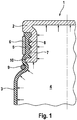
- Fig. 1 shows a schematic representation and in section a detail of a first embodiment of an air spring 1, which is clamped with an air spring piston, not shown, and an air spring cover 2 between the chassis and vehicle body of a motor vehicle.
- the air spring 1 has an air spring cover 2 and air spring piston sealingly mounted air spring bellows 3 made of elastomeric material which at least partially limits a working space 4 filled with compressed air and rolls to form at least one roll fold, not shown on the air spring piston.
- an end portion 5 of the air spring bellows 3 is fixed by means of a clamping ring 6 to a clamping portion 7 of the air spring cover 2. Due to the internal pressure and the resulting, indicated by arrows forces in the working space 4 of the air spring 1, the clamping connection between air bag 3 and air spring cover 2 is heavily loaded.
- the clamping portion 7 has a plurality of circumferential grooves 8, in which the material of the air spring bellows 3 when pressing the clamping ring 6 penetrates. These serve on the one hand to complicate the extraction of the air spring bellows 3 from the clamp connection, on the other hand, this improves the tightness in the terminal area with large temperature fluctuations.
- a further ring 9 is arranged to relieve the clamping ring 6 in the end region 5 of the air spring bellows 3 and outside of the clamping section 7. Its inner diameter substantially corresponds to an inner diameter of the clamping ring 6. This allows a recording of the radial loads through the further ring 9, which is referred to below as a relief ring, so that the clamping ring 6 significantly relieved and that the pressure of the clamping ring 6 is not reduced.
- the relief ring 9 is placed in a simple and cost-effective manner, at least during the first phase of inflation of the air spring 1 manually in position.
- the relief ring 9 before inflating the air spring 1 manually from below to the clamping ring 6 and in this example shown to a circumferential bead 10 of the clamping portion. 7 together.
- the bellows diameter increases and keeps the relief ring 9 initially by friction against gravity, so that the relief ring 9 no longer falls in the drawing down and manual positioning is no longer necessary.
- the relief ring 9 is thus positioned by means of the air pressure in the working space 4 on the air spring bellows 3.
- the bellows diameter increases further, so that the air bag of its own up the relief ring 9 presses up against the clamping ring 6 and the bead 10.
- a second and a third exemplary embodiment of the invention provide that the relief ring 9 is positioned on the air spring bellows 3 by means of an inner ring 11 or 12.
- the inner ring 11 or 12 is positioned in the air spring bellows 3 on the bead 10 of the clamping section 7, to which the relief ring 9 is pressed radially from the outside via the air spring bellows 3.
- the diameter of the relief ring 9 will initially be greater than its final diameter.
- the relief ring 9 is thus plastically deformed in this embodiment in the radial direction and pressed on the inner ring 11 and 12 respectively.
- the inner ring 11 and 12 have different, adapted to the shape of the relief ring 9 embodiments.
- the air spring bellows 3 may further comprise according to other alternative embodiments, for example, vulcanized positioning means for positioning the relief ring 9, whereby the assembly of the relief ring 9 can be substantially simplified.
- Conceivable here are about as individual, distributed on the air bag 3 vulcanized Kunststoffnasen which allow positioning of the relief ring 9 even with still unpressurized air bag 3, without the relief ring 9 drops.
- the air spring bellows 3 may have at least one circumferential bulge for positioning the relief ring 9.
Description
- Die Erfindung betrifft eine Luftfeder, insbesondere für Fahrzeuge, die mit einem Luftfederkolben und einem Luftfederdeckel zwischen Fahrwerk und Fahrzeugkarosserie eines Kraftfahrzeuges eingespannt ist, mit einem an Luftfederdeckel und Luftfederkolben dichtend befestigten Luftfederbalg aus elastomerem Material, welcher einen mit Druckluft gefüllten Arbeitsraum wenigstens teilweise begrenzt und der unter Ausbildung wenigstens einer Rollfalte an dem Luftfederkolben abrollt, wobei ein Endbereich des Luftfederbalges mittels eines Spannringes an einem Klemmabschnitt des Luftfederdeckels befestigt ist.
- Luftfedereinrichtungen, auch kurz Luftfedern genannt, die zwischen Fahrwerk und Karosserie eingespannt sind und einen Luftfederbalg aufweisen, der wiederum zwischen den Luftfederbauteilen Luftfederdeckel und Luftfederkolben befestigt ist, sind in einer Vielzahl von Ausführungen bekannt. Die Luftfeder steht im Betrieb unter einem inneren Überdruck. Der Luftfederbalg rollt unter Last und bei Federbewegungen unter Bildung einer Rollfalte auf der Außenkontur wenigstens eines Luftfederkolbens ab. Eine derartige Luftfeder wird häufig in Straßen- oder Schienenfahrzeugen eingesetzt, um eine komfortable Federung zu erreichen.
- Dabei existieren sowohl Luftfedern, bei denen der Luftfederbalg nur einseitig eine Rollfalte bildet, nämlich in der Regel auf dem Luftfederkolben, als auch Luftfedern, bei denen der Luftfederbalg unter Bildung einer beidseitigen (Roll-) Falte zwischen Luftfederdeckel und Luftfederkolben eingespannt ist.
- Für die Befestigung des Endbereiches des Luftfederbalges an dem Luftfederdeckel werden in der Regel radial plastisch verformbare Spannringe eingesetzt, welche den Endbereich des Luftfederbalges am Klemmabschnitt des Luftfederdeckels form- und reibschlüssig verspannen.
Durch den inneren Überdruck und die daraus resultierenden Kräfte im Arbeitsraum der Luftfeder wird die Klemmverbindung zwischen Luftfederbalg und Luftfederdeckel bzw. Luftfederkolben jedoch stark belastet, so dass die Gefahr besteht, dass das Ende des Luftfederbalges aus der Klemmung, d.h. unter dem Spannring herausgezogen wird. Zudem verringert sich insbesondere bei großen Temperaturschwankungen die Dichtigkeit im Klemmbereich. Radiale Kraftkomponenten sorgen ferner dafür, dass die Balgpressung reduziert wird, da der Luftfederbalg unter Druckbeaufschlagung eine Aufweitung des Spannringes erzeugt.
Zur Befestigung des Luftfederbalges an einem der Luftfederbauteilen ist eine Vielzahl von Befestigungsvariationen bekannt.US 6,637,733 offenbart eine Luftfeder mit einem beispielhaften Befestigungselement gemäß des Oberbegriffs des Anspruchs 1. Beispielsweise beschreibt dieDE 100 50 777 A1 eine Luftfeder mit einem konvex ausgebildeten Klemmbereich des Luftfederdeckels, auf welchem ein konkav ausgebildeter Klemmring aufgepresst ist. Es hat sich jedoch herausgestellt, dass bei den bekannten Klemmverbindungen die beschriebenen Probleme nur bedingt gelöst werden können.
Der Erfindung liegt die Aufgabe zugrunde, eine dahingehend verbesserte Luftfeder bereitzustellen, bei welcher ein Herausziehen des Luftfederbalges aus der Klemmung verhindert oder zumindest deutlich erschwert wird und deren Dichtigkeit sichergestellt werden kann. - Die der Erfindung zugrunde liegende Aufgabe wird mit den Merkmalen des unabhängigen Patentanspruchs 1 gelöst. Bevorzugte Ausführungsformen der Erfindung sind in den abhängigen Patentansprüchen angegeben.
- Erfindungsgemäß ist ein weiterer Ring vorgesehen, welcher zur Entlastung des Spannringes im Endbereich des Luftfederbalges und außerhalb des Klemmabschnittes angeordnet ist, wobei dessen Innendurchmesser im Wesentlichen einem Innendurchmesser des Spannringes entspricht. Der Entlastungsring kann die Radialbelastungen aufnehmen, so dass der Spannring deutlich entlastet wird. Hierdurch kann sichergestellt werden, dass die Pressung des Spannringes nicht reduziert wird. Ferner muss ein Herausziehen des Luftfederbalges aus der Klemmung nicht befürchtet werden.
Gemäß einer vorteilhaften Ausführungsform kann der Entlastungsring in einfacher und kostengünstiger Weise mittels Luftdruck in dem Arbeitsraum auf dem Luftfederbalg positioniert vorgesehen sein. - Eine alternative Ausführungsform der Erfindung sieht dagegen vor, dass der Entlastungsring mittels eines Innenringes auf dem Luftfederbalg positioniert vorgesehen ist. Hierzu ist der Entlastungsring auf den Innenring aufgepresst vorgesehen.
- Gemäß einer weiteren Ausführungsform weist der Luftfederbalg anvulkanisierte Positionierungsmittel zur Positionierung des Entlastungsringes auf, wodurch die Montage des Entlastungsringes wesentlich vereinfacht werden kann.
- Vorzugsweise weist der Luftfederbalg wenigstens einen umlaufenden Wulst zur Positionierung des Entlastungsringes auf.
- Alternativ können zur Positionierung des Entlastungsringes an den Luftfederbalg mehrere Gumminasen anvulkanisiert vorgesehen sein.
- Weitere Merkmale, Vorteile und Anwendungsmöglichkeiten der Erfindung gehen aus den Unteransprüchen und der nachfolgenden Beschreibung von Ausführungsbeispielen sowie anhand der Zeichnung hervor.
- Es zeigt jeweils stark schematisiert sowie im Schnitt:
-
Figur 1 : einen Ausschnitt eines ersten Ausführungsbeispiels einer erfindungsgemäßen Luftfeder; -
Figur 2 : einen Ausschnitt eines zweiten Ausführungsbeispiels einer erfindungsgemäßen Luftfeder und -
Figur 3 : einen Ausschnitt eines dritten Ausführungsbeispiels einer erfindungsgemäßen Luftfeder. -
Fig. 1 zeigt in schematischer Darstellung und im Schnitt einen Ausschnitt eines ersten Ausführungsbeispiels einer Luftfeder 1, die mit einem nicht gezeigten Luftfederkolben und einem Luftfederdeckel 2 zwischen Fahrwerk und Fahrzeugkarosserie eines Kraftfahrzeuges eingespannt ist. - Die Luftfeder 1 weist einen an Luftfederdeckel 2 und Luftfederkolben dichtend befestigten Luftfederbalg 3 aus elastomerem Material auf, welcher einen mit Druckluft gefüllten Arbeitsraum 4 wenigstens teilweise begrenzt und der unter Ausbildung wenigstens einer nicht gezeigten Rollfalte an dem Luftfederkolben abrollt.
- Wie in der Figur ersichtlich ist, ist ein Endbereich 5 des Luftfederbalges 3 mittels eines Spannringes 6 an einem Klemmabschnitt 7 des Luftfederdeckels 2 befestigt. Durch den inneren Überdruck und die daraus resultierenden, durch Pfeile angedeuteten Kräfte im Arbeitsraum 4 der Luftfeder 1 wird die Klemmverbindung zwischen Luftfederbalg 3 und Luftfederdeckel 2 stark belastet.
- Daher weist der Klemmabschnitt 7 mehrere umlaufende Nuten 8 auf, in welche das Material des Luftfederbalges 3 beim Verpressen des Spannringes 6 eindringt. Diese dienen zum einen dem Erschweren des Herausziehens des Luftfederbalges 3 aus der Klemmverbindung, zum anderen verbessert sich hierdurch bei großen Temperaturschwankungen die Dichtigkeit im Klemmbereich.
- Um die Gefahr des Herausziehens zu eliminieren sowie die Dichtigkeit der Klemmverbindung sicherzustellen, ist ein weiterer Ring 9 zur Entlastung des Spannringes 6 im Endbereich 5 des Luftfederbalges 3 und außerhalb des Klemmabschnittes 7 angeordnet. Dessen Innendurchmesser entspricht im Wesentlichen einem Innendurchmesser des Spannringes 6. Dies ermöglicht eine Aufnahme der Radialbelastungen durch den weiteren Ring 9, der nachfolgend als Entlastungsring bezeichnet wird, so dass der Spannring 6 deutlich entlastet und dass die Pressung des Spannringes 6 nicht reduziert wird.
- Bei der gezeigten Ausführungsform wird der Entlastungsring 9 in einfacher und kostengünstiger Weise zumindest während der ersten Phase des Aufblasens der Luftfeder 1 manuell in Position gebracht.
- Hierzu wird der Entlastungsring 9 vor dem Aufblasen der Luftfeder 1 manuell von unten an den Spannring 6 bzw. in diesem gezeigten Beispiel an einen umlaufenden Wulst 10 des Klemmabschnittes 7 gefügt. Durch das Aufblasen der Luftfeder 1 nimmt der Balgdurchmesser zu und hält den Entlastungsring 9 zunächst über Reibung gegen die Schwerkraft, so dass der Entlastungsring 9 nicht mehr in der Zeichnung nach unten fällt und eine manuelle Positionierung nicht mehr notwenig ist. Der Entlastungsring 9 wird also mittels des Luftdruckes in dem Arbeitsraum 4 auf dem Luftfederbalg 3 positioniert. Beim weiteren Aufblasen - entweder auf Auslieferdruck oder auf Betriebsdruck vergrößert sich der Balgdurchmesser weiter, so daß der Luftfederbalg von sich aus den Entlastungsring 9 nach oben gegen den Spannring 6 bzw. den Wulst 10 drückt.
- Gemäß den
Fig. 2 und 3 sehen ein zweites und ein drittes Ausführungsbeispiel der Erfindung dagegen vor, dass der Entlastungsring 9 mittels eines Innenringes 11 bzw. 12 auf dem Luftfederbalg 3 positioniert ist. - Der Innenring 11 bzw. 12 wird hierzu im Luftfederbalg 3 am Wulst 10 des Klemmabschnittes 7 positioniert, auf den man über den Luftfederbalg 3 den Entlastungsring 9 radial von außen aufpresst. In diesem Fall ist der Durchmesser des Entlastungsrings 9 zunächst größer sein als sein endgültiger Durchmesser. Der Entlastungsring 9 wird also bei diesem Ausführungsbeispiel in radialer Richtung plastisch verformt und auf den Innenring 11 bzw. 12 gedrückt. Wie aus den
Fig. 2 und 3 ersichtlich ist, kann der Innenring 11 bzw. 12 verschiedene, an die Form des Entlastungsringes 9 angepasste Ausgestaltungen aufweisen. - Der Luftfederbalg 3 kann ferner gemäß anderen alternativen Ausführungen beispielsweise anvulkanisierte Positionierungsmittel zur Positionierung des Entlastungsringes 9 aufweisen, wodurch die Montage des Entlastungsringes 9 wesentlich vereinfacht werden kann.
- Denkbar sind hier etwa einzelne, auf dem Luftfederbalg 3 verteilte anvulkanisierte Gumminasen, welche eine Positionierung des Entlastungsringes 9 auch bei noch drucklosem Luftfederbalg 3 erlauben, ohne dass der Entlastungsring 9 herunterfällt.
- Weiter kann der Luftfederbalg 3 wenigstens einen umlaufenden Wust zur Positionierung des Entlastungsringes 9 aufweisen.
-
- 1
- Luftfeder
- 2
- Luftfederdeckel
- 3
- Luftfederbalg
- 4
- Arbeitsraum
- 5
- Endbereich
- 6
- Spannring
- 7
- Klemmabschnitt
- 8
- Nut
- 9
- Ring/Entlastungsring
- 10
- Wulst
- 11
- Innenring
- 12
- Innenring
Claims (7)
- Luftfeder (1), insbesondere für Fahrzeuge, die mit einem Luftfederkolben und einem Luftfederdeckel (2) zwischen Fahrwerk und Fahrzeugkarosserie eines Kraftfahrzeuges eingespannt ist, mit einem an Luftfederdeckel (2) und Luftfederkolben dichtend befestigten Luftfederbalg (3) aus elastomerem Material, welcher einen mit Druckluft gefüllten Arbeitsraum (4) wenigstens teilweise begrenzt und der unter Ausbildung wenigstens einer Rollfalte an dem Luftfederkolben abrollt, wobei ein Endbereich (5) des Luftfederbalges (3) mittels eines Spannringes (6) an einem Klemmabschnitt (7) des Luftfederdeckels (2) befestigt ist, wobei ein Entlastungsring (9) vorgesehen ist, welcher zur Entlastung des Spannringes (6) im Endbereich (5) des Luftfederbalges (3) und außerhalb des Klemmabschnittes (7) angeordnet ist, wobei dessen Innendurchmesser im Wesentlichen einem Innendurchmesser des Spannringes (6) entspricht, dadurch gekennzeichnet, dass der Entlastungsring (9) an einen umlaufenden Wulst (10) des Klemmabschnittes (7) gefügt ist.
- Luftfeder nach Anspruch 1, dadurch gekennzeichnet, dass der Entlastungsring (9) mittels Luftdruck in dem Arbeitsraum (4) auf dem Luftfederbalg (3) positioniert vorgesehen ist.
- Luftfeder nach Anspruch 1, dadurch gekennzeichnet, dass der Entlastungsring (9) mittels eines Innenringes (11; 12) auf dem Luftfederbalg (3) positioniert vorgesehen ist.
- Luftfeder nach Anspruch 3, dadurch gekennzeichnet, dass der Entlastungsring (9) auf den Innenring (11;12) aufgepresst vorgesehen ist.
- Luftfeder nach Anspruch 1, dadurch gekennzeichnet, dass der Luftfederbalg (3) anvulkanisierte Positionierungsmittel zur Positionierung des Entlastungsringes (9) aufweist.
- Luftfeder nach Anspruch 5, dadurch gekennzeichnet, dass der Luftfederbalg (3) wenigstens einen umlaufenden Wulst zur Positionierung des Entlastungsringes (9) aufweist.
- Luftfeder nach Anspruch 5, dadurch gekennzeichnet, dass zur Positionierung des Entlastungsringes (9) an den Luftfederbalg (3) mehrere Gumminasen anvulkanisiert vorgesehen sind.
Applications Claiming Priority (2)
| Application Number | Priority Date | Filing Date | Title |
|---|---|---|---|
| DE102013206235.4A DE102013206235A1 (de) | 2013-04-09 | 2013-04-09 | Luftfeder, insbesondere für Fahrzeuge |
| PCT/EP2014/055893 WO2014166726A1 (de) | 2013-04-09 | 2014-03-25 | Luftfeder, insbesondere für fahrzeuge |
Publications (2)
| Publication Number | Publication Date |
|---|---|
| EP2984364A1 EP2984364A1 (de) | 2016-02-17 |
| EP2984364B1 true EP2984364B1 (de) | 2018-07-25 |
Family
ID=50588640
Family Applications (1)
| Application Number | Title | Priority Date | Filing Date |
|---|---|---|---|
| EP14719642.2A Active EP2984364B1 (de) | 2013-04-09 | 2014-03-25 | Luftfeder, insbesondere für fahrzeuge |
Country Status (5)
| Country | Link |
|---|---|
| US (1) | US9630468B2 (de) |
| EP (1) | EP2984364B1 (de) |
| CN (1) | CN105102845B (de) |
| DE (1) | DE102013206235A1 (de) |
| WO (1) | WO2014166726A1 (de) |
Families Citing this family (9)
| Publication number | Priority date | Publication date | Assignee | Title |
|---|---|---|---|---|
| US10578181B2 (en) * | 2015-11-09 | 2020-03-03 | Firestone Industrial Products Company, Llc | Flexible spring members as well as gas spring assemblies and methods of manufacture |
| DE102016212824A1 (de) | 2016-07-13 | 2018-01-18 | Continental Teves Ag & Co. Ohg | Luftfedereinheit |
| DE102016212825A1 (de) | 2016-07-13 | 2018-01-18 | Continental Teves Ag & Co. Ohg | Luftfeder mit Keilringbefestigung |
| DE102017222588A1 (de) | 2017-12-13 | 2019-06-13 | Contitech Luftfedersysteme Gmbh | Luftfeder |
| DE102018206903A1 (de) * | 2018-05-04 | 2019-11-07 | Continental Teves Ag & Co. Ohg | Luftfeder mit Vulkanisationsanbindung |
| CN109990033A (zh) * | 2019-04-20 | 2019-07-09 | 安路普(北京)汽车技术有限公司 | 一种活塞底座及空气弹簧 |
| CN112659835B (zh) * | 2021-01-04 | 2022-12-16 | 青岛博锐智远减振科技有限公司 | 空气弹簧及多连杆独立悬架 |
| CN114227245B (zh) * | 2021-12-13 | 2023-12-08 | 芜湖荣基密封系统有限公司 | 一种车用减震空气弹簧组装设备和组装方法 |
| US20230191865A1 (en) * | 2021-12-20 | 2023-06-22 | Continental Automotive Systems, Inc. | Airspring gaiter with sliding joint |
Family Cites Families (16)
| Publication number | Priority date | Publication date | Assignee | Title |
|---|---|---|---|---|
| DE4142561C2 (de) * | 1991-12-21 | 1995-04-27 | Continental Ag | Luftfeder mit einem wulstlosen Luftfederbalg aus elastomerem Werkstoff |
| DE19809658A1 (de) * | 1998-03-06 | 1999-09-16 | Continental Ag | Luftfeder mit einem Rollbalg und einem Abrollkolben und Verfahren zur Herstellung einer solchen Luftfeder |
| ATE310916T1 (de) | 1999-10-15 | 2005-12-15 | Freudenberg Carl Kg | Luftfederanordnung |
| DE10050777B4 (de) | 2000-10-13 | 2004-09-30 | Continental Aktiengesellschaft | Luftfeder und Verfahren zur Herstellung einer Luftfeder |
| DE50200186D1 (de) * | 2001-04-17 | 2004-02-05 | Phoenix Ag | Luftfederanordnung |
| US6637733B1 (en) * | 2002-06-12 | 2003-10-28 | Bfs Diversified Products, Llc | Air spring with vibration isolation |
| US6845973B2 (en) * | 2002-08-07 | 2005-01-25 | Bfs Diversified Products, Llc | Air spring with restraining cylinder |
| US7404547B2 (en) * | 2005-07-27 | 2008-07-29 | Bfs Diversified Products, Llc | Multi-component end member assembly and air spring assembly including the same |
| CN201096161Y (zh) * | 2007-10-22 | 2008-08-06 | 宁波美亚达汽车部件制造有限公司 | 一种多囊式橡胶空气弹簧 |
| JP5307486B2 (ja) * | 2008-09-16 | 2013-10-02 | 株式会社ブリヂストン | 空気ばね |
| DE102008055509A1 (de) | 2008-12-11 | 2010-06-17 | Contitech Luftfedersysteme Gmbh | Luftfeder |
| CN201434037Y (zh) * | 2009-06-10 | 2010-03-31 | 无锡锡南铸造机械有限公司 | 空气弹簧夹紧装置 |
| DE102012201104A1 (de) * | 2011-04-06 | 2013-04-11 | Continental Teves Ag & Co. Ohg | Luftfeder mit Hybridbalg |
| DE102012200388A1 (de) * | 2011-10-06 | 2013-04-11 | Continental Teves Ag & Co. Ohg | Luftfederdeckel mit zuschaltbarem Luftvolumen |
| DE102013203887A1 (de) * | 2012-05-08 | 2013-11-14 | Continental Teves Ag & Co. Ohg | Luftfeder und Verfahren zum Umschlagen eines Luftfederbalges einer Luftfeder |
| DE102014203733A1 (de) * | 2013-03-01 | 2014-09-04 | Firestone Industrial Products Company, Llc | Flexible federteile, gasfeder-anordnungen und verfahren |
-
2013
- 2013-04-09 DE DE102013206235.4A patent/DE102013206235A1/de not_active Withdrawn
-
2014
- 2014-03-25 EP EP14719642.2A patent/EP2984364B1/de active Active
- 2014-03-25 WO PCT/EP2014/055893 patent/WO2014166726A1/de active Application Filing
- 2014-03-25 US US14/780,691 patent/US9630468B2/en not_active Expired - Fee Related
- 2014-03-25 CN CN201480019990.1A patent/CN105102845B/zh not_active Expired - Fee Related
Non-Patent Citations (1)
| Title |
|---|
| None * |
Also Published As
| Publication number | Publication date |
|---|---|
| DE102013206235A1 (de) | 2014-10-09 |
| US9630468B2 (en) | 2017-04-25 |
| WO2014166726A1 (de) | 2014-10-16 |
| CN105102845A (zh) | 2015-11-25 |
| EP2984364A1 (de) | 2016-02-17 |
| CN105102845B (zh) | 2017-07-11 |
| US20160059655A1 (en) | 2016-03-03 |
Similar Documents
| Publication | Publication Date | Title |
|---|---|---|
| EP2984364B1 (de) | Luftfeder, insbesondere für fahrzeuge | |
| EP2847487B1 (de) | Luftfeder und verfahren zum umschlagen eines luftfederbalges einer luftfeder | |
| EP2089637B2 (de) | Luftfedereinrichtung | |
| EP1984647B1 (de) | LUFTFEDER MIT AUßENFÜHRUNG | |
| EP2550168B1 (de) | Luftfederanordnung mit integriertem steuerventil | |
| DE10122796B4 (de) | Kolben-Zylinderaggregat mit einem Faltbalg | |
| EP2780607B1 (de) | Luftfeder | |
| EP1031756B1 (de) | Befestigung eines Luftfeder-Rollbalges an einem Stützteil | |
| EP2803527A1 (de) | Fahrzeugschwingungsvorrichtung, Fahrzeugsitz und Fahrzeugkabine | |
| DE102015007743A1 (de) | Schublager und druckluftbeaufschlagter Stoßdämpfer | |
| DE102015216736B4 (de) | Federisolator für eine Fahrzeugradaufhängung | |
| DE102017116727A1 (de) | Sitzbaugruppe mit Energieabsorber | |
| DE102011009022A1 (de) | Konzentrischer Nehmerzylinder (CSC) | |
| EP2307751B1 (de) | An einem führungsholm einer scheibenbremse angeordneter faltenbalg | |
| EP2846061A1 (de) | Luftfeder und Tauchkolben für Luftfeder | |
| DE102012013964A1 (de) | Vorrichtung zum Andrücken einer Zahnstange an ein Ritzel | |
| EP2696095A1 (de) | Luftfeder mit Anschlüssen zur Befestigung der Enden eines Rollbalgs | |
| EP2060832A2 (de) | Klemmkontur für ein druckbeaufschlagbares Bauteil und Spannmittel dafür | |
| WO2014111183A1 (de) | Luftfeder | |
| WO2018146053A1 (de) | Zylinder-kolben-vorrichtung mit wenigstens einem innenrohr und wenigstens einem aussenrohr | |
| EP3779233B1 (de) | Luftfederbalg und verfahren zur herstellung eines solchen luftfederbalgs | |
| EP2496426B1 (de) | Luftfeder mit schaltventil zur restdruckhaltung | |
| DE102016212825A1 (de) | Luftfeder mit Keilringbefestigung | |
| DE102016212824A1 (de) | Luftfedereinheit | |
| DE102019209491A1 (de) | Luftfeder mit einer Kunststoffaußenführung |
Legal Events
| Date | Code | Title | Description |
|---|---|---|---|
| PUAI | Public reference made under article 153(3) epc to a published international application that has entered the european phase |
Free format text: ORIGINAL CODE: 0009012 |
|
| 17P | Request for examination filed |
Effective date: 20151109 |
|
| AK | Designated contracting states |
Kind code of ref document: A1 Designated state(s): AL AT BE BG CH CY CZ DE DK EE ES FI FR GB GR HR HU IE IS IT LI LT LU LV MC MK MT NL NO PL PT RO RS SE SI SK SM TR |
|
| AX | Request for extension of the european patent |
Extension state: BA ME |
|
| RIN1 | Information on inventor provided before grant (corrected) |
Inventor name: BINDER, KLAUS |
|
| DAX | Request for extension of the european patent (deleted) | ||
| STAA | Information on the status of an ep patent application or granted ep patent |
Free format text: STATUS: EXAMINATION IS IN PROGRESS |
|
| 17Q | First examination report despatched |
Effective date: 20170321 |
|
| RIC1 | Information provided on ipc code assigned before grant |
Ipc: B60G 11/27 20060101ALI20180112BHEP Ipc: F16F 9/04 20060101AFI20180112BHEP |
|
| GRAP | Despatch of communication of intention to grant a patent |
Free format text: ORIGINAL CODE: EPIDOSNIGR1 |
|
| STAA | Information on the status of an ep patent application or granted ep patent |
Free format text: STATUS: GRANT OF PATENT IS INTENDED |
|
| INTG | Intention to grant announced |
Effective date: 20180321 |
|
| GRAS | Grant fee paid |
Free format text: ORIGINAL CODE: EPIDOSNIGR3 |
|
| GRAA | (expected) grant |
Free format text: ORIGINAL CODE: 0009210 |
|
| STAA | Information on the status of an ep patent application or granted ep patent |
Free format text: STATUS: THE PATENT HAS BEEN GRANTED |
|
| AK | Designated contracting states |
Kind code of ref document: B1 Designated state(s): AL AT BE BG CH CY CZ DE DK EE ES FI FR GB GR HR HU IE IS IT LI LT LU LV MC MK MT NL NO PL PT RO RS SE SI SK SM TR |
|
| REG | Reference to a national code |
Ref country code: GB Ref legal event code: FG4D Free format text: NOT ENGLISH |
|
| REG | Reference to a national code |
Ref country code: CH Ref legal event code: EP |
|
| REG | Reference to a national code |
Ref country code: AT Ref legal event code: REF Ref document number: 1022111 Country of ref document: AT Kind code of ref document: T Effective date: 20180815 |
|
| REG | Reference to a national code |
Ref country code: IE Ref legal event code: FG4D Free format text: LANGUAGE OF EP DOCUMENT: GERMAN |
|
| REG | Reference to a national code |
Ref country code: DE Ref legal event code: R096 Ref document number: 502014008968 Country of ref document: DE |
|
| RAP2 | Party data changed (patent owner data changed or rights of a patent transferred) |
Owner name: CONTINENTAL TEVES AG & CO. OHG |
|
| REG | Reference to a national code |
Ref country code: NL Ref legal event code: MP Effective date: 20180725 |
|
| REG | Reference to a national code |
Ref country code: LT Ref legal event code: MG4D |
|
| PG25 | Lapsed in a contracting state [announced via postgrant information from national office to epo] |
Ref country code: NL Free format text: LAPSE BECAUSE OF FAILURE TO SUBMIT A TRANSLATION OF THE DESCRIPTION OR TO PAY THE FEE WITHIN THE PRESCRIBED TIME-LIMIT Effective date: 20180725 |
|
| PG25 | Lapsed in a contracting state [announced via postgrant information from national office to epo] |
Ref country code: IS Free format text: LAPSE BECAUSE OF FAILURE TO SUBMIT A TRANSLATION OF THE DESCRIPTION OR TO PAY THE FEE WITHIN THE PRESCRIBED TIME-LIMIT Effective date: 20181125 Ref country code: PL Free format text: LAPSE BECAUSE OF FAILURE TO SUBMIT A TRANSLATION OF THE DESCRIPTION OR TO PAY THE FEE WITHIN THE PRESCRIBED TIME-LIMIT Effective date: 20180725 Ref country code: RS Free format text: LAPSE BECAUSE OF FAILURE TO SUBMIT A TRANSLATION OF THE DESCRIPTION OR TO PAY THE FEE WITHIN THE PRESCRIBED TIME-LIMIT Effective date: 20180725 Ref country code: FI Free format text: LAPSE BECAUSE OF FAILURE TO SUBMIT A TRANSLATION OF THE DESCRIPTION OR TO PAY THE FEE WITHIN THE PRESCRIBED TIME-LIMIT Effective date: 20180725 Ref country code: LT Free format text: LAPSE BECAUSE OF FAILURE TO SUBMIT A TRANSLATION OF THE DESCRIPTION OR TO PAY THE FEE WITHIN THE PRESCRIBED TIME-LIMIT Effective date: 20180725 Ref country code: SE Free format text: LAPSE BECAUSE OF FAILURE TO SUBMIT A TRANSLATION OF THE DESCRIPTION OR TO PAY THE FEE WITHIN THE PRESCRIBED TIME-LIMIT Effective date: 20180725 Ref country code: GR Free format text: LAPSE BECAUSE OF FAILURE TO SUBMIT A TRANSLATION OF THE DESCRIPTION OR TO PAY THE FEE WITHIN THE PRESCRIBED TIME-LIMIT Effective date: 20181026 Ref country code: BG Free format text: LAPSE BECAUSE OF FAILURE TO SUBMIT A TRANSLATION OF THE DESCRIPTION OR TO PAY THE FEE WITHIN THE PRESCRIBED TIME-LIMIT Effective date: 20181025 Ref country code: NO Free format text: LAPSE BECAUSE OF FAILURE TO SUBMIT A TRANSLATION OF THE DESCRIPTION OR TO PAY THE FEE WITHIN THE PRESCRIBED TIME-LIMIT Effective date: 20181025 |
|
| PG25 | Lapsed in a contracting state [announced via postgrant information from national office to epo] |
Ref country code: HR Free format text: LAPSE BECAUSE OF FAILURE TO SUBMIT A TRANSLATION OF THE DESCRIPTION OR TO PAY THE FEE WITHIN THE PRESCRIBED TIME-LIMIT Effective date: 20180725 Ref country code: LV Free format text: LAPSE BECAUSE OF FAILURE TO SUBMIT A TRANSLATION OF THE DESCRIPTION OR TO PAY THE FEE WITHIN THE PRESCRIBED TIME-LIMIT Effective date: 20180725 Ref country code: AL Free format text: LAPSE BECAUSE OF FAILURE TO SUBMIT A TRANSLATION OF THE DESCRIPTION OR TO PAY THE FEE WITHIN THE PRESCRIBED TIME-LIMIT Effective date: 20180725 |
|
| REG | Reference to a national code |
Ref country code: DE Ref legal event code: R097 Ref document number: 502014008968 Country of ref document: DE |
|
| PG25 | Lapsed in a contracting state [announced via postgrant information from national office to epo] |
Ref country code: CZ Free format text: LAPSE BECAUSE OF FAILURE TO SUBMIT A TRANSLATION OF THE DESCRIPTION OR TO PAY THE FEE WITHIN THE PRESCRIBED TIME-LIMIT Effective date: 20180725 Ref country code: IT Free format text: LAPSE BECAUSE OF FAILURE TO SUBMIT A TRANSLATION OF THE DESCRIPTION OR TO PAY THE FEE WITHIN THE PRESCRIBED TIME-LIMIT Effective date: 20180725 Ref country code: ES Free format text: LAPSE BECAUSE OF FAILURE TO SUBMIT A TRANSLATION OF THE DESCRIPTION OR TO PAY THE FEE WITHIN THE PRESCRIBED TIME-LIMIT Effective date: 20180725 Ref country code: RO Free format text: LAPSE BECAUSE OF FAILURE TO SUBMIT A TRANSLATION OF THE DESCRIPTION OR TO PAY THE FEE WITHIN THE PRESCRIBED TIME-LIMIT Effective date: 20180725 Ref country code: EE Free format text: LAPSE BECAUSE OF FAILURE TO SUBMIT A TRANSLATION OF THE DESCRIPTION OR TO PAY THE FEE WITHIN THE PRESCRIBED TIME-LIMIT Effective date: 20180725 |
|
| PGFP | Annual fee paid to national office [announced via postgrant information from national office to epo] |
Ref country code: FR Payment date: 20190322 Year of fee payment: 6 |
|
| PG25 | Lapsed in a contracting state [announced via postgrant information from national office to epo] |
Ref country code: SK Free format text: LAPSE BECAUSE OF FAILURE TO SUBMIT A TRANSLATION OF THE DESCRIPTION OR TO PAY THE FEE WITHIN THE PRESCRIBED TIME-LIMIT Effective date: 20180725 Ref country code: SM Free format text: LAPSE BECAUSE OF FAILURE TO SUBMIT A TRANSLATION OF THE DESCRIPTION OR TO PAY THE FEE WITHIN THE PRESCRIBED TIME-LIMIT Effective date: 20180725 Ref country code: DK Free format text: LAPSE BECAUSE OF FAILURE TO SUBMIT A TRANSLATION OF THE DESCRIPTION OR TO PAY THE FEE WITHIN THE PRESCRIBED TIME-LIMIT Effective date: 20180725 |
|
| PLBE | No opposition filed within time limit |
Free format text: ORIGINAL CODE: 0009261 |
|
| STAA | Information on the status of an ep patent application or granted ep patent |
Free format text: STATUS: NO OPPOSITION FILED WITHIN TIME LIMIT |
|
| 26N | No opposition filed |
Effective date: 20190426 |
|
| PG25 | Lapsed in a contracting state [announced via postgrant information from national office to epo] |
Ref country code: SI Free format text: LAPSE BECAUSE OF FAILURE TO SUBMIT A TRANSLATION OF THE DESCRIPTION OR TO PAY THE FEE WITHIN THE PRESCRIBED TIME-LIMIT Effective date: 20180725 |
|
| PG25 | Lapsed in a contracting state [announced via postgrant information from national office to epo] |
Ref country code: MC Free format text: LAPSE BECAUSE OF FAILURE TO SUBMIT A TRANSLATION OF THE DESCRIPTION OR TO PAY THE FEE WITHIN THE PRESCRIBED TIME-LIMIT Effective date: 20180725 |
|
| REG | Reference to a national code |
Ref country code: CH Ref legal event code: PL |
|
| GBPC | Gb: european patent ceased through non-payment of renewal fee |
Effective date: 20190325 |
|
| PG25 | Lapsed in a contracting state [announced via postgrant information from national office to epo] |
Ref country code: LU Free format text: LAPSE BECAUSE OF NON-PAYMENT OF DUE FEES Effective date: 20190325 |
|
| REG | Reference to a national code |
Ref country code: BE Ref legal event code: MM Effective date: 20190331 |
|
| PG25 | Lapsed in a contracting state [announced via postgrant information from national office to epo] |
Ref country code: LI Free format text: LAPSE BECAUSE OF NON-PAYMENT OF DUE FEES Effective date: 20190331 Ref country code: CH Free format text: LAPSE BECAUSE OF NON-PAYMENT OF DUE FEES Effective date: 20190331 Ref country code: GB Free format text: LAPSE BECAUSE OF NON-PAYMENT OF DUE FEES Effective date: 20190325 Ref country code: IE Free format text: LAPSE BECAUSE OF NON-PAYMENT OF DUE FEES Effective date: 20190325 |
|
| PG25 | Lapsed in a contracting state [announced via postgrant information from national office to epo] |
Ref country code: BE Free format text: LAPSE BECAUSE OF NON-PAYMENT OF DUE FEES Effective date: 20190331 |
|
| PG25 | Lapsed in a contracting state [announced via postgrant information from national office to epo] |
Ref country code: TR Free format text: LAPSE BECAUSE OF FAILURE TO SUBMIT A TRANSLATION OF THE DESCRIPTION OR TO PAY THE FEE WITHIN THE PRESCRIBED TIME-LIMIT Effective date: 20180725 |
|
| PG25 | Lapsed in a contracting state [announced via postgrant information from national office to epo] |
Ref country code: PT Free format text: LAPSE BECAUSE OF FAILURE TO SUBMIT A TRANSLATION OF THE DESCRIPTION OR TO PAY THE FEE WITHIN THE PRESCRIBED TIME-LIMIT Effective date: 20181125 Ref country code: MT Free format text: LAPSE BECAUSE OF FAILURE TO SUBMIT A TRANSLATION OF THE DESCRIPTION OR TO PAY THE FEE WITHIN THE PRESCRIBED TIME-LIMIT Effective date: 20180725 |
|
| REG | Reference to a national code |
Ref country code: AT Ref legal event code: MM01 Ref document number: 1022111 Country of ref document: AT Kind code of ref document: T Effective date: 20190325 |
|
| PG25 | Lapsed in a contracting state [announced via postgrant information from national office to epo] |
Ref country code: AT Free format text: LAPSE BECAUSE OF NON-PAYMENT OF DUE FEES Effective date: 20190325 |
|
| PG25 | Lapsed in a contracting state [announced via postgrant information from national office to epo] |
Ref country code: FR Free format text: LAPSE BECAUSE OF NON-PAYMENT OF DUE FEES Effective date: 20200331 |
|
| PG25 | Lapsed in a contracting state [announced via postgrant information from national office to epo] |
Ref country code: CY Free format text: LAPSE BECAUSE OF FAILURE TO SUBMIT A TRANSLATION OF THE DESCRIPTION OR TO PAY THE FEE WITHIN THE PRESCRIBED TIME-LIMIT Effective date: 20180725 |
|
| PG25 | Lapsed in a contracting state [announced via postgrant information from national office to epo] |
Ref country code: HU Free format text: LAPSE BECAUSE OF FAILURE TO SUBMIT A TRANSLATION OF THE DESCRIPTION OR TO PAY THE FEE WITHIN THE PRESCRIBED TIME-LIMIT; INVALID AB INITIO Effective date: 20140325 |
|
| PG25 | Lapsed in a contracting state [announced via postgrant information from national office to epo] |
Ref country code: MK Free format text: LAPSE BECAUSE OF FAILURE TO SUBMIT A TRANSLATION OF THE DESCRIPTION OR TO PAY THE FEE WITHIN THE PRESCRIBED TIME-LIMIT Effective date: 20180725 |
|
| REG | Reference to a national code |
Ref country code: DE Ref legal event code: R081 Ref document number: 502014008968 Country of ref document: DE Owner name: CONTINENTAL AUTOMOTIVE TECHNOLOGIES GMBH, DE Free format text: FORMER OWNER: CONTINENTAL TEVES AG & CO. OHG, 60488 FRANKFURT, DE |
|
| PGFP | Annual fee paid to national office [announced via postgrant information from national office to epo] |
Ref country code: DE Payment date: 20230331 Year of fee payment: 10 |