EP2982999B1 - Batterieüberwachungssystem und einstellverfahren für identifizierungsinformation - Google Patents
Batterieüberwachungssystem und einstellverfahren für identifizierungsinformation Download PDFInfo
- Publication number
- EP2982999B1 EP2982999B1 EP14779035.6A EP14779035A EP2982999B1 EP 2982999 B1 EP2982999 B1 EP 2982999B1 EP 14779035 A EP14779035 A EP 14779035A EP 2982999 B1 EP2982999 B1 EP 2982999B1
- Authority
- EP
- European Patent Office
- Prior art keywords
- identifying information
- identifying
- information
- monitoring
- unit
- Prior art date
- Legal status (The legal status is an assumption and is not a legal conclusion. Google has not performed a legal analysis and makes no representation as to the accuracy of the status listed.)
- Active
Links
Images
Classifications
-
- B—PERFORMING OPERATIONS; TRANSPORTING
- B60—VEHICLES IN GENERAL
- B60L—PROPULSION OF ELECTRICALLY-PROPELLED VEHICLES; SUPPLYING ELECTRIC POWER FOR AUXILIARY EQUIPMENT OF ELECTRICALLY-PROPELLED VEHICLES; ELECTRODYNAMIC BRAKE SYSTEMS FOR VEHICLES IN GENERAL; MAGNETIC SUSPENSION OR LEVITATION FOR VEHICLES; MONITORING OPERATING VARIABLES OF ELECTRICALLY-PROPELLED VEHICLES; ELECTRIC SAFETY DEVICES FOR ELECTRICALLY-PROPELLED VEHICLES
- B60L58/00—Methods or circuit arrangements for monitoring or controlling batteries or fuel cells, specially adapted for electric vehicles
- B60L58/10—Methods or circuit arrangements for monitoring or controlling batteries or fuel cells, specially adapted for electric vehicles for monitoring or controlling batteries
- B60L58/12—Methods or circuit arrangements for monitoring or controlling batteries or fuel cells, specially adapted for electric vehicles for monitoring or controlling batteries responding to state of charge [SoC]
-
- B—PERFORMING OPERATIONS; TRANSPORTING
- B60—VEHICLES IN GENERAL
- B60L—PROPULSION OF ELECTRICALLY-PROPELLED VEHICLES; SUPPLYING ELECTRIC POWER FOR AUXILIARY EQUIPMENT OF ELECTRICALLY-PROPELLED VEHICLES; ELECTRODYNAMIC BRAKE SYSTEMS FOR VEHICLES IN GENERAL; MAGNETIC SUSPENSION OR LEVITATION FOR VEHICLES; MONITORING OPERATING VARIABLES OF ELECTRICALLY-PROPELLED VEHICLES; ELECTRIC SAFETY DEVICES FOR ELECTRICALLY-PROPELLED VEHICLES
- B60L3/00—Electric devices on electrically-propelled vehicles for safety purposes; Monitoring operating variables, e.g. speed, deceleration or energy consumption
- B60L3/0023—Detecting, eliminating, remedying or compensating for drive train abnormalities, e.g. failures within the drive train
- B60L3/0084—Detecting, eliminating, remedying or compensating for drive train abnormalities, e.g. failures within the drive train relating to control modules
-
- B—PERFORMING OPERATIONS; TRANSPORTING
- B60—VEHICLES IN GENERAL
- B60L—PROPULSION OF ELECTRICALLY-PROPELLED VEHICLES; SUPPLYING ELECTRIC POWER FOR AUXILIARY EQUIPMENT OF ELECTRICALLY-PROPELLED VEHICLES; ELECTRODYNAMIC BRAKE SYSTEMS FOR VEHICLES IN GENERAL; MAGNETIC SUSPENSION OR LEVITATION FOR VEHICLES; MONITORING OPERATING VARIABLES OF ELECTRICALLY-PROPELLED VEHICLES; ELECTRIC SAFETY DEVICES FOR ELECTRICALLY-PROPELLED VEHICLES
- B60L3/00—Electric devices on electrically-propelled vehicles for safety purposes; Monitoring operating variables, e.g. speed, deceleration or energy consumption
- B60L3/12—Recording operating variables ; Monitoring of operating variables
-
- B—PERFORMING OPERATIONS; TRANSPORTING
- B60—VEHICLES IN GENERAL
- B60L—PROPULSION OF ELECTRICALLY-PROPELLED VEHICLES; SUPPLYING ELECTRIC POWER FOR AUXILIARY EQUIPMENT OF ELECTRICALLY-PROPELLED VEHICLES; ELECTRODYNAMIC BRAKE SYSTEMS FOR VEHICLES IN GENERAL; MAGNETIC SUSPENSION OR LEVITATION FOR VEHICLES; MONITORING OPERATING VARIABLES OF ELECTRICALLY-PROPELLED VEHICLES; ELECTRIC SAFETY DEVICES FOR ELECTRICALLY-PROPELLED VEHICLES
- B60L58/00—Methods or circuit arrangements for monitoring or controlling batteries or fuel cells, specially adapted for electric vehicles
- B60L58/10—Methods or circuit arrangements for monitoring or controlling batteries or fuel cells, specially adapted for electric vehicles for monitoring or controlling batteries
- B60L58/18—Methods or circuit arrangements for monitoring or controlling batteries or fuel cells, specially adapted for electric vehicles for monitoring or controlling batteries of two or more battery modules
- B60L58/21—Methods or circuit arrangements for monitoring or controlling batteries or fuel cells, specially adapted for electric vehicles for monitoring or controlling batteries of two or more battery modules having the same nominal voltage
-
- G—PHYSICS
- G01—MEASURING; TESTING
- G01R—MEASURING ELECTRIC VARIABLES; MEASURING MAGNETIC VARIABLES
- G01R31/00—Arrangements for testing electric properties; Arrangements for locating electric faults; Arrangements for electrical testing characterised by what is being tested not provided for elsewhere
- G01R31/36—Arrangements for testing, measuring or monitoring the electrical condition of accumulators or electric batteries, e.g. capacity or state of charge [SoC]
- G01R31/392—Determining battery ageing or deterioration, e.g. state of health
-
- G—PHYSICS
- G01—MEASURING; TESTING
- G01R—MEASURING ELECTRIC VARIABLES; MEASURING MAGNETIC VARIABLES
- G01R31/00—Arrangements for testing electric properties; Arrangements for locating electric faults; Arrangements for electrical testing characterised by what is being tested not provided for elsewhere
- G01R31/36—Arrangements for testing, measuring or monitoring the electrical condition of accumulators or electric batteries, e.g. capacity or state of charge [SoC]
- G01R31/396—Acquisition or processing of data for testing or for monitoring individual cells or groups of cells within a battery
-
- H—ELECTRICITY
- H01—ELECTRIC ELEMENTS
- H01M—PROCESSES OR MEANS, e.g. BATTERIES, FOR THE DIRECT CONVERSION OF CHEMICAL ENERGY INTO ELECTRICAL ENERGY
- H01M10/00—Secondary cells; Manufacture thereof
- H01M10/42—Methods or arrangements for servicing or maintenance of secondary cells or secondary half-cells
- H01M10/48—Accumulators combined with arrangements for measuring, testing or indicating the condition of cells, e.g. the level or density of the electrolyte
- H01M10/482—Accumulators combined with arrangements for measuring, testing or indicating the condition of cells, e.g. the level or density of the electrolyte for several batteries or cells simultaneously or sequentially
-
- H—ELECTRICITY
- H04—ELECTRIC COMMUNICATION TECHNIQUE
- H04L—TRANSMISSION OF DIGITAL INFORMATION, e.g. TELEGRAPHIC COMMUNICATION
- H04L61/00—Network arrangements, protocols or services for addressing or naming
- H04L61/50—Address allocation
- H04L61/5038—Address allocation for local use, e.g. in LAN or USB networks, or in a controller area network [CAN]
-
- H—ELECTRICITY
- H04—ELECTRIC COMMUNICATION TECHNIQUE
- H04L—TRANSMISSION OF DIGITAL INFORMATION, e.g. TELEGRAPHIC COMMUNICATION
- H04L61/00—Network arrangements, protocols or services for addressing or naming
- H04L61/50—Address allocation
- H04L61/5092—Address allocation by self-assignment, e.g. picking addresses at random and testing if they are already in use
-
- B—PERFORMING OPERATIONS; TRANSPORTING
- B60—VEHICLES IN GENERAL
- B60L—PROPULSION OF ELECTRICALLY-PROPELLED VEHICLES; SUPPLYING ELECTRIC POWER FOR AUXILIARY EQUIPMENT OF ELECTRICALLY-PROPELLED VEHICLES; ELECTRODYNAMIC BRAKE SYSTEMS FOR VEHICLES IN GENERAL; MAGNETIC SUSPENSION OR LEVITATION FOR VEHICLES; MONITORING OPERATING VARIABLES OF ELECTRICALLY-PROPELLED VEHICLES; ELECTRIC SAFETY DEVICES FOR ELECTRICALLY-PROPELLED VEHICLES
- B60L2240/00—Control parameters of input or output; Target parameters
- B60L2240/40—Drive Train control parameters
- B60L2240/54—Drive Train control parameters related to batteries
- B60L2240/545—Temperature
-
- B—PERFORMING OPERATIONS; TRANSPORTING
- B60—VEHICLES IN GENERAL
- B60L—PROPULSION OF ELECTRICALLY-PROPELLED VEHICLES; SUPPLYING ELECTRIC POWER FOR AUXILIARY EQUIPMENT OF ELECTRICALLY-PROPELLED VEHICLES; ELECTRODYNAMIC BRAKE SYSTEMS FOR VEHICLES IN GENERAL; MAGNETIC SUSPENSION OR LEVITATION FOR VEHICLES; MONITORING OPERATING VARIABLES OF ELECTRICALLY-PROPELLED VEHICLES; ELECTRIC SAFETY DEVICES FOR ELECTRICALLY-PROPELLED VEHICLES
- B60L2240/00—Control parameters of input or output; Target parameters
- B60L2240/40—Drive Train control parameters
- B60L2240/54—Drive Train control parameters related to batteries
- B60L2240/547—Voltage
-
- B—PERFORMING OPERATIONS; TRANSPORTING
- B60—VEHICLES IN GENERAL
- B60L—PROPULSION OF ELECTRICALLY-PROPELLED VEHICLES; SUPPLYING ELECTRIC POWER FOR AUXILIARY EQUIPMENT OF ELECTRICALLY-PROPELLED VEHICLES; ELECTRODYNAMIC BRAKE SYSTEMS FOR VEHICLES IN GENERAL; MAGNETIC SUSPENSION OR LEVITATION FOR VEHICLES; MONITORING OPERATING VARIABLES OF ELECTRICALLY-PROPELLED VEHICLES; ELECTRIC SAFETY DEVICES FOR ELECTRICALLY-PROPELLED VEHICLES
- B60L2240/00—Control parameters of input or output; Target parameters
- B60L2240/40—Drive Train control parameters
- B60L2240/54—Drive Train control parameters related to batteries
- B60L2240/549—Current
-
- G—PHYSICS
- G01—MEASURING; TESTING
- G01R—MEASURING ELECTRIC VARIABLES; MEASURING MAGNETIC VARIABLES
- G01R31/00—Arrangements for testing electric properties; Arrangements for locating electric faults; Arrangements for electrical testing characterised by what is being tested not provided for elsewhere
- G01R31/36—Arrangements for testing, measuring or monitoring the electrical condition of accumulators or electric batteries, e.g. capacity or state of charge [SoC]
- G01R31/382—Arrangements for monitoring battery or accumulator variables, e.g. SoC
-
- Y—GENERAL TAGGING OF NEW TECHNOLOGICAL DEVELOPMENTS; GENERAL TAGGING OF CROSS-SECTIONAL TECHNOLOGIES SPANNING OVER SEVERAL SECTIONS OF THE IPC; TECHNICAL SUBJECTS COVERED BY FORMER USPC CROSS-REFERENCE ART COLLECTIONS [XRACs] AND DIGESTS
- Y02—TECHNOLOGIES OR APPLICATIONS FOR MITIGATION OR ADAPTATION AGAINST CLIMATE CHANGE
- Y02E—REDUCTION OF GREENHOUSE GAS [GHG] EMISSIONS, RELATED TO ENERGY GENERATION, TRANSMISSION OR DISTRIBUTION
- Y02E60/00—Enabling technologies; Technologies with a potential or indirect contribution to GHG emissions mitigation
- Y02E60/10—Energy storage using batteries
-
- Y—GENERAL TAGGING OF NEW TECHNOLOGICAL DEVELOPMENTS; GENERAL TAGGING OF CROSS-SECTIONAL TECHNOLOGIES SPANNING OVER SEVERAL SECTIONS OF THE IPC; TECHNICAL SUBJECTS COVERED BY FORMER USPC CROSS-REFERENCE ART COLLECTIONS [XRACs] AND DIGESTS
- Y02—TECHNOLOGIES OR APPLICATIONS FOR MITIGATION OR ADAPTATION AGAINST CLIMATE CHANGE
- Y02T—CLIMATE CHANGE MITIGATION TECHNOLOGIES RELATED TO TRANSPORTATION
- Y02T10/00—Road transport of goods or passengers
- Y02T10/60—Other road transportation technologies with climate change mitigation effect
- Y02T10/70—Energy storage systems for electromobility, e.g. batteries
Definitions
- the present invention discussed herein is related to a technology for monitoring states of a plurality of batteries.
- some battery-monitoring systems that monitor the state of each battery include control units that allow charging and discharging of each battery according to the monitoring result of each battery.
- the control unit requires identifying information that is individually allocated to each of a plurality of monitoring units that monitor the states of the batteries in order to obtain the monitoring result from each monitoring unit.
- the monitoring unit that corresponds to the battery after swapping or after replacement cannot communicate normally with the control unit.
- a power unit includes a plurality of battery modules.
- the battery management system includes a power source for a motor, the power source being constituted by a plurality of battery modules having battery cells, battery module status sensors mounted on the battery modules on the one to one basis, detecting voltages and temperatures of the battery modules, and a control unit judging statuses of the battery modules on the basis of data detected by the battery module status sensors.
- the battery module status sensors are mutually connected in series by a communication line for transmitting numbering data, and each battery module status sensor assigning itself with an ID code on the basis of ID information received from an upstream battery module status sensor, and transmitting the ID information as well as the ID code to a downstream battery module status sensor.
- the control unit is connected to the battery module status sensors via the communication line for transmitting the numbering data and a communication line for transmitting various data except for the numbering data, and locates an abnormal battery module on the basis of detection information received via the communication line for transmitting the numbering data and the communication line for transmitting various data except for the numbering data.
- the present invention aims to provide a battery-monitoring system and an identifying-information setting method that enable easy resetting of identifying information for a monitoring unit in a case in which monitoring units that monitor states of batteries that are connected in parallel are connected in series.
- resetting of identifying information for the monitoring units may be performed in an easier way in comparison with the case of resetting identifying information for all the monitoring units after replacement of the monitoring unit.
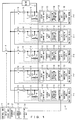
- FIG. 1 is a diagram illustrating a battery-monitoring system of an embodiment.
- the battery-monitoring system 1 illustrated in FIG. 1 includes a plurality of battery modules 2 (2-1 to 2-5), a control unit (battery ECU) 3, and a main relay 4. Note that the battery-monitoring system 1 is mounted on a vehicle such as an electric forklift truck, a hybrid vehicle, or an electric vehicle. In addition, the number of battery modules 2 is not limited to 5.
- Each of the battery modules 2-1 to 2-5 includes a battery 5, a relay 6, a voltage detection unit 7, a current detection unit 8, a temperature detection unit 9, and a monitoring unit (monitoring ECU) 10.
- the battery 5 is a rechargeable battery, and is, for example, a lithium-ion secondary battery or a nickel hydride battery.
- the battery 5 may be configured by including a plurality of batteries that are connected in series. The batteries 5 are connected in parallel and supply power to a load 11.
- the relay 6 is provided between the main relay 4 and the battery 5. When the main relay 4 is turned on while the relay 6 is on, power may be supplied from the battery 5 to the load 11.
- the voltage detection unit 7 detects the voltage of the battery 5 and is, for example, a voltmeter.
- the current detection unit 8 detects a current that flows to the battery 5 during charging and a current that flows from the battery 5 during discharging, and is, for example, an ammeter.
- the temperature detection unit 9 detects ambient temperature of the battery 5, and is, for example, a thermistor.
- the monitoring unit 10 includes a relay control unit 12, a storage unit 13, an identifying-information setting unit 14, and a communication unit 15.
- the relay control unit 12, the identifying-information setting unit 14, and the communication unit 15 are configured, for example, by using a CPU (Central Processing Unit), a multi-core CPU, a programmable device (FPGA (Field Programmable Gate Array), PLD (Programmable Logic Device), etc.) and are realized by reading and executing by the CPU, the programmable device, or the PLD a program that has been stored in the storage unit 13.
- a CPU Central Processing Unit
- FPGA Field Programmable Gate Array
- PLD Programmable Logic Device
- the relay control unit 12 controls on and off of the relay 6.
- the storage unit 13 is, for example, a ROM (Read Only Memory) or a RAM (Random Access Memory), and stores various pieces of information and various programs.
- the identifying-information setting unit 14 sets identifying information for itself and causes the storage unit 13 to store therein the identifying information. For example, in a case in which five pieces of identifying information, "101", “102", “103”, “104", and “105" are allocated to the battery modules 2-1 to 2-5, respectively, the identifying-information setting unit 14 of the leading battery module 2-1 allocates "101" as identifying information for itself and causes the storage unit 13 to store therein the information.
- the identifying-information setting unit 14 of the battery module 2-2 that is arranged subsequent to the battery module 2-1 allocates "102" as identifying information for itself and causes the storage unit 13 to store therein the information.
- the identifying-information setting unit 14 of the battery module 2-3 that is arranged subsequent to the battery module 2-2 allocates "103" as identifying information for itself and causes the storage unit 13 to store therein the information.
- the identifying-information setting unit 14 of the battery module 2-4 that is arranged subsequent to the battery module 2-3 allocates "104" as identifying information for itself and causes the storage unit 13 to store therein the information.
- the identifying-information setting unit 14 of the battery module 2-5 that is arranged subsequent to the battery module 2-4 allocates "105" as identifying information for itself and causes the storage unit 13 to store therein the information.
- the communication unit 15 inputs (receives) a signal that has been output (transmitted) from the preceding control unit 3 or the preceding monitoring unit 10 and outputs (transmits) a signal to the subsequent monitoring unit 10.
- the control unit 3 includes a relay control unit 16 that controls on and off of the main relay 4, a storage unit 17, an abnormity determination unit 18, and a communication unit 19 that communicates with the monitoring units 10 of the battery modules 2-1 to 2-5.
- the storage unit 17 is, for example, a ROM or a RAM, and stores various pieces of information and various programs.
- the relay control unit 16, the abnormity determination unit 18, and the communication unit 19 are configured, for example, by using a CPU, a multi-core CPU, and a programmable device (FPGA, PLD, etc.), and are realized by reading and executing by the CPU, the programmable device, or the PLD a program that has been stored in the storage unit 17.
- the control unit 3 When the control unit 3 receives by means of the communication unit 19 identifying information that has been transmitted from each of the battery modules 2-1 to 2-5, the control unit 3 causes the storage unit 17 to store therein identifying information in association with the order of the battery modules 2-1 to 2-5.
- the control unit 3 uses the identifying information that has been stored in the storage unit 17 so as to receive by means of the communication unit 19 information that has been transmitted from each of the battery modules 2-1 to 2-5 and that indicates the state of the battery 5 (for example, the voltage, current, and temperature of the battery 5).
- the control unit 3 judges that the state of at least one battery 5 among the batteries 5 of the battery modules 2-1 to 2-5 is anomalous, and transitions to an evacuation running mode (for example, a process for transmitting to a host control unit that controls the travel of the vehicle an instruction to gradually decelerate and stop the vehicle within a fixed time period and turning off the main relay 4 by means of the relay control unit 16 after a fixed time has passed) .
- an evacuation running mode for example, a process for transmitting to a host control unit that controls the travel of the vehicle an instruction to gradually decelerate and stop the vehicle within a fixed time period and turning off the main relay 4 by means of the relay control unit 16 after a fixed time has passed
- the control unit 3 judges that swapping or replacement of the battery modules 2-1 to 2-5 has been performed when power is supplied from the battery 5 to the load 11, and transitions to the evacuation running mode. In a case in which at least one battery module 2 among the battery modules 2-1 to 2-5 transmits information indicating that a communication abnormity has occurred, the control unit 3 transitions to the evacuation running mode.
- the control unit 3 and the monitoring units 10 of the battery modules 2-1 to 2-5 are connected in series via the communication units 15 and 19, which is referred to as daisy chain connection.
- signals that are used for setting identifying information are not limited to square waves whose duty ratios are varied; however, in a case in which identifying information is set according to the duty ratio of a square wave in the same manner as above, configuration of the communication unit 15 may be made simpler in comparison with that in the case of setting identifying information by using a signal that requires a complicated process such as a modulation process or an encoding process.
- the identifying-information setting unit 14 of each of the battery modules 2-1 to 2-5 sets identifying information by using the duty ratio or frequency of an input signal or the number of pulses of an input signal per unit time.
- a numerical value or character information may be used as a signal that is used for setting identifying information.
- the communication line may be used for transmitting to the control unit 3 information indicating that a communication abnormity has occurred.
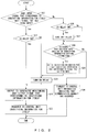
- FIG. 2 is a flowchart illustrating operations of the monitoring unit 10.
- the identifying-information setting unit 14 of the monitoring unit 10 refers to information that is stored in the storage unit 13 and is obtained by associating an input signal, identifying information, and an output signal with one another (hereinafter referred to as identifying-information setting information), acquires an input signal that corresponds to identifying information for itself that has been stored in the storage unit 13, and judges whether or not the acquired input signal and a signal that has been input to the communication unit 15 for itself match with each other (S21).
- the identifying information setting timing is set, for example, at fixed time intervals after initial setting, or when the communication line is connected to a communication connector of the communication unit 15 for itself due to swapping or replacement of the battery module 2.
- the identifying-information setting unit 14 may acquire with reference to the identifying-information setting information identifying information for itself that has been stored in the storage unit 13 and identifying information that corresponds to the signal that has been input to the communication unit 15 for itself, may compare both pieces of identifying information with each other, and may judge whether or not they match with each other.
- the identifying-information setting unit 14 judges that the input signal that corresponds to the identifying information for itself and the signal that has been input to the communication unit 15 match with each other (Yes in S21), when the relay 6 is not turned on (No in S22), the identifying-information setting unit 14 turns on the relay 6 by means of the relay control unit 12 (S23).
- the identifying-information setting unit 14 refers to the indentifying-information setting information, acquires an output signal that corresponds to the identifying information for itself, outputs to the subsequent monitoring unit 10 the acquired output signal (S24), and thereafter transmits to the control unit 3 the identifying information for itself (S25), and terminates the identifying-information setting process.
- the identifying-information setting unit 14 judges that the input signal that corresponds to the identifying information for itself and the signal that has been input to the communication unit 15 do not match with each other (No in S21), when the relay 6 is turned on (Yes in S26), the identifying-information setting unit 14 turns off the relay 6 by means of the relay control unit 12.
- the identifying-information setting unit 14 causes the storage unit 13 to store therein as identifying information for itself identifying information that corresponds to the signal (S29), and thereafter turns on the relay 6 by means of the relay control unit 12 (S23) .
- the identifying-information setting unit 14 refers to the identifying-information setting information, acquires an output signal that corresponds to the identifying information for itself, outputs to the subsequent monitoring unit 10 the acquired output signal (S24), and thereafter transmits to the control unit 3 the identifying information for itself (S25), and terminates the identifying-information setting process.
- the identifying-information setting unit 14 transmits to the control unit 3 information indicating that a communication abnormity has occurred (S30).
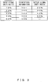
- the battery module 2-1 refers to the identifying-information setting information illustrated in FIG. 3 , acquires identifying information ("101") that corresponds to the "10%”, causes the storage unit 13 to store therein the identifying information ("101") as identifying information for itself, and thereafter turns on the relay 6 by means of the relay control unit 12. Then, the battery module 2-1 refers to the identifying-information setting information illustrated in FIG.
- the battery module 2-2 refers to the identifying-information setting information illustrated in FIG. 3 , acquires duty ratio "30%" of a square wave as an output signal that corresponds to the identifying information ("102") for itself, outputs to the monitoring unit 10 of the subsequent battery module 2-3 the square wave of the acquired duty ratio "30%”, and thereafter transmits to the control unit 3 the identifying information ("102") for itself.
- the battery module 2-3 refers to the identifying-information setting information illustrated in FIG. 3 , acquires identifying information ("103") that corresponds to the duty ratio "30%”, causes the storage unit 13 to store therein the identifying information ("103") as identifying information for itself, and thereafter turns on the relay 6 by means of the relay control unit 12. Then, the battery module 2-3 refers to the identifying-information setting information illustrated in FIG.
- the battery module 2-4 acquires duty ratio "40%" of a square wave as an output signal that corresponds to the identifying information ("103") for itself, outputs to the monitoring unit 10 of the subsequent battery module 2-4 the signal of the acquired duty ratio "40%", and thereafter transmits to the control unit 3 the identifying information ("103") for itself.
- the battery module 2-4 refers to the identifying-information setting information illustrated in FIG.
- the battery module 2-4 refers to the identifying-information setting information illustrated in FIG. 3 , acquires duty ratio "50%" of a square wave as an output signal that corresponds to the identifying information ("104") for itself, outputs to the monitoring unit 10 of the subsequent battery module 2-5 the signal of the acquired duty ratio "50%”, and thereafter transmits to the control unit 3 the identifying information ("104") for itself.
- the battery module 2-5 refers to the identifying-information setting information illustrated in FIG. 3 , acquires identifying information ("105") that corresponds to the duty ratio "50%”, causes the storage unit 13 to store therein the identifying information ("105") as identifying information for itself, and thereafter turns on the relay 6 by means of the relay control unit 12, and transmits to the control unit 3 the identifying information ("105") for itself.
- the configuration of the monitoring unit 10 may be made simpler because it is possible to set identifying information only by transmitting and receiving signals whose duty ratios have been varied.
- the control unit 3 may recognize the number of connected monitoring units 10 by receiving identifying numbers from the monitoring units 10.
- the identifying-information setting unit 14 of the battery module 2 after replacement refers to the identifying-information setting information illustrated in FIG. 3 and acquires "20%” as the duty ratio of a square wave as an input signal that corresponds to "102", which is the identifying information for itself.
- the identifying-information setting unit 14 judges that the acquired duty ratio "20%” and the duty ratio "40%" of a signal that has been input to the communication unit 15 for itselfdo not match with each other, if the relay 6 is not turned off, the identifying-information setting unit 14 turns off the relay 6 by means of the relay control unit 12.
- the identifying-information setting unit 14 refers to the identifying-information setting information illustrated in FIG. 3 , acquires "104" as identifying information that corresponds to the duty ratio "40%" of the signal that has been input to the communication unit 15, causes the storage unit 13 to store therein the acquired identifying information ("104") as identifying information for itself, and thereafter turns on the relay 6 by means of the relay control unit 12.
- the identifying-information setting unit 14 refers to the identifying-information setting information illustrated in FIG. 3 , acquires "50%" as the duty ratio of a square wave as an output signal that corresponds to "104", which is the identifying information for itself, outputs to the monitoring unit 10 of the subsequent battery module 2-5 the square wave of the acquired duty ratio 50%, and thereafter transmits to the control unit 3 "104" as the identifying information for itself, and terminates an identifying-information resetting process.
- the identifying-information setting unit 14 of the subsequent battery module 2-5 might set wrong identifying information according to a signal before a resetting that has been transmitted from the new battery module 2. In such a case, after a resetting of the identifying information for the new battery module 2 has been completed, the identifying information for the subsequent battery module 2-5 is set again.
- the identifying-information setting unit 14 of the battery module 2-4 judges that the input signal of duty ratio "100%” or the input signal of the duty ratio "0%” is not included in the identifying-information setting information illustrated in FIG. 3 and transmits to the control unit 3 information indicating that a communication abnormity has occurred.
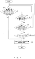
- FIG. 4 is a flowchart illustrating operations of the control unit 3.
- the abnormity determination unit 18 of the control unit 3 receives from at least one battery module 2 among the battery modules 2-1 to 2-5 information indicating that a communication abnormity has occurred (Yes in S41), the abnormity determination unit 18 transitions to the evacuation running mode (S42).
- the abnormity determination unit 18 receives identifying information from the battery modules 2-1 to 2-5 (No in S41 and Yes in S43), if at least one piece of the received identifying information has already been stored in the storage unit 17 (Yes in S44) and the main relay 4 is turned on (Yes in S45), the abnormity determination unit 18 transitions to the evacuation running mode (S42) .
- the mode may transition to the evacuation running mode and thus safety of the vehicle may be enhanced.
- each of the monitoring units 10 of the battery modules 2-1 to 2-5 allocates as identifying information for itself identifying information that corresponds to an input signal that has been input from the preceding control unit 3 or monitoring unit 10, outputs to the subsequent monitoring unit 10 an output signal that differs from the input signal that corresponds to the identifying information that the monitoring unit 10 in question has allocated to itself, and in a case in which identifying information that corresponds to an input signal differs from the identifying information that the monitoring unit 10 in question has allocated to itself, reallocates the identifying information that corresponds to the input signal as identifying information for itself.
- the identifying information may be reset in an easier way in comparison with the case of resetting the identifying information for all the battery modules 2-1 to 2-5 after replacement of the battery module 2-4.
- FIG. 5 is a flowchart illustrating operations of the control unit 3 for confirming the number of battery modules 2. Note that, as described above, it is assumed that when the control unit 3 receives identifying information that has been transmitted from each of the battery modules 2-1 to 2-5, the control unit 3 causes the storage unit 17 to store therein the identifying information.
- control unit 3 sets as the number of battery modules 2 the number of pieces of identifying information that have been stored in the storage unit 17 (S51), and causes the storage unit 17 to store therein the number of battery modules 2 (S52).
- control unit 3 may set as the number of monitoring units 10 the number of pieces of identifying information that have been stored in the storage unit 17.
- control unit 3 may obtain the number of battery modules 2 by obtaining the number of monitoring units 10 and thereafter dividing the number of monitoring units 10 by the number of monitoring units 10 that are provided in each battery module 2. In this case, even when a plurality of monitoring units 10 are provided in one battery module 2, the number of battery modules 2 may be obtained.
- the control unit 3 may grasp the number of battery modules 2 or the number of monitoring units 10.
- it is not necessary to change constants of the program according to the change in the number of battery modules 2 or the number of monitoring units 10 nor is it necessary to prepare another program. Therefore, it is possible to suppress an increase in management cost and an increase in manufacturing cost.
Claims (4)
- Batterieüberwachungsvorrichtung (1), miteiner Vielzahl von Überwachungseinheiten (10), die dazu eingerichtet sind, um Zustände von Batterien zu überwachen, undeiner Steuereinheit (3), die dazu eingerichtet ist, um mit der Vielzahl von Überwachungseinheiten (10) unter Verwendung von Identifizierungsinformation zu kommunizieren, die jeder der Vielzahl von Überwachungseinheiten (10) zugeordnet wurde, die seriell verbunden sind, wobeiwenn ein Signal, das von einer vorhergehenden Steuereinheit (3) oder Überwachungseinheit (10) ausgegeben wurde, zu jeder der Vielzahl von Überwachungseinheiten (10) eingegeben wurde, jede der Überwachungseinheiten (10) dazu eingerichtet ist, um als Identifizierungsinformation für sich selbst Identifizierungsinformation zuzuordnen, die zumindest einem aus einer relativen Einschaltdauer, einer Frequenz, und einer Anzahl von Pulsen pro Einheitszeit des eingegebenen Signals entspricht, und um zu einer nachfolgenden Überwachungseinheit (10) ein Signal auszugeben, dessen relative Einschaltdauer, Frequenz, und/oder Anzahl von Pulsen pro Einheitszeit sich von dem zumindest einen aus der relativen Einschaltdauer, der Frequenz, und der Anzahl von Pulsen pro Einheitszeit des eingegebenen Signals unterscheidet.
- Batterieüberwachungsvorrichtung (1) nach Anspruch 1, wobeijede der Vielzahl von Überwachungseinheiten (10) dazu eingerichtet ist, um die Identifizierungsinformation für sich selbst zu der Steuereinheit (3) zu übertragen, nachdem jede der Überwachungseinheiten (10) die Identifizierungsinformation für sich selbst zugeordnet hat, unddie Steuereinheit (3) dazu eingerichtet ist, um eine Anzahl von Batteriemodulen, die die Überwachungseinheiten (10) enthalten, oder eine Anzahl der Überwachungseinheiten (10) gemäß einer Anzahl von Elementen von Identifizierungsinformation zu erlangen, die empfangen wurden.
- Batterieüberwachungsvorrichtung (1) nach Anspruch 1, wobeijede der Vielzahl von Überwachungseinheiten (10) dazu eingerichtet ist, um in einem Fall, in dem sich Identifizierungsinformation, die dem zumindest einen aus der relativen Einschaltdauer, der Frequenz, und der Anzahl von Pulsen pro Einheitszeit des eingegebenen Signals entspricht, von der Identifizierungsinformation unterscheidet, die die fragliche Überwachungseinheit (10) sich selbst zugeordnet hat, Identifizierungsinformation, die dem zumindest einen aus der relativen Einschaltdauer, der Frequenz, und der Anzahl von Pulsen pro Einheitszeit des eingegebenen Signals entspricht, als Identifizierungsinformation für sich selbst neu zuzuordnen.
- Identifizierungsinformationseinstellverfahren, miteinem Zuordnen, durch Verwenden jeder aus einer Vielzahl von Überwachungseinheiten (10) zur Überwachung von Zuständen von Batterien, von Identifizierungsinformation, die zumindest einem aus einer relativen Einschaltdauer, einer Frequenz, und einer Anzahl von Pulsen pro Einheitszeit eines eingegebenen Signals entspricht, das von einer vorhergehenden Steuereinheit (3) oder Überwachungseinheit (10) eingegeben wurde, die mit der Vielzahl von Überwachungseinheiten kommuniziert, die seriell verbunden sind, als Identifizierungsinformation für sich selbst,einem Ausgeben, durch Verwenden jeder der Überwachungseinheiten (10), eines Signals, dessen relative Einschaltdauer, Frequenz, und/oder Anzahl von Pulsen pro Einheitszeit sich von dem zumindest einen aus der relativen Einschaltdauer, der Frequenz, und der Anzahl von Pulsen pro Einheitszeit des eingegebenen Signals unterscheidet, das der Identifizierungsinformation entspricht, die die fragliche Überwachungseinheit sich selbst zugeordnet hat, zu einer nachfolgenden Überwachungseinheit, undeinem Neuzuordnen, durch Verwenden jeder der Überwachungseinheiten (10), in einem Fall, in dem sich Identifizierungsinformation, die dem zumindest einen aus der relativen Einschaltdauer, der Frequenz, und der Anzahl von Pulsen pro Einheitszeit des eingegebenen Signals entspricht, von der Identifizierungsinformation unterscheidet, die die fragliche Überwachungseinheit sich selbst zugeordnet hat, von Identifizierungsinformation, die dem zumindest einen aus der relativen Einschaltdauer, der Frequenz, und der Anzahl von Pulsen pro Einheitszeit des eingegebenen Signals entspricht, als Identifizierungsinformation für sich selbst.
Applications Claiming Priority (2)
| Application Number | Priority Date | Filing Date | Title |
|---|---|---|---|
| JP2013078427A JP6186813B2 (ja) | 2013-04-04 | 2013-04-04 | 電池監視システム及び識別情報設定方法 |
| PCT/JP2014/052043 WO2014162765A1 (ja) | 2013-04-04 | 2014-01-30 | 電池監視システム及び識別情報設定方法 |
Publications (3)
| Publication Number | Publication Date |
|---|---|
| EP2982999A1 EP2982999A1 (de) | 2016-02-10 |
| EP2982999A4 EP2982999A4 (de) | 2016-09-21 |
| EP2982999B1 true EP2982999B1 (de) | 2018-11-14 |
Family
ID=51658070
Family Applications (1)
| Application Number | Title | Priority Date | Filing Date |
|---|---|---|---|
| EP14779035.6A Active EP2982999B1 (de) | 2013-04-04 | 2014-01-30 | Batterieüberwachungssystem und einstellverfahren für identifizierungsinformation |
Country Status (5)
| Country | Link |
|---|---|
| US (1) | US10001527B2 (de) |
| EP (1) | EP2982999B1 (de) |
| JP (1) | JP6186813B2 (de) |
| CN (1) | CN105074486B (de) |
| WO (1) | WO2014162765A1 (de) |
Cited By (1)
| Publication number | Priority date | Publication date | Assignee | Title |
|---|---|---|---|---|
| DE102020106412A1 (de) | 2020-03-10 | 2021-09-16 | Avl Software And Functions Gmbh | System und Verfahren zur Positionsbestimmung von Batteriemodul/-pack-Steuereinheiten |
Families Citing this family (11)
| Publication number | Priority date | Publication date | Assignee | Title |
|---|---|---|---|---|
| CN106165235B (zh) | 2015-06-30 | 2019-06-04 | 深圳市大疆创新科技有限公司 | 一种电池管理方法、单体电池、飞行控制系统及无人机 |
| CN105429224A (zh) * | 2015-12-16 | 2016-03-23 | 常州格力博有限公司 | 一种支持多个电池包的电气系统 |
| JP6831281B2 (ja) * | 2017-03-27 | 2021-02-17 | 株式会社デンソーテン | 電池監視システムおよび電池監視装置 |
| KR102259970B1 (ko) * | 2017-10-13 | 2021-06-02 | 주식회사 엘지에너지솔루션 | 데이터 입력 스케쥴링 장치 |
| CN110165720B (zh) * | 2018-02-14 | 2020-11-27 | 车王电子股份有限公司 | 电力系统及其管理方法 |
| CN108414926A (zh) * | 2018-03-06 | 2018-08-17 | 苏州正力蔚来新能源科技有限公司 | 用于快换动力电池包的继电器健康状态记录系统 |
| JP7047748B2 (ja) * | 2018-12-19 | 2022-04-05 | 株式会社デンソー | 通信システム |
| CN112054565A (zh) * | 2019-06-06 | 2020-12-08 | 加百裕工业股份有限公司 | 电池管理系统及方法 |
| WO2021019444A1 (en) * | 2019-07-29 | 2021-02-04 | Eco Home As | Method and system for using second life batteries as energy storage in a renewable energy system |
| CN111896874B (zh) * | 2020-07-13 | 2023-05-02 | 江西理工大学 | 基于演化神经网络的电池soc预测方法 |
| JP2022167528A (ja) * | 2021-04-23 | 2022-11-04 | 株式会社デンソー | 通信システム |
Citations (1)
| Publication number | Priority date | Publication date | Assignee | Title |
|---|---|---|---|---|
| US20110080138A1 (en) * | 2009-10-05 | 2011-04-07 | Primearth Ev Energy Co., Ltd. | Battery pack manager |
Family Cites Families (9)
| Publication number | Priority date | Publication date | Assignee | Title |
|---|---|---|---|---|
| JP4054812B2 (ja) * | 2005-03-23 | 2008-03-05 | キヤノン株式会社 | 座標入力方法、情報処理装置、情報処理システムおよび記憶媒体 |
| JP5266702B2 (ja) | 2007-09-28 | 2013-08-21 | 三菱自動車工業株式会社 | 電気自動車の電源管理装置 |
| JP5469813B2 (ja) * | 2008-01-29 | 2014-04-16 | 株式会社日立製作所 | 車両用電池システム |
| JP4796119B2 (ja) * | 2008-12-09 | 2011-10-19 | 三菱重工業株式会社 | 電池装置 |
| JP5208714B2 (ja) * | 2008-12-22 | 2013-06-12 | 株式会社東芝 | 組電池システム |
| KR101156342B1 (ko) * | 2009-08-03 | 2012-06-13 | 삼성에스디아이 주식회사 | 배터리 id 설정 시스템 및 그 구동 방법 |
| JP5785690B2 (ja) * | 2010-03-02 | 2015-09-30 | ラピスセミコンダクタ株式会社 | 組電池システム、電圧監視システム及び監視装置 |
| JP5543014B2 (ja) | 2011-03-14 | 2014-07-09 | 三洋電機株式会社 | 通信システムおよび蓄電池システム |
| JP5693547B2 (ja) * | 2012-11-20 | 2015-04-01 | 三菱重工業株式会社 | 電池管理装置およびその制御方法ならびにプログラム、それを備えた電池監視システム |
-
2013
- 2013-04-04 JP JP2013078427A patent/JP6186813B2/ja not_active Expired - Fee Related
-
2014
- 2014-01-30 CN CN201480017942.9A patent/CN105074486B/zh active Active
- 2014-01-30 EP EP14779035.6A patent/EP2982999B1/de active Active
- 2014-01-30 US US14/780,577 patent/US10001527B2/en active Active
- 2014-01-30 WO PCT/JP2014/052043 patent/WO2014162765A1/ja active Application Filing
Patent Citations (1)
| Publication number | Priority date | Publication date | Assignee | Title |
|---|---|---|---|---|
| US20110080138A1 (en) * | 2009-10-05 | 2011-04-07 | Primearth Ev Energy Co., Ltd. | Battery pack manager |
Cited By (2)
| Publication number | Priority date | Publication date | Assignee | Title |
|---|---|---|---|---|
| DE102020106412A1 (de) | 2020-03-10 | 2021-09-16 | Avl Software And Functions Gmbh | System und Verfahren zur Positionsbestimmung von Batteriemodul/-pack-Steuereinheiten |
| DE102020106412B4 (de) | 2020-03-10 | 2021-12-30 | Avl Software And Functions Gmbh | System und Verfahren zur Positionsbestimmung von Batteriemodul/-pack-Steuereinheiten |
Also Published As
| Publication number | Publication date |
|---|---|
| US20160054393A1 (en) | 2016-02-25 |
| WO2014162765A1 (ja) | 2014-10-09 |
| JP6186813B2 (ja) | 2017-08-30 |
| EP2982999A1 (de) | 2016-02-10 |
| JP2014202581A (ja) | 2014-10-27 |
| CN105074486B (zh) | 2017-08-08 |
| EP2982999A4 (de) | 2016-09-21 |
| CN105074486A (zh) | 2015-11-18 |
| US10001527B2 (en) | 2018-06-19 |
Similar Documents
| Publication | Publication Date | Title |
|---|---|---|
| EP2982999B1 (de) | Batterieüberwachungssystem und einstellverfahren für identifizierungsinformation | |
| JP6831281B2 (ja) | 電池監視システムおよび電池監視装置 | |
| US8587257B2 (en) | Secondary battery device and vehicle | |
| US9647301B2 (en) | Battery monitoring apparatus | |
| US20100052428A1 (en) | Multi-cell battery system, and management number numbering method | |
| CN103250429A (zh) | 用于监控至少一个蓄电池的方法和装置、具有这样的装置的蓄电池以及具有相应的蓄电池的机动车 | |
| US10790553B2 (en) | Wiring diagnostic apparatus, battery system, and power system | |
| US20140320143A1 (en) | Battery management system and method for determining the charge state battery cells, battery and motor vehicle comprising a battery management system | |
| EP2942833A1 (de) | Vorrichtung zur steuerung eines stromspeichersystems | |
| WO2014196280A1 (ja) | 電池監視装置 | |
| KR20140007600A (ko) | 병렬 팩 배터리 시스템의 장애 관리 장치 및 그 방법 | |
| EP3290936B1 (de) | Parallele überwachungsvorrichtung für batteriepackzustand | |
| US20170108555A1 (en) | Battery monitoring device | |
| JP6299378B2 (ja) | 電池監視装置および電池監視方法 | |
| US9804248B2 (en) | Battery monitoring device | |
| JP2018165659A (ja) | 異常検出システムおよび異常検出装置 | |
| US11243257B2 (en) | Control system for a battery system | |
| JP6413314B2 (ja) | 電池監視装置 | |
| JP6172033B2 (ja) | 電池監視装置および電池監視方法 | |
| US20180248230A1 (en) | Battery control apparatus and battery system | |
| JP2015197393A (ja) | 電池監視装置および電池監視方法 | |
| CN106031190B (zh) | 用于管理包括多个单电池的电池组的系统和相应方法 | |
| JP2014106145A (ja) | 電池監視装置 | |
| US20220200297A1 (en) | Battery monitoring system, vehicle, battery monitoring device | |
| JP6477942B2 (ja) | 電池監視装置および電池監視方法 |
Legal Events
| Date | Code | Title | Description |
|---|---|---|---|
| PUAI | Public reference made under article 153(3) epc to a published international application that has entered the european phase |
Free format text: ORIGINAL CODE: 0009012 |
|
| 17P | Request for examination filed |
Effective date: 20150918 |
|
| AK | Designated contracting states |
Kind code of ref document: A1 Designated state(s): AL AT BE BG CH CY CZ DE DK EE ES FI FR GB GR HR HU IE IS IT LI LT LU LV MC MK MT NL NO PL PT RO RS SE SI SK SM TR |
|
| AX | Request for extension of the european patent |
Extension state: BA ME |
|
| DAX | Request for extension of the european patent (deleted) | ||
| RIN1 | Information on inventor provided before grant (corrected) |
Inventor name: YAMAMOTO, SATOSHI Inventor name: HASE, RYUSUKE Inventor name: TSUZUKU, TAKAHIRO Inventor name: YAMAMOTO, TAKUYA Inventor name: KATO, HIROAKI |
|
| A4 | Supplementary search report drawn up and despatched |
Effective date: 20160824 |
|
| RIC1 | Information provided on ipc code assigned before grant |
Ipc: H04L 29/12 20060101ALI20160818BHEP Ipc: H01M 10/48 20060101ALI20160818BHEP Ipc: B60L 3/00 20060101AFI20160818BHEP Ipc: B60L 11/18 20060101ALI20160818BHEP Ipc: G01R 31/36 20060101ALI20160818BHEP Ipc: B60L 3/12 20060101ALI20160818BHEP |
|
| STAA | Information on the status of an ep patent application or granted ep patent |
Free format text: STATUS: EXAMINATION IS IN PROGRESS |
|
| 17Q | First examination report despatched |
Effective date: 20171012 |
|
| REG | Reference to a national code |
Ref country code: DE Ref legal event code: R079 Ref document number: 602014036083 Country of ref document: DE Free format text: PREVIOUS MAIN CLASS: G01R0031360000 Ipc: B60L0003000000 |
|
| GRAP | Despatch of communication of intention to grant a patent |
Free format text: ORIGINAL CODE: EPIDOSNIGR1 |
|
| STAA | Information on the status of an ep patent application or granted ep patent |
Free format text: STATUS: GRANT OF PATENT IS INTENDED |
|
| RIC1 | Information provided on ipc code assigned before grant |
Ipc: B60L 11/18 20060101ALI20180424BHEP Ipc: B60L 3/00 20060101AFI20180424BHEP Ipc: H04L 29/12 20060101ALI20180424BHEP Ipc: G01R 31/36 20060101ALI20180424BHEP Ipc: H01M 10/48 20060101ALI20180424BHEP Ipc: B60L 3/12 20060101ALI20180424BHEP |
|
| INTG | Intention to grant announced |
Effective date: 20180514 |
|
| RIN1 | Information on inventor provided before grant (corrected) |
Inventor name: HASE, RYUSUKE Inventor name: YAMAMOTO, TAKUYA Inventor name: KATO, HIROAKI Inventor name: TSUZUKU, TAKAHIRO Inventor name: YAMAMOTO, SATOSHI |
|
| GRAS | Grant fee paid |
Free format text: ORIGINAL CODE: EPIDOSNIGR3 |
|
| GRAA | (expected) grant |
Free format text: ORIGINAL CODE: 0009210 |
|
| STAA | Information on the status of an ep patent application or granted ep patent |
Free format text: STATUS: THE PATENT HAS BEEN GRANTED |
|
| AK | Designated contracting states |
Kind code of ref document: B1 Designated state(s): AL AT BE BG CH CY CZ DE DK EE ES FI FR GB GR HR HU IE IS IT LI LT LU LV MC MK MT NL NO PL PT RO RS SE SI SK SM TR |
|
| REG | Reference to a national code |
Ref country code: CH Ref legal event code: EP Ref country code: AT Ref legal event code: REF Ref document number: 1064388 Country of ref document: AT Kind code of ref document: T Effective date: 20181115 |
|
| REG | Reference to a national code |
Ref country code: DE Ref legal event code: R096 Ref document number: 602014036083 Country of ref document: DE |
|
| REG | Reference to a national code |
Ref country code: IE Ref legal event code: FG4D |
|
| REG | Reference to a national code |
Ref country code: NL Ref legal event code: MP Effective date: 20181114 |
|
| REG | Reference to a national code |
Ref country code: LT Ref legal event code: MG4D |
|
| REG | Reference to a national code |
Ref country code: AT Ref legal event code: MK05 Ref document number: 1064388 Country of ref document: AT Kind code of ref document: T Effective date: 20181114 |
|
| PG25 | Lapsed in a contracting state [announced via postgrant information from national office to epo] |
Ref country code: ES Free format text: LAPSE BECAUSE OF FAILURE TO SUBMIT A TRANSLATION OF THE DESCRIPTION OR TO PAY THE FEE WITHIN THE PRESCRIBED TIME-LIMIT Effective date: 20181114 Ref country code: AT Free format text: LAPSE BECAUSE OF FAILURE TO SUBMIT A TRANSLATION OF THE DESCRIPTION OR TO PAY THE FEE WITHIN THE PRESCRIBED TIME-LIMIT Effective date: 20181114 Ref country code: NO Free format text: LAPSE BECAUSE OF FAILURE TO SUBMIT A TRANSLATION OF THE DESCRIPTION OR TO PAY THE FEE WITHIN THE PRESCRIBED TIME-LIMIT Effective date: 20190214 Ref country code: FI Free format text: LAPSE BECAUSE OF FAILURE TO SUBMIT A TRANSLATION OF THE DESCRIPTION OR TO PAY THE FEE WITHIN THE PRESCRIBED TIME-LIMIT Effective date: 20181114 Ref country code: IS Free format text: LAPSE BECAUSE OF FAILURE TO SUBMIT A TRANSLATION OF THE DESCRIPTION OR TO PAY THE FEE WITHIN THE PRESCRIBED TIME-LIMIT Effective date: 20190314 Ref country code: LT Free format text: LAPSE BECAUSE OF FAILURE TO SUBMIT A TRANSLATION OF THE DESCRIPTION OR TO PAY THE FEE WITHIN THE PRESCRIBED TIME-LIMIT Effective date: 20181114 Ref country code: BG Free format text: LAPSE BECAUSE OF FAILURE TO SUBMIT A TRANSLATION OF THE DESCRIPTION OR TO PAY THE FEE WITHIN THE PRESCRIBED TIME-LIMIT Effective date: 20190214 Ref country code: HR Free format text: LAPSE BECAUSE OF FAILURE TO SUBMIT A TRANSLATION OF THE DESCRIPTION OR TO PAY THE FEE WITHIN THE PRESCRIBED TIME-LIMIT Effective date: 20181114 Ref country code: LV Free format text: LAPSE BECAUSE OF FAILURE TO SUBMIT A TRANSLATION OF THE DESCRIPTION OR TO PAY THE FEE WITHIN THE PRESCRIBED TIME-LIMIT Effective date: 20181114 |
|
| PG25 | Lapsed in a contracting state [announced via postgrant information from national office to epo] |
Ref country code: NL Free format text: LAPSE BECAUSE OF FAILURE TO SUBMIT A TRANSLATION OF THE DESCRIPTION OR TO PAY THE FEE WITHIN THE PRESCRIBED TIME-LIMIT Effective date: 20181114 Ref country code: RS Free format text: LAPSE BECAUSE OF FAILURE TO SUBMIT A TRANSLATION OF THE DESCRIPTION OR TO PAY THE FEE WITHIN THE PRESCRIBED TIME-LIMIT Effective date: 20181114 Ref country code: AL Free format text: LAPSE BECAUSE OF FAILURE TO SUBMIT A TRANSLATION OF THE DESCRIPTION OR TO PAY THE FEE WITHIN THE PRESCRIBED TIME-LIMIT Effective date: 20181114 Ref country code: SE Free format text: LAPSE BECAUSE OF FAILURE TO SUBMIT A TRANSLATION OF THE DESCRIPTION OR TO PAY THE FEE WITHIN THE PRESCRIBED TIME-LIMIT Effective date: 20181114 Ref country code: GR Free format text: LAPSE BECAUSE OF FAILURE TO SUBMIT A TRANSLATION OF THE DESCRIPTION OR TO PAY THE FEE WITHIN THE PRESCRIBED TIME-LIMIT Effective date: 20190215 Ref country code: PT Free format text: LAPSE BECAUSE OF FAILURE TO SUBMIT A TRANSLATION OF THE DESCRIPTION OR TO PAY THE FEE WITHIN THE PRESCRIBED TIME-LIMIT Effective date: 20190314 |
|
| PG25 | Lapsed in a contracting state [announced via postgrant information from national office to epo] |
Ref country code: DK Free format text: LAPSE BECAUSE OF FAILURE TO SUBMIT A TRANSLATION OF THE DESCRIPTION OR TO PAY THE FEE WITHIN THE PRESCRIBED TIME-LIMIT Effective date: 20181114 Ref country code: PL Free format text: LAPSE BECAUSE OF FAILURE TO SUBMIT A TRANSLATION OF THE DESCRIPTION OR TO PAY THE FEE WITHIN THE PRESCRIBED TIME-LIMIT Effective date: 20181114 Ref country code: IT Free format text: LAPSE BECAUSE OF FAILURE TO SUBMIT A TRANSLATION OF THE DESCRIPTION OR TO PAY THE FEE WITHIN THE PRESCRIBED TIME-LIMIT Effective date: 20181114 Ref country code: CZ Free format text: LAPSE BECAUSE OF FAILURE TO SUBMIT A TRANSLATION OF THE DESCRIPTION OR TO PAY THE FEE WITHIN THE PRESCRIBED TIME-LIMIT Effective date: 20181114 |
|
| REG | Reference to a national code |
Ref country code: DE Ref legal event code: R097 Ref document number: 602014036083 Country of ref document: DE |
|
| PG25 | Lapsed in a contracting state [announced via postgrant information from national office to epo] |
Ref country code: SK Free format text: LAPSE BECAUSE OF FAILURE TO SUBMIT A TRANSLATION OF THE DESCRIPTION OR TO PAY THE FEE WITHIN THE PRESCRIBED TIME-LIMIT Effective date: 20181114 Ref country code: EE Free format text: LAPSE BECAUSE OF FAILURE TO SUBMIT A TRANSLATION OF THE DESCRIPTION OR TO PAY THE FEE WITHIN THE PRESCRIBED TIME-LIMIT Effective date: 20181114 Ref country code: SM Free format text: LAPSE BECAUSE OF FAILURE TO SUBMIT A TRANSLATION OF THE DESCRIPTION OR TO PAY THE FEE WITHIN THE PRESCRIBED TIME-LIMIT Effective date: 20181114 Ref country code: RO Free format text: LAPSE BECAUSE OF FAILURE TO SUBMIT A TRANSLATION OF THE DESCRIPTION OR TO PAY THE FEE WITHIN THE PRESCRIBED TIME-LIMIT Effective date: 20181114 Ref country code: MC Free format text: LAPSE BECAUSE OF FAILURE TO SUBMIT A TRANSLATION OF THE DESCRIPTION OR TO PAY THE FEE WITHIN THE PRESCRIBED TIME-LIMIT Effective date: 20181114 |
|
| REG | Reference to a national code |
Ref country code: CH Ref legal event code: PL |
|
| PLBE | No opposition filed within time limit |
Free format text: ORIGINAL CODE: 0009261 |
|
| STAA | Information on the status of an ep patent application or granted ep patent |
Free format text: STATUS: NO OPPOSITION FILED WITHIN TIME LIMIT |
|
| PG25 | Lapsed in a contracting state [announced via postgrant information from national office to epo] |
Ref country code: LU Free format text: LAPSE BECAUSE OF NON-PAYMENT OF DUE FEES Effective date: 20190130 |
|
| REG | Reference to a national code |
Ref country code: BE Ref legal event code: MM Effective date: 20190131 |
|
| 26N | No opposition filed |
Effective date: 20190815 |
|
| GBPC | Gb: european patent ceased through non-payment of renewal fee |
Effective date: 20190214 |
|
| REG | Reference to a national code |
Ref country code: IE Ref legal event code: MM4A |
|
| PG25 | Lapsed in a contracting state [announced via postgrant information from national office to epo] |
Ref country code: FR Free format text: LAPSE BECAUSE OF NON-PAYMENT OF DUE FEES Effective date: 20190131 Ref country code: SI Free format text: LAPSE BECAUSE OF FAILURE TO SUBMIT A TRANSLATION OF THE DESCRIPTION OR TO PAY THE FEE WITHIN THE PRESCRIBED TIME-LIMIT Effective date: 20181114 |
|
| PG25 | Lapsed in a contracting state [announced via postgrant information from national office to epo] |
Ref country code: BE Free format text: LAPSE BECAUSE OF NON-PAYMENT OF DUE FEES Effective date: 20190131 |
|
| PG25 | Lapsed in a contracting state [announced via postgrant information from national office to epo] |
Ref country code: LI Free format text: LAPSE BECAUSE OF NON-PAYMENT OF DUE FEES Effective date: 20190131 Ref country code: CH Free format text: LAPSE BECAUSE OF NON-PAYMENT OF DUE FEES Effective date: 20190131 |
|
| PG25 | Lapsed in a contracting state [announced via postgrant information from national office to epo] |
Ref country code: IE Free format text: LAPSE BECAUSE OF NON-PAYMENT OF DUE FEES Effective date: 20190130 Ref country code: GB Free format text: LAPSE BECAUSE OF NON-PAYMENT OF DUE FEES Effective date: 20190214 |
|
| PG25 | Lapsed in a contracting state [announced via postgrant information from national office to epo] |
Ref country code: TR Free format text: LAPSE BECAUSE OF FAILURE TO SUBMIT A TRANSLATION OF THE DESCRIPTION OR TO PAY THE FEE WITHIN THE PRESCRIBED TIME-LIMIT Effective date: 20181114 |
|
| PG25 | Lapsed in a contracting state [announced via postgrant information from national office to epo] |
Ref country code: MT Free format text: LAPSE BECAUSE OF NON-PAYMENT OF DUE FEES Effective date: 20190130 |
|
| PG25 | Lapsed in a contracting state [announced via postgrant information from national office to epo] |
Ref country code: CY Free format text: LAPSE BECAUSE OF FAILURE TO SUBMIT A TRANSLATION OF THE DESCRIPTION OR TO PAY THE FEE WITHIN THE PRESCRIBED TIME-LIMIT Effective date: 20181114 |
|
| PG25 | Lapsed in a contracting state [announced via postgrant information from national office to epo] |
Ref country code: HU Free format text: LAPSE BECAUSE OF FAILURE TO SUBMIT A TRANSLATION OF THE DESCRIPTION OR TO PAY THE FEE WITHIN THE PRESCRIBED TIME-LIMIT; INVALID AB INITIO Effective date: 20140130 |
|
| PG25 | Lapsed in a contracting state [announced via postgrant information from national office to epo] |
Ref country code: MK Free format text: LAPSE BECAUSE OF FAILURE TO SUBMIT A TRANSLATION OF THE DESCRIPTION OR TO PAY THE FEE WITHIN THE PRESCRIBED TIME-LIMIT Effective date: 20181114 |
|
| PGFP | Annual fee paid to national office [announced via postgrant information from national office to epo] |
Ref country code: DE Payment date: 20221207 Year of fee payment: 10 |