EP2982531A1 - Eckausbildung einer hohlkammerdichtung - Google Patents
Eckausbildung einer hohlkammerdichtung Download PDFInfo
- Publication number
- EP2982531A1 EP2982531A1 EP15002230.9A EP15002230A EP2982531A1 EP 2982531 A1 EP2982531 A1 EP 2982531A1 EP 15002230 A EP15002230 A EP 15002230A EP 2982531 A1 EP2982531 A1 EP 2982531A1
- Authority
- EP
- European Patent Office
- Prior art keywords
- hollow chamber
- chamber seal
- corner
- filler
- component
- Prior art date
- Legal status (The legal status is an assumption and is not a legal conclusion. Google has not performed a legal analysis and makes no representation as to the accuracy of the status listed.)
- Granted
Links
- 239000000945 filler Substances 0.000 claims abstract description 22
- 230000008093 supporting effect Effects 0.000 claims abstract description 8
- 239000013536 elastomeric material Substances 0.000 claims abstract description 5
- 230000007704 transition Effects 0.000 claims description 3
- 230000015572 biosynthetic process Effects 0.000 claims 2
- 238000010276 construction Methods 0.000 claims 1
- 238000001746 injection moulding Methods 0.000 claims 1
- 230000002035 prolonged effect Effects 0.000 abstract description 3
- 238000004519 manufacturing process Methods 0.000 abstract description 2
- 238000007789 sealing Methods 0.000 description 9
- 239000000243 solution Substances 0.000 description 3
- 229920001971 elastomer Polymers 0.000 description 2
- 238000002347 injection Methods 0.000 description 2
- 239000007924 injection Substances 0.000 description 2
- 238000009434 installation Methods 0.000 description 2
- 230000000295 complement effect Effects 0.000 description 1
- 230000006835 compression Effects 0.000 description 1
- 238000007906 compression Methods 0.000 description 1
- 230000001419 dependent effect Effects 0.000 description 1
- 239000000806 elastomer Substances 0.000 description 1
- 230000037431 insertion Effects 0.000 description 1
- 238000003780 insertion Methods 0.000 description 1
- 210000001503 joint Anatomy 0.000 description 1
- 239000000463 material Substances 0.000 description 1
- 230000000717 retained effect Effects 0.000 description 1
Images

Classifications
-
- B—PERFORMING OPERATIONS; TRANSPORTING
- B60—VEHICLES IN GENERAL
- B60J—WINDOWS, WINDSCREENS, NON-FIXED ROOFS, DOORS, OR SIMILAR DEVICES FOR VEHICLES; REMOVABLE EXTERNAL PROTECTIVE COVERINGS SPECIALLY ADAPTED FOR VEHICLES
- B60J10/00—Sealing arrangements
- B60J10/20—Sealing arrangements characterised by the shape
- B60J10/21—Sealing arrangements characterised by the shape having corner parts or bends
-
- B—PERFORMING OPERATIONS; TRANSPORTING
- B60—VEHICLES IN GENERAL
- B60J—WINDOWS, WINDSCREENS, NON-FIXED ROOFS, DOORS, OR SIMILAR DEVICES FOR VEHICLES; REMOVABLE EXTERNAL PROTECTIVE COVERINGS SPECIALLY ADAPTED FOR VEHICLES
- B60J10/00—Sealing arrangements
- B60J10/20—Sealing arrangements characterised by the shape
- B60J10/24—Sealing arrangements characterised by the shape having tubular parts
-
- B—PERFORMING OPERATIONS; TRANSPORTING
- B60—VEHICLES IN GENERAL
- B60J—WINDOWS, WINDSCREENS, NON-FIXED ROOFS, DOORS, OR SIMILAR DEVICES FOR VEHICLES; REMOVABLE EXTERNAL PROTECTIVE COVERINGS SPECIALLY ADAPTED FOR VEHICLES
- B60J10/00—Sealing arrangements
- B60J10/30—Sealing arrangements characterised by the fastening means
-
- B—PERFORMING OPERATIONS; TRANSPORTING
- B60—VEHICLES IN GENERAL
- B60J—WINDOWS, WINDSCREENS, NON-FIXED ROOFS, DOORS, OR SIMILAR DEVICES FOR VEHICLES; REMOVABLE EXTERNAL PROTECTIVE COVERINGS SPECIALLY ADAPTED FOR VEHICLES
- B60J10/00—Sealing arrangements
- B60J10/80—Sealing arrangements specially adapted for opening panels, e.g. doors
- B60J10/82—Sealing arrangements specially adapted for opening panels, e.g. doors for movable panels in roofs
-
- B—PERFORMING OPERATIONS; TRANSPORTING
- B60—VEHICLES IN GENERAL
- B60J—WINDOWS, WINDSCREENS, NON-FIXED ROOFS, DOORS, OR SIMILAR DEVICES FOR VEHICLES; REMOVABLE EXTERNAL PROTECTIVE COVERINGS SPECIALLY ADAPTED FOR VEHICLES
- B60J10/00—Sealing arrangements
- B60J10/90—Sealing arrangements specially adapted for non-fixed roofs, e.g. foldable roofs or removable hard-tops
Definitions
- the present invention relates to a Eck put a hollow chamber seal according to the preamble of claim 1.
- the corner area of a hollow chamber seal is a problem zone, because the hollow chamber seal deforms during assembly in this area, changing its cross section. This has functional and aesthetic disadvantages, but can be avoided by appropriate measures.
- a hollow profile seal preferably described for the feed opening of a baking oven or cooker, which is peripherally attached to the edge of the feed opening, wherein in the corner or curvature sections stiffening elements are mounted in the hollow profile, and the circumferential of the end portions of the feed opening around the hollow profile Seal formed joint is selected so that a stiffening element bridges the joint and connects the adjacent end portions.
- the hollow chamber serves to receive a sensor device and the task is to be solved, a function of the sensor device in the range of corner curves To allow the smallest possible radius of curvature.
- the hollow profile is recessed in the corner to the hollow chamber and the recessed cutout filled by a separately manufactured corner unit, which is tuned to the angle of curvature of the corner. This ensures that stresses which are caused by the curvature of the elastic hollow profile, are reduced, and also in the region of the corner curvature of the cross section of the hollow chamber with respect to the rectilinear regions remains the same.
- a generic Eck term is from the DE 299 23 157 U1 known.
- This is a mounted on a vehicle sunroof hollow chamber seal.
- the sunroof must be sealed against the vehicle roof in the closed state.
- a multi-part hollow chamber seal is attached to the edge of the sunroof.
- This hollow chamber seal is composed of a bent around a corner extending seal member and a connected via a butt joint on this subsequent seal member.
- a connecting seam passing through the seam is used, which extends over the entire bend of the sealing part extending around the corner.
- This connecting hose takes as a filler the forces acting during assembly in the corner region of the hollow chamber seal deformation forces and directs them into the sunroof.
- the original cross-section of the hollow chamber seal in the corner region is substantially retained, whereby wind noise is avoided and a reliable sealing function is ensured even in this area.
- a disadvantage of this known from the prior art solution is that the above advantages are often no longer present after prolonged use, since the connecting tube migrates in the hollow chamber seal and thereby its supporting effect is repealed. Furthermore, the introduction of the connecting tube in the hollow chamber seal is very expensive. Another disadvantage is the fact that at the junction between the two sealing parts an aesthetics disturbing butt seam is visible.
- Object of the present invention is to provide a corner education generic type available that reliably prevents deformation of a hollow chamber seal, even after prolonged use, is easy to manufacture, and also satisfies aesthetic concerns.
- the hardness ratio between the elastomeric material of the heads and the elastomeric material of the hollow chamber seal are coordinated so that the heads deform sufficiently, but still exert a supporting force on the hollow chamber seal, so that it substantially maintains its cross section in the corner ,
- the solution according to the invention is also inexpensive, since only small tooling costs incurred.
- the patches are inexpensive to produce as injection molded parts. Due to the supporting effect of Putties in the corner area where the sealing function of the hollow chamber seal remains fully preserved there. Furthermore, the seal also has a mechanical hold transversely to the mounting plane of the hollow chamber seal.
- the solution according to the invention also meets aesthetic requirements, since it provides a uniform, continuous appearance.
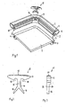
- Fig. 1 shows a panel 1, which may be, for example, a car sliding roof.
- a hollow chamber seal 2 is to be attached, the panel 1 against another component, for. B. a car roof, to seal.
- the panel 1 is encapsulated with a plastic frame 3, which is provided with a circumferential receiving groove. 4 is provided.
- the receiving groove 4 has in its entrance area two opposing undercuts. 5
- the hollow chamber seal 2 is made of an elastomer, for. As rubber. It has a continuous over its entire length cavity 6. From the mounting side of the interior of the cavity 6 projects a sealing lip 7 down, which is provided on its inside with a vertically projecting connector 8.
- the header 8 has at its transition to the sealing lip 7 two opposing undercuts 9, which are complementary to the undercuts 5 of the receiving groove 4 are formed. Furthermore, the connector strip 8 is equipped with a continuous over its entire length cavity 10.
- the header 8 is inserted into the receiving groove 4 of the panel 1.
- the undercuts 5 of the plastic frame 3 and the undercuts 9 of the connector strip 8 cooperate so that the hollow chamber seal 2 can be easily inserted into the receiving groove 4 and is held firmly in this position on the panel 1.
- the cavity 10 causes a temporary compression of the connector 8, which facilitates the insertion of the connector 8 in the receiving groove 4.
- the hollow chamber seal 2 in the corner 11 would change greatly in cross section, so that the sealing function would deteriorate in this area or even no longer exist.
- a filler 12 is provided in the corner region 11 of the hollow chamber seal 2.
- the filler 12 is made as an injection molded part with a head 13 and a foot 14.
- the head 13 is made made of an elastomeric material, while the foot 14 is made of a rigid plastic material.
- the foot 14 has at its free end two legs 16, which include a right angle between them.
- the legs 16 is followed by a shaft 15, which merges into the T-shaped head 13, which has a shoulder 17 at its top for abutment with the inner wall of the hollow chamber seal 2.
- free cuts 18 are provided, which serve to allow a zwteilungsbind deformation of the head 13 during assembly.
- the foot 14 of the filler 12 is not as wide as the head 13, as best of Fig. 3 evident. This difference in width is required, on the one hand, to provide a sufficiently wide shoulder 16 and, on the other hand, to ensure that the foot 14 can be inserted during assembly into the receiving groove 4 of the frame 3.
- the header 8 is cut away in this area. Furthermore, a slot 19 is introduced to the inside of the hollow chamber seal 2 in order to provide access into the cavity 6 of the hollow chamber seal 2.
- the filler 12 is inserted through the slot 19 prior to assembly of the hollow chamber seal 2 on the panel 1, so that the head 12 is arranged in the cavity 6, while the foot 14 protrudes on the inside of the hollow chamber seal 2.
- the shoulder 16 of the head 13 is under appropriate deformation of the head 13 against the inner wall of the hollow chamber seal 2 and supports it.
- the support force is derived via the foot 14 to the frame 3, wherein the legs 17 of the foot 14 rest on both sides of the corner of the frame 3.
- Fig. 4 the assembled state of the filler 12 is shown.
Landscapes
- Engineering & Computer Science (AREA)
- Mechanical Engineering (AREA)
- Seal Device For Vehicle (AREA)
- Building Environments (AREA)
- Gasket Seals (AREA)
Abstract
Description
- Die vorliegende Erfindung betrifft eine Eckausbildung einer Hohlkammerdichtung gemäß dem Oberbegriff des Anspruchs 1.
- Der Eckbereich einer Hohlkammerdichtung ist eine Problemzone, da sich die Hohlkammerdichtung bei der Montage in diesem Bereich unter Veränderung Ihres Querschnitts deformiert. Dies hat funktionelle und ästhetische Nachteile, die aber durch geeignete Maßnahmen vermieden werden können.
- In der
DE 10 2004 020 799 A1 wird eine Hohlprofildichtung, vorzugsweise für die Beschickungsöffnung eines Backofens oder Herdes beschrieben, die umlaufend am Rand der Beschickungsöffnung befestigt wird, wobei In den Eck- oder Krümmungs-abschnitten Versteifungselemente In dem Hohlprofil angebracht werden, und die von den Endabschnitten der um die Beschickungsöffnung umlaufenden Hohlprofil-dichtung gebildete Stoßstelle so gewählt wird, dass ein Versteifungselement die Stoßstelle überbrückt und die benachbarten Endabschnitte verbindet. - Aus der
DE 100 46 975 A1 ist ein elastisches Hohlprofil mit wenigstens einer Hohlkammer und wenigstens einer Eckkrümmung zur bündigen Verlegung entlang eines Eckbereiches eines Fahrzeugausschnittes für ein bewegliches Schließteil bekannt, wobei die Hohlkammer zur Aufnahme einer Sensoreinrichtung dient und die Aufgabe gelöst werden soll, eine Funktion der Sensoreinrichtung im Bereich von Eckkrümmungen mit möglichst kleinem Krümmungsradius zu ermöglichen. Zu diesem Zweck wird das Hohlprofil im Eckbereich bis zur Hohlkammer hin ausgespart und der ausgesparte Ausschnitt durch eine separat hergestellte Eckeinheit ausgefüllt, die auf den Krümmungswinkel des Eckbereichs abgestimmt ist. Hierdurch wird erreicht, dass Spannungen, die durch die Krümmung des elastischen Hohlprofils verursacht werden, herabgesetzt werden, und auch im Bereich der Eckkrümmung der Querschnitt der Hohlkammer gegenüber den geradlinigen Bereichen gleich bleibt. - Eine gattungsgemäße Eckausbildung ist aus der
DE 299 23 157 U1 bekannt. Es handelt sich hier um eine an einem Fahrzeug-Schiebedach angebrachte Hohlkammerdichtung. Das Schiebedach muss gegenüber dem Fahrzeugdach im geschlossenen Zustand abgedichtet sein. Dazu ist am Rand des Schiebedachs eine mehrteilige Hohlkammerdichtung befestigt. Diese Hohlkammerdichtung setzt sich aus einem um eine Ecke gebogen verlaufenden Dichtungsteil und einem sich über eine Stoßnaht an dieses anschließenden weiteren Dichtungsteil zusammen. In diese beiden Dichtungsteile ist ein die Stoßnaht durchsetzender Verbindungsschlauch eingesetzt, der sich über die gesamte Biegung des um die Ecke verlaufenden Dichtungsteils erstreckt. Dieser Verbindungsschlauch nimmt als Füllstück die bei der Montage im Eckbereich der Hohlkammerdichtung wirkenden Deformationskräfte auf und leitet sie In das Schiebedach ab. Dadurch bleibt der ursprüngliche Querschnitt der Hohlkammerdichtung im Eckbereich im Wesentlichen erhalten, wodurch Windgeräusche vermieden werden und eine zuverlässige Dichtungsfunktion auch in diesem Bereich sichergestellt ist. - Nachteilig an dieser aus dem Stand der Technik bekannten Lösung ist dass die oben genannten Vorteile nach längerem Gebrauch häufig nicht mehr vorhanden sind, da der Verbindungsschlauch in der Hohlkammerdichtung wandert und dadurch seine Stützwirkung aufgehoben ist. Des Weiteren ist das Einbringen des Verbindungsschlauches in die Hohlkammerdichtung sehr aufwändig. Ein weiterer Nachteil ist darin zu sehen, dass an der Verbindungsstelle zwischen den beiden Dichtungsteilen eine die Ästhetik störende Stoßnaht sichtbar ist.
- Aufgabe der vorliegenden Erfindung ist es, eine Eckausbildung gattungsgemäßer Art zur Verfügung zu stellen, die eine Deformation einer Hohlkammerdichtung auch nach längerem Gebrauch zuverlässig verhindert, einfach herzustellen ist, und auch ästhetische Belange erfüllt.
- Diese Aufgabe wird erfindungsgemäß mit einer Eckausbildung gelöst, die die Merkmale des Anspruchs 1 aufweist.
- Die Montage einer erfindungsgemäßen Eckausbildung gestaltet sich sehr einfach. Dazu werden in eine für den Einsatzfall abgelängte Hohlkammerdichtung in den Bereichen, in denen nach der Montage die Ecken ausgebildet sind, Schlitze in die Hohlkammerdichtung eingebracht, durch die hindurch die Köpfe der Füllstücke in die Hohlkammerdichtung eingesteckt werden. Die derart vormontierten Hohlkammerdichtungsabschnitte brauchen dann am Einsatzort nur noch um das abzudichtende Bauteil herumgelegt zu werden, wobei die Füllstücke in den Eckbereichen angeordnet sind. Beim Montieren der Hohlkammerdichtung deformieren sich die Köpfe der Füllstücke und stützen gleichzeitig die Wandung der Hohlkammerdichtung ab, wobei die Stützkräfte über den Fuß der Füllstücke in das Bauteil abgeleitet werden. Es versteht sich, dass das Härteverhältnis zwischen den elastomeren Material der Köpfe und dem elastomeren Material der Hohlkammerdichtung so aufeinander abgestimmt sind, dass sich die Köpfe ausreichend deformieren, aber dennoch eine Stützkraft auf die Hohlkammerdichtung ausüben, so dass diese im Eckbereich ihren Querschnitt im Wesentlichen beibehält.
- Neben einer einfachen Montage ist die erfindungsgemäße Lösung auch kostengünstig, da nur geringe Werkzeugkosten anfallen. Die Füllstücke sind kostengünstig als Spritzgussteile herstellbar. Durch die Stützwirkung der Füllstücke im Eckbereich bleibt dort die Dichtfunktion der Hohlkammerdichtung im vollen Maße erhalten. Des Weiteren hat die Dichtung auch quer zur Montageebene der Hohlkammerdichtung einen mechanischen Halt. Die erfindungsgemäße Lösung erfüllt auch ästhetische Anforderungen, da sie eine gleichmäßige, durchgängige Optik bietet.
- Weitere vorteilhafte Ausgestaltungen der Erfindung ergeben sich aus den Unteransprüchen.
- Die Erfindung wird nachstehend anhand von Ausführungsbeispielen näher erläutert. In der dazugehörigen Zeichnung zeigt:
- Fig. 1
- einen perspektivischen Blick auf ein Bauteil, eine daran anzubringende Hohlkammerdichtung und ein Füllstück vor der Montage,
- Fig. 2
- eine Vorderansicht des Füllstückes gemäß
Fig. 1 im vergrößerten Maßstab, - Fig. 3
- eine Seitenansicht des Füllstückes, und
- Fig. 4
- eine Darstellung gemäß
Fig. 1 bei montierter Hohlkammerdichtung, wobei die Hohlkammerdichtung transparent dargestellt ist. -
Fig. 1 zeigt ein Paneel 1, bei dem es sich beispielsweise um ein Autoschiebedach handeln kann. An den Randbereich des Paneels 1 soll eine Hohlkammerdichtung 2 angebracht werden, die das Paneel 1 gegen ein anderes Bauteil, z. B. ein Autodach, abdichten soll. Das Paneel 1 ist mit einem Kunststoffrahmen 3 umspritzt, der mit einer umlaufenden Aufnahmenut 4 versehen ist. Die Aufnahmenut 4 besitzt in ihrem Eingangsbereich zwei sich gegenüberliegende Hinterschneidungen 5. - Die Hohlkammerdichtung 2 ist aus einem Elastomer, z. B. Gummi, gefertigt. Sie besitzt einen über ihre gesamte Länge durchgehenden Hohlraum 6. Von der montageseitigen Innenseite des Hohlraums 6 ragt eine Dichtlippe 7 nach unten, die auf ihrer Innenseite mit einer senkrecht abragenden Steckleiste 8 versehen ist. Die Steckleiste 8 weist an ihrem Übergang zur Dichtlippe 7 zwei sich gegenüberliegende Hinterschneidungen 9 auf, die komplementär zu den Hinterschneidungen 5 der Aufnahmenut 4 ausgebildet sind. Des Weiteren ist die Steckleiste 8 mit einem über ihre gesamte Länge durchlaufenden Hohlraum 10 ausgestattet.
- Zur Montage der Hohlkammerdichtung 2 am Paneel 1 wird die Steckleiste 8 in die Aufnahmenut 4 des Paneel 1 eingesteckt. Dabei wirken die Hinterschneidungen 5 des Kunststoffrahmens 3 und die Hinterschneidungen 9 der Steckleiste 8 so zusammen, dass die Hohlkammerdichtung 2 problemlos in die Aufnahmenut 4 eingesteckt werden kann und in dieser Position fest am Paneel 1 gehalten wird. Beim Einstecken der Steckleiste 8 in die Aufnahmenut 4 bewirkt der Hohlraum 10 eine vorübergehende Komprimierung der Steckleiste 8, die das Einstecken der Steckleiste 8 in die Aufnahmenut 4 erleichtert.
- Ohne weitere Vorkehrungen würde sich die Hohlkammerdichtung 2 im Eckbereich 11 stark im Querschnitt ändern, so dass sich die Dichtfunktion in diesem Bereich verschlechtern würde oder sogar nicht mehr vorhanden wäre.
- Zur Vermeidung dieser Nachteile ist im Eckbereich 11 der Hohlkammerdichtung 2 ein Füllstück 12 vorgesehen. Das Füllstück 12 ist als Spritzgussteil mit einem Kopf 13 und einem Fuß 14 hergestellt. Der Kopf 13 besteht aus einem elastomeren Material, während der Fuß 14 aus einem biegesteifen Kunststoffmaterial besteht. Der Fuß 14 besitzt an seinem freien Ende zwei Schenkel 16, die zwischen sich einen rechten Winkel einschließen. Den Schenkeln 16 schließt sich ein Schaft 15 an, der in den T-förmig gestalteten Kopf 13 übergeht, der an seiner Oberseite eine Schulter 17 zur Anlage an die Innenwandung der Hohlkammerdichtung 2 aufweist. Am Übergang des Schaftes 15 zum Kopf 13 sind Freischnitte 18 vorgesehen, die dazu dienen, bei der Montage eine zwängungsfreie Verformung des Kopfes 13 zu ermöglichen. Der Fuß 14 des Füllstückes 12 ist nicht so breit ausgebildet wie der Kopf 13, wie am besten aus
Fig. 3 hervorgeht. Dieser Breitenunterschied ist erforderlich, um zum einen eine genügend breite Schulter 16 zur Verfügung zu stellen und andererseits dafür zu sorgen, dass der Fuß 14 bei der Montage in die Aufnahmenut 4 des Rahmens 3 eingesteckt werden kann. - Um das Füllstück 12 montieren zu können, wird die Steckleiste 8 in diesem Bereich weggeschnitten. Des Weiteren wird an die Innenseite der Hohlkammerdichtung 2 ein Schlitz 19 eingebracht, um einen Zugang in den Hohlraum 6 der Hohlkammerdichtung 2 zu schaffen.
- Das Füllstück 12 wird vor der Montage der Hohlkammerdichtung 2 am Paneel 1 durch den Schlitz 19 hindurch gesteckt, so dass der Kopf 12 im Hohlraum 6 angeordnet ist, während der Fuß 14 auf der Innenseite aus der Hohlkammerdichtung 2 herausragt. Im montierten Zustand liegt die Schulter 16 des Kopfes 13 unter entsprechender Verformung des Kopfes 13 an der Innenwandung der Hohlkammerdichtung 2 an und stützt diese ab. Die Stützkraft wird über den Fuß 14 an den Rahmen 3 abgeleitet, wobei die Schenkel 17 des Fußes 14 beidseitig an der Ecke des Rahmens 3 anliegen. In
Fig. 4 ist der montierte Zustand des Füllstücks 12 dargestellt.
Claims (4)
- Eckausbildung einer Hohlkammerdichtung, wobei im Eckbereich der Hohlkammerdichtung ein Füllstück angeordnet ist, welches die Hohlkammerdichtung unter Deformation stützt und die Stützkräfte in ein Bauteil ableitet, an dem die Hohlkammerdichtung angeordnet ist, dadurch gekennzeichnet, dass das Füllstück (12) einen (14) Fuß besitzt, an den sich T-förmig ein Kopf (13) aus einem elastomeren Material anschließt, wobei der Kopf (13) des Füllstücks (12) im montierten Zustand durch einen in die Hohlkammerdichtung (2) eingebrachten Schlitz (19) in die Hohlkammerdichtung (2) hineinragt und sich an der dem Bauteil (1) gegenüberliegenden Wandung der Hohlkammerdichtung (2) unter Deformation abstützt, und der Fuß (14) sich am Bauteil (1) abstützt und die Stützkräfte des Kopfes (13) in das Bauteil (1) ableitet.
- Eckausbildung nach Anspruch 1, dadurch gekennzeichnet, dass am Fuß (14) des Füllstückes (12) zwei Schenkel (16) zur beidseitigen Anlage an eine Ecke des abzudichtenden Bauteils (1) vorgesehen sind.
- Eckausbildung nach Anspruch 1 oder Anspruch 2, dadurch gekennzeichnet, dass der Fuß (14) über einen Schaft (15) in den Kopf (13) übergeht und am Übergang des Schaftes (15) zum Kopf (13) Freischnitte (18) vorgesehen sind.
- Eckausbildung nach einem der vorstehenden Ansprüche, dadurch gekennzeichnet, dass das Füllstück (12) als Spritzgussteil herge" stellt ist.
Applications Claiming Priority (1)
| Application Number | Priority Date | Filing Date | Title |
|---|---|---|---|
| DE102014111215.6A DE102014111215B3 (de) | 2014-08-06 | 2014-08-06 | Eckausbildung einer Hohlkammerdichtung |
Publications (2)
| Publication Number | Publication Date |
|---|---|
| EP2982531A1 true EP2982531A1 (de) | 2016-02-10 |
| EP2982531B1 EP2982531B1 (de) | 2019-03-06 |
Family
ID=53547319
Family Applications (1)
| Application Number | Title | Priority Date | Filing Date |
|---|---|---|---|
| EP15002230.9A Not-in-force EP2982531B1 (de) | 2014-08-06 | 2015-07-28 | Eckausbildung einer hohlkammerdichtung |
Country Status (5)
| Country | Link |
|---|---|
| US (1) | US9669692B2 (de) |
| EP (1) | EP2982531B1 (de) |
| CN (1) | CN105459777A (de) |
| CA (1) | CA2899755A1 (de) |
| DE (1) | DE102014111215B3 (de) |
Families Citing this family (11)
| Publication number | Priority date | Publication date | Assignee | Title |
|---|---|---|---|---|
| US10336169B2 (en) * | 2017-07-31 | 2019-07-02 | Toyoda Gosei Co., Ltd. | Door weather strip |
| JP7033876B2 (ja) * | 2017-09-29 | 2022-03-11 | 極東開発工業株式会社 | 天蓋開閉装置付コンテナ |
| CN108237880A (zh) * | 2018-02-10 | 2018-07-03 | 英纳法企业管理(上海)有限公司 | 汽车天窗密封圈及天窗框架密封结构 |
| JP6858740B2 (ja) * | 2018-11-29 | 2021-04-14 | 西川ゴム工業株式会社 | ウェザーストリップ、ウェザーストリップの取付構造、およびウェザーストリップの取付方法 |
| DE102019114010A1 (de) * | 2019-05-24 | 2020-11-26 | Bayerische Motoren Werke Aktiengesellschaft | Vorrichtung zum Abdichten einer Fensterdichtung im Eckbereich |
| DE102019124844B3 (de) * | 2019-09-16 | 2020-10-08 | Webasto SE | Fahrzeugdach und Dachanordnung |
| DE102021101121A1 (de) * | 2020-01-29 | 2021-07-29 | Nishikawa Rubber Co., Ltd. | Eckteilstruktur einer glasscheibenführung |
| US11555348B2 (en) * | 2020-04-08 | 2023-01-17 | Donald W. Azer | Sealing strip for furniture |
| USD964157S1 (en) * | 2021-02-04 | 2022-09-20 | Uni-Grip, Inc. | Corner seal |
| DE102023109726A1 (de) * | 2023-04-18 | 2024-10-24 | Hydro Extruded Solutions As | Dichtungseckelement |
| JP2026044051A (ja) * | 2024-08-29 | 2026-03-12 | 西川ゴム工業株式会社 | グラスランのコーナー部構造、及び該コーナー部構造の製造方法 |
Citations (6)
| Publication number | Priority date | Publication date | Assignee | Title |
|---|---|---|---|---|
| FR2642809A1 (fr) * | 1989-01-13 | 1990-08-10 | Smadja Jean Claude | Dispositif d'etancheite notamment pour vehicules automobiles comportant au moins une piece profilee tubulaire |
| DE29923157U1 (de) | 1999-12-17 | 2000-03-30 | Webasto Vehicle Systems International GmbH, 82131 Stockdorf | Mehrteilige Hohlkammerdichtung zur Abdichtung eines Deckels gegenüber einer Fahrzeug-Dachöffnung |
| DE10046975A1 (de) | 2000-09-22 | 2002-05-08 | Mayser Gmbh & Co | Elastisches Hohlprofil und Verfahren zu seiner Herstellung |
| US20020058124A1 (en) * | 1997-10-30 | 2002-05-16 | Takao Nakajima | Weather strip |
| US20040216384A1 (en) * | 2003-04-11 | 2004-11-04 | Toyoda Gosei Co., Ltd. | Door weather strip |
| DE102004020799A1 (de) | 2004-04-28 | 2005-11-24 | Rehau Ag + Co. | Dichtungseinrichtung |
Family Cites Families (12)
| Publication number | Priority date | Publication date | Assignee | Title |
|---|---|---|---|---|
| US2503882A (en) * | 1946-02-05 | 1950-04-11 | Johnson Rubber Co | Method of joining hollow members |
| JPH0636977Y2 (ja) * | 1988-01-30 | 1994-09-28 | 株式会社ニフコ | 接着式ウインドのモール装着装置 |
| US5069849A (en) * | 1990-02-07 | 1991-12-03 | Wain Peter L | Method for forming a molding |
| JP2595126B2 (ja) * | 1990-08-28 | 1997-03-26 | 東海興業株式会社 | 車両用ウインドモールディング |
| US5618079A (en) * | 1990-11-30 | 1997-04-08 | Tokai Kogyo Kabushiki Kaisha | Windshield molding for vehicles and the production method thereof |
| US5088787A (en) * | 1991-01-30 | 1992-02-18 | Creative Extruded Products, Inc. | Auto window molding |
| DE19725777A1 (de) * | 1997-06-18 | 1998-12-24 | Henniges Elastomer Kunststoff | Befestigungsanordnung an dem Rand einer Scheibe, insbesondere Kraftfahrzeugfenster-Scheibe |
| JP3635959B2 (ja) * | 1998-12-28 | 2005-04-06 | 豊田合成株式会社 | ドアウエザストリップのシール構造 |
| GB2363816B (en) * | 2000-04-27 | 2002-08-28 | Toyoda Gosei Company Ltd | Weather strip |
| US6658802B2 (en) * | 2000-10-24 | 2003-12-09 | Northwest Rubber Extruders, Inc. | Seal for fixed window of motor vehicle with curved concave corners |
| DE202008006986U1 (de) * | 2008-05-23 | 2009-10-01 | Elkamet Kunststofftechnik Gmbh | Profilelement zum Verbinden einer Fahrzeugscheibe mit einem Wasserkasten |
| US8322091B2 (en) * | 2010-02-09 | 2012-12-04 | Atwood Mobile Products, Llc | Window frame assembly with integral seals |
-
2014
- 2014-08-06 DE DE102014111215.6A patent/DE102014111215B3/de not_active Expired - Fee Related
-
2015
- 2015-07-28 EP EP15002230.9A patent/EP2982531B1/de not_active Not-in-force
- 2015-07-31 US US14/815,545 patent/US9669692B2/en not_active Expired - Fee Related
- 2015-08-05 CA CA2899755A patent/CA2899755A1/en not_active Abandoned
- 2015-08-06 CN CN201510477952.7A patent/CN105459777A/zh active Pending
Patent Citations (6)
| Publication number | Priority date | Publication date | Assignee | Title |
|---|---|---|---|---|
| FR2642809A1 (fr) * | 1989-01-13 | 1990-08-10 | Smadja Jean Claude | Dispositif d'etancheite notamment pour vehicules automobiles comportant au moins une piece profilee tubulaire |
| US20020058124A1 (en) * | 1997-10-30 | 2002-05-16 | Takao Nakajima | Weather strip |
| DE29923157U1 (de) | 1999-12-17 | 2000-03-30 | Webasto Vehicle Systems International GmbH, 82131 Stockdorf | Mehrteilige Hohlkammerdichtung zur Abdichtung eines Deckels gegenüber einer Fahrzeug-Dachöffnung |
| DE10046975A1 (de) | 2000-09-22 | 2002-05-08 | Mayser Gmbh & Co | Elastisches Hohlprofil und Verfahren zu seiner Herstellung |
| US20040216384A1 (en) * | 2003-04-11 | 2004-11-04 | Toyoda Gosei Co., Ltd. | Door weather strip |
| DE102004020799A1 (de) | 2004-04-28 | 2005-11-24 | Rehau Ag + Co. | Dichtungseinrichtung |
Also Published As
| Publication number | Publication date |
|---|---|
| US20160176275A1 (en) | 2016-06-23 |
| CA2899755A1 (en) | 2016-02-06 |
| US9669692B2 (en) | 2017-06-06 |
| DE102014111215B3 (de) | 2015-08-06 |
| EP2982531B1 (de) | 2019-03-06 |
| CN105459777A (zh) | 2016-04-06 |
Similar Documents
| Publication | Publication Date | Title |
|---|---|---|
| EP2982531B1 (de) | Eckausbildung einer hohlkammerdichtung | |
| EP3634796B1 (de) | Dichtungsanordnung | |
| DE102014106577B4 (de) | Türrahmenanordnung, sowie Türanordnung | |
| DE202017104445U1 (de) | Fenster oder Tür mit Dichtung für Flügel | |
| DE102009026069B4 (de) | Säulenblende mit ortsfest zugeordneter Decklippe | |
| DE102010000252B4 (de) | Sektionaltor | |
| EP3348761B1 (de) | Vorrichtung zur schwenkbaren befestigung eines türflügels an einer türzarge | |
| EP3558733B1 (de) | Dichtungselement, insbesondere für ein kfz-schiebedach | |
| EP1956158A2 (de) | Anschlussprofil, insbesondere Putzanschlussprofil | |
| EP2274493B2 (de) | Endkappe | |
| EP2243650B1 (de) | Blendenanordnung für ein KFZ-Fenster | |
| DE202010006292U1 (de) | Steckverbinder für Hohlprofile | |
| EP2947229A1 (de) | Dachfenster sowie verfahren zum montieren eines dachfensters | |
| EP1818203A1 (de) | Dichtungselement für eine Sichtscheibe | |
| DE102013211864A1 (de) | Anordnung zur Befestigung eines Pfostens an einer Kunststoff-Rahmenleiste eines Fensters oder einer Türe mittels eines Pfostenverbinders aus Kunststoff | |
| AT514956B1 (de) | Anordnung zum Verbinden zweier Profilschienen | |
| DE102012203244A1 (de) | Antrieb für einen Flügel eines Fensters oder dergleichen sowie ein Verfahren zur Montage des Antriebs | |
| EP3190255B1 (de) | Endkappe und deren verwendung | |
| DE202010016979U1 (de) | Lichtband und Hallenwand mit einem Lichtband | |
| DE102012102176A1 (de) | Stoßverbindung und Rahmenkonstruktion | |
| EP3421299A1 (de) | Rahmenleiste mit einer weichmaterialstruktur zur spaltüberbrückung | |
| EP2292865B1 (de) | Wohndachfenster mit einem Flügelrahmen und daran befestigtem Abdeckblech mit einer Endkappe | |
| DE10205960B4 (de) | Deckel für eine Dachöffnung eines Kraftwagens | |
| EP3064699A1 (de) | Fenster oder Tür sowie Verfahren zum Herstellen desselben | |
| EP1580386A1 (de) | Anschlusselement für den Anschluss einer Fensterbank |
Legal Events
| Date | Code | Title | Description |
|---|---|---|---|
| PUAI | Public reference made under article 153(3) epc to a published international application that has entered the european phase |
Free format text: ORIGINAL CODE: 0009012 |
|
| AK | Designated contracting states |
Kind code of ref document: A1 Designated state(s): AL AT BE BG CH CY CZ DE DK EE ES FI FR GB GR HR HU IE IS IT LI LT LU LV MC MK MT NL NO PL PT RO RS SE SI SK SM TR |
|
| AX | Request for extension of the european patent |
Extension state: BA ME |
|
| 17P | Request for examination filed |
Effective date: 20160809 |
|
| RBV | Designated contracting states (corrected) |
Designated state(s): AL AT BE BG CH CY CZ DE DK EE ES FI FR GB GR HR HU IE IS IT LI LT LU LV MC MK MT NL NO PL PT RO RS SE SI SK SM TR |
|
| RAP1 | Party data changed (applicant data changed or rights of an application transferred) |
Owner name: JAEGER AUTOMOBIL-TECHNIK GMBH |
|
| GRAP | Despatch of communication of intention to grant a patent |
Free format text: ORIGINAL CODE: EPIDOSNIGR1 |
|
| STAA | Information on the status of an ep patent application or granted ep patent |
Free format text: STATUS: GRANT OF PATENT IS INTENDED |
|
| GRAS | Grant fee paid |
Free format text: ORIGINAL CODE: EPIDOSNIGR3 |
|
| INTG | Intention to grant announced |
Effective date: 20181030 |
|
| GRAA | (expected) grant |
Free format text: ORIGINAL CODE: 0009210 |
|
| STAA | Information on the status of an ep patent application or granted ep patent |
Free format text: STATUS: THE PATENT HAS BEEN GRANTED |
|
| AK | Designated contracting states |
Kind code of ref document: B1 Designated state(s): AL AT BE BG CH CY CZ DE DK EE ES FI FR GB GR HR HU IE IS IT LI LT LU LV MC MK MT NL NO PL PT RO RS SE SI SK SM TR |
|
| REG | Reference to a national code |
Ref country code: GB Ref legal event code: FG4D Free format text: NOT ENGLISH |
|
| REG | Reference to a national code |
Ref country code: CH Ref legal event code: EP Ref country code: AT Ref legal event code: REF Ref document number: 1104061 Country of ref document: AT Kind code of ref document: T Effective date: 20190315 |
|
| REG | Reference to a national code |
Ref country code: DE Ref legal event code: R096 Ref document number: 502015008184 Country of ref document: DE |
|
| REG | Reference to a national code |
Ref country code: IE Ref legal event code: FG4D Free format text: LANGUAGE OF EP DOCUMENT: GERMAN |
|
| REG | Reference to a national code |
Ref country code: NL Ref legal event code: MP Effective date: 20190306 |
|
| REG | Reference to a national code |
Ref country code: LT Ref legal event code: MG4D |
|
| PG25 | Lapsed in a contracting state [announced via postgrant information from national office to epo] |
Ref country code: LT Free format text: LAPSE BECAUSE OF FAILURE TO SUBMIT A TRANSLATION OF THE DESCRIPTION OR TO PAY THE FEE WITHIN THE PRESCRIBED TIME-LIMIT Effective date: 20190306 Ref country code: NO Free format text: LAPSE BECAUSE OF FAILURE TO SUBMIT A TRANSLATION OF THE DESCRIPTION OR TO PAY THE FEE WITHIN THE PRESCRIBED TIME-LIMIT Effective date: 20190606 Ref country code: FI Free format text: LAPSE BECAUSE OF FAILURE TO SUBMIT A TRANSLATION OF THE DESCRIPTION OR TO PAY THE FEE WITHIN THE PRESCRIBED TIME-LIMIT Effective date: 20190306 Ref country code: SE Free format text: LAPSE BECAUSE OF FAILURE TO SUBMIT A TRANSLATION OF THE DESCRIPTION OR TO PAY THE FEE WITHIN THE PRESCRIBED TIME-LIMIT Effective date: 20190306 |
|
| PG25 | Lapsed in a contracting state [announced via postgrant information from national office to epo] |
Ref country code: HR Free format text: LAPSE BECAUSE OF FAILURE TO SUBMIT A TRANSLATION OF THE DESCRIPTION OR TO PAY THE FEE WITHIN THE PRESCRIBED TIME-LIMIT Effective date: 20190306 Ref country code: RS Free format text: LAPSE BECAUSE OF FAILURE TO SUBMIT A TRANSLATION OF THE DESCRIPTION OR TO PAY THE FEE WITHIN THE PRESCRIBED TIME-LIMIT Effective date: 20190306 Ref country code: BG Free format text: LAPSE BECAUSE OF FAILURE TO SUBMIT A TRANSLATION OF THE DESCRIPTION OR TO PAY THE FEE WITHIN THE PRESCRIBED TIME-LIMIT Effective date: 20190606 Ref country code: GR Free format text: LAPSE BECAUSE OF FAILURE TO SUBMIT A TRANSLATION OF THE DESCRIPTION OR TO PAY THE FEE WITHIN THE PRESCRIBED TIME-LIMIT Effective date: 20190607 Ref country code: LV Free format text: LAPSE BECAUSE OF FAILURE TO SUBMIT A TRANSLATION OF THE DESCRIPTION OR TO PAY THE FEE WITHIN THE PRESCRIBED TIME-LIMIT Effective date: 20190306 Ref country code: NL Free format text: LAPSE BECAUSE OF FAILURE TO SUBMIT A TRANSLATION OF THE DESCRIPTION OR TO PAY THE FEE WITHIN THE PRESCRIBED TIME-LIMIT Effective date: 20190306 |
|
| PG25 | Lapsed in a contracting state [announced via postgrant information from national office to epo] |
Ref country code: EE Free format text: LAPSE BECAUSE OF FAILURE TO SUBMIT A TRANSLATION OF THE DESCRIPTION OR TO PAY THE FEE WITHIN THE PRESCRIBED TIME-LIMIT Effective date: 20190306 Ref country code: SK Free format text: LAPSE BECAUSE OF FAILURE TO SUBMIT A TRANSLATION OF THE DESCRIPTION OR TO PAY THE FEE WITHIN THE PRESCRIBED TIME-LIMIT Effective date: 20190306 Ref country code: RO Free format text: LAPSE BECAUSE OF FAILURE TO SUBMIT A TRANSLATION OF THE DESCRIPTION OR TO PAY THE FEE WITHIN THE PRESCRIBED TIME-LIMIT Effective date: 20190306 Ref country code: CZ Free format text: LAPSE BECAUSE OF FAILURE TO SUBMIT A TRANSLATION OF THE DESCRIPTION OR TO PAY THE FEE WITHIN THE PRESCRIBED TIME-LIMIT Effective date: 20190306 Ref country code: ES Free format text: LAPSE BECAUSE OF FAILURE TO SUBMIT A TRANSLATION OF THE DESCRIPTION OR TO PAY THE FEE WITHIN THE PRESCRIBED TIME-LIMIT Effective date: 20190306 Ref country code: AL Free format text: LAPSE BECAUSE OF FAILURE TO SUBMIT A TRANSLATION OF THE DESCRIPTION OR TO PAY THE FEE WITHIN THE PRESCRIBED TIME-LIMIT Effective date: 20190306 Ref country code: PT Free format text: LAPSE BECAUSE OF FAILURE TO SUBMIT A TRANSLATION OF THE DESCRIPTION OR TO PAY THE FEE WITHIN THE PRESCRIBED TIME-LIMIT Effective date: 20190706 Ref country code: IT Free format text: LAPSE BECAUSE OF FAILURE TO SUBMIT A TRANSLATION OF THE DESCRIPTION OR TO PAY THE FEE WITHIN THE PRESCRIBED TIME-LIMIT Effective date: 20190306 |
|
| PG25 | Lapsed in a contracting state [announced via postgrant information from national office to epo] |
Ref country code: PL Free format text: LAPSE BECAUSE OF FAILURE TO SUBMIT A TRANSLATION OF THE DESCRIPTION OR TO PAY THE FEE WITHIN THE PRESCRIBED TIME-LIMIT Effective date: 20190306 Ref country code: SM Free format text: LAPSE BECAUSE OF FAILURE TO SUBMIT A TRANSLATION OF THE DESCRIPTION OR TO PAY THE FEE WITHIN THE PRESCRIBED TIME-LIMIT Effective date: 20190306 |
|
| REG | Reference to a national code |
Ref country code: DE Ref legal event code: R097 Ref document number: 502015008184 Country of ref document: DE |
|
| PG25 | Lapsed in a contracting state [announced via postgrant information from national office to epo] |
Ref country code: IS Free format text: LAPSE BECAUSE OF FAILURE TO SUBMIT A TRANSLATION OF THE DESCRIPTION OR TO PAY THE FEE WITHIN THE PRESCRIBED TIME-LIMIT Effective date: 20190706 |
|
| PLBE | No opposition filed within time limit |
Free format text: ORIGINAL CODE: 0009261 |
|
| STAA | Information on the status of an ep patent application or granted ep patent |
Free format text: STATUS: NO OPPOSITION FILED WITHIN TIME LIMIT |
|
| PG25 | Lapsed in a contracting state [announced via postgrant information from national office to epo] |
Ref country code: DK Free format text: LAPSE BECAUSE OF FAILURE TO SUBMIT A TRANSLATION OF THE DESCRIPTION OR TO PAY THE FEE WITHIN THE PRESCRIBED TIME-LIMIT Effective date: 20190306 |
|
| REG | Reference to a national code |
Ref country code: DE Ref legal event code: R119 Ref document number: 502015008184 Country of ref document: DE |
|
| 26N | No opposition filed |
Effective date: 20191209 |
|
| PG25 | Lapsed in a contracting state [announced via postgrant information from national office to epo] |
Ref country code: SI Free format text: LAPSE BECAUSE OF FAILURE TO SUBMIT A TRANSLATION OF THE DESCRIPTION OR TO PAY THE FEE WITHIN THE PRESCRIBED TIME-LIMIT Effective date: 20190306 Ref country code: MC Free format text: LAPSE BECAUSE OF FAILURE TO SUBMIT A TRANSLATION OF THE DESCRIPTION OR TO PAY THE FEE WITHIN THE PRESCRIBED TIME-LIMIT Effective date: 20190306 |
|
| REG | Reference to a national code |
Ref country code: CH Ref legal event code: PL |
|
| GBPC | Gb: european patent ceased through non-payment of renewal fee |
Effective date: 20190728 |
|
| PG25 | Lapsed in a contracting state [announced via postgrant information from national office to epo] |
Ref country code: TR Free format text: LAPSE BECAUSE OF FAILURE TO SUBMIT A TRANSLATION OF THE DESCRIPTION OR TO PAY THE FEE WITHIN THE PRESCRIBED TIME-LIMIT Effective date: 20190306 |
|
| REG | Reference to a national code |
Ref country code: BE Ref legal event code: MM Effective date: 20190731 |
|
| PG25 | Lapsed in a contracting state [announced via postgrant information from national office to epo] |
Ref country code: DE Free format text: LAPSE BECAUSE OF NON-PAYMENT OF DUE FEES Effective date: 20200201 Ref country code: GB Free format text: LAPSE BECAUSE OF NON-PAYMENT OF DUE FEES Effective date: 20190728 |
|
| PG25 | Lapsed in a contracting state [announced via postgrant information from national office to epo] |
Ref country code: BE Free format text: LAPSE BECAUSE OF NON-PAYMENT OF DUE FEES Effective date: 20190731 Ref country code: CH Free format text: LAPSE BECAUSE OF NON-PAYMENT OF DUE FEES Effective date: 20190731 Ref country code: LU Free format text: LAPSE BECAUSE OF NON-PAYMENT OF DUE FEES Effective date: 20190728 Ref country code: LI Free format text: LAPSE BECAUSE OF NON-PAYMENT OF DUE FEES Effective date: 20190731 |
|
| PG25 | Lapsed in a contracting state [announced via postgrant information from national office to epo] |
Ref country code: FR Free format text: LAPSE BECAUSE OF NON-PAYMENT OF DUE FEES Effective date: 20190731 |
|
| PG25 | Lapsed in a contracting state [announced via postgrant information from national office to epo] |
Ref country code: IE Free format text: LAPSE BECAUSE OF NON-PAYMENT OF DUE FEES Effective date: 20190728 |
|
| PG25 | Lapsed in a contracting state [announced via postgrant information from national office to epo] |
Ref country code: CY Free format text: LAPSE BECAUSE OF FAILURE TO SUBMIT A TRANSLATION OF THE DESCRIPTION OR TO PAY THE FEE WITHIN THE PRESCRIBED TIME-LIMIT Effective date: 20190306 |
|
| PG25 | Lapsed in a contracting state [announced via postgrant information from national office to epo] |
Ref country code: HU Free format text: LAPSE BECAUSE OF FAILURE TO SUBMIT A TRANSLATION OF THE DESCRIPTION OR TO PAY THE FEE WITHIN THE PRESCRIBED TIME-LIMIT; INVALID AB INITIO Effective date: 20150728 Ref country code: MT Free format text: LAPSE BECAUSE OF FAILURE TO SUBMIT A TRANSLATION OF THE DESCRIPTION OR TO PAY THE FEE WITHIN THE PRESCRIBED TIME-LIMIT Effective date: 20190306 |
|
| REG | Reference to a national code |
Ref country code: AT Ref legal event code: MM01 Ref document number: 1104061 Country of ref document: AT Kind code of ref document: T Effective date: 20200728 |
|
| PG25 | Lapsed in a contracting state [announced via postgrant information from national office to epo] |
Ref country code: AT Free format text: LAPSE BECAUSE OF NON-PAYMENT OF DUE FEES Effective date: 20200728 |
|
| PG25 | Lapsed in a contracting state [announced via postgrant information from national office to epo] |
Ref country code: MK Free format text: LAPSE BECAUSE OF FAILURE TO SUBMIT A TRANSLATION OF THE DESCRIPTION OR TO PAY THE FEE WITHIN THE PRESCRIBED TIME-LIMIT Effective date: 20190306 |