EP2979964B1 - Apparatus and method for control of a vehicle - Google Patents
Apparatus and method for control of a vehicle Download PDFInfo
- Publication number
- EP2979964B1 EP2979964B1 EP15183279.7A EP15183279A EP2979964B1 EP 2979964 B1 EP2979964 B1 EP 2979964B1 EP 15183279 A EP15183279 A EP 15183279A EP 2979964 B1 EP2979964 B1 EP 2979964B1
- Authority
- EP
- European Patent Office
- Prior art keywords
- vehicle
- coupled
- wheel
- brakes
- hydraulic
- Prior art date
- Legal status (The legal status is an assumption and is not a legal conclusion. Google has not performed a legal analysis and makes no representation as to the accuracy of the status listed.)
- Active
Links
- 238000000034 method Methods 0.000 title claims description 55
- 230000004044 response Effects 0.000 claims description 38
- 230000008878 coupling Effects 0.000 claims description 31
- 238000010168 coupling process Methods 0.000 claims description 31
- 238000005859 coupling reaction Methods 0.000 claims description 31
- 239000012530 fluid Substances 0.000 claims description 13
- 238000012544 monitoring process Methods 0.000 claims description 4
- 239000011295 pitch Substances 0.000 description 75
- 230000005484 gravity Effects 0.000 description 67
- 230000008859 change Effects 0.000 description 26
- 230000033001 locomotion Effects 0.000 description 25
- 230000001276 controlling effect Effects 0.000 description 19
- 230000001133 acceleration Effects 0.000 description 12
- 230000002441 reversible effect Effects 0.000 description 10
- 238000010586 diagram Methods 0.000 description 7
- 238000013459 approach Methods 0.000 description 6
- 238000013016 damping Methods 0.000 description 5
- 230000010355 oscillation Effects 0.000 description 5
- 230000000694 effects Effects 0.000 description 4
- 230000006870 function Effects 0.000 description 4
- 230000007423 decrease Effects 0.000 description 3
- 230000035945 sensitivity Effects 0.000 description 3
- 230000009471 action Effects 0.000 description 2
- 230000000712 assembly Effects 0.000 description 2
- 238000000429 assembly Methods 0.000 description 2
- 238000006073 displacement reaction Methods 0.000 description 2
- 230000000977 initiatory effect Effects 0.000 description 2
- 238000012986 modification Methods 0.000 description 2
- 230000004048 modification Effects 0.000 description 2
- 238000005096 rolling process Methods 0.000 description 2
- 230000001052 transient effect Effects 0.000 description 2
- 238000006243 chemical reaction Methods 0.000 description 1
- 230000002301 combined effect Effects 0.000 description 1
- 230000001186 cumulative effect Effects 0.000 description 1
- 230000003247 decreasing effect Effects 0.000 description 1
- 238000013461 design Methods 0.000 description 1
- 208000002173 dizziness Diseases 0.000 description 1
- 208000018883 loss of balance Diseases 0.000 description 1
- 238000005259 measurement Methods 0.000 description 1
- 230000008450 motivation Effects 0.000 description 1
- 230000007935 neutral effect Effects 0.000 description 1
- 230000003287 optical effect Effects 0.000 description 1
- 238000013021 overheating Methods 0.000 description 1
- 230000001141 propulsive effect Effects 0.000 description 1
- 230000001105 regulatory effect Effects 0.000 description 1
- 230000004043 responsiveness Effects 0.000 description 1
- 238000009738 saturating Methods 0.000 description 1
- 230000000087 stabilizing effect Effects 0.000 description 1
- 230000003068 static effect Effects 0.000 description 1
- 239000000725 suspension Substances 0.000 description 1
- 230000007704 transition Effects 0.000 description 1
Images


Classifications
-
- B—PERFORMING OPERATIONS; TRANSPORTING
- B60—VEHICLES IN GENERAL
- B60L—PROPULSION OF ELECTRICALLY-PROPELLED VEHICLES; SUPPLYING ELECTRIC POWER FOR AUXILIARY EQUIPMENT OF ELECTRICALLY-PROPELLED VEHICLES; ELECTRODYNAMIC BRAKE SYSTEMS FOR VEHICLES IN GENERAL; MAGNETIC SUSPENSION OR LEVITATION FOR VEHICLES; MONITORING OPERATING VARIABLES OF ELECTRICALLY-PROPELLED VEHICLES; ELECTRIC SAFETY DEVICES FOR ELECTRICALLY-PROPELLED VEHICLES
- B60L58/00—Methods or circuit arrangements for monitoring or controlling batteries or fuel cells, specially adapted for electric vehicles
- B60L58/10—Methods or circuit arrangements for monitoring or controlling batteries or fuel cells, specially adapted for electric vehicles for monitoring or controlling batteries
- B60L58/12—Methods or circuit arrangements for monitoring or controlling batteries or fuel cells, specially adapted for electric vehicles for monitoring or controlling batteries responding to state of charge [SoC]
-
- B—PERFORMING OPERATIONS; TRANSPORTING
- B60—VEHICLES IN GENERAL
- B60L—PROPULSION OF ELECTRICALLY-PROPELLED VEHICLES; SUPPLYING ELECTRIC POWER FOR AUXILIARY EQUIPMENT OF ELECTRICALLY-PROPELLED VEHICLES; ELECTRODYNAMIC BRAKE SYSTEMS FOR VEHICLES IN GENERAL; MAGNETIC SUSPENSION OR LEVITATION FOR VEHICLES; MONITORING OPERATING VARIABLES OF ELECTRICALLY-PROPELLED VEHICLES; ELECTRIC SAFETY DEVICES FOR ELECTRICALLY-PROPELLED VEHICLES
- B60L15/00—Methods, circuits, or devices for controlling the traction-motor speed of electrically-propelled vehicles
- B60L15/20—Methods, circuits, or devices for controlling the traction-motor speed of electrically-propelled vehicles for control of the vehicle or its driving motor to achieve a desired performance, e.g. speed, torque, programmed variation of speed
- B60L15/2009—Methods, circuits, or devices for controlling the traction-motor speed of electrically-propelled vehicles for control of the vehicle or its driving motor to achieve a desired performance, e.g. speed, torque, programmed variation of speed for braking
-
- B—PERFORMING OPERATIONS; TRANSPORTING
- B60—VEHICLES IN GENERAL
- B60L—PROPULSION OF ELECTRICALLY-PROPELLED VEHICLES; SUPPLYING ELECTRIC POWER FOR AUXILIARY EQUIPMENT OF ELECTRICALLY-PROPELLED VEHICLES; ELECTRODYNAMIC BRAKE SYSTEMS FOR VEHICLES IN GENERAL; MAGNETIC SUSPENSION OR LEVITATION FOR VEHICLES; MONITORING OPERATING VARIABLES OF ELECTRICALLY-PROPELLED VEHICLES; ELECTRIC SAFETY DEVICES FOR ELECTRICALLY-PROPELLED VEHICLES
- B60L7/00—Electrodynamic brake systems for vehicles in general
- B60L7/24—Electrodynamic brake systems for vehicles in general with additional mechanical or electromagnetic braking
- B60L7/26—Controlling the braking effect
-
- B—PERFORMING OPERATIONS; TRANSPORTING
- B62—LAND VEHICLES FOR TRAVELLING OTHERWISE THAN ON RAILS
- B62J—CYCLE SADDLES OR SEATS; AUXILIARY DEVICES OR ACCESSORIES SPECIALLY ADAPTED TO CYCLES AND NOT OTHERWISE PROVIDED FOR, e.g. ARTICLE CARRIERS OR CYCLE PROTECTORS
- B62J17/00—Weather guards for riders; Fairings or stream-lining parts not otherwise provided for
- B62J17/08—Hoods protecting the rider
-
- B—PERFORMING OPERATIONS; TRANSPORTING
- B62—LAND VEHICLES FOR TRAVELLING OTHERWISE THAN ON RAILS
- B62K—CYCLES; CYCLE FRAMES; CYCLE STEERING DEVICES; RIDER-OPERATED TERMINAL CONTROLS SPECIALLY ADAPTED FOR CYCLES; CYCLE AXLE SUSPENSIONS; CYCLE SIDE-CARS, FORECARS, OR THE LIKE
- B62K11/00—Motorcycles, engine-assisted cycles or motor scooters with one or two wheels
- B62K11/007—Automatic balancing machines with single main ground engaging wheel or coaxial wheels supporting a rider
-
- G—PHYSICS
- G01—MEASURING; TESTING
- G01R—MEASURING ELECTRIC VARIABLES; MEASURING MAGNETIC VARIABLES
- G01R31/00—Arrangements for testing electric properties; Arrangements for locating electric faults; Arrangements for electrical testing characterised by what is being tested not provided for elsewhere
- G01R31/36—Arrangements for testing, measuring or monitoring the electrical condition of accumulators or electric batteries, e.g. capacity or state of charge [SoC]
- G01R31/3644—Constructional arrangements
- G01R31/3648—Constructional arrangements comprising digital calculation means, e.g. for performing an algorithm
-
- G—PHYSICS
- G05—CONTROLLING; REGULATING
- G05D—SYSTEMS FOR CONTROLLING OR REGULATING NON-ELECTRIC VARIABLES
- G05D1/00—Control of position, course or altitude of land, water, air, or space vehicles, e.g. automatic pilot
- G05D1/08—Control of attitude, i.e. control of roll, pitch, or yaw
- G05D1/0891—Control of attitude, i.e. control of roll, pitch, or yaw specially adapted for land vehicles
-
- A—HUMAN NECESSITIES
- A61—MEDICAL OR VETERINARY SCIENCE; HYGIENE
- A61G—TRANSPORT, PERSONAL CONVEYANCES, OR ACCOMMODATION SPECIALLY ADAPTED FOR PATIENTS OR DISABLED PERSONS; OPERATING TABLES OR CHAIRS; CHAIRS FOR DENTISTRY; FUNERAL DEVICES
- A61G5/00—Chairs or personal conveyances specially adapted for patients or disabled persons, e.g. wheelchairs
- A61G5/04—Chairs or personal conveyances specially adapted for patients or disabled persons, e.g. wheelchairs motor-driven
- A61G5/041—Chairs or personal conveyances specially adapted for patients or disabled persons, e.g. wheelchairs motor-driven having a specific drive-type
- A61G5/043—Mid wheel drive
-
- A—HUMAN NECESSITIES
- A61—MEDICAL OR VETERINARY SCIENCE; HYGIENE
- A61G—TRANSPORT, PERSONAL CONVEYANCES, OR ACCOMMODATION SPECIALLY ADAPTED FOR PATIENTS OR DISABLED PERSONS; OPERATING TABLES OR CHAIRS; CHAIRS FOR DENTISTRY; FUNERAL DEVICES
- A61G5/00—Chairs or personal conveyances specially adapted for patients or disabled persons, e.g. wheelchairs
- A61G5/10—Parts, details or accessories
- A61G5/1005—Wheelchairs having brakes
- A61G5/1013—Wheelchairs having brakes engaging the wheel
- A61G5/1016—Wheelchairs having brakes engaging the wheel on the rim
-
- B—PERFORMING OPERATIONS; TRANSPORTING
- B60—VEHICLES IN GENERAL
- B60L—PROPULSION OF ELECTRICALLY-PROPELLED VEHICLES; SUPPLYING ELECTRIC POWER FOR AUXILIARY EQUIPMENT OF ELECTRICALLY-PROPELLED VEHICLES; ELECTRODYNAMIC BRAKE SYSTEMS FOR VEHICLES IN GENERAL; MAGNETIC SUSPENSION OR LEVITATION FOR VEHICLES; MONITORING OPERATING VARIABLES OF ELECTRICALLY-PROPELLED VEHICLES; ELECTRIC SAFETY DEVICES FOR ELECTRICALLY-PROPELLED VEHICLES
- B60L2200/00—Type of vehicles
- B60L2200/16—Single-axle vehicles
-
- B—PERFORMING OPERATIONS; TRANSPORTING
- B60—VEHICLES IN GENERAL
- B60L—PROPULSION OF ELECTRICALLY-PROPELLED VEHICLES; SUPPLYING ELECTRIC POWER FOR AUXILIARY EQUIPMENT OF ELECTRICALLY-PROPELLED VEHICLES; ELECTRODYNAMIC BRAKE SYSTEMS FOR VEHICLES IN GENERAL; MAGNETIC SUSPENSION OR LEVITATION FOR VEHICLES; MONITORING OPERATING VARIABLES OF ELECTRICALLY-PROPELLED VEHICLES; ELECTRIC SAFETY DEVICES FOR ELECTRICALLY-PROPELLED VEHICLES
- B60L2200/00—Type of vehicles
- B60L2200/24—Personal mobility vehicles
-
- B—PERFORMING OPERATIONS; TRANSPORTING
- B60—VEHICLES IN GENERAL
- B60L—PROPULSION OF ELECTRICALLY-PROPELLED VEHICLES; SUPPLYING ELECTRIC POWER FOR AUXILIARY EQUIPMENT OF ELECTRICALLY-PROPELLED VEHICLES; ELECTRODYNAMIC BRAKE SYSTEMS FOR VEHICLES IN GENERAL; MAGNETIC SUSPENSION OR LEVITATION FOR VEHICLES; MONITORING OPERATING VARIABLES OF ELECTRICALLY-PROPELLED VEHICLES; ELECTRIC SAFETY DEVICES FOR ELECTRICALLY-PROPELLED VEHICLES
- B60L2240/00—Control parameters of input or output; Target parameters
- B60L2240/10—Vehicle control parameters
- B60L2240/12—Speed
-
- B—PERFORMING OPERATIONS; TRANSPORTING
- B60—VEHICLES IN GENERAL
- B60L—PROPULSION OF ELECTRICALLY-PROPELLED VEHICLES; SUPPLYING ELECTRIC POWER FOR AUXILIARY EQUIPMENT OF ELECTRICALLY-PROPELLED VEHICLES; ELECTRODYNAMIC BRAKE SYSTEMS FOR VEHICLES IN GENERAL; MAGNETIC SUSPENSION OR LEVITATION FOR VEHICLES; MONITORING OPERATING VARIABLES OF ELECTRICALLY-PROPELLED VEHICLES; ELECTRIC SAFETY DEVICES FOR ELECTRICALLY-PROPELLED VEHICLES
- B60L2240/00—Control parameters of input or output; Target parameters
- B60L2240/10—Vehicle control parameters
- B60L2240/14—Acceleration
- B60L2240/16—Acceleration longitudinal
-
- B—PERFORMING OPERATIONS; TRANSPORTING
- B60—VEHICLES IN GENERAL
- B60L—PROPULSION OF ELECTRICALLY-PROPELLED VEHICLES; SUPPLYING ELECTRIC POWER FOR AUXILIARY EQUIPMENT OF ELECTRICALLY-PROPELLED VEHICLES; ELECTRODYNAMIC BRAKE SYSTEMS FOR VEHICLES IN GENERAL; MAGNETIC SUSPENSION OR LEVITATION FOR VEHICLES; MONITORING OPERATING VARIABLES OF ELECTRICALLY-PROPELLED VEHICLES; ELECTRIC SAFETY DEVICES FOR ELECTRICALLY-PROPELLED VEHICLES
- B60L2240/00—Control parameters of input or output; Target parameters
- B60L2240/10—Vehicle control parameters
- B60L2240/14—Acceleration
- B60L2240/20—Acceleration angular
-
- B—PERFORMING OPERATIONS; TRANSPORTING
- B60—VEHICLES IN GENERAL
- B60L—PROPULSION OF ELECTRICALLY-PROPELLED VEHICLES; SUPPLYING ELECTRIC POWER FOR AUXILIARY EQUIPMENT OF ELECTRICALLY-PROPELLED VEHICLES; ELECTRODYNAMIC BRAKE SYSTEMS FOR VEHICLES IN GENERAL; MAGNETIC SUSPENSION OR LEVITATION FOR VEHICLES; MONITORING OPERATING VARIABLES OF ELECTRICALLY-PROPELLED VEHICLES; ELECTRIC SAFETY DEVICES FOR ELECTRICALLY-PROPELLED VEHICLES
- B60L2240/00—Control parameters of input or output; Target parameters
- B60L2240/40—Drive Train control parameters
- B60L2240/42—Drive Train control parameters related to electric machines
- B60L2240/421—Speed
-
- B—PERFORMING OPERATIONS; TRANSPORTING
- B60—VEHICLES IN GENERAL
- B60L—PROPULSION OF ELECTRICALLY-PROPELLED VEHICLES; SUPPLYING ELECTRIC POWER FOR AUXILIARY EQUIPMENT OF ELECTRICALLY-PROPELLED VEHICLES; ELECTRODYNAMIC BRAKE SYSTEMS FOR VEHICLES IN GENERAL; MAGNETIC SUSPENSION OR LEVITATION FOR VEHICLES; MONITORING OPERATING VARIABLES OF ELECTRICALLY-PROPELLED VEHICLES; ELECTRIC SAFETY DEVICES FOR ELECTRICALLY-PROPELLED VEHICLES
- B60L2240/00—Control parameters of input or output; Target parameters
- B60L2240/40—Drive Train control parameters
- B60L2240/42—Drive Train control parameters related to electric machines
- B60L2240/423—Torque
-
- B—PERFORMING OPERATIONS; TRANSPORTING
- B60—VEHICLES IN GENERAL
- B60L—PROPULSION OF ELECTRICALLY-PROPELLED VEHICLES; SUPPLYING ELECTRIC POWER FOR AUXILIARY EQUIPMENT OF ELECTRICALLY-PROPELLED VEHICLES; ELECTRODYNAMIC BRAKE SYSTEMS FOR VEHICLES IN GENERAL; MAGNETIC SUSPENSION OR LEVITATION FOR VEHICLES; MONITORING OPERATING VARIABLES OF ELECTRICALLY-PROPELLED VEHICLES; ELECTRIC SAFETY DEVICES FOR ELECTRICALLY-PROPELLED VEHICLES
- B60L2240/00—Control parameters of input or output; Target parameters
- B60L2240/40—Drive Train control parameters
- B60L2240/42—Drive Train control parameters related to electric machines
- B60L2240/429—Current
-
- B—PERFORMING OPERATIONS; TRANSPORTING
- B60—VEHICLES IN GENERAL
- B60L—PROPULSION OF ELECTRICALLY-PROPELLED VEHICLES; SUPPLYING ELECTRIC POWER FOR AUXILIARY EQUIPMENT OF ELECTRICALLY-PROPELLED VEHICLES; ELECTRODYNAMIC BRAKE SYSTEMS FOR VEHICLES IN GENERAL; MAGNETIC SUSPENSION OR LEVITATION FOR VEHICLES; MONITORING OPERATING VARIABLES OF ELECTRICALLY-PROPELLED VEHICLES; ELECTRIC SAFETY DEVICES FOR ELECTRICALLY-PROPELLED VEHICLES
- B60L2240/00—Control parameters of input or output; Target parameters
- B60L2240/40—Drive Train control parameters
- B60L2240/46—Drive Train control parameters related to wheels
- B60L2240/461—Speed
-
- B—PERFORMING OPERATIONS; TRANSPORTING
- B60—VEHICLES IN GENERAL
- B60L—PROPULSION OF ELECTRICALLY-PROPELLED VEHICLES; SUPPLYING ELECTRIC POWER FOR AUXILIARY EQUIPMENT OF ELECTRICALLY-PROPELLED VEHICLES; ELECTRODYNAMIC BRAKE SYSTEMS FOR VEHICLES IN GENERAL; MAGNETIC SUSPENSION OR LEVITATION FOR VEHICLES; MONITORING OPERATING VARIABLES OF ELECTRICALLY-PROPELLED VEHICLES; ELECTRIC SAFETY DEVICES FOR ELECTRICALLY-PROPELLED VEHICLES
- B60L2240/00—Control parameters of input or output; Target parameters
- B60L2240/40—Drive Train control parameters
- B60L2240/54—Drive Train control parameters related to batteries
- B60L2240/547—Voltage
-
- B—PERFORMING OPERATIONS; TRANSPORTING
- B60—VEHICLES IN GENERAL
- B60L—PROPULSION OF ELECTRICALLY-PROPELLED VEHICLES; SUPPLYING ELECTRIC POWER FOR AUXILIARY EQUIPMENT OF ELECTRICALLY-PROPELLED VEHICLES; ELECTRODYNAMIC BRAKE SYSTEMS FOR VEHICLES IN GENERAL; MAGNETIC SUSPENSION OR LEVITATION FOR VEHICLES; MONITORING OPERATING VARIABLES OF ELECTRICALLY-PROPELLED VEHICLES; ELECTRIC SAFETY DEVICES FOR ELECTRICALLY-PROPELLED VEHICLES
- B60L2240/00—Control parameters of input or output; Target parameters
- B60L2240/40—Drive Train control parameters
- B60L2240/54—Drive Train control parameters related to batteries
- B60L2240/549—Current
-
- B—PERFORMING OPERATIONS; TRANSPORTING
- B60—VEHICLES IN GENERAL
- B60L—PROPULSION OF ELECTRICALLY-PROPELLED VEHICLES; SUPPLYING ELECTRIC POWER FOR AUXILIARY EQUIPMENT OF ELECTRICALLY-PROPELLED VEHICLES; ELECTRODYNAMIC BRAKE SYSTEMS FOR VEHICLES IN GENERAL; MAGNETIC SUSPENSION OR LEVITATION FOR VEHICLES; MONITORING OPERATING VARIABLES OF ELECTRICALLY-PROPELLED VEHICLES; ELECTRIC SAFETY DEVICES FOR ELECTRICALLY-PROPELLED VEHICLES
- B60L2260/00—Operating Modes
- B60L2260/20—Drive modes; Transition between modes
- B60L2260/34—Stabilising upright position of vehicles, e.g. of single axle vehicles
-
- B—PERFORMING OPERATIONS; TRANSPORTING
- B60—VEHICLES IN GENERAL
- B60L—PROPULSION OF ELECTRICALLY-PROPELLED VEHICLES; SUPPLYING ELECTRIC POWER FOR AUXILIARY EQUIPMENT OF ELECTRICALLY-PROPELLED VEHICLES; ELECTRODYNAMIC BRAKE SYSTEMS FOR VEHICLES IN GENERAL; MAGNETIC SUSPENSION OR LEVITATION FOR VEHICLES; MONITORING OPERATING VARIABLES OF ELECTRICALLY-PROPELLED VEHICLES; ELECTRIC SAFETY DEVICES FOR ELECTRICALLY-PROPELLED VEHICLES
- B60L2260/00—Operating Modes
- B60L2260/40—Control modes
- B60L2260/44—Control modes by parameter estimation
-
- Y—GENERAL TAGGING OF NEW TECHNOLOGICAL DEVELOPMENTS; GENERAL TAGGING OF CROSS-SECTIONAL TECHNOLOGIES SPANNING OVER SEVERAL SECTIONS OF THE IPC; TECHNICAL SUBJECTS COVERED BY FORMER USPC CROSS-REFERENCE ART COLLECTIONS [XRACs] AND DIGESTS
- Y02—TECHNOLOGIES OR APPLICATIONS FOR MITIGATION OR ADAPTATION AGAINST CLIMATE CHANGE
- Y02T—CLIMATE CHANGE MITIGATION TECHNOLOGIES RELATED TO TRANSPORTATION
- Y02T10/00—Road transport of goods or passengers
- Y02T10/60—Other road transportation technologies with climate change mitigation effect
- Y02T10/64—Electric machine technologies in electromobility
-
- Y—GENERAL TAGGING OF NEW TECHNOLOGICAL DEVELOPMENTS; GENERAL TAGGING OF CROSS-SECTIONAL TECHNOLOGIES SPANNING OVER SEVERAL SECTIONS OF THE IPC; TECHNICAL SUBJECTS COVERED BY FORMER USPC CROSS-REFERENCE ART COLLECTIONS [XRACs] AND DIGESTS
- Y02—TECHNOLOGIES OR APPLICATIONS FOR MITIGATION OR ADAPTATION AGAINST CLIMATE CHANGE
- Y02T—CLIMATE CHANGE MITIGATION TECHNOLOGIES RELATED TO TRANSPORTATION
- Y02T10/00—Road transport of goods or passengers
- Y02T10/60—Other road transportation technologies with climate change mitigation effect
- Y02T10/70—Energy storage systems for electromobility, e.g. batteries
-
- Y—GENERAL TAGGING OF NEW TECHNOLOGICAL DEVELOPMENTS; GENERAL TAGGING OF CROSS-SECTIONAL TECHNOLOGIES SPANNING OVER SEVERAL SECTIONS OF THE IPC; TECHNICAL SUBJECTS COVERED BY FORMER USPC CROSS-REFERENCE ART COLLECTIONS [XRACs] AND DIGESTS
- Y02—TECHNOLOGIES OR APPLICATIONS FOR MITIGATION OR ADAPTATION AGAINST CLIMATE CHANGE
- Y02T—CLIMATE CHANGE MITIGATION TECHNOLOGIES RELATED TO TRANSPORTATION
- Y02T10/00—Road transport of goods or passengers
- Y02T10/60—Other road transportation technologies with climate change mitigation effect
- Y02T10/72—Electric energy management in electromobility
Definitions
- JP 2007 223399 It is known from JP 2007 223399 , according to the respective preambles of claims 1 and 8, to provide a two-wheeled vehicle which can climb up and down a step, comprising an auxiliary wheel which can act as a fulcrum.
- JP 2009 101899 discloses a two wheeled vehicle with motors to drive a left and a right wheel, respectively, a drivers seat supported on respective swing arms to the left and right wheels, and a seat driving motor for driving the driver seat.
- US 2005/1340104 discloses an electrically driven vehicle comprising a support platform, a handle, and two driven wheels on opposite sides of the platform, and a steering wheel on an underside of the platform.
- the invention features a method for transitioning a vehicle from a statically-stable state to a dynamically-balanced state.
- the vehicle includes a support, at least one wheel, a coupling structure having a support portion coupled to the support and a ground portion coupled to the at least one wheel that allows the support portion to move or slide fore and aft with respect to the platform portion, a drive coupled to the at least one wheel to dynamically balance the vehicle and provide power to the at least one wheel to propel the vehicle, an actuator coupled to the coupling structure to control the position of the support portion relative to the platform portion, a controller coupled to the drive to control the drive and coupled to the actuator to control the actuator, and landing gear coupled to the vehicle, wherein the combination of the landing gear and the at least one wheel maintain the vehicle in the statically-stable state when the vehicle is operating in the statically-stable state.
- the predetermined condition is satisfied when a load applied by the underlying surface to the landing gear is less than a predefined amount. In some embodiments, the load applied by the underlying surface to the landing gear using a fluid pressure sensor coupled to a hydraulic braking system coupled to the landing gear of the vehicle. In some embodiments, the predetermined condition is satisfied when the vehicle pitches backward and the landing gear is no longer in contact with the underlying surface.
- the predetermined condition is satisfied when the position of the support portion relative to the platform portion approaches a predefined threshold position.
- the method includes controlling the position of the support portion relative to the platform portion and pitch of the vehicle to level the support.
- the method includes controlling the drive to disable the command that held the at least one wheel to a zero speed condition and held the vehicle in a stationary position with respect to the underlying surface.
- the invention in another aspect, features a dynamically-balancing vehicle.
- the vehicle includes a support, at least one wheel and a coupling structure having a support portion coupled to the support and a platform portion coupled to the at least one wheel that allows the support portion to move or slide fore and aft with respect to the platform portion.
- the vehicle also includes a drive coupled to the at least one wheel to dynamically balance the vehicle and provide power to the at least one wheel to propel the vehicle and an actuator coupled to the coupling structure to control the position of the support portion relative to the platform portion.
- the invention in another aspect, features a dynamically-balancing vehicle.
- the vehicle includes a support for supporting a payload, at least a first and second wheel coupled to the support, and a drive coupled to the first and second wheels to dynamically balance the vehicle and provide power to the first and second wheels to propel the vehicle.
- the vehicle also includes a controller coupled to the drive to control the drive.
- the human subject pulls the input device 206 backward (toward the human subject's body and along the positive X-Axis direction) which moves the enclosure 202 and support 204 along the path 260 defined by the rotation of the four-bar linkage 224, moving the enclosure 202 and support 204 backward (toward the positive X-Axis direction) relative to the ground-contacting element 210.
- the position of the center of gravity 240 of the vehicle 200 moves backward in response to the enclosure 202 and support 204 moving backward.
- a negative torque is generated by the ground-contacting element 210 in response to the position of the center of gravity 240 of the vehicle 200 moving backward.
- the vehicle 200 includes two laterally disposed ground-contacting elements.
- the vehicle also includes two four-bar linkages (e.g., two of the four-bar linkages 224). Each four-bar linkage is coupled to one of the two laterally disposed ground-contacting elements.
- one or more four-bar linkages are flexible bars. The flexible bars bend to permit, for example, the enclosure and support to move along a path (e.g., the path 260 of FIG. 2A ).
- Vehicle 268 pitch variation is decreased during operation when the vehicle 268 is dynamically stabilized based on the change in the position of the support portion relative to the platform portion (e.g., support portion 172a and platform portion 172b of FIG. 1 ) rather than in response to a change in pitch. It also shortens the time it takes the vehicle 268 to respond to an acceleration and/or deceleration command. The vehicle 268 accelerates and/or decelerates by restoring the position of the center of gravity 296 of the vehicle 268 over the location that the wheels 260 and 264 contact the ground.
- the vehicle 268 does not need to induce the change in the position of the center of gravity 296 from a steady state because the change of the position of the center of gravity 296 is inherent in the acceleration and/or deceleration command.
- the acceleration and/or deceleration command necessitates a change in the orientation of the vehicle 268 to position the center of gravity 296 in the correct position so that acceleration and/or deceleration can begin.
- the control system 300 includes a speed limiting algorithm that regulates the speed of the vehicle by controlling the pitch of the vehicle.
- the controller 302 changes the pitch of the vehicle which moves the position of the center of gravity. Changes in the position of the center of gravity cause the vehicle to accelerate or decelerate depending on which direction the center of gravity is moved.
- the speed limiting algorithm causes the controller 302 to limit the speed of the vehicle by adjusting a desired pitch angle ⁇ D .
- the pitch control loop of the system 300 controls the system 300 to achieve the desired pitch angle ⁇ D .
- the control system 300 is configured to account for the human subject commanding the vehicle to slow down.
- the controller reduces the value of the gain K1.
- the pitch angle terms in the control system 300 (governed by, for example, EQN. 3) are de-emphasized. Because the control system 300 de-emphasizes the pitch angle terms, the control system 300 does not command the vehicle to pitch backwards as much as it would in the absence of the human subject commanding the vehicle to slow down.
- the vehicle's speed limiter 432 can set the top speed limit of the system and implement a slowdown response that can be requested by the vehicle's safety kernel 462.
- the speed limiter 432 can pass a speed limit value 464 to the vehicle's velocity controller 428, which enforces it.
- the safety kernel 462 determines that a slowdown response is needed, it can request a slowdown response from the speed limiter 432.
- the speed limiter 432 can calculate a time-varying speed limit that can be used for the slowdown response and pass the time-varying speed values to the velocity controller 428.
- the second term can be a gain applied to the pitch rate data. This term is commonly referred to as a "rate term.” A rate term opposes pitch motion, and thus can resist changes in orientation. It can be a source of damping in the controller.
- the predetermined condition is satisfied when the vehicle pitches backward and the landing gear is no longer in contact with the underlying surface. In some embodiments, the predetermined condition is satisfied when the position of the support portion relative to the platform portion approaches a predefined threshold position (e.g., a position at which the position of the vehicle center of gravity is above the at least one wheel used to balance and propel the vehicle).
- a predefined threshold position e.g., a position at which the position of the vehicle center of gravity is above the at least one wheel used to balance and propel the vehicle.
- the landing configuration condition is satisfied when a load applied by the underlying surface to the landing gear is greater than a predefined amount.
- the load applied by the underlying surface to the landing gear is determined using a fluid pressure sensor coupled to a hydraulic braking system coupled to the landing gear of the vehicle (e.g., the braking system of FIG. 5 ).
- the landing configuration condition is satisfied when the landing gear is in contact with the underlying surface.
- the landing configuration condition is satisfied when the position of the support portion relative to the ground portion approaches a predefined threshold position (e.g., a position at which the position of the vehicle center of gravity is generally located between the landing gear and the at least one wheel (e.g., wheel 110 of FIG. 5 )).
- the braking system 700 also includes two pressure sensors/switches 712a and 712b (generally 712).
- the pressure sensors/switches 712 provide a brake-state signal to a vehicle controller (e.g., the controller 400 of FIG. 4 ).
- the controller prohibits the vehicle from entering a balancing mode when the brake-state signal is indicative of the brakes being engaged.
Description
- The present invention pertains to control of electric vehicles, and in particular, controlling electric vehicle motion.
- A wide range of vehicles and methods are known for transporting human subjects. Typically, such vehicles rely upon static stability and are designed for stability under all foreseen conditions of placement of their ground-contacting members with an underlying surface. For example, a gravity vector acting on the center of gravity of an automobile passes between the points of ground contact of the automobile's wheels and the suspension of the automobile keeps all wheels on the ground at all times making the automobile stable. Although, there are conditions (e.g., increase or decrease in speed, sharp turns and steep slopes) which cause otherwise stable vehicles to become unstable.
- A dynamically stabilized vehicle, also known as a balancing vehicle, is a type of vehicle that has a control system that actively maintains the stability of the vehicle while the vehicle is operating. In a vehicle that has only two laterally-disposed wheels, for example, the control system maintains the fore-aft stability of the vehicle by continuously sensing the orientation of the vehicle, determining the corrective action necessary to maintain stability, and commanding the wheel motors to make the corrective action. If the vehicle losses the ability to maintain stability, such as through the failure of a component or a lack of sufficient power, the human subject can experience a sudden loss of balance.
- For vehicles that maintain a stable footprint, coupling between steering control and control of the forward motion of the vehicles is less of a concern. Under typical road conditions, stability is maintained by virtue of the wheels being in contact with the ground throughout the course of a tum. In a balancing vehicle with two laterally disposed wheels, however, any torque applied to one or more wheels affects the stability of the vehicle.
- It is known from
JP 2007 223399 JP 2009 101899 US 2005/1340104 discloses an electrically driven vehicle comprising a support platform, a handle, and two driven wheels on opposite sides of the platform, and a steering wheel on an underside of the platform. - The invention, in aspect, features a method for transitioning a vehicle from a statically-stable state to a dynamically-balanced state. The vehicle includes a support, at least one wheel, a coupling structure having a support portion coupled to the support and a ground portion coupled to the at least one wheel that allows the support portion to move or slide fore and aft with respect to the platform portion, a drive coupled to the at least one wheel to dynamically balance the vehicle and provide power to the at least one wheel to propel the vehicle, an actuator coupled to the coupling structure to control the position of the support portion relative to the platform portion, a controller coupled to the drive to control the drive and coupled to the actuator to control the actuator, and landing gear coupled to the vehicle, wherein the combination of the landing gear and the at least one wheel maintain the vehicle in the statically-stable state when the vehicle is operating in the statically-stable state. The method includes controlling the drive to command the at least one wheel to hold a zero speed condition and to hold the vehicle in a stationary position with respect to an underlying surface. The method also includes controlling the actuator to move or slide the position of the support portion relative to the platform portion to alter the vehicle center of gravity position toward a location where the vehicle is capable of balancing with the at least one wheel. The method also includes initiating dynamic balancing of the vehicle with the at least one wheel when the location of the vehicle center of gravity satisfies a predetermined condition.
- In some embodiments, the predetermined condition is satisfied when a load applied by the underlying surface to the landing gear is less than a predefined amount. In some embodiments, the load applied by the underlying surface to the landing gear using a fluid pressure sensor coupled to a hydraulic braking system coupled to the landing gear of the vehicle. In some embodiments, the predetermined condition is satisfied when the vehicle pitches backward and the landing gear is no longer in contact with the underlying surface.
- In some embodiments, the predetermined condition is satisfied when the position of the support portion relative to the platform portion approaches a predefined threshold position. In some embodiments, the method includes controlling the position of the support portion relative to the platform portion and pitch of the vehicle to level the support. In some embodiments, the method includes controlling the drive to disable the command that held the at least one wheel to a zero speed condition and held the vehicle in a stationary position with respect to the underlying surface.
- The invention, n another aspect, features a dynamically-balancing vehicle that includes a support, at least one wheel, and a coupling structure having a support portion coupled to the support and a platform portion coupled to the at least one wheel that allows the support portion to move or slide fore and aft with respect to the platform portion. The vehicle also includes a drive coupled to the at least one wheel to dynamically balance the vehicle and provide power to the at least one wheel to propel the vehicle and an actuator coupled to the coupling structure to control the position of the support portion relative to the platform portion. The vehicle also includes landing gear coupled to the vehicle, wherein the combination of the landing gear and the at least one wheel maintain the vehicle in a statically-stable state when the vehicle is operating in the statically-stable state. The vehicle also includes a controller coupled to the drive to control the drive and coupled to the actuator to control the actuator, the controller configured for transitioning the vehicle from the statically-stable state to the dynamically-balanced state. The controller is configured to control the drive to command the at least one wheel to hold a zero speed condition and to hold the vehicle in a stationary position with respect to an underlying surface, control the actuator to move or slide the position of the support portion relative to the platform portion to alter the vehicle center of gravity position toward a location where the vehicle is capable of balancing with the at least one wheel, and initiate dynamic balancing of the vehicle with the at least one wheel when the location of the vehicle center of gravity satisfies a predetermined condition.
- In some embodiments, the predetermined condition is satisfied when a load applied by the underlying surface to the landing gear is less than a predefined amount. In some embodiments, the vehicle includes a fluid pressure sensor coupled to a hydraulic braking system coupled to the landing gear of the vehicle, wherein the fluid pressure sensor is used to determine the load applied by the underlying surface to the landing gear. In some embodiments, the predetermined condition is satisfied when the vehicle pitches backward and the landing gear is no longer in contact with the underlying surface. In some embodiments, the predetermined condition is satisfied when the position of the support portion relative to the platform portion approaches a predefined threshold position.
- In some embodiments, the controller controls the drive and the actuator to control the position of the support portion relative to the platform portion and the pitch of the vehicle to level the support. In some embodiments, the controller controls the drive to disable the command that held the at least one wheel to a zero speed condition and held the vehicle in a stationary position with respect to the underlying surface. In some embodiments, the landing gear comprises one or more wheels.
- The invention, in another aspect, features a method for transitioning a vehicle from a dynamically-balanced state to a statically-stable state, the vehicle includes a support, at least one wheel, a coupling structure having a support portion coupled to the support and a platform portion coupled to the at least one wheel that allows the support portion to move or slide fore and aft with respect to the platform portion, a drive coupled to the at least one wheel to dynamically balance the vehicle and provide power to the at least one wheel to propel the vehicle, an actuator coupled to the coupling structure to control the position of the support portion relative to the platform portion, a controller coupled to the drive to control the drive and coupled to the actuator to control the actuator, and landing gear coupled to the vehicle, wherein the combination of the landing gear and the at least one wheel maintain the vehicle in a statically-stable state when the vehicle is operating in the statically-stable state. The method includes commanding the actuator to control the position of the support portion relative to the platform portion to hold a zero speed condition and to hold the vehicle in a stationary position with respect to an underlying surface, controlling the drive to pitch the vehicle forward while maintaining the vehicle in the dynamically-balanced state, and terminating dynamic balancing of the vehicle when a landing configuration condition is satisfied.
- In some embodiments, the method includes controlling the vehicle to prevent the vehicle from pitching backward after commanding the actuator to control the position of the support portion relative to the platform portion to hold a zero speed condition and to hold the vehicle in a stationary position with respect to an underlying surface. In some embodiments, the landing configuration condition is satisfied when a load applied by the underlying surface to the landing gear is greater than a predefined amount. In some embodiments, the method includes determining the load applied by the underlying surface to the landing gear using a fluid pressure sensor coupled to a hydraulic braking system coupled to the landing gear of the vehicle.
- In some embodiments, the landing configuration condition is satisfied when the landing gear is in contact with the underlying surface. In some embodiments, the landing configuration condition is satisfied when the position of the support portion relative to the platform portion approaches a predefined threshold position. In some embodiments, the method includes following terminating balancing of the vehicle, moving the support portion relative to the platform portion in a direction towards the landing gear. In some embodiments, prior to terminating dynamic balancing of the vehicle, the method comprises commanding the actuator to move the support portion relative to the platform portion in a direction towards the landing gear.
- The invention, in another aspect, features a dynamically-balancing vehicle. The vehicle includes a support, at least one wheel and a coupling structure having a support portion coupled to the support and a platform portion coupled to the at least one wheel that allows the support portion to move or slide fore and aft with respect to the platform portion. The vehicle also includes a drive coupled to the at least one wheel to dynamically balance the vehicle and provide power to the at least one wheel to propel the vehicle and an actuator coupled to the coupling structure to control the position of the support portion relative to the platform portion. The vehicle also includes landing gear coupled to the vehicle, wherein the combination of the landing gear and the at least one wheel maintain the vehicle in a statically-stable state when the vehicle is operating in statically-stable state and a controller coupled to the drive to control the drive and coupled to the actuator to control the actuator. The controller is configured for transitioning the vehicle from the dynamically-balanced state to the statically-stable state. The vehicle is also configured to command the actuator to control the position of the support portion relative to the platform portion to hold a zero speed condition and to hold the vehicle in a stationary position with respect to an underlying surface, control the drive to pitch the vehicle forward while maintaining the vehicle in the dynamically-balanced state, and terminate dynamic balancing of the vehicle when a landing configuration condition is satisfied.
- In some embodiments, the landing configuration condition is satisfied when a load applied by the underlying surface to the landing gear is greater than a predefined amount. In some embodiments, the vehicle includes a fluid pressure sensor coupled to a hydraulic braking system coupled to the landing gear of the vehicle, wherein the fluid pressure sensor is used to determine the load applied by the underlying surface to the landing gear.
- In some embodiments, the landing configuration is satisfied when the landing gear is in contact with the underlying surface. In some embodiments, the landing configuration is satisfied when the position of the support portion relative to the platform portion approaches a predefined threshold position. In some embodiments, the controller is configured to move the support portion relative to the platform portion in a direction towards the landing gear following terminating dynamic balancing of the vehicle. In some embodiments, the controller is configured to command the actuator to move the support portion relative to the platform portion in a direction towards the landing gear prior to terminating dynamic balancing of the vehicle.
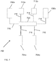
- The invention, in another aspect, features a dynamically-balancing vehicle. The vehicle includes a support for supporting a payload, at least a first and second wheel coupled to the support, and a drive coupled to the first and second wheels to dynamically balance the vehicle and provide power to the first and second wheels to propel the vehicle. The vehicle also includes a controller coupled to the drive to control the drive. The vehicle also includes at least a third wheel coupled to the support and disposed fore or aft of the first and second wheels, wherein the combination of the first, second and third wheels maintain the vehicle in a statically-stable state when the vehicle is operating in the statically-stable state, and a braking system comprising brakes coupled to the first and second wheels, and an actuator assembly coupled to the third wheel for engaging and disengaging the brakes, wherein the actuator assembly engages the brakes when the third wheel contacts an underlying surface and disengages the brakes when the third wheel lifts off the underlying surface.
- In some embodiments, the actuator assembly comprises a master cylinder, and the brakes comprise hydraulic brakes, and wherein the braking system comprises a hydraulic line coupling the master cylinder to the hydraulic brakes. In some embodiments, the vehicle includes a fourth wheel coupled to the support that includes a master cylinder, wherein all the master cylinders and the brakes are coupled together by hydraulic lines.
- In some embodiments, each of the brakes is configured to engage in response to one or more master cylinders being compressed. In some embodiments, the vehicle includes a fluid pressure sensor coupled to the hydraulic lines to measure hydraulic pressure in the hydraulic lines to determine the load applied by the underlying surface to the second wheel. In some embodiments, the vehicle includes a brake sensor for providing a brake-state signal to the controller. In some embodiments, the controller is configured to prohibit the vehicle from entering a balancing mode when the brake-state signal is indicative of the brakes being engaged.
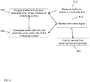
- The invention, in another aspect, features a method for braking a dynamically-balancing vehicle. The vehicle includes a support for supporting a payload, at least a first and second wheel coupled to the support, a drive coupled to the first and second wheels to dynamically balance the vehicle and provide power to the first and second wheels to propel the vehicle, a controller coupled to the drive to control the drive, at least a second wheel coupled to the support and disposed fore or aft of the first and second wheels, wherein the combination of the first, second and third wheels maintain the vehicle in a statically-stable state when the vehicle is operating in the statically-stable state, and a braking system comprising brakes coupled to the first and second wheels, and an actuator assembly coupled to the third wheel. The method includes engaging the brakes with the actuator assembly when the third wheel contacts an underlying surface, and disengaging the brakes with the actuator assembly when the third wheel lifts off the underlying surface.
- In some embodiments, the actuator assembly includes a master cylinder, and the brakes comprise hydraulic brakes, and wherein the braking system comprises a hydraulic line coupling the master cylinder to the hydraulic brakes. In some embodiments, the vehicle includes a fourth wheel coupled to the support that includes a master cylinder, wherein all the master cylinders and the brakes are coupled together by hydraulic lines. In some embodiments, the method includes engaging each of the brakes in response to one or more master cylinders being compressed.
- In some embodiments, the method includes engaging the brakes with the actuator assembly in response to a master cylinder being compressed. In some embodiments, the method includes measuring hydraulic pressure in the hydraulic line to determine load applied by the underlying surface to the third wheel. In some embodiments, the method includes monitoring a brake-state signal to determine whether the brakes are engaged. In some embodiments, the method includes prohibiting the vehicle from entering a balancing mode when the brake-state signal is indicative of the brakes being engaged.
- The foregoing features of the invention will be more readily understood by reference to the following detailed description, taken with reference to the accompanying drawings, in which:
-
FIG. 1 is a schematic illustration of a vehicle, according to an illustrative embodiment of the invention. -
FIG. 2A is a schematic illustration of a vehicle, according to an illustrative embodiment of the invention. -
FIG. 2B is a schematic illustration of a vehicle, according to an illustrative embodiment of the invention. -
FIG. 3 is a block diagram of a control system for dynamically controlling the stability of a vehicle, according to an illustrative embodiment of the invention. -
FIG. 3A is a block diagram of position of the center of gravity of a vehicle with respect to a ground-contacting element of the vehicle. -
FIG. 3B is a block diagram of an alternative position of the center of gravity of the vehicle ofFIG. 3A with respect to a ground-contacting element of the vehicle. -
FIG. 4 is a block diagram of a controller for controlling the operation of a vehicle, according to an illustrative embodiment of the invention. -
FIG. 5 is a schematic illustration of a vehicle, according to an illustrative embodiment of the invention. -
FIG. 6A is a flowchart of a method for transitioning a vehicle from a statically-stable state to a dynamically-balanced state. -
FIG. 6B is a flowchart of a method for transitioning a vehicle from a dynamically-balanced state to a statically-stable state. -
FIG. 7 is a schematic illustration of a braking system for a vehicle, according to an illustrative embodiment of the invention. -
FIG. 8 is a flowchart of a method for braking a dynamically-balancing vehicle, according to an illustrative embodiment of the invention. -
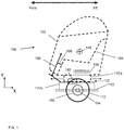
FIG. 1 is a schematic illustration of avehicle 100, according to an illustrative embodiment of the invention. Thevehicle 100 includes anenclosure 102 coupled to asupport 104. Thevehicle 100 also includes at least one ground-contacting element 110 (e.g., one or more wheels) coupled to aplatform 112. The ground-contactingelement 110 rotates about anaxle 114 which is coupled to theplatform 112. Thevehicle 100 also includes acoupling structure 172 that includes asupport portion 172a coupled to thesupport 104 and aplatform portion 172b coupled to theplatform 112. Thecoupling structure 172 allows thesupport portion 172a to move or slide for and aft with respect to theplatform portion 172b. - In this embodiment, the
coupling structure 172 is a slide assembly, and thesupport portion 172a is a rail and theplatform portion 172b is a rail guide. In this embodiment, a human subject (not shown) manipulates aninput device 106 to cause a position of a center ofgravity 140 of thevehicle 100 to change. Theinput device 106 is coupled to alinkage 108. Thelinkage 108 is coupled to thesupport 104. Theinput device 106 can be, for example, a control stick, yoke, steering wheel or handlebar. - The human subject pushes the
input device 106 forward (toward the negative X-Axis direction) which moves theenclosure 102 andsupport 104 forward (toward the negative X-Axis direction) relative to the ground-contactingelement 110. The position of the center ofgravity 140 of thevehicle 100 moves forward in response to theenclosure 102 andsupport 104 moving forward. A forward torque is generated by the ground-contactingelement 110 in response to the center ofgravity 140 of thevehicle 100 moving forward. The human subject pulls theinput device 106 backward (toward the human subject's body and along the positive X-Axis direction) which moves theenclosure 102 andsupport 104 backward (toward the positive X-Axis direction) relative to the ground-contactingelement 110. The position of the center ofgravity 140 of thevehicle 100 moves backward in response to theenclosure 102 andsupport 104 moving backward. A negative torque is generated by the ground-contactingelement 110 in response to the position of the center ofgravity 140 of thevehicle 100 moving backward. - The
vehicle 100 also includes anactuator 190 coupled to thecoupling structure 172 to control the position of thesupport portion 172a relative to theplatform portion 172b. Thevehicle 100 also includes adrive 180 coupled to theplatform 112 and the ground-contactingelement 110. The drive 180 (e.g., a motorized drive) delivers power to the ground-contactingelement 110 to cause rotation of the ground-contactingelement 110 to propel/move the vehicle fore (towards the negative X-Axis direction) and aft (towards the positive X-Axis direction). Thedrive 180 also maintains theplatform 112 at a desired orientation (e.g., level or a desired variation near level) with respect to gravity. In some embodiments, thevehicle 100 includes two or more laterally disposed (along the Z-axis, with the positive direction along the Z-axis is out of the page) ground-contactingelements 110 which assist with providing lateral stability to thevehicle 100. - The
vehicle 100 also includes at least one controller 194 (e.g.,controller 400 ofFIG. 4 ) coupled to thedrive 180 to control thedrive 180 and coupled to theactuator 190 to control theactuator 190. Thecontroller 194 controls balancing of thevehicle 100 in response to the position of theenclosure 102 andsupport 104 relative to the ground-contactingelement 110 andplatform 112. A human subject (not shown) manipulates theinput device 106 to command thedrive 180 to command rotation of the ground-contactingelement 110 to move thevehicle 100 in the fore and aft directions. - In some embodiments, when the
enclosure 102,support 104 andsupport portion 172a slide forward or backward relative to theplatform portion 172b,platform 112 and ground-contactingelement 110, theenclosure 102,support 104 andsupport portion 172a remain at a desired orientation (e.g., level or desired variation near level) relative to the underlying surface/ground. In alternative embodiments, when theenclosure 102,support 104 andsupport portion 172a slide forward or backward relative to theplatform portion 172b,platform 112 and ground-contactingelement 110, theenclosure 102,support 104 andsupport portion 172a pitch relative to the ground. Thevehicle 100 can be adapted such thatenclosure 102,support 104 andsupport portion 172a pitch forward when theenclosure 102,support 104 andsupport portion 172a slide forward, or alternatively, adapted such thatenclosure 102,support 104 andsupport portion 172a pitch backward when theenclosure 102,support 104 andsupport portion 172a slide forward. - In some embodiments, the human subject shifts his/her weight forward or backward to move the position of the center of gravity to cause the vehicle to move forward or backward, respectively, without causing the
enclosure 102,support 104 andsupport portion 172a to move relative to theplatform portion 172b,platform 112 and the ground-contactingelement 110. - In some embodiments, the
linkage 108 is coupled to a device that provides stiffness or damping to movement of thelinkage 108 to, for example, enforce particular types of inputs to the vehicle and/or enhance the human subject's experience. In some embodiments, the device limits the speed that thelinkage 108 is permitted to move which limits the speed at which the position of the center ofgravity 140 is permitted to change and, therefore, limits the rate of change of the speed of thevehicle 100. - In some embodiments, the device damps oscillations in the movement of the
linkage 108 to reduce oscillations in the pitch control loop and/or center of gravity control loop of a controller that controls operation of thevehicle 100. In the absence of the device, oscillations induced in thelinkage 108 by, for example, a human subject pushing or pulling theinput device 106 would result in oscillations in the pitch and/or speed of thevehicle 100. - In some embodiments, the
support portion 172a and/orplatform portion 172b includes a damper to prevent the speed of thevehicle 100 from oscillating when thesupport portion 172a moves out of phase with respect to theplatform portion 172b due to, for example, an external disturbance or on-vehicle disturbance. For example, when thevehicle 100 travels over a bump, thesupport portion 172a may move or slide relative to theplatform portion 172b, thereby moving the position of the center ofgravity 140 of thevehicle 100. Movement of the position of the center ofgravity 140 fore or aft causes thevehicle 100 to accelerate or decelerate. Therefore, a damper coupling thesupport portion 172a to theplatform portion 172b would reduce the high frequency motion otherwise induced by the bump, and reduce the variation in the speed of thevehicle 100 due to the bump. The damper would not damp lower frequency motions introduced, for example, by a human subject pushing the input device1 to command a change to the position of the center ofgravity 140 of the vehicle. In some embodiments, the damper is configured to damp high frequency oscillations or impulses. The damper can be a mechanical damper coupling thesupport portion 172a to theplatform portion 172b. In some embodiments, the damper is a damping term implemented in thecontroller 194. -
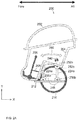
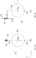
FIG. 2A is a schematic illustration of avehicle 200, according to an illustrative embodiment of the invention. Theenclosure 202 is coupled to thesupport 204. The at least one ground-contactingelement 210 is coupled to theplatform 212. The ground-contactingelement 210 rotates about theaxle 214. Thevehicle 200 also includes a coupling structure that is at least one four-bar linkage 224 (combination offirst bar 224a andsecond bar 224b). Afirst end 252a of thefirst bar 224a is coupled to thesupport 204 and afirst end 252b of thesecond bar 224b is coupled to thesupport 204.First end 252a andfirst end 252b of the bars are the support portion of the coupling structure. Asecond end 256a of thefirst bar 224a is coupled to theplatform 212 and asecond end 256b of thesecond bar 224b is coupled to theplatform 212.Second end 256a andsecond end 256b of the bars are the platform portion of the coupling structure. - The
enclosure 202 andsupport 204 move along apath 260 defined by a rotation of the four-bar linkage 224 in the X-Y plane. In this embodiment, a human subject (not shown) manipulates aninput device 206 to cause the position of the center ofgravity 240 of thevehicle 200 to change. Theinput device 206 is coupled to thelinkage 208. Thelinkage 208 is coupled to thesupport 204. The human subject pushes theinput device 206 forward (toward the negative X-Axis direction) which moves theenclosure 202 andsupport 204 along thepath 260 defined by the rotation of the four-bar linkage 224, moving theenclosure 202 andsupport 204 forward (toward the negative X-Axis direction) relative to the ground-contactingelement 210. The position of the center ofgravity 240 of thevehicle 200 moves forward in response to theenclosure 202 andsupport 204 moving forward. A forward torque is generated by the ground-contactingelement 210 in response to the position of the center ofgravity 240 of thevehicle 200 moving forward. - The human subject pulls the
input device 206 backward (toward the human subject's body and along the positive X-Axis direction) which moves theenclosure 202 andsupport 204 along thepath 260 defined by the rotation of the four-bar linkage 224, moving theenclosure 202 andsupport 204 backward (toward the positive X-Axis direction) relative to the ground-contactingelement 210. The position of the center ofgravity 240 of thevehicle 200 moves backward in response to theenclosure 202 andsupport 204 moving backward. A negative torque is generated by the ground-contactingelement 210 in response to the position of the center ofgravity 240 of thevehicle 200 moving backward. - In some embodiments, the
vehicle 200 includes two laterally disposed ground-contacting elements. The vehicle also includes two four-bar linkages (e.g., two of the four-bar linkages 224). Each four-bar linkage is coupled to one of the two laterally disposed ground-contacting elements. In some embodiments, one or more four-bar linkages are flexible bars. The flexible bars bend to permit, for example, the enclosure and support to move along a path (e.g., thepath 260 ofFIG. 2A ). -
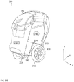
FIG. 2B is a three-dimensional view of avehicle 268, according to an illustrative embodiment of the invention. A human subject (not shown) rests on asupport 272 in anenclosure 276 that at least partially encloses the human subject. Thevehicle 268 includes twowheels wheels platform 280.Wheel 260 is laterally disposed towheel 264. The wheels each rotate about anaxle 284 and are powered by at least one drive 288 (e.g., a motorized drive). A controller (292) is coupled to thedrive 288 for providing a control signal in response to changes in vehicle orientation (e.g., pitch) and position of the center ofgravity 296 of thevehicle 268. - As the human subject mounts the
vehicle 268, thecontroller 292 implements a control loop and senses a change in the vehicle's 268 orientation that can result from a change in the position of the center ofgravity 296 in a fore-aft plane and controls power provided to thewheels gravity 296. In response to the change in the vehicle's 268 orientation and changes in the position of the center ofgravity 296, torque is applied to thewheels vehicle 268, similarly as described inU.S. Patent Application No. 12/266.170 (the entire contents of which are hereby incorporated by reference in its entirety). - In one embodiment, as the position of the center of
gravity 296 moves in a fore direction (toward the negative X-Axis direction), thedrive 288 provides power to the twowheels vehicle 268 to move forward (toward the negative X-Axis direction). As the center ofgravity 296 moves in the aft direction (toward the positive X-Axis direction), thedrive 288 provides power to the twowheels vehicle 268 to slow and reverse direction such that thevehicle 268 moves backward (toward the positive X-Axis direction. - The pitch of the vehicle 268 (angular orientation of the
vehicle 268 about the axle 284) may also be sensed and compensated for in the control loop. The controller includes gyroscopes for sensing orientation of thevehicle 268 that can result from changes in the position of the center ofgravity 296. -
Vehicle 268 pitch variation is decreased during operation when thevehicle 268 is dynamically stabilized based on the change in the position of the support portion relative to the platform portion (e.g.,support portion 172a andplatform portion 172b ofFIG. 1 ) rather than in response to a change in pitch. It also shortens the time it takes thevehicle 268 to respond to an acceleration and/or deceleration command. Thevehicle 268 accelerates and/or decelerates by restoring the position of the center ofgravity 296 of thevehicle 268 over the location that thewheels vehicle 268 was accelerated and/or decelerated in response to a change in pitch, a controller of thevehicle 268 would first need to induce a change in the position of the center ofgravity 296 relative to a steady state position and then command thedrive 288 to operate thewheels gravity 296 above the location where the ground-contacting elements contact the ground. The time required to induce a change in the position of the center ofgravity 296 back to the steady state position is a time delay for thevehicle 268 to respond to an acceleration and/or deceleration command compared to acceleration and/or deceleration in response to a change in the position of the center of gravity. Thevehicle 268 does not need to induce the change in the position of the center ofgravity 296 from a steady state because the change of the position of the center ofgravity 296 is inherent in the acceleration and/or deceleration command. The acceleration and/or deceleration command necessitates a change in the orientation of thevehicle 268 to position the center ofgravity 296 in the correct position so that acceleration and/or deceleration can begin. -
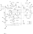
FIG. 3 is a block diagram of acontrol system 300 for dynamically controlling the stability of a vehicle having two laterally disposed wheels (e.g.,wheels FIG. 2B ), according to an illustrative embodiment of the invention. A controller 302 (e.g.,controller 400 ofFIG. 4 ) receives an input characteristic of a position of the support portion (e.g.,support portion 172a ofFIG. 1 ) relative to the platform portion (e.g.,platform portion 172b ofFIG. 1 ) which affects the location of the center of gravity of the vehicle, from asensor module 304. Based on at least the position of the support portion relative to the platform portion provided by thesensor module 304, thecontroller 302 commands torque T of at least one of the leftmotorized drive 306 or right motorized drive 308 (e.g., torque applied to the corresponding ground-contacting elements). -
FIGS. 3A and 3B are block diagrams that illustrate the effect of the position of the center ofgravity 322 of avehicle 330 on operation of thevehicle 330, according to an illustrative embodiment of the invention. Thevehicle 330 has a total mass M2 (weight of M2g). The mass of a payload and a portion of thevehicle 330 is denoted as M1 (weight of M1g) which corresponds to the mass of the center ofgravity 322. The mass of two laterally disposed contactingelements 320 is denoted as mass M0 (weight of M0g). The weight of thevehicle 330 is expressed as:
vehicle 330 capable of moving along the X-Axis direction relative to the position of the ground-contactingelements 320 is represented by the center ofgravity 322. Referring toFIG. 3A , the center ofgravity 322 is located at aninitial location 334 above thelocation 338 where the ground-contactingelements 320 contact the ground. - Referring to
FIG. 3B , the center ofgravity 322 is located at alocation 342, at a distance L along the negative X-Axis direction relative to theinitial location 334. In one embodiment, the center ofgravity 322 is positioned atlocation 342 by a human subject moving the position of the center of gravity of thevehicle 330. The sensor module 304 (ofFIG. 3 ) provides the pitch of thevehicle 330 and the orientation of thevehicle 330 to thecontroller 302. The pitch and orientation change as theposition 342 of the center ofgravity 322 changes. Thecontroller 302 outputs a signal to the leftmotorized drive 306 and rightmotorized drive 308 to apply a torque [T=(M1g)(L)] to the ground-contactingelements 320 to cause the ground-contactingelements 320 to move in the direction (e.g., forward along the negative X-Axis direction) the center ofgravity 322 has been displaced from theprevious location 338 to maintain balance of thevehicle 330. - The masses of the
vehicle 330 can be advantageously distributed between the payload and related structure (collectively 322) and the ground contacting-elements and related structure (collectively 320) to maximize acceleration and deceleration performance. In one embodiment, it is advantageous to locate a larger percentage of thetotal vehicle 330 mass with the moving portion of the vehicle 330 (i.e., with the payload and related structure 322) to maximize acceleration and deceleration performance. Placing more of thetotal vehicle 330 mass with the movingportion 322 enables the larger amount of mass to contribute to generating the motor commands required to accelerate or decelerate thevehicle 330. If, however, more of thetotal vehicle 330 mass was placed with the ground-contacting elements andrelated structure 320, the larger percentage of mass would be a load that thevehicle 330 needs to move as part of theentire vehicle 330. - The
controller 302 also interfaces with auser interface 310 and awheel rotation sensor 312. Theuser interface 310 can, for example, include controls for turning the vehicle on or off, or for triggering different operating modes of the vehicle. - The
sensor module 304 detects one or more vehicle parameters to determine a change in the position of the center of gravity of the vehicle (e.g., due to movement of thesupport portion 172a relative to theplatform portion 172b of thevehicle 100 ofFIG. 1 ). In one embodiment, thesensor module 304 generates a signal indicative of a change in the position of the center of gravity at one instance in time with respect to the position of the center of gravity at another instance in time. For example, a distance sensor attached to a spring, a load sensor, an inclinometer, a gyroscope, whiskers and/or an angular rate sensor can be used to determine a change in the center of gravity of the vehicle. Other sensors (e.g., optical sensors and/or magnetic sensors) can also be employed and are therefore within the scope of the present invention. - The
controller 302 includes a control algorithm to determine the amount of torque to be applied by the leftmotorized drive 306 and/or rightmotorized drive 308 based on the slide position (i.e., support portion relative to the platform portion). The control algorithm can be configured, for example, during the design of the vehicle or in real time, on the basis of a current operating mode of the vehicle, operating conditions experienced by the vehicle, as well as preferences of a human subject. - As an example, not meant to be limiting, the control algorithm can take the form:

- The gain, K, can be a predetermined constant, or can be entered or adjusted by the human subject through the
user interface 310. Gain K is, most generally, a vector, with the torque determined as a scalar product of the gain and the position of the slide displacement vector. Responsiveness of the vehicle to changes in the position of the slide can be governed by K. For example, increasing the magnitude of at least one element of vector K causes a human subject to perceive a stiffer response in that a small change in the position of the slide results in a large torque command. - Offset, O, can be incorporated into the control algorithm to govern the torque applied to the left
motorized drive 306 and rightmotorized drives 308, either in addition to, or separate from, the direct effect of C. Thus, for example, the human subject can provide an input by means of the user interface 310 (e.g.,input 106 ofFIG. 1 ), the input is treated by thecontroller 302 equivalently to a change, for example, in the position of the slide. - In one embodiment, steering can be accomplished by calculating the torque desired for the left
motorized drive 306 and the torque desired for the rightmotorized drive 308 separately. Additionally, tracking both the left wheel motion and the right wheel motion permits adjustments to be made, as known to persons of ordinary skill in the control arts, to prevent unwanted turning of the vehicle and to account for performance variations between the leftmotorized drive 306 and the rightmotorized drive 308. - Steering may be accomplished in an embodiment having at least two laterally disposed ground-contacting elements (e.g., a left and right wheel), by providing, for example, separate motors for left and right ground-contacting elements. Torque desired for the left motor and the torque desired for the right motor can be calculated separately. Additionally, tracking both the left ground-contacting element motion and the right ground-contacting element motion with the ground-contacting
element rotation sensors 312 permits adjustments to be made, as known to persons of ordinary skill in the control arts, to prevent unwanted turning of the vehicle and to account for performance variations between the two motors. In some embodiments, steering sensitivity is adjusted to a higher sensitivity when a vehicle is at lower speeds and lower sensitivity when a vehicle is at higher speeds to allow, for example, easier steering at higher speeds. - In some embodiments, the
control system 300 limits the speed of the vehicle. The speed limit can be set based on, for example, a maximum speed associated with the operating mode of the vehicle or an input from the human subject. - In one embodiment, the
control system 300 includes a speed limiting algorithm that regulates the speed of the vehicle by controlling the pitch of the vehicle. Thecontroller 302 changes the pitch of the vehicle which moves the position of the center of gravity. Changes in the position of the center of gravity cause the vehicle to accelerate or decelerate depending on which direction the center of gravity is moved. The speed limiting algorithm causes thecontroller 302 to limit the speed of the vehicle by adjusting a desired pitch angle Θ D . The pitch control loop of thesystem 300 controls thesystem 300 to achieve the desired pitch angle Θ D . - The adjustment of the desired pitch angle θD is determined based on the following relationship:

control system 300 to control the speed of the vehicle. - In one embodiment, the desired pitch angle θD remains constant (e.g., the vehicle remains level with respect to the ground plane). When a predefined maximum speed limit is reached, the
control system 300 responds by setting the desired pitch angle θD to a value to decelerate the vehicle to prevent the vehicle from exceeding the maximum speed limit. This has the effect of thecontrol system 300 commanding the vehicle to pitch backwards which causes the speed of the vehicle to decrease. - In some embodiments, the
control system 300 is configured to account for the human subject commanding the vehicle to slow down. When thecontrol system 300 determines that the human subject has caused the position of the center of gravity to shift rearward, the controller reduces the value of the gain K1. By reducing the value of the gain K1, the pitch angle terms in the control system 300 (governed by, for example, EQN. 3) are de-emphasized. Because thecontrol system 300 de-emphasizes the pitch angle terms, thecontrol system 300 does not command the vehicle to pitch backwards as much as it would in the absence of the human subject commanding the vehicle to slow down. -
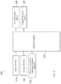
FIG. 4 is a block diagram of acontroller 400 for controlling the operation of a vehicle (e.g.,vehicle 100 ofFIG. 1 ), according to an illustrative embodiment of the invention. The vehicle's dynamic response to a rider's 402 or a controller's 404 (e.g., autonomous) input commands, terrain, payload, wind load, and system capability can be managed by a number of nested and cooperative closed-loop system controllers. Thepitch controller 406 maintains dynamic stability of the vehicle. Thepitch controller 406 can take feedback data from various sources, for example, pitch andpitch rate 408 from the pitch state estimator (PSE) 410, andslide position 412 from slide-mounted string potentiometer 414 (or, an other suitable sensor that provides a measure of the position of, for example, the support portion of the coupling structure relative to the platform portion of the coupling structure). The pitch controller 416 can output wheel motor speed commands 418 to keep the vehicle chassis (e.g., support) level. - The vehicle's
yaw controller 466 can take, as input, steering commands from the HMI 402 (or the controller 404) and compare the steering commands 420 to the wheels speeds 422 from the wheel motor drives 424 to create wheel motorspeed command components 426 needed to steer and turn the vehicle. The wheel motor speed commands 438 can include a command component for the vehicle's propulsion and a command component for the vehicle's steering. In some embodiments, thesteering command component 426 is added to the propulsion command component 418 (from the pitch controller 406) for one wheel and subtracted from thepropulsion component 418 for the other wheel. - The vehicle's
velocity controller 428 can take, as input, vehicle speed commands 430 from the HMI 402 (or the controller 404), that have, if necessary, been limited by the vehicle'sspeed limiter 432. The vehicle'svelocity controller 428 can create slide position commands 434 to adjust the position of the slide affecting the position of the CG and thus, adjust torque applied by the wheels to an underlying surface to adjust the acceleration and speed of the vehicle. The vehicle'svelocity controller 428 can receive velocity feedback from both thewheel 422 and theslide 436 motor drives. - Wheel
speed command components pitch 406 andyaw 466 controllers and can be combined to create overall motor speed commands 438 that the vehicle can use to balance, steer and drive the vehicle. The resulting wheel speed commands 438 can be sent to wheel motor drives 424 which can control the speeds of thewheel motors 442. The wheel motor drives 424 can be digitally controlled, sine modulated, and permanent magnet motor drives. - A
slide position command 434 can be output from the vehicle'svelocity controller 428, which may be limited by theeffort limiter 444, can be input to aslide position controller 446. Theslide position controller 446 compares theslide position command 434 to theactual slide position 412 from the string potentiometer and outputs slidemotor speed command 448. Themotor speed command 448 can be input to slideactuator motor drive 450 which can control the slide'smotor 468 speed. - Inside the vehicle's wheel motor drives 424, there can be motor speed loops to control motor current loops which can control duty cycles of power bridges that can output varying 3-phase voltages to the vehicle's
wheel motors 442. The vehicle'swheel motor positions 458 can be fed back to the wheel motor drives 424 frommotor shaft encoders 460 for commutation and for closing the speed loop. The speed controllers can be configured with proportional gains. Thus, a steady-state speed error can develop under a load. The presence of a steady-state speed error can help ensure that loads carried by redundant motors, if implemented, are shared in a reasonably well-balanced fashion. A current limiter in eachwheel motor drive 424 can protect the motor drives 424 and theirmotors 442 from overheating while allowing peak torque capability for short durations and continuous torque capability for indefinite periods of operation. - In order to know how much to limit the effort demanded of the propulsion system, the wheel motor current capability can be estimated. The motor current capability can be estimated by knowing the present motor speed, current and current limits, which can be fed back from the wheel motor drives 424, and the estimated battery resistance and open-circuit voltage from the battery state estimator (BSE) 452. Thus, the
BSE 452 can use the current and terminal voltage fed back from thebattery 456 to estimate the battery resistance by monitoring how much the battery voltage changes in response to battery current changes. TheBSE 452 can estimate the open-circuit battery voltage (the no-load voltage) from the actual battery current and terminal voltage and the battery's estimated resistance. - Using as inputs the battery state estimates from the
BSE 452, and the motor current, current limit and speed feedback from the wheel motor drives 424, the motor current capability estimator (CCE) 454 can estimate the motor current that the vehicle's propulsion system can produce at any point in time. The current capability can be passed to theeffort limiter 444, which limits the slide position to keep a margin between the commanded current and the current capability of the system, thus balancing and steering capability can be maintained. The vehicle's motor drives 424 can include current limiting algorithms to adjust the vehicle's motor current between peak and continuous limits. The limits are selected to protect both themotors 442 and thedrives 424. Any time the commanded or target current is above a drive's continuous limit, the drive's enforced limit can slew down to the drive's continuous limit. When the motor target current drops below the continuous limit, the enforced limit can slew back up to the peak limit. The enforced limits can be fed back from thedrives 424 to theCCE 454. - The vehicle's
speed limiter 432 can set the top speed limit of the system and implement a slowdown response that can be requested by the vehicle'ssafety kernel 462. Thus, thespeed limiter 432 can pass aspeed limit value 464 to the vehicle'svelocity controller 428, which enforces it. As thesafety kernel 462 determines that a slowdown response is needed, it can request a slowdown response from thespeed limiter 432. Thespeed limiter 432 can calculate a time-varying speed limit that can be used for the slowdown response and pass the time-varying speed values to thevelocity controller 428. - There are several responses to hazards and
faults 466 that thesafety kernel 462 can issue that can result in changing the speed limit. For example, limit-speed response, zero-speed response, full-system safety shutdown, and half-system safety shutdown (for redundant systems). They are similar in the fact that they can all cause the system to decelerate; and differ on the values they can limit to and the rates they can cause the system to decelerate at. Additionally, safety shutdown responses can be coupled with landing (transitioning to a statically-stable state) and power down commands once the system has reached zero speed. - The vehicle's limit-speed response can be issued under transient conditions such as when an inertial measurement unit (IMU) 470 is "dizzy". Once the transient condition disappears (e.g., no longer turning fast) the limit on speed can be slowly lifted. The zero-speed response can be issued, for example, if the conditions causing the limit-speed response persist, and the system can set the speed limit to zero fairly rapidly.
- The safety shutdown responses can be issued when the system has encountered a fault that requires the system to come to rest and power down. A safety shutdown brings the system to zero speed. The rate at which the system is brought to zero speed can vary with the type of safety shutdown. In cases where the full system is available, the system can decelerate at the maximum possible rate to minimize the time the system remains on while faulted. For redundant systems in the half-system case, the slowdown rate can be cut in half because the system only has half capability and trying to decelerate at maximum full system rates can increase the likelihood of saturating the half-system capability. The
speed limiter 432 can inform thesafety kernel 462 when it has achieved its task, but sometimes can delay the feedback to ensure, for example, that the system dynamics have settled before issuing land and power-down commands. - The
pitch controller 406 can use estimated feedback data for pitch andpitch rate 408. These estimates can be calculated in the Pitch State Estimator (PSE) 410 from raw angular rate and accelerometer data from theIMU 470. - The
pitch controller 406 can be a closed-loop controller and can be the primary balancing function. Thepitch controller 406 has as inputs information about the desired and measured pitch orientations of the vehicle with respect to gravity and can create commands for the actuators to provide stabilizing forces. These forces, while providing stability in the pitch axis, concurrently provide a propulsive force for the general fore/aft motion of the vehicle. Theoutput 418 of thepitch controller 406 is a component of the overall propulsion command and can be added to the other components in another module. - The
pitch controller 406 can include four terms, the sum of which can constitute the pitch command. The first term can be a gain applied to the difference between the desired and measured/estimated pitch, also known as the "error." The product of the gain and the error is commonly referred to as a "proportional term." When applied to the balancing vehicle, the proportional term drives the vehicle in the direction of the vehicle pitch or "lean." An additional degree of freedom represented by the linear slide actuator can require compensation in the first term of the pitch controller. A pitch offset can be applied as a function of the slide position. The pitch offset term offsets a desired pitch by a current slide position multiplied by an empirically-derived gain. This can be done to compensate for the increasing torque demand on the wheel actuator as the distance to the overhung load is increased in magnitude. The distance to the overhung load is calculated as the fore/aft distance from the neutral balance point (not from the center of slide travel). The second term can be a gain applied to the pitch rate data. This term is commonly referred to as a "rate term." A rate term opposes pitch motion, and thus can resist changes in orientation. It can be a source of damping in the controller. - The third term can be for a motor drive that controls speed or voltage. It can be a "feed-forward term" based on average speed of the left and right wheel motors. This term can be used to provide some steady state command for a given vehicle speed so as to reduce the need for pitch error to grow as speed increases. This term can be unnecessary for the pitch controller when directly commanding motor current. The fourth term can be for slide motion compensation. As the slide moves it imparts disturbance forces on the system. This term can be a "feed-forward term" based on slide motion. The term can be used to provide some damping when there is relative motion between the support portion of the coupling structure of the vehicle relative to the platform portion of the coupling structure of the vehicle. It can perform the function of adding damping when the pitch loop is excited by any relative motion between the support portion relative to the platform portion.
- In one embodiment, the method is implemented using a velocity controller (referring to the
vehicle velocity controller 428 ofFIG. 4 used to control operating speed ofvehicle 100 ofFIG. 1 ). The velocity controller is a closed-loop controller that regulates the fore/aft motion of the vehicle. It accomplishes this through the combined effects of controlling theslide controller 446 and thepitch controller 406. Thevelocity controller 428 calculates a desired position for the slide which the slide position controller carries out. The resulting shift in the position of the center of gravity (CG) in turn can induce motion by causing pitch error, and thus wheel motion can be driven by the pitch controller. - The
velocity controller 428 can be a high-level controller that can utilize lower-level controllers directly (slide) and indirectly (pitch) to control the plant. The output of the velocity controller can be a desired slide position that feeds the slide controller. By positioning theenclosure 102,support 104, andsupport portion 172a of thecoupling structure 172 and battery mass relative to thewheels 110, thevelocity controller 428 can induce commands in the pitch loop which in turn can give rise to vehicle accelerations which the velocity controller can utilize to achieve its goal. - The target of the velocity loop can be calculated from one of two sources, either the manual controls 402 or the
controller 404. Thevelocity controller 428 is capable of switching between these two sources while the loop is closing to achieve the operational goals of the system, including mode switching on the fly. Thevelocity controller 428 can have a proportional term and an integral term. The integral term can be important for several reasons. It can provide the system with its station-keeping capability on flat ground, inclined surfaces, in the presence of external disturbances (e.g., wind) and compensate for the variation in system losses that occur over the working speed range to effectively achieve the target. - The
velocity controller 428 feedback is a combination ofwheel velocity 422 and slidevelocity 436. This can be important for the stability of the velocity loop. Consider a hypothetical case where the system is at rest and thevelocity controller 428 is using only the average of all the present wheel speeds as feedback. If forward speed is desired, the slide can be moved forward. As the slide moves forward, there is a reaction force on the chassis which can cause the wheels to roll backwards. This rolling backwards can increase the velocity error and push the slide further forward, which in turn can increase the backward rolling and so forth creating positive feedback. By taking the vehicle velocity to be the sum of the average of the present wheel and slide speeds this undesired response can be remedied because as the wheels are moving back the slide can be moving forward which can have the tendency to cancel the effect. - The reverse mode of operation can be implemented by setting limits on the velocity target based upon the forward/reverse state. In the reverse mode some small speed limit can be allowed (e.g., less than 3 mph) and in forward mode no reverse motion can be allowed. Forward motion commands can be allowed in both modes; forward mode can be thought of as a reverse motion inhibit mode. Transitions between modes can be regulated by system dynamic data and a mode input switch (e.g., operable by a user or autonomous controller). In one embodiment, to enable reverse mode when in forward mode, the criteria can be: the system speed must be low, the velocity target must be low, and the forward/reverse mode button must be pressed. The request can be not latched. To enable forward mode when in reverse mode, one can toggle modes with same criteria for entering reverse mode or push the throttle input forward if the system is at zero speed.
-
FIG. 5 is a schematic illustration of avehicle 500, according to an illustrative embodiment of the invention. Thevehicle 500 is similar to thevehicle 100 ofFIG. 1 and, common reference numbers refer to common elements. Thevehicle 500 includeslanding gear 504 that is coupled to thevehicle 500. In this embodiment, thelanding gear 504 includes awheel 508. When thevehicle 500 is pitched forward (rotated alongcurve 528 toward the fore direction) by a predetermined amount, thelanding gear 504 is in contact with theunderlying surface 532. The combination of thelanding gear 504 and the at least onewheel 110 maintain thevehicle 500 in a statically-stable state. In one embodiment, the at least onewheel 110 is a plurality of laterally disposed wheels. In another embodiment, thelanding gear 504 is a plurality of skids, pads, or wheel assemblies that provide lateral stability to thevehicle 500 when thevehicle 500 is not powered. In this embodiment, thelanding gear 504 is located fore of the at least onewheel 110; however, in some embodiments, thelanding gear 504 is located aft of the at least onewheel 110. - The
vehicle 500 also includes amaster cylinder 512 coupled to thelanding gear 504 and a brake 516 (e.g., a hydraulic caliper brake) coupled to the at least onewheel 110. Themaster cylinder 512 is coupled to thebrake 516 by ahydraulic line 520. The combination of the master cylinder andhydraulic line 520 form an actuator system for engaging and disengaging thebrake 516. Alternative actuator systems can be used to actuate thebrake 516 in response to, for example, a predetermined condition being satisfied (e.g., load applied to the landing gear). Themaster cylinder 512 converts non-hydraulic pressure (e.g., displacement of a piston in themaster cylinder 512 from contact with the underlying surface 532) into hydraulic pressure in thehydraulic line 520 to actuate thebrake 516. The vehicle can also include abrake sensor 524 that monitors thevehicle 500 to determine if thebrake 516 is engaged. In one embodiment, thebrake sensor 524 is a fluid pressure sensor coupled to thehydraulic line 520 to measure fluid pressure in the hydraulic braking system. The combination of themaster cylinder 512,brake 516,hydraulic line 520 and thebrake sensor 524 form a braking system for thevehicle 500. -
FIG. 6A is a flowchart of a method for transitioning a vehicle (e.g., thevehicle 500 ofFIG. 5 ) from a statically-stable state to a dynamically-balanced state. The method includes controlling (604) the drive (e.g., thedrive 180 ofFIG. 5 ) to command the at least one wheel (e.g.,wheel 110 ofFIG. 5 ) to hold a zero speed condition and to hold the vehicle in a stationery position with respect to an underlying surface. The method also includes controlling (608) the actuator (e.g.,actuator 190 ofFIG. 5 ) to move the position of the support portion of the coupling structure relative to the platform portion of the coupling structure to alter the position of the center of gravity of the vehicle towards a location where the vehicle is capable of balancing with the at least one wheel. - The method also includes determining if a predetermined condition has been satisfied (612). If the predetermined condition has not been satisfied, the vehicle (e.g., a controller of the vehicle) continues to monitor the operation of the vehicle to determine when the predetermined condition has been satisfied. If the predetermined condition has been satisfied, the method then proceeds with initiating (616) dynamic balancing of the vehicle with the at least one wheel (e.g.,
wheel 110 ofFIG. 5 ). In some embodiments, the system determines whether the location of the vehicle center of gravity satisfies the predetermined condition. In one embodiment, the predetermined condition is satisfied when a load applied by the underlying surface to the vehicle landing gear (e.g.,landing gear 504 ofFIG. 5 ) is less than a predefined amount. In some embodiments, the system determines the load applied by the underlying surface to the landing gear using a fluid pressure sensor coupled to a hydraulic braking system that is coupled to the vehicle landing gear. - In some embodiments, the predetermined condition is satisfied when the vehicle pitches backward and the landing gear is no longer in contact with the underlying surface. In some embodiments, the predetermined condition is satisfied when the position of the support portion relative to the platform portion approaches a predefined threshold position (e.g., a position at which the position of the vehicle center of gravity is above the at least one wheel used to balance and propel the vehicle).
- The method also includes controlling (620) the position of the support portion relative to the platform portion and controlling pitch of the vehicle to level the support. By way of example, at the point where the dynamic balancing controller is enabled, the support and platform are still tilted forward essentially as far as the support and platform were located when parked/stopped. The balancing (pitch) and slide position controllers then work together to adjust the support and platform tilt to a level state. This is done by slewing the desired pitch (via the pitch controller) from the parked angle to zero (e.g., leveling
platform 112 ofFIG. 1 ) while maintaining zero wheel velocity and position (via the speed controller). The method also includes controlling (624) the drive to disable the command that held the at least one wheel to a zero speed condition and held the vehicle in a stationery position with respect to the underlying surface. An operator may then, for example, command the vehicle to move. -
FIG. 6B is a flowchart of a method for transitioning a vehicle (e.g.,vehicle 500 ofFIG. 5 ) from a dynamically-balanced state to a statically-stable state. The method includes commanding the actuator (640) to control the position (e.g., using thecontroller 400 ofFIG. 4 ) of the support portion of the vehicle coupling structure relative to the platform portion of the vehicle coupling structure to hold a zero speed condition and to hold the vehicle in stationery position with respect to an underlying surface. The method also includes controlling the drive (648) to pitch the vehicle forward while maintaining the vehicle in a dynamically-balanced state. The method also, optionally, includes preventing (644) the vehicle from pitching backward after commanding the actuator to control the position of the support portion relative to the platform portion to hold a zero speed condition and to hold the vehicle in a stationery position with respect to the underlying surface. - The method also includes determining if a landing configuration condition has been satisfied (652). If the landing configuration condition has not been satisfied, the vehicle (e.g., a controller of the vehicle) continues to monitor the operation of the vehicle to determine when the landing configuration condition has been satisfied. When the landing configuration condition has been satisfied, the method then terminates dynamic balancing of the vehicle (660). The method also, optionally, includes commanding (656) the actuator to move the support portion relative to the ground portion in a direction towards the landing gear. By way of example, one motivation for performing
step 656 prior to step 660, is to guarantee that the vehicle CG position is located some distance towards the landing gear and that the platform is at least somewhat statically-stable prior to terminating dynamic balancing of the vehicle (656). The method also includes moving (664) the support portion relative to the ground portion in a direction towards the landing gear following terminating balancing of the vehicle. - In some embodiments, the landing configuration condition is satisfied when a load applied by the underlying surface to the landing gear is greater than a predefined amount. In some embodiments, the load applied by the underlying surface to the landing gear is determined using a fluid pressure sensor coupled to a hydraulic braking system coupled to the landing gear of the vehicle (e.g., the braking system of
FIG. 5 ). In some embodiments, the landing configuration condition is satisfied when the landing gear is in contact with the underlying surface. In some embodiments, the landing configuration condition is satisfied when the position of the support portion relative to the ground portion approaches a predefined threshold position (e.g., a position at which the position of the vehicle center of gravity is generally located between the landing gear and the at least one wheel (e.g.,wheel 110 ofFIG. 5 )). -
FIG. 7 is a schematic illustration of abraking system 700 for a vehicle, according to an illustrative embodiment of the invention. Thebraking system 700 may be used as, for example, a braking system for thevehicle 500 ofFIG. 5 . Thebraking system 700 includes twomaster cylinders landing gear 504 ofFIG. 5 laterally disposed relative to each other). Loads applied by the underlying surface to the landing gear are coupled to the master cylinders 704. Thebraking system 700 also includes twohydraulic brakes - The master cylinders 704 and brakes 708 are coupled together using
hydraulic lines 716. The master cylinders 704, brakes 708 andhydraulic lines 716 are coupled together via acommon manifold block 720. Themanifold block 720 causes the brakes 708 to be subject to the same hydraulic line pressure. When a load is applied to the landing gear/wheels, pistons in the master cylinders move and compress the hydraulic fluid in the hydraulic lines which increases the hydraulic pressure. The pressure in the hydraulic lines causes the brakes 708 to engage. When the load is removed from the landing gear/wheels, the pressure decreases in the hydraulic lines causing the brakes 708 to disengage. Two master cylinders 704 are used, and coupled to both brakes 708, to allow both brakes 708 to engage even if only one of the landing gear assemblies supports the vehicle (e.g., as when on uneven pavement). - The
braking system 700 also includes two pressure sensors/switches controller 400 ofFIG. 4 ). In some embodiments, the controller prohibits the vehicle from entering a balancing mode when the brake-state signal is indicative of the brakes being engaged. -
FIG. 8 is a flowchart of a method for braking a dynamically-balancing vehicle, according to an illustrative embodiment of the invention. The vehicle includes a support for supporting a payload, at least a first and second wheel coupled to the support, a drive coupled to the first and second wheels to dynamically balance the vehicle and provide power to the first and second wheels to propel the vehicle, a controller coupled to the drive to control the drive, at least a second wheel coupled to the support and disposed fore or aft of the first and second wheels, wherein the combination of the first, second and third wheels maintain the vehicle in a statically-stable state when the vehicle is operating in the statically-stable state, and a braking system comprising brakes coupled to the first and second wheels, and an actuator assembly coupled to the third wheel. The method includes engaging the brakes with the actuator assembly when the third wheel contacts an underlying surface (804). The method also includes disengaging the brakes with the actuator assembly when the third wheel lifts off the underlying surface (808). - In some embodiments, the actuator assembly for the braking system includes a master cylinder, the brakes are hydraulic brakes, and the braking system also includes hydraulic lines that couple the master cylinder to the hydraulic brakes.
- In embodiments where the system includes hydraulic brakes and hydraulic lines, the method also includes measuring hydraulic pressure in the hydraulic lines to determine when a load is applied by the underlying surface to the third wheel (812). In these embodiments,
step 804 is implemented in response to a load being applied by the underlying surface to the third wheel. The method also includes monitoring a brake-state signal (816) to determine whether the brakes are engaged. If a controller (e.g.,controller 194 ofFIG. 5 ) determines the brakes are engaged, the controller prohibits the vehicle from entering a balancing mode (820). - The described embodiments of the invention are intended to be merely exemplary and numerous variations and modifications will be apparent to those skilled in the art. All such variations and modifications are intended to be within the scope of the present invention as defined in any appended claims.
Claims (15)
- A dynamically-balancing vehicle (500), the vehicle comprising:a support (104) for supporting a payload;at least a first and second wheel (110) coupled to the support (104);a drive (180) coupled to the first and second wheels (110) to dynamically balance the vehicle and provide power to the first and second wheels (110) to propel the vehicle (500);a controller (194) coupled to the drive (180) to control the drive; andat least a third wheel (508) coupled to the support (104) and disposed fore or aft of the first and second wheels (110), wherein the combination of the first, second and third wheels (110, 508) maintain the vehicle (500) in a statically-stable state when the vehicle (500) is operating in the statically-stable state;characterized in that:a braking system (700) comprising brakes (516) is coupled to the first and second wheels (110), andan actuator assembly for engaging and disengaging the brakes (516) is coupled to the third wheel (508) and to the braking system (700),wherein the actuator assembly can cause the brakes (516) to engage when the third wheel (508) contacts an underlying surface and can cause the brakes (516) to disengage when the third wheel (508) lifts off the underlying surface.
- The vehicle of claim 1, wherein the actuator assembly comprises a master cylinder (704), and the brakes (508) comprise hydraulic brakes (516), and wherein the braking system comprises a hydraulic line (520, 716) coupling the master cylinder (704) to the hydraulic brakes (708).
- The vehicle of claim 2, wherein the vehicle comprises a fourth wheel coupled to the support that includes a master cylinder (704), wherein all the master cylinders (704) and the hydraulic brakes (708) are coupled together by hydraulic lines (716).
- The vehicle of claim 3, wherein each of the hydraulic brakes (708) is configured to engage in response to one or more master cylinders (704) being compressed.
- The vehicle of claim 3, comprising a fluid pressure sensor (712) coupled to the hydraulic lines (716) to measure hydraulic pressure in the hydraulic lines (716) to determine the load applied by the underlying surface to the third wheel (508).
- The vehicle of claim 1, comprising a brake sensor for providing a brake-state signal to the controller (194).
- The vehicle of claim 5, wherein the controller (194) is configured to prohibit the vehicle from entering a balancing mode when the brake-state signal is indicative of the brakes being engaged.
- A method for braking a dynamically-balancing vehicle (500), the vehicle comprising a support (104) for supporting a payload, at least a first and second wheel (110) coupled to the support, a drive (180) coupled to the first and second wheels (110) to dynamically balance the vehicle and provide power to the first and second wheels (110) to propel the vehicle (500), a controller (194) coupled to the drive (180) to control the drive, at least a third wheel (508) coupled to the support (104) and disposed fore or aft of the first and second wheels (110), wherein the combination of the first, second and third wheels (110, 508) maintain the vehicle (500) in a statically-stable state when the vehicle (500) is operating in the statically-stable state, a braking system (700) comprising brakes (516) coupled to the first and second wheels (110), and an actuator assembly for engaging and disengaging the brakes (516) coupled to the third wheel (508) and to the braking system (700),
characterized in that the method further comprises:engaging the brakes (516) with the actuator assembly when the third wheel (508) contacts an underlying surface; anddisengaging the brakes (516) with the actuator assembly when the third wheel (508) lifts off the underlying surface. - The method of claim 8, wherein the actuator assembly comprises a master cylinder (704), and the brakes (516) comprise hydraulic brakes (708), and wherein the braking system comprises a hydraulic line (716) coupling the master cylinder (704) to the hydraulic brakes (708).
- The method of claim 9, wherein the vehicle comprises a fourth wheel coupled to the support that includes a master cylinder (704), wherein all the master cylinders (704) and the hydraulic brakes (708) are coupled together by hydraulic lines (716).
- The method of claim 10, further comprising engaging each of the hydraulic brakes (708) in response to one or more master cylinders (704) being compressed.
- The method of claim 9, further comprising engaging the hydraulic brakes (708) with the actuator assembly in response to the master cylinder (704) being compressed.
- The method of claim 9, further comprising measuring hydraulic pressure in the hydraulic line (716) to determine load applied by the underlying surface to the third wheel (508).
- The method of claim 8, further comprising monitoring a brake-state signal (816) to determine whether the brakes (508) are engaged.
- The method of claim 14, further comprising prohibiting the vehicle from entering a balancing mode when the brake-state signal is indicative of the brakes (508) being engaged.
Applications Claiming Priority (2)
| Application Number | Priority Date | Filing Date | Title |
|---|---|---|---|
| US30865910P | 2010-02-26 | 2010-02-26 | |
| EP11714144.0A EP2539216B1 (en) | 2010-02-26 | 2011-02-28 | Apparatus and method for control of a vehicle |
Related Parent Applications (1)
| Application Number | Title | Priority Date | Filing Date |
|---|---|---|---|
| EP11714144.0A Division EP2539216B1 (en) | 2010-02-26 | 2011-02-28 | Apparatus and method for control of a vehicle |
Publications (2)
| Publication Number | Publication Date |
|---|---|
| EP2979964A1 EP2979964A1 (en) | 2016-02-03 |
| EP2979964B1 true EP2979964B1 (en) | 2017-08-09 |
Family
ID=43902892
Family Applications (3)
| Application Number | Title | Priority Date | Filing Date |
|---|---|---|---|
| EP11709522.4A Active EP2544944B1 (en) | 2010-02-26 | 2011-02-28 | Apparatus and methods for control of a vehicle |
| EP11714144.0A Active EP2539216B1 (en) | 2010-02-26 | 2011-02-28 | Apparatus and method for control of a vehicle |
| EP15183279.7A Active EP2979964B1 (en) | 2010-02-26 | 2011-02-28 | Apparatus and method for control of a vehicle |
Family Applications Before (2)
| Application Number | Title | Priority Date | Filing Date |
|---|---|---|---|
| EP11709522.4A Active EP2544944B1 (en) | 2010-02-26 | 2011-02-28 | Apparatus and methods for control of a vehicle |
| EP11714144.0A Active EP2539216B1 (en) | 2010-02-26 | 2011-02-28 | Apparatus and method for control of a vehicle |
Country Status (7)
| Country | Link |
|---|---|
| US (5) | US8688303B2 (en) |
| EP (3) | EP2544944B1 (en) |
| JP (4) | JP5848266B2 (en) |
| CN (3) | CN102811901B (en) |
| ES (1) | ES2547959T3 (en) |
| HK (3) | HK1179582A1 (en) |
| WO (2) | WO2011106767A2 (en) |
Families Citing this family (142)
| Publication number | Priority date | Publication date | Assignee | Title |
|---|---|---|---|---|
| US7275607B2 (en) | 1999-06-04 | 2007-10-02 | Deka Products Limited Partnership | Control of a personal transporter based on user position |
| US7210544B2 (en) | 2002-07-12 | 2007-05-01 | Deka Products Limited Partnership | Control of a transporter based on attitude |
| US8800697B2 (en) | 2009-09-01 | 2014-08-12 | Ryno Motors, Inc. | Electric-powered self-balancing unicycle with steering linkage between handlebars and wheel forks |
| JP2012197748A (en) * | 2011-03-22 | 2012-10-18 | Toyota Motor Corp | Vehicle control apparatus |
| DE112011105397B4 (en) * | 2011-06-28 | 2021-08-19 | Hitachi, Ltd. | Inverse pendulum-type moving body with speed planning device |
| US8403095B1 (en) * | 2011-12-05 | 2013-03-26 | Bryce A. Ecklein | Step on-step off motorized utility vehicle |
| US8738278B2 (en) * | 2012-02-12 | 2014-05-27 | Shane Chen | Two-wheel, self-balancing vehicle with independently movable foot placement sections |
| CN104160183B (en) * | 2012-03-07 | 2017-08-25 | 克拉克设备公司 | Power management for drive system |
| GB201207989D0 (en) * | 2012-05-04 | 2012-06-20 | Control Tech Ltd | Method of optimising input components |
| US9067598B2 (en) * | 2012-06-14 | 2015-06-30 | GM Global Technology Operations LLC | Method and apparatus for controlling a high-voltage electrical system for a multi-mode transmission |
| EP2888155A4 (en) | 2012-08-22 | 2016-08-03 | Ryno Motors Inc | Electric-powered self-balancing unicycle |
| ITMI20121785A1 (en) * | 2012-10-22 | 2014-04-23 | 4Ward S R L | SELF-BALANCING MOBILE ROBOTIC DEVICE FOR THE SUPPORT OF ADVERTISING AND / OR MULTIMEDIA MATERIAL |
| JP2014125191A (en) * | 2012-12-27 | 2014-07-07 | Kubota Corp | Vehicle capable of being operated by movement of center of gravity |
| JP6095436B2 (en) | 2013-03-27 | 2017-03-15 | 本田技研工業株式会社 | Inverted pendulum type vehicle |
| JP6081271B2 (en) | 2013-03-29 | 2017-02-15 | 本田技研工業株式会社 | Inverted pendulum type vehicle |
| JP6111119B2 (en) * | 2013-03-29 | 2017-04-05 | 本田技研工業株式会社 | Inverted pendulum type vehicle |
| JP6081270B2 (en) | 2013-03-29 | 2017-02-15 | 本田技研工業株式会社 | Inverted pendulum type vehicle |
| EP2985169B1 (en) * | 2013-04-12 | 2020-12-16 | Mitsubishi Electric Corporation | Propulsion control device and propulsion control method |
| CN104108445B (en) * | 2013-04-19 | 2016-07-27 | 光阳工业股份有限公司 | Individual's transport carrier |
| CN103213630B (en) * | 2013-04-19 | 2015-07-29 | 东北大学 | A kind of Double-wheel self-balancing trolley |
| WO2014182527A1 (en) | 2013-05-06 | 2014-11-13 | Future Motion, Inc. | Self-stabilizing skateboard |
| CN103253152A (en) * | 2013-05-14 | 2013-08-21 | 杭州亿脑智能科技有限公司 | Method for determining torque of motor of balance car |
| JP6099485B2 (en) | 2013-05-31 | 2017-03-22 | 本田技研工業株式会社 | Inverted pendulum type vehicle |
| JP6099484B2 (en) | 2013-05-31 | 2017-03-22 | 本田技研工業株式会社 | Inverted pendulum type vehicle |
| US20140366711A1 (en) * | 2013-06-17 | 2014-12-18 | Perry Woo | Roman Shield Cycle (RSC) |
| USD784852S1 (en) * | 2013-06-19 | 2017-04-25 | Shenzhen Zhiyou Battery Integration Technology Co., Ltd | Vehicle |
| KR101533256B1 (en) * | 2013-06-20 | 2015-07-02 | 주식회사 아이휠 | Self-stabilized vehicle having two wheels |
| US20150137557A1 (en) * | 2013-11-18 | 2015-05-21 | Brandon Thomas | Temperature-Controlled Personal Mobility Device Enclosure |
| US9244460B2 (en) * | 2013-12-31 | 2016-01-26 | GM Global Technology Operations LLC | Methods and apparatus for isolating safety functions in a motion control system for a vehicle |
| FR3018748B1 (en) * | 2014-03-24 | 2016-04-15 | Lyon Smart Design | MOTORCYCLE HAS ONE WHEEL TRAIN |
| US9452097B2 (en) * | 2014-03-31 | 2016-09-27 | Clive Lu | Electric mobility vehicle |
| WO2015157653A1 (en) * | 2014-04-10 | 2015-10-15 | Segway Inc. | Electrical vehicle with control system |
| CN104014123A (en) | 2014-06-13 | 2014-09-03 | 杭州骑客智能科技有限公司 | Longitudinal double-wheel vehicle body |
| TWI607926B (en) * | 2014-08-29 | 2017-12-11 | 國立清華大學 | Displacement equipment and power-assisted system |
| USD746928S1 (en) | 2014-10-20 | 2016-01-05 | Future Motion, Inc. | Skateboard |
| US9452345B2 (en) | 2014-11-05 | 2016-09-27 | Future Motion, Inc. | Rider detection system |
| CN105640721A (en) * | 2014-11-26 | 2016-06-08 | 深圳市优威埃科技有限公司 | Balance car wheelchair |
| JP6197784B2 (en) * | 2014-12-18 | 2017-09-20 | トヨタ自動車株式会社 | Inverted moving body |
| DE202015000910U1 (en) | 2015-02-04 | 2015-03-02 | Norbert Neubauer | Drainage device for wound treatment |
| DE202015004507U1 (en) * | 2015-06-25 | 2016-09-29 | Isel Facility GmbH | Vehicle for transporting loads or passengers |
| US9809264B1 (en) * | 2015-07-20 | 2017-11-07 | The United States Of America, As Represented By The Secretary Of The Navy | Track kit for two wheeled balancing ground vehicle |
| CN105109601A (en) * | 2015-08-17 | 2015-12-02 | 华钟祥 | Dual-drive balance wheelchair |
| DE102015217327B4 (en) | 2015-09-10 | 2018-01-25 | Uwe Bernhard | Dynamically balancing vehicle |
| DE102015217341A1 (en) | 2015-09-10 | 2017-03-16 | Uwe Bernhard | Dynamically balancing vehicle |
| DE102015217342B4 (en) | 2015-09-10 | 2023-06-29 | Uwe Bernhard | Dynamically balancing vehicle |
| US10252724B2 (en) | 2015-09-24 | 2019-04-09 | P&N Phc, Llc | Portable two-wheeled self-balancing personal transport vehicle |
| DE102015219847B3 (en) * | 2015-10-13 | 2017-03-23 | Uwe Bernhard | Dynamically balancing vehicle |
| DE102015219848B3 (en) * | 2015-10-13 | 2017-02-16 | Uwe Bernhard | Dynamically balancing vehicle |
| DE102015219881A1 (en) | 2015-10-14 | 2017-05-04 | Uwe Bernhard | Dynamically balancing vehicle |
| DE102015222687A1 (en) | 2015-11-17 | 2017-05-18 | Uwe Bernhard | Vehicle with operating unit |
| CA3003165A1 (en) | 2015-11-25 | 2017-06-01 | Voxx International Corporation | Stability attachment for a two-wheeled, self-balancing, personal transportation vehicle |
| WO2017124120A1 (en) * | 2016-01-17 | 2017-07-20 | Chen, Shane | Self-balancing load bearing vehicle |
| US10926756B2 (en) | 2016-02-23 | 2021-02-23 | Deka Products Limited Partnership | Mobility device |
| MX2021007862A (en) | 2016-02-23 | 2022-09-22 | Deka Products Lp | Mobility device control system. |
| US10802495B2 (en) | 2016-04-14 | 2020-10-13 | Deka Products Limited Partnership | User control device for a transporter |
| US11399995B2 (en) | 2016-02-23 | 2022-08-02 | Deka Products Limited Partnership | Mobility device |
| US10908045B2 (en) | 2016-02-23 | 2021-02-02 | Deka Products Limited Partnership | Mobility device |
| US10112680B2 (en) | 2016-03-07 | 2018-10-30 | Future Motion, Inc. | Thermally enhanced hub motor |
| US9598141B1 (en) | 2016-03-07 | 2017-03-21 | Future Motion, Inc. | Thermally enhanced hub motor |
| CN105810007B (en) * | 2016-03-29 | 2020-07-03 | 北京小米移动软件有限公司 | Balance car parking method and device |
| US10059397B2 (en) * | 2016-04-15 | 2018-08-28 | Hui Zheng | Self-balancing vehicle with gravity control |
| KR20170032822A (en) | 2016-04-22 | 2017-03-23 | 김대우 | Apparatus and methods for control of a vehicle by gyroscope |
| CN105786010B (en) * | 2016-05-11 | 2021-01-29 | 上海明我信息技术有限公司 | Anti-falling control method and device and electronic equipment |
| WO2017210549A1 (en) | 2016-06-02 | 2017-12-07 | Future Motion, Inc. | Vehicle rider detection using strain gauges |
| DE102016110435B4 (en) | 2016-06-06 | 2020-01-16 | Universität Kassel | Uniaxial vehicle, control device and method for controlling such a vehicle |
| CN107472419A (en) * | 2016-06-07 | 2017-12-15 | 韩莹光 | A kind of method for adjusting gravity center of balance car |
| CN107536698B (en) * | 2016-06-29 | 2022-06-03 | 松下知识产权经营株式会社 | Walking assistance robot and walking assistance method |
| USD941948S1 (en) | 2016-07-20 | 2022-01-25 | Razor Usa Llc | Two wheeled board |
| USD840872S1 (en) | 2016-07-20 | 2019-02-19 | Razor Usa Llc | Two wheeled board |
| USD807457S1 (en) | 2016-07-20 | 2018-01-09 | Razor Usa Llc | Two wheeled board |
| USD803963S1 (en) | 2016-07-20 | 2017-11-28 | Razor Usa Llc | Two wheeled board |
| USD837323S1 (en) | 2018-01-03 | 2019-01-01 | Razor Usa Llc | Two wheeled board |
| WO2018025172A1 (en) * | 2016-08-02 | 2018-02-08 | B-Free Limited | Hybrid wheeled and tracked moving mechanism |
| DE102016116371A1 (en) * | 2016-09-01 | 2018-03-01 | Fabio Giuseppe Gulino | Self-balancing transport device, in particular wheelchair with damping |
| JP6497368B2 (en) * | 2016-09-13 | 2019-04-10 | トヨタ自動車株式会社 | Traveling device |
| TWI644824B (en) | 2016-10-11 | 2018-12-21 | 美商未來運行公司 | Suspension system for one-wheeled vehicle |
| JP2020503204A (en) | 2016-10-18 | 2020-01-30 | ピアジオ ファスト フォワード インク | Vehicle with off-axis drive and stabilization system |
| WO2018081315A1 (en) | 2016-10-25 | 2018-05-03 | Future Motion, Inc. | Self-balancing skateboard with strain-based controls and suspensions |
| USD890024S1 (en) * | 2016-12-06 | 2020-07-14 | Piaggio Fast Forward, Inc. | Vehicle |
| USD821517S1 (en) | 2017-01-03 | 2018-06-26 | Future Motion, Inc. | Skateboard |
| KR102442228B1 (en) * | 2017-01-13 | 2022-09-13 | 크라운 이큅먼트 코포레이션 | Suppression of high-speed front tiller sensitivity |
| CN108341001A (en) * | 2017-01-23 | 2018-07-31 | 北京凌云智能科技有限公司 | Sulky vehicle balance system and its control method |
| DE102017205080B4 (en) | 2017-03-27 | 2021-05-06 | Ford Motor Company | Motor vehicle with a mobile vehicle seat and a mobile vehicle seat |
| CN106970621B (en) * | 2017-04-17 | 2021-03-30 | 北京京东乾石科技有限公司 | Transfer robot operation control method and device and robot |
| CN108791616A (en) * | 2017-04-27 | 2018-11-13 | C·J·鲁宾 | Self-balancing electronic swing car and its control method |
| JP6601805B2 (en) * | 2017-04-28 | 2019-11-06 | 株式会社Subaru | vehicle |
| CN106963571B (en) * | 2017-05-03 | 2018-07-13 | 江苏师范大学 | A kind of Multifunctional walking-assistant tool |
| US20180335773A1 (en) * | 2017-05-16 | 2018-11-22 | Yi Xie | Balancing board |
| USD829612S1 (en) | 2017-05-20 | 2018-10-02 | Deka Products Limited Partnership | Set of toggles |
| USD846452S1 (en) | 2017-05-20 | 2019-04-23 | Deka Products Limited Partnership | Display housing |
| DE102017211838B4 (en) | 2017-07-11 | 2023-07-06 | Uwe Bernhard | Dynamically balancing vehicle |
| CN107444560B (en) * | 2017-07-25 | 2019-08-13 | 广西机电职业技术学院 | A kind of cell apparatus of auto balancing electric vehicle |
| DE102017222318A1 (en) | 2017-12-08 | 2019-06-13 | Uwe Bernhard | Dynamically balancing vehicle |
| DE102017217103A1 (en) | 2017-09-26 | 2019-03-28 | Uwe Bernhard | Dynamically balancing vehicle |
| EP3459834A1 (en) | 2017-09-26 | 2019-03-27 | Armin Maurer | Dynamically balancing vehicle |
| IT201700114497A1 (en) | 2017-10-11 | 2019-04-11 | Piaggio Fast Forward Inc | TWO-WHEEL VEHICLE WITH LINEAR STABILIZATION SYSTEM |
| GB2607190B (en) * | 2017-11-15 | 2023-05-03 | Sway Motorsports Llc | Control system for a tiltable vehicle |
| DE102017010996A1 (en) * | 2017-11-28 | 2019-05-29 | Daimler Ag | Car and method for operating a motor vehicle |
| WO2019109102A1 (en) | 2017-12-01 | 2019-06-06 | Future Motion, Inc. | Control system for electric vehicles |
| US10010784B1 (en) | 2017-12-05 | 2018-07-03 | Future Motion, Inc. | Suspension systems for one-wheeled vehicles |
| WO2019113537A1 (en) | 2017-12-07 | 2019-06-13 | Future Motion, Inc. | Dismount controls for one-wheeled vehicle |
| CN111527023B (en) | 2017-12-22 | 2023-01-13 | 美国锐哲有限公司 | Electric balance car |
| DE102018200826A1 (en) * | 2018-01-18 | 2019-07-18 | Robert Bosch Gmbh | vehicle |
| USD850552S1 (en) | 2018-02-23 | 2019-06-04 | Future Motion, Inc. | Skateboard |
| USD843532S1 (en) | 2018-02-23 | 2019-03-19 | Future Motion, Inc. | Skateboard |
| DE102018206143A1 (en) | 2018-04-20 | 2019-10-24 | Uwe Bernhard | Dynamically balancing vehicle |
| CA3098000C (en) | 2018-05-01 | 2021-12-07 | Piaggio Fast Forward, Inc. | Method for determining self-driving vehicle behavior models, a self-driving vehicle, and a method of navigating a self-driving vehicle |
| WO2019237031A1 (en) | 2018-06-07 | 2019-12-12 | Deka Products Limited Partnership | System and method for distributed utility service execution |
| EP3598959A1 (en) * | 2018-07-27 | 2020-01-29 | Scewo AG | Self-balancing vehicle |
| DE102018217512A1 (en) * | 2018-10-12 | 2020-04-16 | Continental Teves Ag & Co. Ohg | Steering vehicle control |
| US11408498B2 (en) | 2018-10-22 | 2022-08-09 | Piaggio Fast Forward, Inc. | Shifting assembly and mobile carrier comprising same |
| USD911405S1 (en) | 2018-10-22 | 2021-02-23 | Piaggio Fast Forward, Inc. | Mobile carrier |
| US11479311B2 (en) | 2019-01-07 | 2022-10-25 | Future Motion, Inc. | Self-balancing systems for electric vehicles |
| US10456658B1 (en) | 2019-02-11 | 2019-10-29 | Future Motion, Inc. | Self-stabilizing skateboard |
| EP3927564A1 (en) * | 2019-02-19 | 2021-12-29 | Sway Motorsports LLC | Autonomous tilting delivery vehicle |
| US11072389B2 (en) | 2019-02-22 | 2021-07-27 | Sway Motorsports Llc | Three-wheeled tilting vehicle |
| JP2022521935A (en) | 2019-02-22 | 2022-04-13 | スウェイ モータースポーツ エルエルシー | Inclined tricycle |
| USD881307S1 (en) | 2019-03-11 | 2020-04-14 | Future Motion, Inc. | Fender for electric vehicle |
| USD890278S1 (en) | 2019-03-11 | 2020-07-14 | Future Motion, Inc. | Electric vehicle |
| USD890280S1 (en) | 2019-03-11 | 2020-07-14 | Future Motion, Inc. | Rider detection sensor for electric vehicle |
| USD890279S1 (en) | 2019-03-11 | 2020-07-14 | Future Motion, Inc. | Electric vehicle with fender |
| USD888175S1 (en) | 2019-03-11 | 2020-06-23 | Future Motion, Inc. | Electric vehicle front |
| USD897469S1 (en) | 2019-03-11 | 2020-09-29 | Future Motion, Inc. | Foot pad for electric vehicle |
| USD881308S1 (en) | 2019-03-11 | 2020-04-14 | Future Motion, Inc. | Fender for electric vehicle |
| USD886929S1 (en) | 2019-03-11 | 2020-06-09 | Future Motion, Inc. | Rear bumper for electric vehicle |
| USD889577S1 (en) | 2019-03-11 | 2020-07-07 | Future Motion, Inc. | Rotatable handle for electric vehicle |
| CN109946979B (en) * | 2019-04-25 | 2022-03-22 | 广东省智能机器人研究院 | Self-adaptive adjusting method for sensitivity function of servo system |
| FI3741609T3 (en) * | 2019-05-22 | 2023-08-31 | Sandvik Mining & Construction Oy | Method and arrangement for controlling electric current in tether cable of a mining vehicle |
| WO2020254966A1 (en) * | 2019-06-17 | 2020-12-24 | Vapenjeri Jayarama Reddy Anil Kumar | Bodyshell retrofitted to two-wheeler with conditional balancing system |
| DE102019219920A1 (en) * | 2019-12-17 | 2021-06-17 | UrmO GmbH | STEERING CONTROL OF A PERSONAL TRANSPORT DEVICE |
| USD947287S1 (en) | 2020-01-31 | 2022-03-29 | Ryan McLean | Three-wheel scooter |
| CA3208914A1 (en) * | 2020-02-04 | 2021-08-12 | Movex Innovation Inc. | Inclination control system for tracked vehicle |
| JP7360972B2 (en) | 2020-02-25 | 2023-10-13 | 東芝テック株式会社 | Sales data processing equipment and programs |
| US20220177058A1 (en) * | 2020-12-08 | 2022-06-09 | Bryant Engineering & Development, LLC | Self-Stabilizing Two-Wheeled Vehicle |
| US11952072B2 (en) * | 2020-12-08 | 2024-04-09 | Bryant Engineering & Development, LLC | Self-stabilizing vehicle |
| TWI753734B (en) * | 2021-01-04 | 2022-01-21 | 新普科技股份有限公司 | Method and device for estimating a maximum load capable of continuous drawing for a duration of the battery |
| KR20220109141A (en) * | 2021-01-28 | 2022-08-04 | 삼성전자주식회사 | Moving robot apparatus and controlling method thereof |
| EP4092264A1 (en) * | 2021-05-19 | 2022-11-23 | Wobben Properties GmbH | Method for operating a wind turbine, wind turbine, and wind farm |
| US11273364B1 (en) | 2021-06-30 | 2022-03-15 | Future Motion, Inc. | Self-stabilizing skateboard |
| US11299059B1 (en) | 2021-10-20 | 2022-04-12 | Future Motion, Inc. | Self-stabilizing skateboard |
| DE102022205030A1 (en) | 2022-05-19 | 2023-11-23 | Uwe Bernhard | Dynamically self-balancing single-axle two-wheel vehicle |
| US11890528B1 (en) | 2022-11-17 | 2024-02-06 | Future Motion, Inc. | Concave side rails for one-wheeled vehicles |
Family Cites Families (185)
| Publication number | Priority date | Publication date | Assignee | Title |
|---|---|---|---|---|
| US584127A (en) | 1897-06-08 | Edmond draullette and ernest catois | ||
| US693132A (en) * | 1900-12-03 | 1902-02-11 | Axel Heiden | Car. |
| US734109A (en) | 1901-09-20 | 1903-07-21 | Henry Tolcher | Monocycle. |
| FR980237A (en) | 1949-02-07 | 1951-05-09 | Baby carriage or crawler stroller | |
| US3145797A (en) | 1960-09-21 | 1964-08-25 | Charles F Taylor | Vehicle |
| US3260324A (en) | 1963-11-12 | 1966-07-12 | Caesar R Suarez | Motorized unicycle |
| US3399742A (en) | 1966-06-23 | 1968-09-03 | Franklin S. Malick | Powered unicycle |
| US3446304A (en) | 1966-08-08 | 1969-05-27 | Constantin Alimanestiand | Portable conveyor |
| US3580344A (en) | 1968-12-24 | 1971-05-25 | Johnnie E Floyd | Stair-negotiating wheel chair or an irregular-terrain-negotiating vehicle |
| US4088199A (en) | 1976-02-23 | 1978-05-09 | Wolfgang Trautwein | Stabilized three-wheeled vehicle |
| BE841212A (en) | 1976-04-28 | 1976-08-16 | SPORTS VEHICLE | |
| JPS538932A (en) * | 1976-07-12 | 1978-01-26 | Tokyu Car Corp | Trailer with parking brake |
| US4062558A (en) | 1976-07-19 | 1977-12-13 | David Wasserman | Unicycle |
| US4094372A (en) | 1977-02-28 | 1978-06-13 | Notter Michael A | Motorized skateboard with uni-directional rear mounting |
| US4109741A (en) | 1977-07-29 | 1978-08-29 | Gabriel Charles L | Motorized unicycle wheel |
| US4222449A (en) | 1978-06-08 | 1980-09-16 | Feliz Jack M | Step-climbing wheel chair |
| US4293052A (en) | 1978-07-17 | 1981-10-06 | Daswick Alexander C | Lightweight two-wheeled vehicle |
| DE2915387A1 (en) | 1979-04-14 | 1980-10-16 | Heinz Eichholz | ELECTRIC VEHICLE |
| US4373600A (en) | 1980-07-18 | 1983-02-15 | Veda, Inc. | Three wheel drive vehicle |
| JPS5787766A (en) | 1980-11-19 | 1982-06-01 | Waseda Daigaku | Monocycle |
| US4566707A (en) | 1981-11-05 | 1986-01-28 | Nitzberg Leonard R | Wheel chair |
| AU554344B2 (en) | 1982-06-09 | 1986-08-14 | Jeco Co. Ltd. | Magnetically damped angle change detector |
| GB2139576A (en) | 1983-05-13 | 1984-11-14 | Mavispace Ltd | Stair climbing devices |
| JPS6025302U (en) | 1983-07-22 | 1985-02-21 | アツプリカ葛西株式会社 | electric children's rides |
| FR2576863A1 (en) | 1985-01-31 | 1986-08-08 | Brunet Pierre | MOTORIZED DISPLACEMENT DEVICE, FOR EXAMPLE FOR RUNNING AND DESCENDING STAIRS |
| GB8515992D0 (en) | 1985-06-25 | 1985-07-31 | Hester R | Wheelchair |
| JPS6212810A (en) | 1985-07-10 | 1987-01-21 | Hitachi Ltd | Measuring instrument |
| JPS6260403A (en) * | 1985-09-06 | 1987-03-17 | Nippon Denso Co Ltd | Controller for electric rolling stock |
| US4657272A (en) | 1985-09-11 | 1987-04-14 | Davenport James M | Wheeled vehicle |
| US4624469A (en) | 1985-12-19 | 1986-11-25 | Bourne Jr Maurice W | Three-wheeled vehicle with controlled wheel and body lean |
| US4716980A (en) | 1986-02-14 | 1988-01-05 | The Prime Mover Company | Control system for rider vehicles |
| US4809804A (en) | 1986-08-25 | 1989-03-07 | Falcon Rehabilitation Products, Inc. | Combination wheelchair and walker apparatus |
| JPS63150176A (en) | 1986-12-15 | 1988-06-22 | 工業技術院長 | Walking control method of dynamic walking robot |
| CA1275296C (en) | 1987-05-04 | 1990-10-16 | Pierre Decelles | Climbing and descending vehicle |
| JP2530652B2 (en) | 1987-06-05 | 1996-09-04 | シ−ケ−ディ株式会社 | Attitude control method for coaxial two-wheeled vehicles |
| DE3800476A1 (en) | 1988-01-11 | 1989-07-20 | Anschuetz & Co Gmbh | METHOD FOR STABILIZING A UNI-AXLE CYCLING VEHICLE AND VEHICLE STABILIZED BY THIS METHOD |
| US4998596A (en) | 1989-05-03 | 1991-03-12 | Ufi, Inc. | Self-propelled balancing three-wheeled vehicle |
| US5248007A (en) | 1989-11-21 | 1993-09-28 | Quest Technologies, Inc. | Electronic control system for stair climbing vehicle |
| US5126585A (en) * | 1990-06-19 | 1992-06-30 | Auckland Uniservices Limited | Uninterruptible power supplies |
| DE4134831C2 (en) | 1991-10-22 | 1995-05-18 | Mannesmann Ag | Arrangement for determining a coefficient of friction information |
| DE69124486T2 (en) | 1990-11-30 | 1997-05-15 | Honda Motor Co Ltd | System for controlling the movement of a walking robot with legs |
| JP3070015B2 (en) | 1990-11-30 | 2000-07-24 | 本田技研工業株式会社 | Travel control system for unstable vehicles |
| JP3280392B2 (en) | 1991-04-01 | 2002-05-13 | アイシン・エィ・ダブリュ株式会社 | Driving force control device for electric vehicle |
| IT1253213B (en) | 1991-10-18 | 1995-07-11 | Tgr Srl | TRACKED, ARTICULATED VEHICLE, ALSO PREPARED FOR WHEEL DRIVING, SUITABLE TO TACKLE ANY TYPE OF ROUTE IN AN INDEPENDENT AND SAFE FORM, INCLUDING THE ASCENT AND DESCENT OF STAIRS, ESPECIALLY SUITABLE FOR DISABLED WHEELCHAIRS |
| US5439240A (en) | 1991-10-21 | 1995-08-08 | Tichenor; Clyde L. | Balance shifted personal carriage |
| US5314034A (en) | 1991-11-14 | 1994-05-24 | Chittal Nandan R | Powered monocycle |
| US5366036A (en) | 1993-01-21 | 1994-11-22 | Perry Dale E | Power stand-up and reclining wheelchair |
| JP2993652B2 (en) | 1993-02-13 | 1999-12-20 | ユニテック 株式会社 | Electric play equipment |
| US6581714B1 (en) | 1993-02-24 | 2003-06-24 | Deka Products Limited Partnership | Steering control of a personal transporter |
| US5971091A (en) | 1993-02-24 | 1999-10-26 | Deka Products Limited Partnership | Transportation vehicles and methods |
| US7090040B2 (en) | 1993-02-24 | 2006-08-15 | Deka Products Limited Partnership | Motion control of a transporter |
| US5701965A (en) | 1993-02-24 | 1997-12-30 | Deka Products Limited Partnership | Human transporter |
| US5975225A (en) | 1993-02-24 | 1999-11-02 | Deka Products Limited Partnership | Transportation vehicles with stability enhancement using CG modification |
| US5638265A (en) * | 1993-08-24 | 1997-06-10 | Gabor; George | Low line harmonic AC to DC power supply |
| JPH0787602A (en) | 1993-09-17 | 1995-03-31 | Matsushita Electric Ind Co Ltd | Protective unit for electric automobile |
| DE4404594C2 (en) | 1994-02-12 | 1996-05-30 | Dieter Wittelsberger | Operating and control device |
| US7103460B1 (en) * | 1994-05-09 | 2006-09-05 | Automotive Technologies International, Inc. | System and method for vehicle diagnostics |
| US20050192727A1 (en) * | 1994-05-09 | 2005-09-01 | Automotive Technologies International Inc. | Sensor Assemblies |
| US6868931B2 (en) | 1994-05-27 | 2005-03-22 | Deka Products Limited Partnership | Speed limiting for a balancing transporter accounting for variations in system capability |
| US6915878B2 (en) | 1994-05-27 | 2005-07-12 | Deka Products Limited Partnership | Self-balancing ladder and camera dolly |
| US6311794B1 (en) | 1994-05-27 | 2001-11-06 | Deka Products Limited Partneship | System and method for stair climbing in a cluster-wheel vehicle |
| CN1055268C (en) * | 1994-06-14 | 2000-08-09 | 布林克斯韦斯特马斯公司 | Self-stabilising directionally controllable vehicle with at least three wheels |
| CA2211738C (en) | 1995-02-03 | 2003-09-16 | Deka Products Limited Partnership | Transportation vehicles and methods |
| US6561294B1 (en) | 1995-02-03 | 2003-05-13 | Deka Products Limited Partnership | Balancing vehicle with passive pivotable support |
| US5701968A (en) | 1995-04-03 | 1997-12-30 | Licile Salter Packard Children's Hospital At Stanford | Transitional power mobility aid for physically challenged children |
| US6059062A (en) | 1995-05-31 | 2000-05-09 | Empower Corporation | Powered roller skates |
| US6050357A (en) | 1995-05-31 | 2000-04-18 | Empower Corporation | Powered skateboard |
| US6003624A (en) | 1995-06-06 | 1999-12-21 | University Of Washington | Stabilizing wheeled passenger carrier capable of traversing stairs |
| JP3451848B2 (en) | 1996-09-10 | 2003-09-29 | トヨタ自動車株式会社 | Drive control device for electric vehicle |
| US6225977B1 (en) | 1997-03-25 | 2001-05-01 | John Li | Human balance driven joystick |
| US5883796A (en) * | 1997-04-07 | 1999-03-16 | Wisconsin Alumni Research Foundation | Dynamic series voltage restoration for sensitive loads in unbalanced power systems |
| WO1999021269A1 (en) * | 1997-10-17 | 1999-04-29 | Continental Teves Ag & Co. Ohg | Method and circuit for reducing voltage dips in battery supply lines |
| US6205391B1 (en) | 1998-05-18 | 2001-03-20 | General Motors Corporation | Vehicle yaw control based on yaw rate estimate |
| AU758135B2 (en) | 1998-10-21 | 2003-03-13 | Deka Products Limited Partnership | Fault tolerant architecture for a personal vehicle |
| US6118676A (en) * | 1998-11-06 | 2000-09-12 | Soft Switching Technologies Corp. | Dynamic voltage sag correction |
| EP1161216B1 (en) | 1999-03-15 | 2005-08-03 | Deka Products Limited Partnership | Control system and method for wheelchair |
| US6553271B1 (en) | 1999-05-28 | 2003-04-22 | Deka Products Limited Partnership | System and method for control scheduling |
| US6405816B1 (en) * | 1999-06-03 | 2002-06-18 | Deka Products Limited Partnership | Mechanical improvements to a personal vehicle |
| US6302230B1 (en) | 1999-06-04 | 2001-10-16 | Deka Products Limited Partnership | Personal mobility vehicles and methods |
| US6789640B1 (en) | 2000-10-13 | 2004-09-14 | Deka Products Limited Partnership | Yaw control for a personal transporter |
| WO2001002920A1 (en) | 1999-06-30 | 2001-01-11 | Deka Products Limited Partnership | Apparatus and method for a pitch state estimator for a personal vehicle |
| DE10009924B4 (en) | 2000-03-01 | 2005-11-17 | Sauer-Danfoss Holding Aps | Device for damping pitching vibrations of a motor vehicle |
| US6268712B1 (en) | 2000-09-26 | 2001-07-31 | Vb Autobatterie Gmbh | Method for determining the starting ability of a starter battery in a motor vehicle |
| US6866107B2 (en) * | 2000-10-13 | 2005-03-15 | Deka Products Limited Partnership | Method and device for battery load sharing |
| KR100978686B1 (en) * | 2000-10-13 | 2010-08-30 | 데카 프로덕츠 리미티드 파트너쉽 | Method for maintaining traction between wheels of a transporter and an underlying surface and device for correcting wheel slippage on vehicle |
| US6288505B1 (en) * | 2000-10-13 | 2001-09-11 | Deka Products Limited Partnership | Motor amplifier and control for a personal transporter |
| US6538411B1 (en) | 2000-10-13 | 2003-03-25 | Deka Products Limited Partnership | Deceleration control of a personal transporter |
| JP3817141B2 (en) * | 2000-12-05 | 2006-08-30 | 矢崎総業株式会社 | Deterioration degree determination method and apparatus for vehicle battery |
| US6573675B2 (en) * | 2000-12-27 | 2003-06-03 | Transportation Techniques Llc | Method and apparatus for adaptive energy control of hybrid electric vehicle propulsion |
| US6622804B2 (en) * | 2001-01-19 | 2003-09-23 | Transportation Techniques, Llc. | Hybrid electric vehicle and method of selectively operating the hybrid electric vehicle |
| EP1247684A1 (en) | 2001-04-06 | 2002-10-09 | Ford Global Technologies, Inc., A subsidiary of Ford Motor Company | Control device for motor vehicle speed governor |
| US6404163B1 (en) * | 2001-06-25 | 2002-06-11 | General Motors Corporation | Method and system for regulating a charge voltage delivered to a battery |
| TW546897B (en) * | 2001-08-31 | 2003-08-11 | Delta Electronics Inc | Electronic circuit apparatus having suppression of harmonics and voltage stabilization function and control method |
| US6657321B2 (en) * | 2001-10-02 | 2003-12-02 | General Electric Company | Direct current uninterruptible power supply method and system |
| GB0210082D0 (en) | 2002-05-02 | 2002-06-12 | Ford Global Tech Inc | Vehicle differential control |
| WO2003106250A2 (en) | 2002-06-14 | 2003-12-24 | Deka Products Limited Partnership | Control features for a balancing transporter |
| EP1539522A2 (en) | 2002-07-12 | 2005-06-15 | Deka Products Limited Partnership | Motion control for a transporter |
| US7210544B2 (en) | 2002-07-12 | 2007-05-01 | Deka Products Limited Partnership | Control of a transporter based on attitude |
| US6685208B1 (en) * | 2002-11-19 | 2004-02-03 | Ross L. Cowie | Balance system for an enclosed fore-and-aft wheeled vehicle |
| US6992452B1 (en) * | 2002-12-02 | 2006-01-31 | Deka Products Limited Partnership | Dynamic current limiting |
| US7324902B2 (en) * | 2003-02-18 | 2008-01-29 | General Motors Corporation | Method and apparatus for generalized recursive least-squares process for battery state of charge and state of health |
| JP3661689B2 (en) * | 2003-03-11 | 2005-06-15 | トヨタ自動車株式会社 | Motor drive device, hybrid vehicle drive device including the same, and computer-readable recording medium storing a program for causing a computer to control the motor drive device |
| JP3986992B2 (en) * | 2003-03-31 | 2007-10-03 | 矢崎総業株式会社 | Battery dischargeable capacity estimation method and apparatus |
| US7091724B2 (en) * | 2003-07-23 | 2006-08-15 | Deka Products Limited Partnership | Model-based fault detection in a motor drive |
| US7078877B2 (en) * | 2003-08-18 | 2006-07-18 | General Electric Company | Vehicle energy storage system control methods and method for determining battery cycle life projection for heavy duty hybrid vehicle applications |
| US6931332B2 (en) * | 2003-10-01 | 2005-08-16 | General Electric Company | Method and system for testing battery connectivity |
| JP4597501B2 (en) | 2003-10-01 | 2010-12-15 | プライムアースEvエナジー株式会社 | Method and apparatus for estimating remaining capacity of secondary battery |
| JP4103781B2 (en) | 2003-11-19 | 2008-06-18 | トヨタ自動車株式会社 | Abnormality monitoring device in load drive circuit |
| US7192040B2 (en) * | 2003-12-17 | 2007-03-20 | Shouchun Xie | Drive mechanism for vehicle |
| US7015667B2 (en) * | 2004-03-24 | 2006-03-21 | General Motors Corporation | Current regulation for a field weakening motor control system and method |
| KR100664123B1 (en) * | 2004-05-06 | 2007-01-04 | 엘지전자 주식회사 | A method and a apparatus of operating with optimized power for mobile phone |
| US7089099B2 (en) * | 2004-07-30 | 2006-08-08 | Automotive Technologies International, Inc. | Sensor assemblies |
| US7209841B2 (en) | 2004-11-15 | 2007-04-24 | Cobasys, Llc | Maximum and minimum power limit calculator for batteries and battery subpacks |
| JP5166251B2 (en) | 2005-05-31 | 2013-03-21 | ブリンクス・ウェストマース・ビーブイ | Vehicle and method of controlling vehicle tilt |
| JP2006340560A (en) * | 2005-06-06 | 2006-12-14 | Fujitsu Ten Ltd | Battery state supervisory system, battery state supervising method, and battery supervising device |
| US7648148B1 (en) * | 2005-07-06 | 2010-01-19 | Bombardier Recreational Products Inc. | Leaning vehicle with tilting front wheels and suspension therefor |
| JP4872276B2 (en) * | 2005-09-02 | 2012-02-08 | トヨタ自動車株式会社 | Traveling body |
| JP2007118807A (en) * | 2005-10-28 | 2007-05-17 | Equos Research Co Ltd | Vehicle |
| JP4201793B2 (en) | 2005-11-30 | 2008-12-24 | 大王製紙株式会社 | Cutter equipment |
| JP4887865B2 (en) * | 2005-12-14 | 2012-02-29 | 株式会社エクォス・リサーチ | vehicle |
| JP4849215B2 (en) * | 2005-12-28 | 2012-01-11 | 株式会社エクォス・リサーチ | Traveling vehicle |
| JP4888639B2 (en) * | 2005-12-28 | 2012-02-29 | 株式会社エクォス・リサーチ | Traveling vehicle |
| JP4291822B2 (en) * | 2006-02-03 | 2009-07-08 | トヨタ自動車株式会社 | Inverted wheel type traveling body |
| JP2007223399A (en) * | 2006-02-22 | 2007-09-06 | Equos Research Co Ltd | Vehicle |
| JP4752542B2 (en) * | 2006-03-01 | 2011-08-17 | 株式会社エクォス・リサーチ | vehicle |
| JP2007237750A (en) * | 2006-03-03 | 2007-09-20 | Toyota Motor Corp | Inverted pendulum type moving body |
| US8080957B2 (en) * | 2006-04-11 | 2011-12-20 | Nsk, Ltd. | Motor control device and motor-driven power steering system using the same |
| EP2017172A4 (en) | 2006-05-09 | 2011-11-02 | Equos Res Co Ltd | Vehicle, characteristic value estimating device, and loaded article determination device |
| JP2007302061A (en) * | 2006-05-09 | 2007-11-22 | Equos Research Co Ltd | Vehicle |
| JP4961830B2 (en) | 2006-05-15 | 2012-06-27 | トヨタ自動車株式会社 | Charge / discharge control device, charge / discharge control method for electric storage device, and electric vehicle |
| JP2007323999A (en) * | 2006-06-01 | 2007-12-13 | Fuji Heavy Ind Ltd | Battery control device of automobile |
| JP5024652B2 (en) * | 2006-09-15 | 2012-09-12 | 株式会社エクォス・リサーチ | vehicle |
| JP5018039B2 (en) * | 2006-11-24 | 2012-09-05 | 株式会社エクォス・リサーチ | vehicle |
| JP4844740B2 (en) * | 2006-11-30 | 2011-12-28 | 株式会社エクォス・リサーチ | Traveling vehicle |
| US8198863B1 (en) * | 2006-12-13 | 2012-06-12 | Maxim Integrated Products, Inc. | Model-based battery fuel gauges and methods |
| JP5083648B2 (en) * | 2007-01-31 | 2012-11-28 | 株式会社エクォス・リサーチ | vehicle |
| JP2008199723A (en) * | 2007-02-09 | 2008-08-28 | Railway Technical Res Inst | Residual capacity estimation unit of battery |
| US20080191667A1 (en) * | 2007-02-12 | 2008-08-14 | Fyrestorm, Inc. | Method for charging a battery using a constant current adapted to provide a constant rate of change of open circuit battery voltage |
| US7463985B2 (en) * | 2007-02-28 | 2008-12-09 | Eaton Corporation | Electric power quality indicator device and method |
| JP4947415B2 (en) * | 2007-03-27 | 2012-06-06 | 株式会社エクォス・リサーチ | vehicle |
| JP2008238930A (en) | 2007-03-27 | 2008-10-09 | Toyota Motor Corp | Vehicle body structure |
| JP4947414B2 (en) * | 2007-03-27 | 2012-06-06 | 株式会社エクォス・リサーチ | vehicle |
| WO2009004844A1 (en) * | 2007-06-29 | 2009-01-08 | Equos Research Co., Ltd. | Vehicle |
| JP5201440B2 (en) * | 2007-06-29 | 2013-06-05 | 株式会社エクォス・リサーチ | vehicle |
| JP4771176B2 (en) * | 2007-08-27 | 2011-09-14 | 株式会社デンソー | Battery charge / discharge control device |
| US20100057319A1 (en) * | 2007-08-28 | 2010-03-04 | Toshio Inaji | Inverted two-wheel guided vehicle and control method therefor |
| JP5115133B2 (en) * | 2007-10-12 | 2013-01-09 | 株式会社エクォス・リサーチ | vehicle |
| US20090105908A1 (en) | 2007-10-19 | 2009-04-23 | Segway Inc. | Apparatus and Method for Controlling Vehicle Motion |
| JP2009101899A (en) * | 2007-10-24 | 2009-05-14 | Toyota Motor Corp | Inverted wheel type moving body and control method thereof |
| US7631627B2 (en) * | 2007-10-30 | 2009-12-15 | Gm Global Technology Operations, Inc. | Voltage sag prevention apparatus and method |
| JP4798393B2 (en) * | 2008-02-01 | 2011-10-19 | 株式会社エクォス・リサーチ | Traveling vehicle |
| JP2009195087A (en) * | 2008-02-18 | 2009-08-27 | Nsk Ltd | Rotation angle position detection device |
| US7963264B2 (en) * | 2008-06-25 | 2011-06-21 | GM Global Technology Operations LLC | Engine cranking system and method |
| US8360184B2 (en) * | 2008-07-06 | 2013-01-29 | Paul H. Kydd | Control system for electric hybrid vehicle conversion |
| JP2010022123A (en) * | 2008-07-10 | 2010-01-28 | Toyota Motor Corp | Drive control device for electric vehicle |
| KR100927541B1 (en) * | 2008-08-14 | 2009-11-17 | 주식회사 엘지화학 | Apparatus and method for estimating battery's resistance characteristics based on open circuit voltage estimated by battery voltage variation pattern |
| JP4722976B2 (en) | 2008-08-26 | 2011-07-13 | 本田技研工業株式会社 | Storage capacity controller |
| US8201653B2 (en) * | 2008-10-08 | 2012-06-19 | Strassman David R | Seats for self-balancing vehicles |
| US8170780B2 (en) | 2008-11-06 | 2012-05-01 | Segway, Inc. | Apparatus and method for control of a vehicle |
| EP2394329B1 (en) * | 2009-02-09 | 2015-09-30 | Younicos, Inc. | Discharging batteries |
| US20100207564A1 (en) | 2009-02-18 | 2010-08-19 | Segway Inc. | Power Source Estimation Methods and Apparatus |
| US8244406B2 (en) * | 2009-04-17 | 2012-08-14 | Howard University | System and method of monitoring and optimizing power quality in a network |
| US20100268521A1 (en) * | 2009-04-17 | 2010-10-21 | Rainer Heller | Monitoring An Automation System |
| JP2010270747A (en) * | 2009-04-23 | 2010-12-02 | Denso Corp | Automatic engine control device |
| US8174234B2 (en) * | 2009-10-08 | 2012-05-08 | Etymotic Research, Inc. | Magnetically coupled battery charging system |
| US8022775B2 (en) * | 2009-10-08 | 2011-09-20 | Etymotic Research, Inc. | Systems and methods for maintaining a drive signal to a resonant circuit at a resonant frequency |
| US8174233B2 (en) * | 2009-10-08 | 2012-05-08 | Etymotic Research, Inc. | Magnetically coupled battery charging system |
| US8237402B2 (en) * | 2009-10-08 | 2012-08-07 | Etymotic Research, Inc. | Magnetically coupled battery charging system |
| US8460816B2 (en) * | 2009-10-08 | 2013-06-11 | Etymotic Research, Inc. | Rechargeable battery assemblies and methods of constructing rechargeable battery assemblies |
| US8188693B2 (en) * | 2009-11-04 | 2012-05-29 | Rockwell Automation Technologies, Inc. | DC bus boost method and system for regenerative brake |
| TW201132545A (en) * | 2010-03-24 | 2011-10-01 | Nat Univ Tsing Hua | Individual green-energy carrying device with single wheel and self-balancing function |
| EP2482332A1 (en) * | 2011-01-26 | 2012-08-01 | Mohamed Papa Talla Fall | Energy converting apparatus and method |
| US8449998B2 (en) * | 2011-04-25 | 2013-05-28 | Lg Chem, Ltd. | Battery system and method for increasing an operational life of a battery cell |
| US20130093385A1 (en) * | 2011-10-14 | 2013-04-18 | Research In Motion Limited | Mode changing power control |
| US9269994B2 (en) * | 2011-12-29 | 2016-02-23 | Blackberry Limited | Power pack remaining capacity level detection |
| US8922217B2 (en) * | 2012-05-08 | 2014-12-30 | GM Global Technology Operations LLC | Battery state-of-charge observer |
| US8890484B2 (en) * | 2012-05-08 | 2014-11-18 | GM Global Technology Operations LLC | Battery state-of-charge estimator using robust H∞ observer |
| US9018913B2 (en) * | 2012-05-18 | 2015-04-28 | Caterpillar Inc. | System for determining battery impedance |
| US9861746B2 (en) * | 2012-06-08 | 2018-01-09 | Medtronic Minimed, Inc. | Application of electrochemical impedance spectroscopy in sensor systems, devices, and related methods |
| US20140244193A1 (en) * | 2013-02-24 | 2014-08-28 | Fairchild Semiconductor Corporation | Battery state of charge tracking, equivalent circuit selection and benchmarking |
| US20140265554A1 (en) * | 2013-03-14 | 2014-09-18 | Ford Global Technologies, Llc | Dual Lithium-Ion Battery System for Electric Vehicles |
| US9377512B2 (en) * | 2013-05-08 | 2016-06-28 | GM Global Technology Operations LLC | Battery state estimator combining electrochemical solid-state concentration model with empirical equivalent-circuit model |
| US9885935B2 (en) * | 2013-06-28 | 2018-02-06 | View, Inc. | Controlling transitions in optically switchable devices |
| US20150164382A1 (en) * | 2013-12-16 | 2015-06-18 | Medtronic Minimed, Inc. | Use of electrochemical impedance spectroscopy (eis) in continuous glucose monitoring |
| US9893394B2 (en) * | 2014-04-01 | 2018-02-13 | The Regents Of The University Of Michigan | Real-time battery thermal management for electric vehicles |
-
2011
- 2011-02-28 CN CN201180011288.7A patent/CN102811901B/en active Active
- 2011-02-28 EP EP11709522.4A patent/EP2544944B1/en active Active
- 2011-02-28 JP JP2012555207A patent/JP5848266B2/en active Active
- 2011-02-28 ES ES11714144.0T patent/ES2547959T3/en active Active
- 2011-02-28 WO PCT/US2011/026458 patent/WO2011106767A2/en active Application Filing
- 2011-02-28 US US13/036,728 patent/US8688303B2/en active Active
- 2011-02-28 JP JP2012555209A patent/JP6022946B2/en active Active
- 2011-02-28 US US13/036,354 patent/US8490723B2/en active Active
- 2011-02-28 CN CN201510281815.6A patent/CN105035228B/en active Active
- 2011-02-28 CN CN201180011306.1A patent/CN102822046B/en active Active
- 2011-02-28 WO PCT/US2011/026472 patent/WO2011106772A1/en active Application Filing
- 2011-02-28 EP EP11714144.0A patent/EP2539216B1/en active Active
- 2011-02-28 EP EP15183279.7A patent/EP2979964B1/en active Active
-
2012
- 2012-07-23 US US13/555,236 patent/US20120290162A1/en not_active Abandoned
-
2013
- 2013-06-13 HK HK13106983.1A patent/HK1179582A1/en unknown
- 2013-07-19 US US13/946,495 patent/US9126497B2/en active Active
-
2014
- 2014-01-08 US US14/149,941 patent/US20140222267A1/en not_active Abandoned
-
2015
- 2015-06-02 JP JP2015112435A patent/JP6030709B2/en active Active
- 2015-06-16 JP JP2015121559A patent/JP6215259B2/en active Active
-
2016
- 2016-05-11 HK HK16105401.4A patent/HK1217472A1/en unknown
- 2016-07-28 HK HK16109031.4A patent/HK1220954A1/en unknown
Non-Patent Citations (1)
| Title |
|---|
| None * |
Also Published As
Similar Documents
| Publication | Publication Date | Title |
|---|---|---|
| EP2979964B1 (en) | Apparatus and method for control of a vehicle | |
| EP2331384B1 (en) | Methods and apparatus for moving a vehicle up or down a sloped surface | |
| US10293853B2 (en) | Vehicle having independently driven and controlled right and left drive wheels | |
| US9764734B1 (en) | Stability control system | |
| EP2049963B1 (en) | Speed limiting in electric vehicles | |
| US20100168993A1 (en) | Vehicle | |
| JP5203368B6 (en) | Speed limit for electric vehicles |
Legal Events
| Date | Code | Title | Description |
|---|---|---|---|
| PUAI | Public reference made under article 153(3) epc to a published international application that has entered the european phase |
Free format text: ORIGINAL CODE: 0009012 |
|
| AC | Divisional application: reference to earlier application |
Ref document number: 2539216 Country of ref document: EP Kind code of ref document: P |
|
| AK | Designated contracting states |
Kind code of ref document: A1 Designated state(s): AL AT BE BG CH CY CZ DE DK EE ES FI FR GB GR HR HU IE IS IT LI LT LU LV MC MK MT NL NO PL PT RO RS SE SI SK SM TR |
|
| RIN1 | Information on inventor provided before grant (corrected) |
Inventor name: HEINZMANN, JOHN DAVID Inventor name: DEBRUIN, RAYMOND Inventor name: STEVENS, JON M Inventor name: HOELL, JOSEPH Inventor name: MULLER, ALEXANDER Inventor name: FOALE, ANTHONY Inventor name: HUSSEY, PATRICK A |
|
| RIN1 | Information on inventor provided before grant (corrected) |
Inventor name: DEBRUIN, RAYMOND Inventor name: STEVENS, JON M Inventor name: HOELL, JOSEPH Inventor name: HEINZMANN, JOHN DAVID Inventor name: MULLER, ALEXANDER Inventor name: FOALE, ANTHONY Inventor name: HUSSEY, PATRICK A |
|
| 17P | Request for examination filed |
Effective date: 20160727 |
|
| RBV | Designated contracting states (corrected) |
Designated state(s): AL AT BE BG CH CY CZ DE DK EE ES FI FR GB GR HR HU IE IS IT LI LT LU LV MC MK MT NL NO PL PT RO RS SE SI SK SM TR |
|
| GRAP | Despatch of communication of intention to grant a patent |
Free format text: ORIGINAL CODE: EPIDOSNIGR1 |
|
| RIC1 | Information provided on ipc code assigned before grant |
Ipc: G05D 1/08 20060101ALI20170316BHEP Ipc: A61G 5/02 20060101ALI20170316BHEP Ipc: B62K 3/00 20060101AFI20170316BHEP Ipc: B62K 17/00 20060101ALI20170316BHEP |
|
| INTG | Intention to grant announced |
Effective date: 20170413 |
|
| REG | Reference to a national code |
Ref country code: HK Ref legal event code: DE Ref document number: 1220954 Country of ref document: HK |
|
| GRAS | Grant fee paid |
Free format text: ORIGINAL CODE: EPIDOSNIGR3 |
|
| GRAA | (expected) grant |
Free format text: ORIGINAL CODE: 0009210 |
|
| AC | Divisional application: reference to earlier application |
Ref document number: 2539216 Country of ref document: EP Kind code of ref document: P |
|
| AK | Designated contracting states |
Kind code of ref document: B1 Designated state(s): AL AT BE BG CH CY CZ DE DK EE ES FI FR GB GR HR HU IE IS IT LI LT LU LV MC MK MT NL NO PL PT RO RS SE SI SK SM TR |
|
| REG | Reference to a national code |
Ref country code: GB Ref legal event code: FG4D |
|
| REG | Reference to a national code |
Ref country code: CH Ref legal event code: EP Ref country code: AT Ref legal event code: REF Ref document number: 916480 Country of ref document: AT Kind code of ref document: T Effective date: 20170815 |
|
| REG | Reference to a national code |
Ref country code: IE Ref legal event code: FG4D |
|
| REG | Reference to a national code |
Ref country code: DE Ref legal event code: R096 Ref document number: 602011040536 Country of ref document: DE |
|
| REG | Reference to a national code |
Ref country code: NL Ref legal event code: MP Effective date: 20170809 |
|
| REG | Reference to a national code |
Ref country code: LT Ref legal event code: MG4D |
|
| REG | Reference to a national code |
Ref country code: AT Ref legal event code: MK05 Ref document number: 916480 Country of ref document: AT Kind code of ref document: T Effective date: 20170809 |
|
| PG25 | Lapsed in a contracting state [announced via postgrant information from national office to epo] |
Ref country code: SE Free format text: LAPSE BECAUSE OF FAILURE TO SUBMIT A TRANSLATION OF THE DESCRIPTION OR TO PAY THE FEE WITHIN THE PRESCRIBED TIME-LIMIT Effective date: 20170809 Ref country code: NL Free format text: LAPSE BECAUSE OF FAILURE TO SUBMIT A TRANSLATION OF THE DESCRIPTION OR TO PAY THE FEE WITHIN THE PRESCRIBED TIME-LIMIT Effective date: 20170809 Ref country code: AT Free format text: LAPSE BECAUSE OF FAILURE TO SUBMIT A TRANSLATION OF THE DESCRIPTION OR TO PAY THE FEE WITHIN THE PRESCRIBED TIME-LIMIT Effective date: 20170809 Ref country code: LT Free format text: LAPSE BECAUSE OF FAILURE TO SUBMIT A TRANSLATION OF THE DESCRIPTION OR TO PAY THE FEE WITHIN THE PRESCRIBED TIME-LIMIT Effective date: 20170809 Ref country code: FI Free format text: LAPSE BECAUSE OF FAILURE TO SUBMIT A TRANSLATION OF THE DESCRIPTION OR TO PAY THE FEE WITHIN THE PRESCRIBED TIME-LIMIT Effective date: 20170809 Ref country code: NO Free format text: LAPSE BECAUSE OF FAILURE TO SUBMIT A TRANSLATION OF THE DESCRIPTION OR TO PAY THE FEE WITHIN THE PRESCRIBED TIME-LIMIT Effective date: 20171109 Ref country code: HR Free format text: LAPSE BECAUSE OF FAILURE TO SUBMIT A TRANSLATION OF THE DESCRIPTION OR TO PAY THE FEE WITHIN THE PRESCRIBED TIME-LIMIT Effective date: 20170809 |
|
| REG | Reference to a national code |
Ref country code: FR Ref legal event code: PLFP Year of fee payment: 8 |
|
| PG25 | Lapsed in a contracting state [announced via postgrant information from national office to epo] |
Ref country code: LV Free format text: LAPSE BECAUSE OF FAILURE TO SUBMIT A TRANSLATION OF THE DESCRIPTION OR TO PAY THE FEE WITHIN THE PRESCRIBED TIME-LIMIT Effective date: 20170809 Ref country code: IS Free format text: LAPSE BECAUSE OF FAILURE TO SUBMIT A TRANSLATION OF THE DESCRIPTION OR TO PAY THE FEE WITHIN THE PRESCRIBED TIME-LIMIT Effective date: 20171209 Ref country code: RS Free format text: LAPSE BECAUSE OF FAILURE TO SUBMIT A TRANSLATION OF THE DESCRIPTION OR TO PAY THE FEE WITHIN THE PRESCRIBED TIME-LIMIT Effective date: 20170809 Ref country code: BG Free format text: LAPSE BECAUSE OF FAILURE TO SUBMIT A TRANSLATION OF THE DESCRIPTION OR TO PAY THE FEE WITHIN THE PRESCRIBED TIME-LIMIT Effective date: 20171109 Ref country code: GR Free format text: LAPSE BECAUSE OF FAILURE TO SUBMIT A TRANSLATION OF THE DESCRIPTION OR TO PAY THE FEE WITHIN THE PRESCRIBED TIME-LIMIT Effective date: 20171110 Ref country code: PL Free format text: LAPSE BECAUSE OF FAILURE TO SUBMIT A TRANSLATION OF THE DESCRIPTION OR TO PAY THE FEE WITHIN THE PRESCRIBED TIME-LIMIT Effective date: 20170809 Ref country code: ES Free format text: LAPSE BECAUSE OF FAILURE TO SUBMIT A TRANSLATION OF THE DESCRIPTION OR TO PAY THE FEE WITHIN THE PRESCRIBED TIME-LIMIT Effective date: 20170809 |
|
| PG25 | Lapsed in a contracting state [announced via postgrant information from national office to epo] |
Ref country code: CZ Free format text: LAPSE BECAUSE OF FAILURE TO SUBMIT A TRANSLATION OF THE DESCRIPTION OR TO PAY THE FEE WITHIN THE PRESCRIBED TIME-LIMIT Effective date: 20170809 Ref country code: RO Free format text: LAPSE BECAUSE OF FAILURE TO SUBMIT A TRANSLATION OF THE DESCRIPTION OR TO PAY THE FEE WITHIN THE PRESCRIBED TIME-LIMIT Effective date: 20170809 Ref country code: DK Free format text: LAPSE BECAUSE OF FAILURE TO SUBMIT A TRANSLATION OF THE DESCRIPTION OR TO PAY THE FEE WITHIN THE PRESCRIBED TIME-LIMIT Effective date: 20170809 |
|
| REG | Reference to a national code |
Ref country code: DE Ref legal event code: R097 Ref document number: 602011040536 Country of ref document: DE |
|
| PG25 | Lapsed in a contracting state [announced via postgrant information from national office to epo] |
Ref country code: SK Free format text: LAPSE BECAUSE OF FAILURE TO SUBMIT A TRANSLATION OF THE DESCRIPTION OR TO PAY THE FEE WITHIN THE PRESCRIBED TIME-LIMIT Effective date: 20170809 Ref country code: EE Free format text: LAPSE BECAUSE OF FAILURE TO SUBMIT A TRANSLATION OF THE DESCRIPTION OR TO PAY THE FEE WITHIN THE PRESCRIBED TIME-LIMIT Effective date: 20170809 Ref country code: SM Free format text: LAPSE BECAUSE OF FAILURE TO SUBMIT A TRANSLATION OF THE DESCRIPTION OR TO PAY THE FEE WITHIN THE PRESCRIBED TIME-LIMIT Effective date: 20170809 |
|
| PLBE | No opposition filed within time limit |
Free format text: ORIGINAL CODE: 0009261 |
|
| STAA | Information on the status of an ep patent application or granted ep patent |
Free format text: STATUS: NO OPPOSITION FILED WITHIN TIME LIMIT |
|
| 26N | No opposition filed |
Effective date: 20180511 |
|
| PG25 | Lapsed in a contracting state [announced via postgrant information from national office to epo] |
Ref country code: SI Free format text: LAPSE BECAUSE OF FAILURE TO SUBMIT A TRANSLATION OF THE DESCRIPTION OR TO PAY THE FEE WITHIN THE PRESCRIBED TIME-LIMIT Effective date: 20170809 |
|
| REG | Reference to a national code |
Ref country code: CH Ref legal event code: PL |
|
| PG25 | Lapsed in a contracting state [announced via postgrant information from national office to epo] |
Ref country code: MC Free format text: LAPSE BECAUSE OF FAILURE TO SUBMIT A TRANSLATION OF THE DESCRIPTION OR TO PAY THE FEE WITHIN THE PRESCRIBED TIME-LIMIT Effective date: 20170809 |
|
| REG | Reference to a national code |
Ref country code: IE Ref legal event code: MM4A |
|
| REG | Reference to a national code |
Ref country code: BE Ref legal event code: MM Effective date: 20180228 |
|
| PG25 | Lapsed in a contracting state [announced via postgrant information from national office to epo] |
Ref country code: LI Free format text: LAPSE BECAUSE OF NON-PAYMENT OF DUE FEES Effective date: 20180228 Ref country code: CH Free format text: LAPSE BECAUSE OF NON-PAYMENT OF DUE FEES Effective date: 20180228 Ref country code: LU Free format text: LAPSE BECAUSE OF NON-PAYMENT OF DUE FEES Effective date: 20180228 |
|
| PG25 | Lapsed in a contracting state [announced via postgrant information from national office to epo] |
Ref country code: IE Free format text: LAPSE BECAUSE OF NON-PAYMENT OF DUE FEES Effective date: 20180228 |
|
| PG25 | Lapsed in a contracting state [announced via postgrant information from national office to epo] |
Ref country code: BE Free format text: LAPSE BECAUSE OF NON-PAYMENT OF DUE FEES Effective date: 20180228 |
|
| PG25 | Lapsed in a contracting state [announced via postgrant information from national office to epo] |
Ref country code: MT Free format text: LAPSE BECAUSE OF NON-PAYMENT OF DUE FEES Effective date: 20180228 |
|
| PG25 | Lapsed in a contracting state [announced via postgrant information from national office to epo] |
Ref country code: TR Free format text: LAPSE BECAUSE OF FAILURE TO SUBMIT A TRANSLATION OF THE DESCRIPTION OR TO PAY THE FEE WITHIN THE PRESCRIBED TIME-LIMIT Effective date: 20170809 |
|
| PG25 | Lapsed in a contracting state [announced via postgrant information from national office to epo] |
Ref country code: PT Free format text: LAPSE BECAUSE OF FAILURE TO SUBMIT A TRANSLATION OF THE DESCRIPTION OR TO PAY THE FEE WITHIN THE PRESCRIBED TIME-LIMIT Effective date: 20170809 |
|
| PG25 | Lapsed in a contracting state [announced via postgrant information from national office to epo] |
Ref country code: MK Free format text: LAPSE BECAUSE OF NON-PAYMENT OF DUE FEES Effective date: 20170809 Ref country code: CY Free format text: LAPSE BECAUSE OF FAILURE TO SUBMIT A TRANSLATION OF THE DESCRIPTION OR TO PAY THE FEE WITHIN THE PRESCRIBED TIME-LIMIT Effective date: 20170809 Ref country code: HU Free format text: LAPSE BECAUSE OF FAILURE TO SUBMIT A TRANSLATION OF THE DESCRIPTION OR TO PAY THE FEE WITHIN THE PRESCRIBED TIME-LIMIT; INVALID AB INITIO Effective date: 20110228 |
|
| PG25 | Lapsed in a contracting state [announced via postgrant information from national office to epo] |
Ref country code: AL Free format text: LAPSE BECAUSE OF FAILURE TO SUBMIT A TRANSLATION OF THE DESCRIPTION OR TO PAY THE FEE WITHIN THE PRESCRIBED TIME-LIMIT Effective date: 20170809 |
|
| REG | Reference to a national code |
Ref country code: DE Ref legal event code: R082 Ref document number: 602011040536 Country of ref document: DE Representative=s name: VENNER SHIPLEY GERMANY LLP, DE Ref country code: DE Ref legal event code: R082 Ref document number: 602011040536 Country of ref document: DE Representative=s name: VENNER SHIPLEY LLP, DE |
|
| PGFP | Annual fee paid to national office [announced via postgrant information from national office to epo] |
Ref country code: FR Payment date: 20230227 Year of fee payment: 13 |
|
| PGFP | Annual fee paid to national office [announced via postgrant information from national office to epo] |
Ref country code: IT Payment date: 20230209 Year of fee payment: 13 Ref country code: GB Payment date: 20230222 Year of fee payment: 13 Ref country code: DE Payment date: 20230207 Year of fee payment: 13 |
|
| REG | Reference to a national code |
Ref country code: HK Ref legal event code: WD Ref document number: 1220954 Country of ref document: HK |