EP2979926A1 - Revetement pour un eclairage - Google Patents
Revetement pour un eclairage Download PDFInfo
- Publication number
- EP2979926A1 EP2979926A1 EP15175785.3A EP15175785A EP2979926A1 EP 2979926 A1 EP2979926 A1 EP 2979926A1 EP 15175785 A EP15175785 A EP 15175785A EP 2979926 A1 EP2979926 A1 EP 2979926A1
- Authority
- EP
- European Patent Office
- Prior art keywords
- cover
- lighting device
- light
- partially
- motor vehicle
- Prior art date
- Legal status (The legal status is an assumption and is not a legal conclusion. Google has not performed a legal analysis and makes no representation as to the accuracy of the status listed.)
- Granted
Links
- 239000011521 glass Substances 0.000 claims description 52
- 239000004973 liquid crystal related substance Substances 0.000 claims description 44
- 238000000576 coating method Methods 0.000 claims description 36
- 239000011248 coating agent Substances 0.000 claims description 32
- 239000000463 material Substances 0.000 claims description 22
- 229910044991 metal oxide Inorganic materials 0.000 claims description 14
- 150000004706 metal oxides Chemical class 0.000 claims description 14
- 230000003287 optical effect Effects 0.000 claims description 9
- 238000005516 engineering process Methods 0.000 claims description 5
- 238000005286 illumination Methods 0.000 claims 1
- 230000002441 reversible effect Effects 0.000 abstract 1
- 238000002834 transmittance Methods 0.000 description 24
- 239000010408 film Substances 0.000 description 8
- 239000004983 Polymer Dispersed Liquid Crystal Substances 0.000 description 7
- 239000000758 substrate Substances 0.000 description 7
- VYPSYNLAJGMNEJ-UHFFFAOYSA-N Silicium dioxide Chemical compound O=[Si]=O VYPSYNLAJGMNEJ-UHFFFAOYSA-N 0.000 description 6
- GWEVSGVZZGPLCZ-UHFFFAOYSA-N Titan oxide Chemical compound O=[Ti]=O GWEVSGVZZGPLCZ-UHFFFAOYSA-N 0.000 description 6
- 230000005540 biological transmission Effects 0.000 description 6
- 238000009826 distribution Methods 0.000 description 6
- 230000000694 effects Effects 0.000 description 6
- CJNBYAVZURUTKZ-UHFFFAOYSA-N hafnium(iv) oxide Chemical compound O=[Hf]=O CJNBYAVZURUTKZ-UHFFFAOYSA-N 0.000 description 6
- 238000000034 method Methods 0.000 description 6
- 239000005264 High molar mass liquid crystal Substances 0.000 description 5
- 238000010521 absorption reaction Methods 0.000 description 5
- 238000003384 imaging method Methods 0.000 description 5
- 229910004298 SiO 2 Inorganic materials 0.000 description 4
- 229910010413 TiO 2 Inorganic materials 0.000 description 4
- 230000008901 benefit Effects 0.000 description 3
- ORUIBWPALBXDOA-UHFFFAOYSA-L magnesium fluoride Chemical compound [F-].[F-].[Mg+2] ORUIBWPALBXDOA-UHFFFAOYSA-L 0.000 description 3
- 229910001635 magnesium fluoride Inorganic materials 0.000 description 3
- ZKATWMILCYLAPD-UHFFFAOYSA-N niobium pentoxide Inorganic materials O=[Nb](=O)O[Nb](=O)=O ZKATWMILCYLAPD-UHFFFAOYSA-N 0.000 description 3
- URLJKFSTXLNXLG-UHFFFAOYSA-N niobium(5+);oxygen(2-) Chemical compound [O-2].[O-2].[O-2].[O-2].[O-2].[Nb+5].[Nb+5] URLJKFSTXLNXLG-UHFFFAOYSA-N 0.000 description 3
- BPUBBGLMJRNUCC-UHFFFAOYSA-N oxygen(2-);tantalum(5+) Chemical compound [O-2].[O-2].[O-2].[O-2].[O-2].[Ta+5].[Ta+5] BPUBBGLMJRNUCC-UHFFFAOYSA-N 0.000 description 3
- 239000002245 particle Substances 0.000 description 3
- 239000004033 plastic Substances 0.000 description 3
- 229920003023 plastic Polymers 0.000 description 3
- 230000008569 process Effects 0.000 description 3
- 235000012239 silicon dioxide Nutrition 0.000 description 3
- 239000000377 silicon dioxide Substances 0.000 description 3
- PBCFLUZVCVVTBY-UHFFFAOYSA-N tantalum pentoxide Inorganic materials O=[Ta](=O)O[Ta](=O)=O PBCFLUZVCVVTBY-UHFFFAOYSA-N 0.000 description 3
- 239000004408 titanium dioxide Substances 0.000 description 3
- 238000007740 vapor deposition Methods 0.000 description 3
- 239000006059 cover glass Substances 0.000 description 2
- 230000001419 dependent effect Effects 0.000 description 2
- 230000004907 flux Effects 0.000 description 2
- 238000004519 manufacturing process Methods 0.000 description 2
- JKQOBWVOAYFWKG-UHFFFAOYSA-N molybdenum trioxide Chemical compound O=[Mo](=O)=O JKQOBWVOAYFWKG-UHFFFAOYSA-N 0.000 description 2
- 239000002086 nanomaterial Substances 0.000 description 2
- 230000005855 radiation Effects 0.000 description 2
- 238000002310 reflectometry Methods 0.000 description 2
- 230000004044 response Effects 0.000 description 2
- ZNOKGRXACCSDPY-UHFFFAOYSA-N tungsten trioxide Chemical compound O=[W](=O)=O ZNOKGRXACCSDPY-UHFFFAOYSA-N 0.000 description 2
- 229910052724 xenon Inorganic materials 0.000 description 2
- FHNFHKCVQCLJFQ-UHFFFAOYSA-N xenon atom Chemical compound [Xe] FHNFHKCVQCLJFQ-UHFFFAOYSA-N 0.000 description 2
- LBJBPGRQRGLKPL-UHFFFAOYSA-N 7-(4-chlorophenyl)-5-naphthalen-2-yl-6-sulfanylidene-2,3-dihydro-1h-pyrrolo[3,4-e][1,4]diazepin-8-one Chemical compound C1=CC(Cl)=CC=C1N1C(=S)C(C(=NCCN2)C=3C=C4C=CC=CC4=CC=3)=C2C1=O LBJBPGRQRGLKPL-UHFFFAOYSA-N 0.000 description 1
- 101000604957 Homo sapiens Phosducin-like protein Proteins 0.000 description 1
- 102100038218 Phosducin-like protein Human genes 0.000 description 1
- 229920001609 Poly(3,4-ethylenedioxythiophene) Polymers 0.000 description 1
- 230000008859 change Effects 0.000 description 1
- 238000005229 chemical vapour deposition Methods 0.000 description 1
- 238000010276 construction Methods 0.000 description 1
- 238000007796 conventional method Methods 0.000 description 1
- 230000007423 decrease Effects 0.000 description 1
- 230000005670 electromagnetic radiation Effects 0.000 description 1
- 238000002474 experimental method Methods 0.000 description 1
- 229940073322 ferric hexacyanoferrate Drugs 0.000 description 1
- 230000004313 glare Effects 0.000 description 1
- 229910052736 halogen Inorganic materials 0.000 description 1
- 150000002367 halogens Chemical class 0.000 description 1
- AMGQUBHHOARCQH-UHFFFAOYSA-N indium;oxotin Chemical compound [In].[Sn]=O AMGQUBHHOARCQH-UHFFFAOYSA-N 0.000 description 1
- 238000009434 installation Methods 0.000 description 1
- 210000000554 iris Anatomy 0.000 description 1
- DCYOBGZUOMKFPA-UHFFFAOYSA-N iron(2+);iron(3+);octadecacyanide Chemical compound [Fe+2].[Fe+2].[Fe+2].[Fe+3].[Fe+3].[Fe+3].[Fe+3].N#[C-].N#[C-].N#[C-].N#[C-].N#[C-].N#[C-].N#[C-].N#[C-].N#[C-].N#[C-].N#[C-].N#[C-].N#[C-].N#[C-].N#[C-].N#[C-].N#[C-].N#[C-] DCYOBGZUOMKFPA-UHFFFAOYSA-N 0.000 description 1
- 230000000873 masking effect Effects 0.000 description 1
- 239000000203 mixture Substances 0.000 description 1
- 229910000480 nickel oxide Inorganic materials 0.000 description 1
- QGLKJKCYBOYXKC-UHFFFAOYSA-N nonaoxidotritungsten Chemical compound O=[W]1(=O)O[W](=O)(=O)O[W](=O)(=O)O1 QGLKJKCYBOYXKC-UHFFFAOYSA-N 0.000 description 1
- NJPPVKZQTLUDBO-UHFFFAOYSA-N novaluron Chemical compound C1=C(Cl)C(OC(F)(F)C(OC(F)(F)F)F)=CC=C1NC(=O)NC(=O)C1=C(F)C=CC=C1F NJPPVKZQTLUDBO-UHFFFAOYSA-N 0.000 description 1
- 239000013307 optical fiber Substances 0.000 description 1
- GNRSAWUEBMWBQH-UHFFFAOYSA-N oxonickel Chemical compound [Ni]=O GNRSAWUEBMWBQH-UHFFFAOYSA-N 0.000 description 1
- 229920000767 polyaniline Polymers 0.000 description 1
- 229920000642 polymer Polymers 0.000 description 1
- 239000002861 polymer material Substances 0.000 description 1
- 238000002360 preparation method Methods 0.000 description 1
- 230000001012 protector Effects 0.000 description 1
- 229960003351 prussian blue Drugs 0.000 description 1
- 239000013225 prussian blue Substances 0.000 description 1
- 230000009467 reduction Effects 0.000 description 1
- 230000011664 signaling Effects 0.000 description 1
- 239000010409 thin film Substances 0.000 description 1
- 230000007704 transition Effects 0.000 description 1
- 229910001930 tungsten oxide Inorganic materials 0.000 description 1
Images


Classifications
-
- B—PERFORMING OPERATIONS; TRANSPORTING
- B60—VEHICLES IN GENERAL
- B60Q—ARRANGEMENT OF SIGNALLING OR LIGHTING DEVICES, THE MOUNTING OR SUPPORTING THEREOF OR CIRCUITS THEREFOR, FOR VEHICLES IN GENERAL
- B60Q3/00—Arrangement of lighting devices for vehicle interiors; Lighting devices specially adapted for vehicle interiors
- B60Q3/70—Arrangement of lighting devices for vehicle interiors; Lighting devices specially adapted for vehicle interiors characterised by the purpose
- B60Q3/74—Arrangement of lighting devices for vehicle interiors; Lighting devices specially adapted for vehicle interiors characterised by the purpose for overall compartment lighting; for overall compartment lighting in combination with specific lighting, e.g. room lamps with reading lamps
-
- F—MECHANICAL ENGINEERING; LIGHTING; HEATING; WEAPONS; BLASTING
- F21—LIGHTING
- F21S—NON-PORTABLE LIGHTING DEVICES; SYSTEMS THEREOF; VEHICLE LIGHTING DEVICES SPECIALLY ADAPTED FOR VEHICLE EXTERIORS
- F21S41/00—Illuminating devices specially adapted for vehicle exteriors, e.g. headlamps
- F21S41/20—Illuminating devices specially adapted for vehicle exteriors, e.g. headlamps characterised by refractors, transparent cover plates, light guides or filters
- F21S41/285—Refractors, transparent cover plates, light guides or filters not provided in groups F21S41/24-F21S41/28
-
- F—MECHANICAL ENGINEERING; LIGHTING; HEATING; WEAPONS; BLASTING
- F21—LIGHTING
- F21S—NON-PORTABLE LIGHTING DEVICES; SYSTEMS THEREOF; VEHICLE LIGHTING DEVICES SPECIALLY ADAPTED FOR VEHICLE EXTERIORS
- F21S41/00—Illuminating devices specially adapted for vehicle exteriors, e.g. headlamps
- F21S41/40—Illuminating devices specially adapted for vehicle exteriors, e.g. headlamps characterised by screens, non-reflecting members, light-shielding members or fixed shades
- F21S41/43—Illuminating devices specially adapted for vehicle exteriors, e.g. headlamps characterised by screens, non-reflecting members, light-shielding members or fixed shades characterised by the shape thereof
-
- F—MECHANICAL ENGINEERING; LIGHTING; HEATING; WEAPONS; BLASTING
- F21—LIGHTING
- F21S—NON-PORTABLE LIGHTING DEVICES; SYSTEMS THEREOF; VEHICLE LIGHTING DEVICES SPECIALLY ADAPTED FOR VEHICLE EXTERIORS
- F21S41/00—Illuminating devices specially adapted for vehicle exteriors, e.g. headlamps
- F21S41/50—Illuminating devices specially adapted for vehicle exteriors, e.g. headlamps characterised by aesthetic components not otherwise provided for, e.g. decorative trim, partition walls or covers
-
- F—MECHANICAL ENGINEERING; LIGHTING; HEATING; WEAPONS; BLASTING
- F21—LIGHTING
- F21S—NON-PORTABLE LIGHTING DEVICES; SYSTEMS THEREOF; VEHICLE LIGHTING DEVICES SPECIALLY ADAPTED FOR VEHICLE EXTERIORS
- F21S41/00—Illuminating devices specially adapted for vehicle exteriors, e.g. headlamps
- F21S41/60—Illuminating devices specially adapted for vehicle exteriors, e.g. headlamps characterised by a variable light distribution
- F21S41/63—Illuminating devices specially adapted for vehicle exteriors, e.g. headlamps characterised by a variable light distribution by acting on refractors, filters or transparent cover plates
- F21S41/64—Illuminating devices specially adapted for vehicle exteriors, e.g. headlamps characterised by a variable light distribution by acting on refractors, filters or transparent cover plates by changing their light transmissivity, e.g. by liquid crystal or electrochromic devices
- F21S41/645—Illuminating devices specially adapted for vehicle exteriors, e.g. headlamps characterised by a variable light distribution by acting on refractors, filters or transparent cover plates by changing their light transmissivity, e.g. by liquid crystal or electrochromic devices by electro-optic means, e.g. liquid crystal or electrochromic devices
-
- F—MECHANICAL ENGINEERING; LIGHTING; HEATING; WEAPONS; BLASTING
- F21—LIGHTING
- F21S—NON-PORTABLE LIGHTING DEVICES; SYSTEMS THEREOF; VEHICLE LIGHTING DEVICES SPECIALLY ADAPTED FOR VEHICLE EXTERIORS
- F21S43/00—Signalling devices specially adapted for vehicle exteriors, e.g. brake lamps, direction indicator lights or reversing lights
- F21S43/20—Signalling devices specially adapted for vehicle exteriors, e.g. brake lamps, direction indicator lights or reversing lights characterised by refractors, transparent cover plates, light guides or filters
- F21S43/255—Filters
-
- F—MECHANICAL ENGINEERING; LIGHTING; HEATING; WEAPONS; BLASTING
- F21—LIGHTING
- F21S—NON-PORTABLE LIGHTING DEVICES; SYSTEMS THEREOF; VEHICLE LIGHTING DEVICES SPECIALLY ADAPTED FOR VEHICLE EXTERIORS
- F21S43/00—Signalling devices specially adapted for vehicle exteriors, e.g. brake lamps, direction indicator lights or reversing lights
- F21S43/50—Signalling devices specially adapted for vehicle exteriors, e.g. brake lamps, direction indicator lights or reversing lights characterised by aesthetic components not otherwise provided for, e.g. decorative trim, partition walls or covers
Definitions
- the invention relates to a cover for a lighting device, in particular for a lighting device of a motor vehicle headlight.
- the field of application of the invention is intended especially for use in motor vehicle (motor vehicle) main headlights.
- the invention can also be used for other purposes in the automotive sector, such as a cover in the vehicle taillight area and for lights in the interior of a motor vehicle.
- the invention further relates to lighting devices, in particular lighting devices for motor vehicles, which have a cover according to the invention.
- a partially translucent mirror also referred to as a semi-transmissive mirror, one-way mirror, spy mirror, police mirror or Venetian mirror, as a cover for lights.
- Partially translucent mirrors are well known to a person skilled in the art. This is a translucent component (eg a transparent glass pane), which is mirrored on one side with a thin light-reflecting layer, whereas the other side of the component allows the light to pass through unhindered.
- the effect of the Venetian mirror is based on that it is very bright on the coated side of the disc and very dark on the other side. Due to this difference in brightness, the disc is perceived by the viewer as an opaque mirror and from the dark area as transparent from the bright area.
- the DE 9302516 U1 describes the execution of a light cover as a semitransparent mirror, which is almost opaque and mirrored in the "off” state of the lamp, whereas it loses its mirror property in the "on” state of the lamp and becomes translucent.
- the DE 200 18 807 U1 describes the use of a semitransparent mirror, which prevents the view of a reflector (ie retro-reflector) of a road vehicle in diffuse light incidence, while directed light rays impinge on the reflector and are reflected.
- a semitransparent mirror which prevents the view of a reflector (ie retro-reflector) of a road vehicle in diffuse light incidence, while directed light rays impinge on the reflector and are reflected.
- the DE 20 2008 011 128 U1 discloses a covering device for a light-emitting material lamp comprising a cover element and a layer applied on the surface of the cover element, the visible light layer having a transmittance of at least 0.12 and a reflectance of at least 0.35.
- electrochromic materials such as electrochromic elements and disks or LC-glasses having a polymer liquid-crystal film (also referred to as PDLC glasses) whose transmission properties for light can be changed as a function of an applied electrical voltage.
- Electrochromic materials and LC glasses are well known to those skilled in the art. When opaque, electrochromic materials and LC glasses have a milky opaque appearance and are commonly used in building glazings, panoramic roofs, rear-view mirrors, vehicle glazing and displays, as well as in interior glazings intended to effect privacy.
- liquid crystal panels for the coverage of lighting equipment on motor vehicles is from the DE 8812322 U1 known.
- the FR 2 605 086 B1 discloses the use of electrochromic material layers which, in the opaque (ie opaque) switched state, block the view of a headlight and allow the exit of a headlight beam in the light-transmissively switched state.
- the FR 2 927 858 B1 discloses the use of an electrochromic element as a screen protector on a motor vehicle headlamp.
- a carrier element is subjected to electrochromic material, whereby the passage of light is blocked or allowed in dependence on the desired switching state of the electrochromic material.
- the FR 2 965 889 A1 describes an electrochromic element as a cover to mask the view of a headlamp module by changing the transmittance and thus to change the appearance of the headlamp.
- a cover glass for a headlight is disclosed.
- the cover glass is equipped with an electrochromic film, which allows between a translucent and an opaque state to switch.
- an electrochromic film which allows between a translucent and an opaque state to switch.
- a cover based on an electrochromic material or an LC glass does not have a high-gloss and mirrored appearance (design) and therefore does not correspond to the customer's intention mentioned in the introduction.
- a covering device for a lighting device in particular for a lighting device of a motor vehicle headlight, which is perceived in the cold appearance (ie lighting device or headlights not in operation) as high gloss and at the same time the insight on the underlying lighting technology Prevents elements.
- the impression of coldness in the viewer should give the impression that a high-gloss privacy cover is located in front of the light function and thus blocks the view of the lighting elements of the lighting device.
- the cover should have no relevant influence on the light function of the lighting elements positioned behind the cover in the warm appearance (i.e., lighting device in operation). This means that the light in the warm appearance can illuminate substantially unhindered through the cover / aperture, without larger light losses occur.
- a cover for a lamp device in particular for a lamp device of a motor vehicle headlamp, which according to the invention an electrically activatable cover, which is switchable in response to an applied electrical voltage between at least one transparent state and an opaque state and which has an inner surface and a Having outer surface, and a partially transparent layer comprises.
- an electrically activatable cover eg an electrochromic disk or LC glass according to a known type
- a partially translucent layer as used in a Venetian mirror
- the effect of a Venetian mirror is, as mentioned, all the more pronounced, the greater the difference in brightness between the dark and the bright side of the mirror.
- the electrically activated disk can assume an opaque state, which is why the area facing the lighting device, looks very dark.
- the reflectance of the partially transparent layer can be reduced to a minimum without the effect of a Venetian mirror in the cold appearance, i. a high-gloss mirroring, for the viewer is lost.
- the electrically activatable cover is switched back to light transparent.
- a minimum reflectance of the partially transparent layer has the advantage that in the active operating state of the light modules, the cover according to the invention has a high degree of transmittance.
- the transmittance of the cover according to the invention can be increased to> 60%, which is why the efficiency of the lighting device remains within an acceptable range.
- the luminous flux or the light distribution is only slightly influenced because on the one hand the reflectance of the partially transparent layer is kept very small and on the other hand, the electrically activatable cover in the light-transmitting state has a very high transmittance.
- the invention enables new hitherto unrealizable designs of lighting devices, in particular headlight designs in the off state. Thanks to the invention, the headlight in its cold appearance on a customer request high-gloss appearance, which does not or only slightly affect the warm-up operation of the headlamp. Furthermore, there is the possibility of headlamps not only in the cold, but also in daytime running the Hide main light functions behind an optically active shutter.
- Behind the cover according to the invention can not vorzuborgen only technically relevant components such as reflectors, lenses, light sticks, etc., but the aperture can also be used at the same time to other relevant in the body construction constructive configurations such as gap dimensions, pivoting joints ( ie clearance between fixed and movable panels of eg curve light modules) to cover.
- the cover according to the invention also has the advantage, due to its high-gloss appearance in the cold appearance, that expensive high-quality design screens can be saved.
- luminaire device also referred to herein as a luminaire, refers to a combination of a luminous means with components which influence the electromagnetic radiation radiated by the luminous means and project a desired illuminance distribution (eg, law-compliant low beam light) in front of the motor vehicle including vehicle headlamps is well known and may vary depending on the type and use of the lighting device
- the lighting device can, for example, projection system (light source, reflector assembly, refractive optical elements with / without diaphragms), reflection systems (light source, reflector), imaging systems (light source, attachment optics , with / without additional imaging lens systems), light guides, luminous plates, OLED elements, and any other lighting components known to those skilled in the art n (HID), LEDs, laser light sources, and the like.
- projection system light source, reflector assembly, refractive optical elements with / without diaphragms
- reflection systems light source, reflector
- imaging systems light source, attachment optics , with / without additional imaging lens systems
- the cover according to the invention is used in lighting fixtures for motor vehicles (motor vehicles), in particular in headlights, and is suitable for any arbitrarily configured pig headlight module.
- the field of application of the invention is particularly advantageous for use in automotive headlamps.
- the invention can also be used for other purposes in the automotive sector, such as a cover in the vehicle taillight area and for lights in the interior of a motor vehicle.
- the invention is particularly advantageous for the automotive sector, it can be useful in all areas where on the one hand the external appearance (design) of a lighting device for an observer is an important feature and on the other hand an influence of the light or the light distribution must be kept as low as possible (especially high transmittance).
- the transmittance may be defined by the degree of transmittance ⁇ .
- the terms "translucent”, “translucent” and “translucent” mean that the electrically activatable visible light masking element is passable, and for the functionality of headlamps, it is essential for the covers located downstream of a lamp unit in the optical beam direction
- the efficiency for the light emission the physical measure of which is the luminous flux.
- realistic values are 30-40%, reflection applications reach up to 60 These values result from the losses in the system (reflectivity of the reflector surface, absorption losses in the lens and the lens) and a geometric degree of utilization, which depends on the available installation space, the emission characteristics of the light source and the design strategy of the Lichttec hnikers depends. If you want to hide a projection module behind a cover according to the invention and reach acceptable operating efficiency of the headlamp, the degree of transmission of the cover is preferably about 50%.
- the “inner surface of the cover member” is that surface of the cover member that faces the lamp apparatus.
- the “outer surface of the cover element” is understood to mean the surface of the cover element which faces away from the luminaire device.
- headlamp includes all types of automotive headlamps, particularly headlamps and taillights.
- partially translucent layer or “partially translucent coating” means a reflective layer or coating of the type used in disposable mirrors (Venetian mirror, spy mirror). Such layers are known to the person skilled in the art.
- the term “coldness” refers to the fact that the lighting device or the headlight is not in operation.
- the term “warm appearance” refers to the fact that the lighting device or the headlight is in operation and radiates law-compliant light distribution.
- the partially transparent visible light layer has a reflectance of 10% to 40%.
- the cover according to the invention has a high degree of transmission for visible light. This is of great relevance, above all, for the motor vehicle headlight sector.
- the partially transparent visible light layer has a reflectance of 10% to 25%.
- the partially transparent film is preferably made of a metal oxide material.
- the surface is vapor-deposited with metal oxides (high and low-refractive index metal oxides) in a manner known per se, wherein a sequence of thin layers with different refractive index is applied until an overall layer having a desired reflectance is achieved.
- the reflectance can also be carried out depending on the wavelength, so that the coatings can be used in addition to the increase in efficiency for the generation of color impressions - especially in the design of the cold phenomenon.
- Multilayer metal oxide layers and methods for Application of such metal oxide layers are for example in WO 2001/042821 A1 and the EP 2 492 251 A1 described.
- Common materials include MgF 2 (magnesium fluoride), SiO 2 (silicon dioxide), HfO 2 (hafnium dioxide), TiO 2 (titanium dioxide), Ta 2 O 5 (tantalum pentoxide) and Nb 2 O 5 (niobium pentoxide).
- the partially translucent layer is at least partially applied directly on the outer surface of the cover.
- the entire outer surface or only a portion of the outer surface of the cover member may be coated with the partially transparent layer.
- an antireflection coating (AR coating, AR coating) is applied at least in regions on the inner surface of the cover element.
- the reflectance can typically be reduced by about 4% by applying an AR coating on the inner surface of the cover member; the transmittance of the cover is thereby increased.
- the entire inner surface of the cover member is coated with the AR coating.
- Common coating materials include MgF 2 (magnesium fluoride), SiO 2 (silicon dioxide), HfO 2 (hafnium dioxide), TiO 2 (titanium dioxide), Ta 2 O 5 (tantalum pentoxide) and Nb 2 O 5 (niobium pentoxide).
- MgF 2 magnesium fluoride
- SiO 2 silicon dioxide
- HfO 2 hafnium dioxide
- TiO 2 titanium dioxide
- Ta 2 O 5 tantalum pentoxide
- Nb 2 O 5 niobium pentoxide
- the reflection of the light emitted by the luminaire device at the boundary surfaces of the cover element can also be reduced by means of special nanostructures, so-called moth eye structures, applied to the surfaces of the cover element (see, for example, US Pat Bläsi et al .. Deflection with moth eye structures. Plastics 92 (2002) 5 ; Miller F., Nanostructured surfaces, Fraunhofer magazine 2.2005: 8-12 ). These nanostructures are advantageously used on plastic surfaces where vapor deposition with AR coatings is difficult by conventional techniques.
- the cover has a translucent intermediate element (eg a translucent glass or plastic disk) with an inner surface and an outer surface, the inner surface of the intermediate element facing the outer surface of the cover element and the partially translucent layer at least partially covering the outer surface of the outer surface Intermediate element is applied.
- a translucent intermediate element eg a translucent glass or plastic disk
- the inner surface of the intermediate element refers to that surface of the intermediate member facing the lamp apparatus.
- the "outer surface of the intermediate element” means that surface of the intermediate element which faces away from the luminaire device.
- the inner surface of the intermediate element is arranged in direct contact with the outer surface of the cover.
- the inner surface of the intermediate member and the outer surface of the cover are spaced apart.
- the inner surface of the cover is at least partially coated with an AR coating according to the above statements.
- the entire inner surface of the cover member is coated with the AR coating.
- an AR coating may also be applied to the outer surface of the cover element.
- the entire outer surface of the cover member is coated with the AR coating.
- the electrically activatable cover element comprises an electrochromic material.
- cover elements are known to a person skilled in the art under the names “electrochromic glass”, “electrochromic pane” or “electrochromic cell” and are used in a conventional manner in the motor vehicle sector (vehicle glazing, rearview mirrors, headlamp covers) as well as building glazings.
- suitable cover elements in the FR 2 605 086 B21 , of the FR 2 927 858 B1 , of the FR 2 965 889 A1 and the US 8,256,940 B2 described.
- an electrical voltage usually a DC voltage
- electrochromic materials are for example tungsten oxide, Molybdenum trioxide, polyaniline, tungsten trioxide, nickel oxide, ferric hexacyanoferrate (Prussian Blue), 3,4-polyethylenedioxithophene (PEDOT) and 3,4-polyethylenedioxypyrrole (PEDOP). Further suitable for the invention electrochromic polymers are EP10273997 B1 refer to.
- LC liquid crystal
- the electrically activatable cover element therefore comprises an LC glass.
- the heart of the LC lens is a polymer liquid crystal film sandwiched between two conductive disks and connected to a power source.
- LC glasses include polymer dispersed liquid crystals (PDLC) and suspended particle devices (SPD).
- PDLC polymer dispersed liquid crystals
- SPD suspended particle devices
- the LC glass is a PDLC glass or an SPD element, more preferably an SPD element.
- SPD suspended particle devices
- a PDLC glass In a PDCL glass, the liquid crystal molecules align by applying a voltage, and the PDLC glass becomes transparent due to the changed scattering behavior of the liquid crystal molecules. With no applied voltage, a PDLC glass assumes an opaque state (typically milky, opaque appearance). SPD elements comprise dissolved light-absorbing, rod-shaped suspended particles which align themselves due to an applied voltage, so that an SPD glass becomes transparent. In the de-energized state, the suspended particles are stochastically distributed, which is why the SPD element assumes a light-absorbing state.
- An LC glass suitable for the present invention is, for example, in the above DE 8812322 U1 described.
- the electrically activatable cover is in the opaque state when the lighting device is not in operation (cold) or in the translucent state when the lighting device is in operation (warmth).
- Another object of the invention is also the use of the cover according to the invention as an optically activated aperture for automotive lights, in particular as optically activated aperture for motor vehicle headlights.
- the electrically activatable cover member is in the opaque state when the vehicle lamp or the headlamp is not in operation (cold appearance) and in the translucent state when the vehicle lamp or the headlamp is in operation (warm appearance).
- the invention further relates to a lighting device, in particular a lighting device for a motor vehicle, comprising a lighting device according to a known type and as described above and one of the lamp device in the optical beam direction downstream cover according to the invention as described and defined herein.
- the lighting device according to the invention can be used in the entire automotive sector (for example, cars, trucks, motorcycles, etc.).
- the lighting device for a motor vehicle is preferably a motor vehicle headlight.
- the cover is conveniently arranged in the vehicle headlight in the optical beam direction between the lamp device and a lens of the motor vehicle headlight.
- Car headlamps include headlamps (also referred to as headlamps) and tail lights.
- headlamps include headlamps (also referred to as headlamps) and tail lights.
- headlamps also referred to as headlamps
- tail lights Particularly advantageous cover of the invention, however, is used in headlights.
- a further advantageous variant of a lighting device for motor vehicles according to the invention relates to automotive interior lights.
- Fig. 2 shows an arrangement of a lighting device 10 in their warm appearance as described above and an advantageous embodiment of the diaphragm 20 according to the invention, wherein the aperture 20 is switched to translucent in the warm appearance.
- Fig. 3 shows the arrangement Fig. 2 , wherein the lighting device 10 is not in operation (cold phenomenon) and the aperture 20 is therefore opaque.
- cover 20 comprises an LC glass 21A / 21B (alternatively, an electrochromic element), which by means of an electrical voltage between a light-transmitting state 21A (current on; Fig. 2 and Fig. 6b ) and an opaque / opaque state 21B (power off; Fig. 3 and Fig.
- the LC glass 21A / 21B has an inner surface 15 facing the luminaire device and an outer surface 35 facing the viewer 30.
- the layer 22 for the viewer 30 appears as a high-gloss and the lighting elements of the lighting device 10 concealing aperture.
- an antireflection coating 25 is additionally applied to the inner surface 15.
- the AR coating 25 is made by vapor deposition with a metal oxide.
- Fig. 4 shows an arrangement of a lamp device 10 and a further embodiment of the diaphragm 20 according to the invention, wherein the aperture 20 is switched to translucent in the warm appearance.
- Fig. 5 shows the arrangement Fig. 4 , wherein the lighting device 10 is not in operation (cold phenomenon) and the aperture 20 is therefore opaque.
- the aperture 20 comprises an LC glass 21A / 21B (alternatively an electrochromic element), which by means of an electrical voltage between a light-transmitting state 21A (current on; Fig. 2 and Fig. 6b ) and an opaque / opaque state 21B (power off; Fig. 3 and Fig. 6a ) is switchable according to known manner.
- the LC glass 21A / 21B has an inner surface 15 facing the luminaire device and an outer surface 35 facing the viewer 30.
- an antireflection coating 25 (AR coating, AR coating).
- the AR coating 25 is produced by vacuum vapor deposition or coating techniques using CVD processes (Chemical Vapor Deposition) or PVD processes (Physical Vapor Depositio) with eg metal oxides.
- the diaphragm 20 further comprises a transparent intermediate member 24 (disk of glass or a polymer material) having an inner surface 26 and an outer surface 27.
- the intermediate member 24 is the LC glass 21A / 21B downstream in the optical beam direction and spaced therefrom.
- a partially transparent layer 22 applied in a conventional manner (Venetian mirror). In the cold phenomenon ( Fig. 5 ), the layer 22 for the viewer 30 appears as a high-gloss and the lighting elements of the lighting device 10 occluding aperture.
- FIGS. 2 and 3 shown embodiment of the diaphragm 20 according to the invention is due to their simpler structure and greater efficiency over that in the 4 and 5 shown another embodiment preferred.
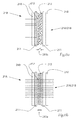
- Fig. 6a and Fig. 6b is the known functional principle of an LC glass or an electrochromic cell, shown here by way of example with reference to the LC-glass 21A / 21B shown in the figures.
- Fig. 6a Fig. 21B shows the LC glass 21A / 21B in its opaque state 21B (current off, reference numeral 215b), whereas Fig. 6b shows the LC glass in its translucent state 21A with voltage applied (current on, reference numeral 215a).
- the LC glass 21A / 21B is made of a polymer liquid crystal film 212 having liquid crystals 213 dissolved therein.
- the polymer liquid crystal film 212 is sandwiched between two conductive layers 211, for example, indium tin oxide (ITO) layers. This construct is in turn embedded between two coverslips 210.
- ITO indium tin oxide
- the dissolved liquid crystals 213 arbitrarily arranged in the electroless state in the polymer liquid crystal film 212 align in a preferred direction, and the LC glass 21A / 21B assumes its transparent state (FIG. Fig. 6b ).
- the voltage is removed, the dissolved liquid crystals return to their disordered state and the LC glass 21A / 21B becomes opaque again (FIG. Fig. 6a ).
- Fig. 7 shows by way of example the layer structure of a multilayer partially transparent layer 22 formed on a supporting substrate 21A / 21B, 24 (see LC glass 21A / 21B according to FIGS. 2 and 3 or the intermediate element 24 according to 4 and 5 ) is applied.
- the layer 22 has a threefold layer structure of a first metal oxide material 22A (eg SiO 2 ) and a second metal oxide material 22B (eg TiO 2 ).
- the surface of the carrier substrate 21A / 21B, 24 is vapor-deposited with metal oxides (high and low-refractive index metal oxides) in a manner known per se.
- Multilayer metal oxide layers and methods for applying such metal oxide layers are described, for example, in US Pat WO 2001/042821 A1 and the EP 2 492 251 A1 described.
- Common materials include MgF 2 (magnesium fluoride), SiO 2 (silicon dioxide), HfO 2 (hafnium dioxide), TiO 2 (titanium dioxide), Ta 2 O 5 (tantalum pentoxide) and Nb 2 O 5 (niobium pentoxide).
- Fig. 8a shows the transmission and absorption behavior of light (Fresnel formulas) on a transparent pane 210, in the example a transparent glass substrate 210.
- the percentages indicated correspond to meaningful and not restrictive reference values.
- Fig. 8b shows the transmission and absorption behavior of light (Fresnel formulas) on the transparent pane 210 when it is additionally coated with an antireflection coating 25 at an interface.
- the AR coating 25 reduces the reflection at the interface and increases the transmittance of the disk 210 (94%).
- Partially translucent mirror reflectance ⁇ 70%
- Electrochromic Covering Element / LC Glass Transmittance ⁇ 75%
- Partially translucent layer reflectance ⁇ 10%
- Electrochromic Covering Element / LC Glass Transmittance ⁇ 75%
- Partially translucent layer reflectance - 10%
- the exemplary comparison shows that the transmittance can be increased by the invention of ⁇ 26% (prior art, only partially translucent mirror) to ⁇ 60-70%.
Landscapes
- Engineering & Computer Science (AREA)
- General Engineering & Computer Science (AREA)
- Chemical & Material Sciences (AREA)
- Crystallography & Structural Chemistry (AREA)
- Mechanical Engineering (AREA)
- Non-Portable Lighting Devices Or Systems Thereof (AREA)
Applications Claiming Priority (1)
| Application Number | Priority Date | Filing Date | Title |
|---|---|---|---|
| ATA50528/2014A AT516080B1 (de) | 2014-07-28 | 2014-07-28 | Abdeckung für eine Leuchteneinrichtung |
Publications (2)
| Publication Number | Publication Date |
|---|---|
| EP2979926A1 true EP2979926A1 (fr) | 2016-02-03 |
| EP2979926B1 EP2979926B1 (fr) | 2019-08-28 |
Family
ID=54035101
Family Applications (1)
| Application Number | Title | Priority Date | Filing Date |
|---|---|---|---|
| EP15175785.3A Active EP2979926B1 (fr) | 2014-07-28 | 2015-07-08 | Feu du véhicule |
Country Status (3)
| Country | Link |
|---|---|
| EP (1) | EP2979926B1 (fr) |
| CN (1) | CN105318248A (fr) |
| AT (1) | AT516080B1 (fr) |
Cited By (4)
| Publication number | Priority date | Publication date | Assignee | Title |
|---|---|---|---|---|
| EP3421875A1 (fr) * | 2017-06-29 | 2019-01-02 | Valeo Vision | Module lumineux comportant un element optique de correction de champ |
| WO2019038141A1 (fr) * | 2017-08-22 | 2019-02-28 | Audi Ag | Projecteur de véhicule automobile ainsi que procédé permettant de faire fonctionner un projecteur |
| WO2020232544A1 (fr) * | 2019-05-22 | 2020-11-26 | Magna Closures Inc. | Phares de véhicule à haut rendement |
| US10899272B2 (en) | 2018-05-29 | 2021-01-26 | Valeo North America, Inc. | Vehicle light with dual projection film |
Families Citing this family (7)
| Publication number | Priority date | Publication date | Assignee | Title |
|---|---|---|---|---|
| CN108267877A (zh) * | 2016-12-30 | 2018-07-10 | 徐煜 | 液晶式智能化遮光装置 |
| JP6998202B2 (ja) * | 2017-12-28 | 2022-02-04 | 株式会社小糸製作所 | 灯具 |
| CN108758553A (zh) * | 2018-07-04 | 2018-11-06 | 天津工业大学 | 快速响应的电控光束挡板 |
| CN109340698A (zh) * | 2018-11-21 | 2019-02-15 | 华域视觉科技(上海)有限公司 | 可替换点灯图案的照明装置及汽车 |
| CN109764308A (zh) * | 2019-02-25 | 2019-05-17 | 华域视觉科技(上海)有限公司 | 转向灯流水效果实现方法和流水转向灯 |
| CN114353008A (zh) * | 2021-12-06 | 2022-04-15 | 上汽大众汽车有限公司 | 一种用于车辆的具有复合涂层的模组透镜、车灯及车辆 |
| US11927319B1 (en) | 2023-04-28 | 2024-03-12 | Ford Global Technologies, Llc | Vehicle lighting system including lamp assembly with one or more sections having variable light transmissivity |
Citations (18)
| Publication number | Priority date | Publication date | Assignee | Title |
|---|---|---|---|---|
| DE8812322U1 (fr) | 1988-09-29 | 1988-12-08 | Rohrer, Emil, 8901 Koenigsbrunn, De | |
| FR2605086B1 (fr) | 1986-10-10 | 1991-03-15 | Cibie Projecteurs | Dispositifs d'eclairage a ecran electrochromique, notamment pour vehicules automobiles |
| DE9302516U1 (fr) | 1993-02-22 | 1993-07-08 | Reiche, Jens-Marko, Dipl.-Ing., O-6305 Gehren, De | |
| DE19704426A1 (de) * | 1997-02-06 | 1998-08-13 | Bosch Gmbh Robert | Scheinwerfer für Fahrzeuge nach dem Projektionsprinzip |
| DE20018807U1 (de) | 2000-11-03 | 2001-04-05 | Oezsoy Hakan | Reflektor für Straßenfahrzeuge |
| WO2001042821A1 (fr) | 1999-12-09 | 2001-06-14 | Femtolasers Produktions Gmbh | Miroir a plusieurs couches |
| DE10233719A1 (de) * | 2002-07-24 | 2004-02-05 | Bayerische Motoren Werke Ag | Leuchte für Kraftfahrzeuge |
| EP1027397B1 (fr) | 1997-07-07 | 2006-10-18 | Bayer Innovation GmbH | Systemes polymeres electrochromes |
| DE10261648B4 (de) | 2002-12-23 | 2008-01-31 | Herner Glas Bernd Hoffbauer Gmbh & Co Leuchten Und Industrieglas Kg | Leuchte |
| WO2008072194A1 (fr) * | 2006-12-15 | 2008-06-19 | Koninklijke Philips Electronics N.V. | Dispositif d'éclairage et dispositif de luminothérapie associé |
| DE202008011128U1 (de) | 2008-08-21 | 2010-01-07 | Rehau Ag + Co | Abdeckvorrichtung für ein Leuchtmittel |
| FR2927858B1 (fr) | 2008-02-26 | 2010-06-04 | Peugeot Citroen Automobiles Sa | Projecteur d'eclairage, a occultation commandee, pour vehicule automobile. |
| DE102009009725A1 (de) * | 2009-02-19 | 2010-08-26 | Dr. Ing. H.C. F. Porsche Aktiengesellschaft | Leuchteinheit |
| KR20110084785A (ko) * | 2010-01-18 | 2011-07-26 | 현대모비스 주식회사 | 헤드램프장치 |
| FR2965889A1 (fr) | 2010-10-12 | 2012-04-13 | Valeo Vision | Glace de dispositif d'eclairage et/ou de signalisation a coefficient de transmission lumineuse variable |
| EP2492251A1 (fr) | 2011-02-23 | 2012-08-29 | Schott Ag | Substrat doté d'un revêtement anti-réfléchissant et son procédé de fabrication |
| US8256940B2 (en) | 2009-09-16 | 2012-09-04 | Control Solutions LLC | Securable cover with electrically activatable light inhibiting lens for vehicle lights |
| JP2013073691A (ja) * | 2011-09-26 | 2013-04-22 | Koito Mfg Co Ltd | 車両用灯具 |
Family Cites Families (7)
| Publication number | Priority date | Publication date | Assignee | Title |
|---|---|---|---|---|
| GB1451066A (en) * | 1973-02-14 | 1976-09-29 | Ass Eng Ltd | Lighting units |
| US4623222A (en) * | 1983-11-14 | 1986-11-18 | Nippondenso Co., Ltd. | Liquid crystal type dazzle-free transmissive-reflective mirror |
| IT1237274B (it) * | 1989-11-17 | 1993-05-27 | Carello Spa | Gruppo di illuminazione per veicoli, in particolare autoveicoli |
| US7009751B2 (en) * | 1999-05-14 | 2006-03-07 | Gentex Corporation | Electrochromic rearview mirror incorporating a third surface partially transmissive reflector |
| DE102008008484B4 (de) * | 2008-02-08 | 2022-01-20 | Volkswagen Ag | Verfahren zum Steuern einer Scheinwerferanordnung |
| JP5448615B2 (ja) * | 2009-07-14 | 2014-03-19 | 株式会社小糸製作所 | 車両用前照灯 |
| US8200390B2 (en) * | 2009-07-30 | 2012-06-12 | Control Solutions LLC | Securable cover for vehicle lights |
-
2014
- 2014-07-28 AT ATA50528/2014A patent/AT516080B1/de not_active IP Right Cessation
-
2015
- 2015-07-08 EP EP15175785.3A patent/EP2979926B1/fr active Active
- 2015-07-28 CN CN201510452223.6A patent/CN105318248A/zh active Pending
Patent Citations (18)
| Publication number | Priority date | Publication date | Assignee | Title |
|---|---|---|---|---|
| FR2605086B1 (fr) | 1986-10-10 | 1991-03-15 | Cibie Projecteurs | Dispositifs d'eclairage a ecran electrochromique, notamment pour vehicules automobiles |
| DE8812322U1 (fr) | 1988-09-29 | 1988-12-08 | Rohrer, Emil, 8901 Koenigsbrunn, De | |
| DE9302516U1 (fr) | 1993-02-22 | 1993-07-08 | Reiche, Jens-Marko, Dipl.-Ing., O-6305 Gehren, De | |
| DE19704426A1 (de) * | 1997-02-06 | 1998-08-13 | Bosch Gmbh Robert | Scheinwerfer für Fahrzeuge nach dem Projektionsprinzip |
| EP1027397B1 (fr) | 1997-07-07 | 2006-10-18 | Bayer Innovation GmbH | Systemes polymeres electrochromes |
| WO2001042821A1 (fr) | 1999-12-09 | 2001-06-14 | Femtolasers Produktions Gmbh | Miroir a plusieurs couches |
| DE20018807U1 (de) | 2000-11-03 | 2001-04-05 | Oezsoy Hakan | Reflektor für Straßenfahrzeuge |
| DE10233719A1 (de) * | 2002-07-24 | 2004-02-05 | Bayerische Motoren Werke Ag | Leuchte für Kraftfahrzeuge |
| DE10261648B4 (de) | 2002-12-23 | 2008-01-31 | Herner Glas Bernd Hoffbauer Gmbh & Co Leuchten Und Industrieglas Kg | Leuchte |
| WO2008072194A1 (fr) * | 2006-12-15 | 2008-06-19 | Koninklijke Philips Electronics N.V. | Dispositif d'éclairage et dispositif de luminothérapie associé |
| FR2927858B1 (fr) | 2008-02-26 | 2010-06-04 | Peugeot Citroen Automobiles Sa | Projecteur d'eclairage, a occultation commandee, pour vehicule automobile. |
| DE202008011128U1 (de) | 2008-08-21 | 2010-01-07 | Rehau Ag + Co | Abdeckvorrichtung für ein Leuchtmittel |
| DE102009009725A1 (de) * | 2009-02-19 | 2010-08-26 | Dr. Ing. H.C. F. Porsche Aktiengesellschaft | Leuchteinheit |
| US8256940B2 (en) | 2009-09-16 | 2012-09-04 | Control Solutions LLC | Securable cover with electrically activatable light inhibiting lens for vehicle lights |
| KR20110084785A (ko) * | 2010-01-18 | 2011-07-26 | 현대모비스 주식회사 | 헤드램프장치 |
| FR2965889A1 (fr) | 2010-10-12 | 2012-04-13 | Valeo Vision | Glace de dispositif d'eclairage et/ou de signalisation a coefficient de transmission lumineuse variable |
| EP2492251A1 (fr) | 2011-02-23 | 2012-08-29 | Schott Ag | Substrat doté d'un revêtement anti-réfléchissant et son procédé de fabrication |
| JP2013073691A (ja) * | 2011-09-26 | 2013-04-22 | Koito Mfg Co Ltd | 車両用灯具 |
Non-Patent Citations (2)
| Title |
|---|
| BLÄSI ET AL.: "Entspiegeln mit Mottenaugenstrukturen", KUNSTSTOFFE, vol. 92, 2002, pages 5 |
| MILLER F.: "Nanostructured surfaces", FRAUNHOFER MAGAZINE, vol. 2, 2005, pages 8 - 12 |
Cited By (9)
| Publication number | Priority date | Publication date | Assignee | Title |
|---|---|---|---|---|
| EP3421875A1 (fr) * | 2017-06-29 | 2019-01-02 | Valeo Vision | Module lumineux comportant un element optique de correction de champ |
| US20190003674A1 (en) * | 2017-06-29 | 2019-01-03 | Valeo Vision | Luminous module including a field-correcting optical element |
| FR3068435A1 (fr) * | 2017-06-29 | 2019-01-04 | Valeo Vision | Module lumineux comportant un element optique de correction de champ |
| US10823357B2 (en) | 2017-06-29 | 2020-11-03 | Valeo Vision | Luminous module including a field-correcting optical element |
| WO2019038141A1 (fr) * | 2017-08-22 | 2019-02-28 | Audi Ag | Projecteur de véhicule automobile ainsi que procédé permettant de faire fonctionner un projecteur |
| CN111051767A (zh) * | 2017-08-22 | 2020-04-21 | 奥迪股份公司 | 用于机动车的前照灯以及用于运行前照灯的方法 |
| US10899272B2 (en) | 2018-05-29 | 2021-01-26 | Valeo North America, Inc. | Vehicle light with dual projection film |
| US11420552B2 (en) | 2018-05-29 | 2022-08-23 | Valeo North America, Inc. | Vehicle light with dual projection film |
| WO2020232544A1 (fr) * | 2019-05-22 | 2020-11-26 | Magna Closures Inc. | Phares de véhicule à haut rendement |
Also Published As
| Publication number | Publication date |
|---|---|
| CN105318248A (zh) | 2016-02-10 |
| EP2979926B1 (fr) | 2019-08-28 |
| AT516080B1 (de) | 2016-04-15 |
| AT516080A1 (de) | 2016-02-15 |
Similar Documents
| Publication | Publication Date | Title |
|---|---|---|
| EP2979926B1 (fr) | Feu du véhicule | |
| EP3391105B1 (fr) | Verre de lunettes comportant un revêtement | |
| DE3731501A1 (de) | Vielschichtiger rueckseitig reflektierender spiegel | |
| DE202017107616U1 (de) | Linienförmige Lichtquelle | |
| EP1523431A1 (fr) | Feu pour vehicules automobiles | |
| DE102009023743A1 (de) | Fahrzeug-Frontscheinwerfer mit der Möglichkeit, die Lichtintensität eines Dunkelbereichs auszugleichen | |
| WO2020043791A1 (fr) | Système d'affichage tête haute | |
| EP4229477A1 (fr) | Élément optique et procédé de fabrication | |
| DE102020008062A1 (de) | Optisches Element mit variabler Transmission, zugehöriges Verfahren und Bildschirm mit einem solchen optischen Element | |
| WO2003071079A1 (fr) | Dispositif pour guider la lumiere | |
| DE202017106313U1 (de) | Optikelement mit wellenlängenselektiver Beschichtung und hiermit ausgestattete Fahrzeugleuchte | |
| DE102015111378B4 (de) | Linsensystem und Verfahren zum Beseitigen von thermischen Effekten durch Sonnenfokussierung in Lampen | |
| EP1935386A1 (fr) | Filtre pare-soleil actif | |
| DE102011002260A1 (de) | Adaptive Beleuchtungsvorrichtung | |
| DE102019206025A1 (de) | Holografisches Anzeigeelement, Vorrichtung zur Anzeige holografischer Darstellungen, Verfahren zur Herstellung eines holografisch optischen Elements sowie Verwendung eines holografischen Anzeigeelements | |
| DE102005004637B4 (de) | Scheinwerfer oder Leuchte, insbesondere für Kraftfahrzeuge, und Verfahren zur Herstellung einer Blenden-Reflektor-Kombination | |
| EP1224419B1 (fr) | Phare pour vehicule automobile | |
| EP1118973A2 (fr) | Protecteur antiréfléchissant pour les feux de signalisation | |
| DE102010050955A1 (de) | Beleuchtungsvorrichtung für Fahrzeuge | |
| AT519123B1 (de) | Kraftfahrzeugscheinwerfer mit zumindest einer Lichtquelle | |
| DE202016103426U1 (de) | Kraftfahrzeugscheinwerfer | |
| DE102023002047A1 (de) | Blendschutz-Rückspiegel und Fahrzeug | |
| WO2023198489A1 (fr) | Ensemble de projection comprenant une vitre feuilletée | |
| WO2023160956A1 (fr) | Guide d'ondes pour l'affichage d'une image et dispositif d'affichage holographique comportant ce guide d'ondes | |
| DE10107017A1 (de) | Leuchte mit einem Leuchtengehäuse |
Legal Events
| Date | Code | Title | Description |
|---|---|---|---|
| PUAI | Public reference made under article 153(3) epc to a published international application that has entered the european phase |
Free format text: ORIGINAL CODE: 0009012 |
|
| AK | Designated contracting states |
Kind code of ref document: A1 Designated state(s): AL AT BE BG CH CY CZ DE DK EE ES FI FR GB GR HR HU IE IS IT LI LT LU LV MC MK MT NL NO PL PT RO RS SE SI SK SM TR |
|
| AX | Request for extension of the european patent |
Extension state: BA ME |
|
| 17P | Request for examination filed |
Effective date: 20160706 |
|
| RBV | Designated contracting states (corrected) |
Designated state(s): AL AT BE BG CH CY CZ DE DK EE ES FI FR GB GR HR HU IE IS IT LI LT LU LV MC MK MT NL NO PL PT RO RS SE SI SK SM TR |
|
| RAP1 | Party data changed (applicant data changed or rights of an application transferred) |
Owner name: ZKW GROUP GMBH |
|
| REG | Reference to a national code |
Ref country code: DE Ref legal event code: R079 Ref document number: 502015010122 Country of ref document: DE Free format text: PREVIOUS MAIN CLASS: B60Q0003020000 Ipc: F21S0041640000 |
|
| GRAP | Despatch of communication of intention to grant a patent |
Free format text: ORIGINAL CODE: EPIDOSNIGR1 |
|
| STAA | Information on the status of an ep patent application or granted ep patent |
Free format text: STATUS: GRANT OF PATENT IS INTENDED |
|
| RIC1 | Information provided on ipc code assigned before grant |
Ipc: F21S 41/20 20180101ALI20180914BHEP Ipc: F21S 41/43 20180101ALI20180914BHEP Ipc: F21S 43/50 20180101ALI20180914BHEP Ipc: F21S 41/25 20180101ALI20180914BHEP Ipc: F21S 43/20 20180101ALI20180914BHEP Ipc: F21S 41/64 20180101AFI20180914BHEP Ipc: F21S 41/50 20180101ALI20180914BHEP Ipc: B60Q 3/74 20170101ALI20180914BHEP |
|
| INTG | Intention to grant announced |
Effective date: 20181023 |
|
| GRAJ | Information related to disapproval of communication of intention to grant by the applicant or resumption of examination proceedings by the epo deleted |
Free format text: ORIGINAL CODE: EPIDOSDIGR1 |
|
| STAA | Information on the status of an ep patent application or granted ep patent |
Free format text: STATUS: REQUEST FOR EXAMINATION WAS MADE |
|
| RIC1 | Information provided on ipc code assigned before grant |
Ipc: F21S 41/64 20180101AFI20180914BHEP Ipc: F21S 43/20 20180101ALI20180914BHEP Ipc: F21S 41/50 20180101ALI20180914BHEP Ipc: F21S 43/50 20180101ALI20180914BHEP Ipc: F21S 41/25 20180101ALI20180914BHEP Ipc: B60Q 3/74 20170101ALI20180914BHEP Ipc: F21S 41/20 20180101ALI20180914BHEP Ipc: F21S 41/43 20180101ALI20180914BHEP |
|
| INTC | Intention to grant announced (deleted) | ||
| GRAP | Despatch of communication of intention to grant a patent |
Free format text: ORIGINAL CODE: EPIDOSNIGR1 |
|
| STAA | Information on the status of an ep patent application or granted ep patent |
Free format text: STATUS: GRANT OF PATENT IS INTENDED |
|
| INTG | Intention to grant announced |
Effective date: 20190319 |
|
| GRAS | Grant fee paid |
Free format text: ORIGINAL CODE: EPIDOSNIGR3 |
|
| GRAA | (expected) grant |
Free format text: ORIGINAL CODE: 0009210 |
|
| STAA | Information on the status of an ep patent application or granted ep patent |
Free format text: STATUS: THE PATENT HAS BEEN GRANTED |
|
| AK | Designated contracting states |
Kind code of ref document: B1 Designated state(s): AL AT BE BG CH CY CZ DE DK EE ES FI FR GB GR HR HU IE IS IT LI LT LU LV MC MK MT NL NO PL PT RO RS SE SI SK SM TR |
|
| REG | Reference to a national code |
Ref country code: GB Ref legal event code: FG4D Free format text: NOT ENGLISH |
|
| REG | Reference to a national code |
Ref country code: CH Ref legal event code: EP |
|
| REG | Reference to a national code |
Ref country code: AT Ref legal event code: REF Ref document number: 1172851 Country of ref document: AT Kind code of ref document: T Effective date: 20190915 |
|
| REG | Reference to a national code |
Ref country code: IE Ref legal event code: FG4D Free format text: LANGUAGE OF EP DOCUMENT: GERMAN |
|
| REG | Reference to a national code |
Ref country code: DE Ref legal event code: R096 Ref document number: 502015010122 Country of ref document: DE |
|
| REG | Reference to a national code |
Ref country code: NL Ref legal event code: MP Effective date: 20190828 |
|
| REG | Reference to a national code |
Ref country code: LT Ref legal event code: MG4D |
|
| PG25 | Lapsed in a contracting state [announced via postgrant information from national office to epo] |
Ref country code: FI Free format text: LAPSE BECAUSE OF FAILURE TO SUBMIT A TRANSLATION OF THE DESCRIPTION OR TO PAY THE FEE WITHIN THE PRESCRIBED TIME-LIMIT Effective date: 20190828 Ref country code: PT Free format text: LAPSE BECAUSE OF FAILURE TO SUBMIT A TRANSLATION OF THE DESCRIPTION OR TO PAY THE FEE WITHIN THE PRESCRIBED TIME-LIMIT Effective date: 20191230 Ref country code: NO Free format text: LAPSE BECAUSE OF FAILURE TO SUBMIT A TRANSLATION OF THE DESCRIPTION OR TO PAY THE FEE WITHIN THE PRESCRIBED TIME-LIMIT Effective date: 20191128 Ref country code: SE Free format text: LAPSE BECAUSE OF FAILURE TO SUBMIT A TRANSLATION OF THE DESCRIPTION OR TO PAY THE FEE WITHIN THE PRESCRIBED TIME-LIMIT Effective date: 20190828 Ref country code: HR Free format text: LAPSE BECAUSE OF FAILURE TO SUBMIT A TRANSLATION OF THE DESCRIPTION OR TO PAY THE FEE WITHIN THE PRESCRIBED TIME-LIMIT Effective date: 20190828 Ref country code: NL Free format text: LAPSE BECAUSE OF FAILURE TO SUBMIT A TRANSLATION OF THE DESCRIPTION OR TO PAY THE FEE WITHIN THE PRESCRIBED TIME-LIMIT Effective date: 20190828 Ref country code: BG Free format text: LAPSE BECAUSE OF FAILURE TO SUBMIT A TRANSLATION OF THE DESCRIPTION OR TO PAY THE FEE WITHIN THE PRESCRIBED TIME-LIMIT Effective date: 20191128 Ref country code: LT Free format text: LAPSE BECAUSE OF FAILURE TO SUBMIT A TRANSLATION OF THE DESCRIPTION OR TO PAY THE FEE WITHIN THE PRESCRIBED TIME-LIMIT Effective date: 20190828 |
|
| PG25 | Lapsed in a contracting state [announced via postgrant information from national office to epo] |
Ref country code: RS Free format text: LAPSE BECAUSE OF FAILURE TO SUBMIT A TRANSLATION OF THE DESCRIPTION OR TO PAY THE FEE WITHIN THE PRESCRIBED TIME-LIMIT Effective date: 20190828 Ref country code: LV Free format text: LAPSE BECAUSE OF FAILURE TO SUBMIT A TRANSLATION OF THE DESCRIPTION OR TO PAY THE FEE WITHIN THE PRESCRIBED TIME-LIMIT Effective date: 20190828 Ref country code: AL Free format text: LAPSE BECAUSE OF FAILURE TO SUBMIT A TRANSLATION OF THE DESCRIPTION OR TO PAY THE FEE WITHIN THE PRESCRIBED TIME-LIMIT Effective date: 20190828 Ref country code: ES Free format text: LAPSE BECAUSE OF FAILURE TO SUBMIT A TRANSLATION OF THE DESCRIPTION OR TO PAY THE FEE WITHIN THE PRESCRIBED TIME-LIMIT Effective date: 20190828 Ref country code: GR Free format text: LAPSE BECAUSE OF FAILURE TO SUBMIT A TRANSLATION OF THE DESCRIPTION OR TO PAY THE FEE WITHIN THE PRESCRIBED TIME-LIMIT Effective date: 20191129 Ref country code: IS Free format text: LAPSE BECAUSE OF FAILURE TO SUBMIT A TRANSLATION OF THE DESCRIPTION OR TO PAY THE FEE WITHIN THE PRESCRIBED TIME-LIMIT Effective date: 20191228 |
|
| PG25 | Lapsed in a contracting state [announced via postgrant information from national office to epo] |
Ref country code: TR Free format text: LAPSE BECAUSE OF FAILURE TO SUBMIT A TRANSLATION OF THE DESCRIPTION OR TO PAY THE FEE WITHIN THE PRESCRIBED TIME-LIMIT Effective date: 20190828 |
|
| PG25 | Lapsed in a contracting state [announced via postgrant information from national office to epo] |
Ref country code: PL Free format text: LAPSE BECAUSE OF FAILURE TO SUBMIT A TRANSLATION OF THE DESCRIPTION OR TO PAY THE FEE WITHIN THE PRESCRIBED TIME-LIMIT Effective date: 20190828 Ref country code: IT Free format text: LAPSE BECAUSE OF FAILURE TO SUBMIT A TRANSLATION OF THE DESCRIPTION OR TO PAY THE FEE WITHIN THE PRESCRIBED TIME-LIMIT Effective date: 20190828 Ref country code: RO Free format text: LAPSE BECAUSE OF FAILURE TO SUBMIT A TRANSLATION OF THE DESCRIPTION OR TO PAY THE FEE WITHIN THE PRESCRIBED TIME-LIMIT Effective date: 20190828 Ref country code: DK Free format text: LAPSE BECAUSE OF FAILURE TO SUBMIT A TRANSLATION OF THE DESCRIPTION OR TO PAY THE FEE WITHIN THE PRESCRIBED TIME-LIMIT Effective date: 20190828 Ref country code: EE Free format text: LAPSE BECAUSE OF FAILURE TO SUBMIT A TRANSLATION OF THE DESCRIPTION OR TO PAY THE FEE WITHIN THE PRESCRIBED TIME-LIMIT Effective date: 20190828 |
|
| PG25 | Lapsed in a contracting state [announced via postgrant information from national office to epo] |
Ref country code: SM Free format text: LAPSE BECAUSE OF FAILURE TO SUBMIT A TRANSLATION OF THE DESCRIPTION OR TO PAY THE FEE WITHIN THE PRESCRIBED TIME-LIMIT Effective date: 20190828 Ref country code: CZ Free format text: LAPSE BECAUSE OF FAILURE TO SUBMIT A TRANSLATION OF THE DESCRIPTION OR TO PAY THE FEE WITHIN THE PRESCRIBED TIME-LIMIT Effective date: 20190828 Ref country code: IS Free format text: LAPSE BECAUSE OF FAILURE TO SUBMIT A TRANSLATION OF THE DESCRIPTION OR TO PAY THE FEE WITHIN THE PRESCRIBED TIME-LIMIT Effective date: 20200224 Ref country code: SK Free format text: LAPSE BECAUSE OF FAILURE TO SUBMIT A TRANSLATION OF THE DESCRIPTION OR TO PAY THE FEE WITHIN THE PRESCRIBED TIME-LIMIT Effective date: 20190828 |
|
| REG | Reference to a national code |
Ref country code: DE Ref legal event code: R097 Ref document number: 502015010122 Country of ref document: DE |
|
| PLBE | No opposition filed within time limit |
Free format text: ORIGINAL CODE: 0009261 |
|
| STAA | Information on the status of an ep patent application or granted ep patent |
Free format text: STATUS: NO OPPOSITION FILED WITHIN TIME LIMIT |
|
| PG2D | Information on lapse in contracting state deleted |
Ref country code: IS |
|
| 26N | No opposition filed |
Effective date: 20200603 |
|
| PG25 | Lapsed in a contracting state [announced via postgrant information from national office to epo] |
Ref country code: SI Free format text: LAPSE BECAUSE OF FAILURE TO SUBMIT A TRANSLATION OF THE DESCRIPTION OR TO PAY THE FEE WITHIN THE PRESCRIBED TIME-LIMIT Effective date: 20190828 |
|
| PG25 | Lapsed in a contracting state [announced via postgrant information from national office to epo] |
Ref country code: MC Free format text: LAPSE BECAUSE OF FAILURE TO SUBMIT A TRANSLATION OF THE DESCRIPTION OR TO PAY THE FEE WITHIN THE PRESCRIBED TIME-LIMIT Effective date: 20190828 |
|
| REG | Reference to a national code |
Ref country code: CH Ref legal event code: PL |
|
| GBPC | Gb: european patent ceased through non-payment of renewal fee |
Effective date: 20200708 |
|
| REG | Reference to a national code |
Ref country code: BE Ref legal event code: MM Effective date: 20200731 |
|
| PG25 | Lapsed in a contracting state [announced via postgrant information from national office to epo] |
Ref country code: LI Free format text: LAPSE BECAUSE OF NON-PAYMENT OF DUE FEES Effective date: 20200731 Ref country code: LU Free format text: LAPSE BECAUSE OF NON-PAYMENT OF DUE FEES Effective date: 20200708 Ref country code: CH Free format text: LAPSE BECAUSE OF NON-PAYMENT OF DUE FEES Effective date: 20200731 Ref country code: GB Free format text: LAPSE BECAUSE OF NON-PAYMENT OF DUE FEES Effective date: 20200708 |
|
| PG25 | Lapsed in a contracting state [announced via postgrant information from national office to epo] |
Ref country code: BE Free format text: LAPSE BECAUSE OF NON-PAYMENT OF DUE FEES Effective date: 20200731 |
|
| PG25 | Lapsed in a contracting state [announced via postgrant information from national office to epo] |
Ref country code: IE Free format text: LAPSE BECAUSE OF NON-PAYMENT OF DUE FEES Effective date: 20200708 |
|
| REG | Reference to a national code |
Ref country code: AT Ref legal event code: MM01 Ref document number: 1172851 Country of ref document: AT Kind code of ref document: T Effective date: 20200708 |
|
| PG25 | Lapsed in a contracting state [announced via postgrant information from national office to epo] |
Ref country code: AT Free format text: LAPSE BECAUSE OF NON-PAYMENT OF DUE FEES Effective date: 20200708 |
|
| PG25 | Lapsed in a contracting state [announced via postgrant information from national office to epo] |
Ref country code: MT Free format text: LAPSE BECAUSE OF FAILURE TO SUBMIT A TRANSLATION OF THE DESCRIPTION OR TO PAY THE FEE WITHIN THE PRESCRIBED TIME-LIMIT Effective date: 20190828 Ref country code: CY Free format text: LAPSE BECAUSE OF FAILURE TO SUBMIT A TRANSLATION OF THE DESCRIPTION OR TO PAY THE FEE WITHIN THE PRESCRIBED TIME-LIMIT Effective date: 20190828 |
|
| PG25 | Lapsed in a contracting state [announced via postgrant information from national office to epo] |
Ref country code: MK Free format text: LAPSE BECAUSE OF FAILURE TO SUBMIT A TRANSLATION OF THE DESCRIPTION OR TO PAY THE FEE WITHIN THE PRESCRIBED TIME-LIMIT Effective date: 20190828 |
|
| P01 | Opt-out of the competence of the unified patent court (upc) registered |
Effective date: 20230528 |
|
| PGFP | Annual fee paid to national office [announced via postgrant information from national office to epo] |
Ref country code: FR Payment date: 20230726 Year of fee payment: 9 Ref country code: DE Payment date: 20230719 Year of fee payment: 9 |