EP2979926A1 - Cover for a light device - Google Patents
Cover for a light device Download PDFInfo
- Publication number
- EP2979926A1 EP2979926A1 EP15175785.3A EP15175785A EP2979926A1 EP 2979926 A1 EP2979926 A1 EP 2979926A1 EP 15175785 A EP15175785 A EP 15175785A EP 2979926 A1 EP2979926 A1 EP 2979926A1
- Authority
- EP
- European Patent Office
- Prior art keywords
- cover
- lighting device
- light
- partially
- motor vehicle
- Prior art date
- Legal status (The legal status is an assumption and is not a legal conclusion. Google has not performed a legal analysis and makes no representation as to the accuracy of the status listed.)
- Granted
Links
- 239000011521 glass Substances 0.000 claims description 52
- 239000004973 liquid crystal related substance Substances 0.000 claims description 44
- 238000000576 coating method Methods 0.000 claims description 36
- 239000011248 coating agent Substances 0.000 claims description 32
- 239000000463 material Substances 0.000 claims description 22
- 229910044991 metal oxide Inorganic materials 0.000 claims description 14
- 150000004706 metal oxides Chemical class 0.000 claims description 14
- 230000003287 optical effect Effects 0.000 claims description 9
- 238000005516 engineering process Methods 0.000 claims description 5
- 238000005286 illumination Methods 0.000 claims 1
- 230000002441 reversible effect Effects 0.000 abstract 1
- 238000002834 transmittance Methods 0.000 description 24
- 239000010408 film Substances 0.000 description 8
- 239000004983 Polymer Dispersed Liquid Crystal Substances 0.000 description 7
- 239000000758 substrate Substances 0.000 description 7
- VYPSYNLAJGMNEJ-UHFFFAOYSA-N Silicium dioxide Chemical compound O=[Si]=O VYPSYNLAJGMNEJ-UHFFFAOYSA-N 0.000 description 6
- GWEVSGVZZGPLCZ-UHFFFAOYSA-N Titan oxide Chemical compound O=[Ti]=O GWEVSGVZZGPLCZ-UHFFFAOYSA-N 0.000 description 6
- 230000005540 biological transmission Effects 0.000 description 6
- 238000009826 distribution Methods 0.000 description 6
- 230000000694 effects Effects 0.000 description 6
- CJNBYAVZURUTKZ-UHFFFAOYSA-N hafnium(iv) oxide Chemical compound O=[Hf]=O CJNBYAVZURUTKZ-UHFFFAOYSA-N 0.000 description 6
- 238000000034 method Methods 0.000 description 6
- 239000005264 High molar mass liquid crystal Substances 0.000 description 5
- 238000010521 absorption reaction Methods 0.000 description 5
- 238000003384 imaging method Methods 0.000 description 5
- 229910004298 SiO 2 Inorganic materials 0.000 description 4
- 229910010413 TiO 2 Inorganic materials 0.000 description 4
- 230000008901 benefit Effects 0.000 description 3
- ORUIBWPALBXDOA-UHFFFAOYSA-L magnesium fluoride Chemical compound [F-].[F-].[Mg+2] ORUIBWPALBXDOA-UHFFFAOYSA-L 0.000 description 3
- 229910001635 magnesium fluoride Inorganic materials 0.000 description 3
- ZKATWMILCYLAPD-UHFFFAOYSA-N niobium pentoxide Inorganic materials O=[Nb](=O)O[Nb](=O)=O ZKATWMILCYLAPD-UHFFFAOYSA-N 0.000 description 3
- URLJKFSTXLNXLG-UHFFFAOYSA-N niobium(5+);oxygen(2-) Chemical compound [O-2].[O-2].[O-2].[O-2].[O-2].[Nb+5].[Nb+5] URLJKFSTXLNXLG-UHFFFAOYSA-N 0.000 description 3
- BPUBBGLMJRNUCC-UHFFFAOYSA-N oxygen(2-);tantalum(5+) Chemical compound [O-2].[O-2].[O-2].[O-2].[O-2].[Ta+5].[Ta+5] BPUBBGLMJRNUCC-UHFFFAOYSA-N 0.000 description 3
- 239000002245 particle Substances 0.000 description 3
- 239000004033 plastic Substances 0.000 description 3
- 229920003023 plastic Polymers 0.000 description 3
- 230000008569 process Effects 0.000 description 3
- 235000012239 silicon dioxide Nutrition 0.000 description 3
- 239000000377 silicon dioxide Substances 0.000 description 3
- PBCFLUZVCVVTBY-UHFFFAOYSA-N tantalum pentoxide Inorganic materials O=[Ta](=O)O[Ta](=O)=O PBCFLUZVCVVTBY-UHFFFAOYSA-N 0.000 description 3
- 239000004408 titanium dioxide Substances 0.000 description 3
- 238000007740 vapor deposition Methods 0.000 description 3
- 239000006059 cover glass Substances 0.000 description 2
- 230000001419 dependent effect Effects 0.000 description 2
- 230000004907 flux Effects 0.000 description 2
- 238000004519 manufacturing process Methods 0.000 description 2
- JKQOBWVOAYFWKG-UHFFFAOYSA-N molybdenum trioxide Chemical compound O=[Mo](=O)=O JKQOBWVOAYFWKG-UHFFFAOYSA-N 0.000 description 2
- 239000002086 nanomaterial Substances 0.000 description 2
- 230000005855 radiation Effects 0.000 description 2
- 238000002310 reflectometry Methods 0.000 description 2
- 230000004044 response Effects 0.000 description 2
- ZNOKGRXACCSDPY-UHFFFAOYSA-N tungsten trioxide Chemical compound O=[W](=O)=O ZNOKGRXACCSDPY-UHFFFAOYSA-N 0.000 description 2
- 229910052724 xenon Inorganic materials 0.000 description 2
- FHNFHKCVQCLJFQ-UHFFFAOYSA-N xenon atom Chemical compound [Xe] FHNFHKCVQCLJFQ-UHFFFAOYSA-N 0.000 description 2
- LBJBPGRQRGLKPL-UHFFFAOYSA-N 7-(4-chlorophenyl)-5-naphthalen-2-yl-6-sulfanylidene-2,3-dihydro-1h-pyrrolo[3,4-e][1,4]diazepin-8-one Chemical compound C1=CC(Cl)=CC=C1N1C(=S)C(C(=NCCN2)C=3C=C4C=CC=CC4=CC=3)=C2C1=O LBJBPGRQRGLKPL-UHFFFAOYSA-N 0.000 description 1
- 101000604957 Homo sapiens Phosducin-like protein Proteins 0.000 description 1
- 102100038218 Phosducin-like protein Human genes 0.000 description 1
- 229920001609 Poly(3,4-ethylenedioxythiophene) Polymers 0.000 description 1
- 230000008859 change Effects 0.000 description 1
- 238000005229 chemical vapour deposition Methods 0.000 description 1
- 238000010276 construction Methods 0.000 description 1
- 238000007796 conventional method Methods 0.000 description 1
- 230000007423 decrease Effects 0.000 description 1
- 230000005670 electromagnetic radiation Effects 0.000 description 1
- 238000002474 experimental method Methods 0.000 description 1
- 229940073322 ferric hexacyanoferrate Drugs 0.000 description 1
- 230000004313 glare Effects 0.000 description 1
- 229910052736 halogen Inorganic materials 0.000 description 1
- 150000002367 halogens Chemical class 0.000 description 1
- AMGQUBHHOARCQH-UHFFFAOYSA-N indium;oxotin Chemical compound [In].[Sn]=O AMGQUBHHOARCQH-UHFFFAOYSA-N 0.000 description 1
- 238000009434 installation Methods 0.000 description 1
- 210000000554 iris Anatomy 0.000 description 1
- DCYOBGZUOMKFPA-UHFFFAOYSA-N iron(2+);iron(3+);octadecacyanide Chemical compound [Fe+2].[Fe+2].[Fe+2].[Fe+3].[Fe+3].[Fe+3].[Fe+3].N#[C-].N#[C-].N#[C-].N#[C-].N#[C-].N#[C-].N#[C-].N#[C-].N#[C-].N#[C-].N#[C-].N#[C-].N#[C-].N#[C-].N#[C-].N#[C-].N#[C-].N#[C-] DCYOBGZUOMKFPA-UHFFFAOYSA-N 0.000 description 1
- 230000000873 masking effect Effects 0.000 description 1
- 239000000203 mixture Substances 0.000 description 1
- 229910000480 nickel oxide Inorganic materials 0.000 description 1
- QGLKJKCYBOYXKC-UHFFFAOYSA-N nonaoxidotritungsten Chemical compound O=[W]1(=O)O[W](=O)(=O)O[W](=O)(=O)O1 QGLKJKCYBOYXKC-UHFFFAOYSA-N 0.000 description 1
- NJPPVKZQTLUDBO-UHFFFAOYSA-N novaluron Chemical compound C1=C(Cl)C(OC(F)(F)C(OC(F)(F)F)F)=CC=C1NC(=O)NC(=O)C1=C(F)C=CC=C1F NJPPVKZQTLUDBO-UHFFFAOYSA-N 0.000 description 1
- 239000013307 optical fiber Substances 0.000 description 1
- GNRSAWUEBMWBQH-UHFFFAOYSA-N oxonickel Chemical compound [Ni]=O GNRSAWUEBMWBQH-UHFFFAOYSA-N 0.000 description 1
- 229920000767 polyaniline Polymers 0.000 description 1
- 229920000642 polymer Polymers 0.000 description 1
- 239000002861 polymer material Substances 0.000 description 1
- 238000002360 preparation method Methods 0.000 description 1
- 230000001012 protector Effects 0.000 description 1
- 229960003351 prussian blue Drugs 0.000 description 1
- 239000013225 prussian blue Substances 0.000 description 1
- 230000009467 reduction Effects 0.000 description 1
- 230000011664 signaling Effects 0.000 description 1
- 239000010409 thin film Substances 0.000 description 1
- 230000007704 transition Effects 0.000 description 1
- 229910001930 tungsten oxide Inorganic materials 0.000 description 1
Images


Classifications
-
- B—PERFORMING OPERATIONS; TRANSPORTING
- B60—VEHICLES IN GENERAL
- B60Q—ARRANGEMENT OF SIGNALLING OR LIGHTING DEVICES, THE MOUNTING OR SUPPORTING THEREOF OR CIRCUITS THEREFOR, FOR VEHICLES IN GENERAL
- B60Q3/00—Arrangement of lighting devices for vehicle interiors; Lighting devices specially adapted for vehicle interiors
- B60Q3/70—Arrangement of lighting devices for vehicle interiors; Lighting devices specially adapted for vehicle interiors characterised by the purpose
- B60Q3/74—Arrangement of lighting devices for vehicle interiors; Lighting devices specially adapted for vehicle interiors characterised by the purpose for overall compartment lighting; for overall compartment lighting in combination with specific lighting, e.g. room lamps with reading lamps
-
- F—MECHANICAL ENGINEERING; LIGHTING; HEATING; WEAPONS; BLASTING
- F21—LIGHTING
- F21S—NON-PORTABLE LIGHTING DEVICES; SYSTEMS THEREOF; VEHICLE LIGHTING DEVICES SPECIALLY ADAPTED FOR VEHICLE EXTERIORS
- F21S41/00—Illuminating devices specially adapted for vehicle exteriors, e.g. headlamps
- F21S41/20—Illuminating devices specially adapted for vehicle exteriors, e.g. headlamps characterised by refractors, transparent cover plates, light guides or filters
- F21S41/285—Refractors, transparent cover plates, light guides or filters not provided in groups F21S41/24 - F21S41/2805
-
- F—MECHANICAL ENGINEERING; LIGHTING; HEATING; WEAPONS; BLASTING
- F21—LIGHTING
- F21S—NON-PORTABLE LIGHTING DEVICES; SYSTEMS THEREOF; VEHICLE LIGHTING DEVICES SPECIALLY ADAPTED FOR VEHICLE EXTERIORS
- F21S41/00—Illuminating devices specially adapted for vehicle exteriors, e.g. headlamps
- F21S41/40—Illuminating devices specially adapted for vehicle exteriors, e.g. headlamps characterised by screens, non-reflecting members, light-shielding members or fixed shades
- F21S41/43—Illuminating devices specially adapted for vehicle exteriors, e.g. headlamps characterised by screens, non-reflecting members, light-shielding members or fixed shades characterised by the shape thereof
-
- F—MECHANICAL ENGINEERING; LIGHTING; HEATING; WEAPONS; BLASTING
- F21—LIGHTING
- F21S—NON-PORTABLE LIGHTING DEVICES; SYSTEMS THEREOF; VEHICLE LIGHTING DEVICES SPECIALLY ADAPTED FOR VEHICLE EXTERIORS
- F21S41/00—Illuminating devices specially adapted for vehicle exteriors, e.g. headlamps
- F21S41/50—Illuminating devices specially adapted for vehicle exteriors, e.g. headlamps characterised by aesthetic components not otherwise provided for, e.g. decorative trim, partition walls or covers
-
- F—MECHANICAL ENGINEERING; LIGHTING; HEATING; WEAPONS; BLASTING
- F21—LIGHTING
- F21S—NON-PORTABLE LIGHTING DEVICES; SYSTEMS THEREOF; VEHICLE LIGHTING DEVICES SPECIALLY ADAPTED FOR VEHICLE EXTERIORS
- F21S41/00—Illuminating devices specially adapted for vehicle exteriors, e.g. headlamps
- F21S41/60—Illuminating devices specially adapted for vehicle exteriors, e.g. headlamps characterised by a variable light distribution
- F21S41/63—Illuminating devices specially adapted for vehicle exteriors, e.g. headlamps characterised by a variable light distribution by acting on refractors, filters or transparent cover plates
- F21S41/64—Illuminating devices specially adapted for vehicle exteriors, e.g. headlamps characterised by a variable light distribution by acting on refractors, filters or transparent cover plates by changing their light transmissivity, e.g. by liquid crystal or electrochromic devices
- F21S41/645—Illuminating devices specially adapted for vehicle exteriors, e.g. headlamps characterised by a variable light distribution by acting on refractors, filters or transparent cover plates by changing their light transmissivity, e.g. by liquid crystal or electrochromic devices by electro-optic means, e.g. liquid crystal or electrochromic devices
-
- F—MECHANICAL ENGINEERING; LIGHTING; HEATING; WEAPONS; BLASTING
- F21—LIGHTING
- F21S—NON-PORTABLE LIGHTING DEVICES; SYSTEMS THEREOF; VEHICLE LIGHTING DEVICES SPECIALLY ADAPTED FOR VEHICLE EXTERIORS
- F21S43/00—Signalling devices specially adapted for vehicle exteriors, e.g. brake lamps, direction indicator lights or reversing lights
- F21S43/20—Signalling devices specially adapted for vehicle exteriors, e.g. brake lamps, direction indicator lights or reversing lights characterised by refractors, transparent cover plates, light guides or filters
- F21S43/255—Filters
-
- F—MECHANICAL ENGINEERING; LIGHTING; HEATING; WEAPONS; BLASTING
- F21—LIGHTING
- F21S—NON-PORTABLE LIGHTING DEVICES; SYSTEMS THEREOF; VEHICLE LIGHTING DEVICES SPECIALLY ADAPTED FOR VEHICLE EXTERIORS
- F21S43/00—Signalling devices specially adapted for vehicle exteriors, e.g. brake lamps, direction indicator lights or reversing lights
- F21S43/50—Signalling devices specially adapted for vehicle exteriors, e.g. brake lamps, direction indicator lights or reversing lights characterised by aesthetic components not otherwise provided for, e.g. decorative trim, partition walls or covers
Definitions
- the invention relates to a cover for a lighting device, in particular for a lighting device of a motor vehicle headlight.
- the field of application of the invention is intended especially for use in motor vehicle (motor vehicle) main headlights.
- the invention can also be used for other purposes in the automotive sector, such as a cover in the vehicle taillight area and for lights in the interior of a motor vehicle.
- the invention further relates to lighting devices, in particular lighting devices for motor vehicles, which have a cover according to the invention.
- a partially translucent mirror also referred to as a semi-transmissive mirror, one-way mirror, spy mirror, police mirror or Venetian mirror, as a cover for lights.
- Partially translucent mirrors are well known to a person skilled in the art. This is a translucent component (eg a transparent glass pane), which is mirrored on one side with a thin light-reflecting layer, whereas the other side of the component allows the light to pass through unhindered.
- the effect of the Venetian mirror is based on that it is very bright on the coated side of the disc and very dark on the other side. Due to this difference in brightness, the disc is perceived by the viewer as an opaque mirror and from the dark area as transparent from the bright area.
- the DE 9302516 U1 describes the execution of a light cover as a semitransparent mirror, which is almost opaque and mirrored in the "off” state of the lamp, whereas it loses its mirror property in the "on” state of the lamp and becomes translucent.
- the DE 200 18 807 U1 describes the use of a semitransparent mirror, which prevents the view of a reflector (ie retro-reflector) of a road vehicle in diffuse light incidence, while directed light rays impinge on the reflector and are reflected.
- a semitransparent mirror which prevents the view of a reflector (ie retro-reflector) of a road vehicle in diffuse light incidence, while directed light rays impinge on the reflector and are reflected.
- the DE 20 2008 011 128 U1 discloses a covering device for a light-emitting material lamp comprising a cover element and a layer applied on the surface of the cover element, the visible light layer having a transmittance of at least 0.12 and a reflectance of at least 0.35.
- electrochromic materials such as electrochromic elements and disks or LC-glasses having a polymer liquid-crystal film (also referred to as PDLC glasses) whose transmission properties for light can be changed as a function of an applied electrical voltage.
- Electrochromic materials and LC glasses are well known to those skilled in the art. When opaque, electrochromic materials and LC glasses have a milky opaque appearance and are commonly used in building glazings, panoramic roofs, rear-view mirrors, vehicle glazing and displays, as well as in interior glazings intended to effect privacy.
- liquid crystal panels for the coverage of lighting equipment on motor vehicles is from the DE 8812322 U1 known.
- the FR 2 605 086 B1 discloses the use of electrochromic material layers which, in the opaque (ie opaque) switched state, block the view of a headlight and allow the exit of a headlight beam in the light-transmissively switched state.
- the FR 2 927 858 B1 discloses the use of an electrochromic element as a screen protector on a motor vehicle headlamp.
- a carrier element is subjected to electrochromic material, whereby the passage of light is blocked or allowed in dependence on the desired switching state of the electrochromic material.
- the FR 2 965 889 A1 describes an electrochromic element as a cover to mask the view of a headlamp module by changing the transmittance and thus to change the appearance of the headlamp.
- a cover glass for a headlight is disclosed.
- the cover glass is equipped with an electrochromic film, which allows between a translucent and an opaque state to switch.
- an electrochromic film which allows between a translucent and an opaque state to switch.
- a cover based on an electrochromic material or an LC glass does not have a high-gloss and mirrored appearance (design) and therefore does not correspond to the customer's intention mentioned in the introduction.
- a covering device for a lighting device in particular for a lighting device of a motor vehicle headlight, which is perceived in the cold appearance (ie lighting device or headlights not in operation) as high gloss and at the same time the insight on the underlying lighting technology Prevents elements.
- the impression of coldness in the viewer should give the impression that a high-gloss privacy cover is located in front of the light function and thus blocks the view of the lighting elements of the lighting device.
- the cover should have no relevant influence on the light function of the lighting elements positioned behind the cover in the warm appearance (i.e., lighting device in operation). This means that the light in the warm appearance can illuminate substantially unhindered through the cover / aperture, without larger light losses occur.
- a cover for a lamp device in particular for a lamp device of a motor vehicle headlamp, which according to the invention an electrically activatable cover, which is switchable in response to an applied electrical voltage between at least one transparent state and an opaque state and which has an inner surface and a Having outer surface, and a partially transparent layer comprises.
- an electrically activatable cover eg an electrochromic disk or LC glass according to a known type
- a partially translucent layer as used in a Venetian mirror
- the effect of a Venetian mirror is, as mentioned, all the more pronounced, the greater the difference in brightness between the dark and the bright side of the mirror.
- the electrically activated disk can assume an opaque state, which is why the area facing the lighting device, looks very dark.
- the reflectance of the partially transparent layer can be reduced to a minimum without the effect of a Venetian mirror in the cold appearance, i. a high-gloss mirroring, for the viewer is lost.
- the electrically activatable cover is switched back to light transparent.
- a minimum reflectance of the partially transparent layer has the advantage that in the active operating state of the light modules, the cover according to the invention has a high degree of transmittance.
- the transmittance of the cover according to the invention can be increased to> 60%, which is why the efficiency of the lighting device remains within an acceptable range.
- the luminous flux or the light distribution is only slightly influenced because on the one hand the reflectance of the partially transparent layer is kept very small and on the other hand, the electrically activatable cover in the light-transmitting state has a very high transmittance.
- the invention enables new hitherto unrealizable designs of lighting devices, in particular headlight designs in the off state. Thanks to the invention, the headlight in its cold appearance on a customer request high-gloss appearance, which does not or only slightly affect the warm-up operation of the headlamp. Furthermore, there is the possibility of headlamps not only in the cold, but also in daytime running the Hide main light functions behind an optically active shutter.
- Behind the cover according to the invention can not vorzuborgen only technically relevant components such as reflectors, lenses, light sticks, etc., but the aperture can also be used at the same time to other relevant in the body construction constructive configurations such as gap dimensions, pivoting joints ( ie clearance between fixed and movable panels of eg curve light modules) to cover.
- the cover according to the invention also has the advantage, due to its high-gloss appearance in the cold appearance, that expensive high-quality design screens can be saved.
- luminaire device also referred to herein as a luminaire, refers to a combination of a luminous means with components which influence the electromagnetic radiation radiated by the luminous means and project a desired illuminance distribution (eg, law-compliant low beam light) in front of the motor vehicle including vehicle headlamps is well known and may vary depending on the type and use of the lighting device
- the lighting device can, for example, projection system (light source, reflector assembly, refractive optical elements with / without diaphragms), reflection systems (light source, reflector), imaging systems (light source, attachment optics , with / without additional imaging lens systems), light guides, luminous plates, OLED elements, and any other lighting components known to those skilled in the art n (HID), LEDs, laser light sources, and the like.
- projection system light source, reflector assembly, refractive optical elements with / without diaphragms
- reflection systems light source, reflector
- imaging systems light source, attachment optics , with / without additional imaging lens systems
- the cover according to the invention is used in lighting fixtures for motor vehicles (motor vehicles), in particular in headlights, and is suitable for any arbitrarily configured pig headlight module.
- the field of application of the invention is particularly advantageous for use in automotive headlamps.
- the invention can also be used for other purposes in the automotive sector, such as a cover in the vehicle taillight area and for lights in the interior of a motor vehicle.
- the invention is particularly advantageous for the automotive sector, it can be useful in all areas where on the one hand the external appearance (design) of a lighting device for an observer is an important feature and on the other hand an influence of the light or the light distribution must be kept as low as possible (especially high transmittance).
- the transmittance may be defined by the degree of transmittance ⁇ .
- the terms "translucent”, “translucent” and “translucent” mean that the electrically activatable visible light masking element is passable, and for the functionality of headlamps, it is essential for the covers located downstream of a lamp unit in the optical beam direction
- the efficiency for the light emission the physical measure of which is the luminous flux.
- realistic values are 30-40%, reflection applications reach up to 60 These values result from the losses in the system (reflectivity of the reflector surface, absorption losses in the lens and the lens) and a geometric degree of utilization, which depends on the available installation space, the emission characteristics of the light source and the design strategy of the Lichttec hnikers depends. If you want to hide a projection module behind a cover according to the invention and reach acceptable operating efficiency of the headlamp, the degree of transmission of the cover is preferably about 50%.
- the “inner surface of the cover member” is that surface of the cover member that faces the lamp apparatus.
- the “outer surface of the cover element” is understood to mean the surface of the cover element which faces away from the luminaire device.
- headlamp includes all types of automotive headlamps, particularly headlamps and taillights.
- partially translucent layer or “partially translucent coating” means a reflective layer or coating of the type used in disposable mirrors (Venetian mirror, spy mirror). Such layers are known to the person skilled in the art.
- the term “coldness” refers to the fact that the lighting device or the headlight is not in operation.
- the term “warm appearance” refers to the fact that the lighting device or the headlight is in operation and radiates law-compliant light distribution.
- the partially transparent visible light layer has a reflectance of 10% to 40%.
- the cover according to the invention has a high degree of transmission for visible light. This is of great relevance, above all, for the motor vehicle headlight sector.
- the partially transparent visible light layer has a reflectance of 10% to 25%.
- the partially transparent film is preferably made of a metal oxide material.
- the surface is vapor-deposited with metal oxides (high and low-refractive index metal oxides) in a manner known per se, wherein a sequence of thin layers with different refractive index is applied until an overall layer having a desired reflectance is achieved.
- the reflectance can also be carried out depending on the wavelength, so that the coatings can be used in addition to the increase in efficiency for the generation of color impressions - especially in the design of the cold phenomenon.
- Multilayer metal oxide layers and methods for Application of such metal oxide layers are for example in WO 2001/042821 A1 and the EP 2 492 251 A1 described.
- Common materials include MgF 2 (magnesium fluoride), SiO 2 (silicon dioxide), HfO 2 (hafnium dioxide), TiO 2 (titanium dioxide), Ta 2 O 5 (tantalum pentoxide) and Nb 2 O 5 (niobium pentoxide).
- the partially translucent layer is at least partially applied directly on the outer surface of the cover.
- the entire outer surface or only a portion of the outer surface of the cover member may be coated with the partially transparent layer.
- an antireflection coating (AR coating, AR coating) is applied at least in regions on the inner surface of the cover element.
- the reflectance can typically be reduced by about 4% by applying an AR coating on the inner surface of the cover member; the transmittance of the cover is thereby increased.
- the entire inner surface of the cover member is coated with the AR coating.
- Common coating materials include MgF 2 (magnesium fluoride), SiO 2 (silicon dioxide), HfO 2 (hafnium dioxide), TiO 2 (titanium dioxide), Ta 2 O 5 (tantalum pentoxide) and Nb 2 O 5 (niobium pentoxide).
- MgF 2 magnesium fluoride
- SiO 2 silicon dioxide
- HfO 2 hafnium dioxide
- TiO 2 titanium dioxide
- Ta 2 O 5 tantalum pentoxide
- Nb 2 O 5 niobium pentoxide
- the reflection of the light emitted by the luminaire device at the boundary surfaces of the cover element can also be reduced by means of special nanostructures, so-called moth eye structures, applied to the surfaces of the cover element (see, for example, US Pat Bläsi et al .. Deflection with moth eye structures. Plastics 92 (2002) 5 ; Miller F., Nanostructured surfaces, Fraunhofer magazine 2.2005: 8-12 ). These nanostructures are advantageously used on plastic surfaces where vapor deposition with AR coatings is difficult by conventional techniques.
- the cover has a translucent intermediate element (eg a translucent glass or plastic disk) with an inner surface and an outer surface, the inner surface of the intermediate element facing the outer surface of the cover element and the partially translucent layer at least partially covering the outer surface of the outer surface Intermediate element is applied.
- a translucent intermediate element eg a translucent glass or plastic disk
- the inner surface of the intermediate element refers to that surface of the intermediate member facing the lamp apparatus.
- the "outer surface of the intermediate element” means that surface of the intermediate element which faces away from the luminaire device.
- the inner surface of the intermediate element is arranged in direct contact with the outer surface of the cover.
- the inner surface of the intermediate member and the outer surface of the cover are spaced apart.
- the inner surface of the cover is at least partially coated with an AR coating according to the above statements.
- the entire inner surface of the cover member is coated with the AR coating.
- an AR coating may also be applied to the outer surface of the cover element.
- the entire outer surface of the cover member is coated with the AR coating.
- the electrically activatable cover element comprises an electrochromic material.
- cover elements are known to a person skilled in the art under the names “electrochromic glass”, “electrochromic pane” or “electrochromic cell” and are used in a conventional manner in the motor vehicle sector (vehicle glazing, rearview mirrors, headlamp covers) as well as building glazings.
- suitable cover elements in the FR 2 605 086 B21 , of the FR 2 927 858 B1 , of the FR 2 965 889 A1 and the US 8,256,940 B2 described.
- an electrical voltage usually a DC voltage
- electrochromic materials are for example tungsten oxide, Molybdenum trioxide, polyaniline, tungsten trioxide, nickel oxide, ferric hexacyanoferrate (Prussian Blue), 3,4-polyethylenedioxithophene (PEDOT) and 3,4-polyethylenedioxypyrrole (PEDOP). Further suitable for the invention electrochromic polymers are EP10273997 B1 refer to.
- LC liquid crystal
- the electrically activatable cover element therefore comprises an LC glass.
- the heart of the LC lens is a polymer liquid crystal film sandwiched between two conductive disks and connected to a power source.
- LC glasses include polymer dispersed liquid crystals (PDLC) and suspended particle devices (SPD).
- PDLC polymer dispersed liquid crystals
- SPD suspended particle devices
- the LC glass is a PDLC glass or an SPD element, more preferably an SPD element.
- SPD suspended particle devices
- a PDLC glass In a PDCL glass, the liquid crystal molecules align by applying a voltage, and the PDLC glass becomes transparent due to the changed scattering behavior of the liquid crystal molecules. With no applied voltage, a PDLC glass assumes an opaque state (typically milky, opaque appearance). SPD elements comprise dissolved light-absorbing, rod-shaped suspended particles which align themselves due to an applied voltage, so that an SPD glass becomes transparent. In the de-energized state, the suspended particles are stochastically distributed, which is why the SPD element assumes a light-absorbing state.
- An LC glass suitable for the present invention is, for example, in the above DE 8812322 U1 described.
- the electrically activatable cover is in the opaque state when the lighting device is not in operation (cold) or in the translucent state when the lighting device is in operation (warmth).
- Another object of the invention is also the use of the cover according to the invention as an optically activated aperture for automotive lights, in particular as optically activated aperture for motor vehicle headlights.
- the electrically activatable cover member is in the opaque state when the vehicle lamp or the headlamp is not in operation (cold appearance) and in the translucent state when the vehicle lamp or the headlamp is in operation (warm appearance).
- the invention further relates to a lighting device, in particular a lighting device for a motor vehicle, comprising a lighting device according to a known type and as described above and one of the lamp device in the optical beam direction downstream cover according to the invention as described and defined herein.
- the lighting device according to the invention can be used in the entire automotive sector (for example, cars, trucks, motorcycles, etc.).
- the lighting device for a motor vehicle is preferably a motor vehicle headlight.
- the cover is conveniently arranged in the vehicle headlight in the optical beam direction between the lamp device and a lens of the motor vehicle headlight.
- Car headlamps include headlamps (also referred to as headlamps) and tail lights.
- headlamps include headlamps (also referred to as headlamps) and tail lights.
- headlamps also referred to as headlamps
- tail lights Particularly advantageous cover of the invention, however, is used in headlights.
- a further advantageous variant of a lighting device for motor vehicles according to the invention relates to automotive interior lights.
- Fig. 2 shows an arrangement of a lighting device 10 in their warm appearance as described above and an advantageous embodiment of the diaphragm 20 according to the invention, wherein the aperture 20 is switched to translucent in the warm appearance.
- Fig. 3 shows the arrangement Fig. 2 , wherein the lighting device 10 is not in operation (cold phenomenon) and the aperture 20 is therefore opaque.
- cover 20 comprises an LC glass 21A / 21B (alternatively, an electrochromic element), which by means of an electrical voltage between a light-transmitting state 21A (current on; Fig. 2 and Fig. 6b ) and an opaque / opaque state 21B (power off; Fig. 3 and Fig.
- the LC glass 21A / 21B has an inner surface 15 facing the luminaire device and an outer surface 35 facing the viewer 30.
- the layer 22 for the viewer 30 appears as a high-gloss and the lighting elements of the lighting device 10 concealing aperture.
- an antireflection coating 25 is additionally applied to the inner surface 15.
- the AR coating 25 is made by vapor deposition with a metal oxide.
- Fig. 4 shows an arrangement of a lamp device 10 and a further embodiment of the diaphragm 20 according to the invention, wherein the aperture 20 is switched to translucent in the warm appearance.
- Fig. 5 shows the arrangement Fig. 4 , wherein the lighting device 10 is not in operation (cold phenomenon) and the aperture 20 is therefore opaque.
- the aperture 20 comprises an LC glass 21A / 21B (alternatively an electrochromic element), which by means of an electrical voltage between a light-transmitting state 21A (current on; Fig. 2 and Fig. 6b ) and an opaque / opaque state 21B (power off; Fig. 3 and Fig. 6a ) is switchable according to known manner.
- the LC glass 21A / 21B has an inner surface 15 facing the luminaire device and an outer surface 35 facing the viewer 30.
- an antireflection coating 25 (AR coating, AR coating).
- the AR coating 25 is produced by vacuum vapor deposition or coating techniques using CVD processes (Chemical Vapor Deposition) or PVD processes (Physical Vapor Depositio) with eg metal oxides.
- the diaphragm 20 further comprises a transparent intermediate member 24 (disk of glass or a polymer material) having an inner surface 26 and an outer surface 27.
- the intermediate member 24 is the LC glass 21A / 21B downstream in the optical beam direction and spaced therefrom.
- a partially transparent layer 22 applied in a conventional manner (Venetian mirror). In the cold phenomenon ( Fig. 5 ), the layer 22 for the viewer 30 appears as a high-gloss and the lighting elements of the lighting device 10 occluding aperture.
- FIGS. 2 and 3 shown embodiment of the diaphragm 20 according to the invention is due to their simpler structure and greater efficiency over that in the 4 and 5 shown another embodiment preferred.
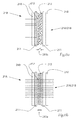
- Fig. 6a and Fig. 6b is the known functional principle of an LC glass or an electrochromic cell, shown here by way of example with reference to the LC-glass 21A / 21B shown in the figures.
- Fig. 6a Fig. 21B shows the LC glass 21A / 21B in its opaque state 21B (current off, reference numeral 215b), whereas Fig. 6b shows the LC glass in its translucent state 21A with voltage applied (current on, reference numeral 215a).
- the LC glass 21A / 21B is made of a polymer liquid crystal film 212 having liquid crystals 213 dissolved therein.
- the polymer liquid crystal film 212 is sandwiched between two conductive layers 211, for example, indium tin oxide (ITO) layers. This construct is in turn embedded between two coverslips 210.
- ITO indium tin oxide
- the dissolved liquid crystals 213 arbitrarily arranged in the electroless state in the polymer liquid crystal film 212 align in a preferred direction, and the LC glass 21A / 21B assumes its transparent state (FIG. Fig. 6b ).
- the voltage is removed, the dissolved liquid crystals return to their disordered state and the LC glass 21A / 21B becomes opaque again (FIG. Fig. 6a ).
- Fig. 7 shows by way of example the layer structure of a multilayer partially transparent layer 22 formed on a supporting substrate 21A / 21B, 24 (see LC glass 21A / 21B according to FIGS. 2 and 3 or the intermediate element 24 according to 4 and 5 ) is applied.
- the layer 22 has a threefold layer structure of a first metal oxide material 22A (eg SiO 2 ) and a second metal oxide material 22B (eg TiO 2 ).
- the surface of the carrier substrate 21A / 21B, 24 is vapor-deposited with metal oxides (high and low-refractive index metal oxides) in a manner known per se.
- Multilayer metal oxide layers and methods for applying such metal oxide layers are described, for example, in US Pat WO 2001/042821 A1 and the EP 2 492 251 A1 described.
- Common materials include MgF 2 (magnesium fluoride), SiO 2 (silicon dioxide), HfO 2 (hafnium dioxide), TiO 2 (titanium dioxide), Ta 2 O 5 (tantalum pentoxide) and Nb 2 O 5 (niobium pentoxide).
- Fig. 8a shows the transmission and absorption behavior of light (Fresnel formulas) on a transparent pane 210, in the example a transparent glass substrate 210.
- the percentages indicated correspond to meaningful and not restrictive reference values.
- Fig. 8b shows the transmission and absorption behavior of light (Fresnel formulas) on the transparent pane 210 when it is additionally coated with an antireflection coating 25 at an interface.
- the AR coating 25 reduces the reflection at the interface and increases the transmittance of the disk 210 (94%).
- Partially translucent mirror reflectance ⁇ 70%
- Electrochromic Covering Element / LC Glass Transmittance ⁇ 75%
- Partially translucent layer reflectance ⁇ 10%
- Electrochromic Covering Element / LC Glass Transmittance ⁇ 75%
- Partially translucent layer reflectance - 10%
- the exemplary comparison shows that the transmittance can be increased by the invention of ⁇ 26% (prior art, only partially translucent mirror) to ⁇ 60-70%.
Landscapes
- Engineering & Computer Science (AREA)
- General Engineering & Computer Science (AREA)
- Chemical & Material Sciences (AREA)
- Crystallography & Structural Chemistry (AREA)
- Mechanical Engineering (AREA)
- Non-Portable Lighting Devices Or Systems Thereof (AREA)
Abstract
Die Erfindung betrifft eine Abdeckung (20) für eine Leuchteneinrichtung (10), insbesondere für eine Leuchteneinrichtung eines Kraftfahrzeugscheinwerfers, wobei die Abdeckung (20) umfasst: ein elektrisch aktivierbares Abdeckelement (21A, 21B), das in Abhängigkeit einer angelegten elektrischen Spannung zwischen zumindest einem lichtdurchlässigen Zustand (21A) und einem lichtundurchlässigem Zustand (21B) umschaltbar ist und das eine Innenfläche (15) und eine Außenfläche (35) aufweist, und eine teilweise lichtdurchlässige Schicht (22). Die Erfindung betrifft ferner eine Beleuchtungsvorrichtung (50), insbesondere eine Beleuchtungseinrichtung für ein Kraftfahrzeug, umfassend eine solche Abdeckung.The invention relates to a cover (20) for a luminaire device (10), in particular for a luminaire device of a motor vehicle headlamp, wherein the cover (20) comprises: an electrically activatable cover element (21A, 21B), which in dependence on an applied electrical voltage between at least one 21B) and an opaque state (21B) is reversible and having an inner surface (15) and an outer surface (35), and a partially transparent layer (22). The invention further relates to a lighting device (50), in particular a lighting device for a motor vehicle, comprising such a cover.
Description
Die Erfindung betrifft eine Abdeckung für eine Leuchteneinrichtung, insbesondere für eine Leuchteneinrichtung eines Kraftfahrzeugscheinwerfers. Der Einsatzbereich der Erfindung ist besonders für die Anwendung in Kraftfahrzeug(KFZ)-Hauptscheinwerfern gedacht. Die Erfindung kann auch für andere Zwecke im KFZ-Bereich zum Einsatz kommen, wie zum Beispiel als Abdeckung im KFZ-Rückleuchtenbereich und für Leuchten im Inneren eines Kraftfahrzeugs. Die Erfindung betrifft ferner Beleuchtungsvorrichtungen, insbesondere Beleuchtungsvorrichtungen für Kraftfahrzeuge, die eine erfindungsgemäße Abdeckung aufweisen.The invention relates to a cover for a lighting device, in particular for a lighting device of a motor vehicle headlight. The field of application of the invention is intended especially for use in motor vehicle (motor vehicle) main headlights. The invention can also be used for other purposes in the automotive sector, such as a cover in the vehicle taillight area and for lights in the interior of a motor vehicle. The invention further relates to lighting devices, in particular lighting devices for motor vehicles, which have a cover according to the invention.
Die letzten Jahre haben gezeigt, dass auf Kundenseite immer wieder der Wunsch geäußert wird, lichttechnische Elemente eines KFZ-Scheinwerfers wie z.B. Lichtquelle, Reflektoren, Linsen, Leuchtstäbe etc. in der Kalterscheinung (d.h. Scheinwerfer bzw. Leuchteneinrichtung nicht im Betrieb) hinter hochglänzenden/verspiegelten Abdeckungen zu verbergen, wohingegen diese in der Warmerscheinung (d.h. Scheinwerfer bzw. Leuchteneinrichtung im Betrieb) durch die Abdeckung hindurch sichtbar sind und die Beleuchtungs- und/oder Signalgebungsfunktionalität nicht beeinträchtigen.The last few years have shown that there is always a desire on the part of the customer to produce lighting elements of a motor vehicle headlight, such as a car. Light source, reflectors, lenses, light sticks etc. in the cold appearance (ie headlights or lighting device not in operation) behind high-gloss / mirrored covers to hide, whereas these are visible in the warm appearance (ie headlights or lighting device in operation) through the cover and do not affect the lighting and / or signaling functionality.
Die bisher vorgeschlagenen Konzepte zum Erfüllen des genannten Kundenwunsches wiesen alle den Nachteil auf, dass die Abdeckungen entweder zu transparent waren und somit die Sicht auf die lichttechnischen Elemente nicht ausreichend verdeckt haben oder andererseits zwar einen akzeptablen Einsichtschutz geboten haben, aber das von der Leuchteneinrichtung ausgestrahlte Licht zu stark absorbiert bzw. reflektiert und daher das Licht bzw. die Lichtverteilung zu stark beeinflusst haben.The previously proposed concepts for meeting the above-mentioned customer requirements all had the disadvantage that the covers were either too transparent and thus did not sufficiently obstruct the view of the lighting elements or, on the other hand, provided an acceptable level of insight, but the light emitted by the lighting device Too much absorbed or reflected and therefore have the light or the light distribution influenced too much.
Ein bekanntes Konzept ist der Einsatz eines teilweise lichtdurchlässigen Spiegels, der auch als halbdurchlässiger Spiegel, Einwegspiegel, Spionspiegel, Polizeispiegel oder venezianischer Spiegel bezeichnet wird, als Abdeckung für Leuchten. Teilweise lichtdurchlässige Spiegel sind einem Fachmann hinlänglich bekannt. Dabei handelt es sich um einen lichtdurchlässigen Bauteil (z.B. eine transparente Glasscheibe), der auf einer Seite mit einer dünnen lichtreflektierenden Schicht verspiegelt ist, wohingegen die andere Seite des Bauteils das Licht ungehindert durchlässt. Der Effekt des venezianischen Spiegels basiert darauf, dass es auf der beschichteten Seite der Scheibe sehr hell und auf der anderen Seite sehr dunkel ist. Durch diesen Helligkeitsunterschied wird vom hellen Bereich aus die Scheibe vom Betrachter als undurchsichtiger Spiegel und vom dunklen Bereich aus als transparent wahrgenommen.One known concept is the use of a partially translucent mirror, also referred to as a semi-transmissive mirror, one-way mirror, spy mirror, police mirror or Venetian mirror, as a cover for lights. Partially translucent mirrors are well known to a person skilled in the art. This is a translucent component (eg a transparent glass pane), which is mirrored on one side with a thin light-reflecting layer, whereas the other side of the component allows the light to pass through unhindered. The effect of the Venetian mirror is based on that it is very bright on the coated side of the disc and very dark on the other side. Due to this difference in brightness, the disc is perceived by the viewer as an opaque mirror and from the dark area as transparent from the bright area.
Die
In der
Die
Die
Die Praxis hat jedoch gezeigt, dass eine Abdeckung basierend auf einem autarken teilweise lichtdurchlässigen Spiegel für die Anwendung in KFZ-Scheinwerfern keine befriedigende Lösung darstellt. Es hat sich in Versuchen mit Prototypen herausgestellt, dass ein Reflexionsgrad von ca. 70% oder höher notwendig ist, um einen vom Kunden gewünschten hochreflektierenden, nicht transparenten Blendeneffekt in der Kalterscheinung eines Scheinwerfers mit Hilfe eines autarken teilweise lichtdurchlässigen Spiegels zu gewährleisten. Durch diesen hohen Reflexionsgrad gehen ca. 70% oder mehr des Lichts, das von der Leuchteneinrichtung ausgestrahlt wird, in der Abdeckung verloren. Diese hohen Lichtverluste sind bei Scheinwerfern nicht akzeptabel, da die Effizienz der Leuchteneinrichtung extrem abnimmt. Eine Reduzierung des Reflexionsgrades und eine damit verbundene Steigerung des Transmissionsgrades führen dazu, dass die Abdeckung vor den lichttechnischen Elementen wiederum zu transparent erscheint.Practice has shown, however, that a cover based on a self-sufficient partially transparent mirror for use in automotive headlamps is not a satisfactory solution. It has been found in experiments with prototypes that a reflectance of about 70% or higher is necessary to ensure a desired by the customer highly reflective, non-transparent glare effect in the cold glow of a headlamp with the help of a self-sufficient partially transparent mirror. Due to this high reflectance, approximately 70% or more of the light emitted by the lighting device is lost in the cover. These high light losses are included Headlamps unacceptable, since the efficiency of the lighting device extremely decreases. A reduction in the degree of reflection and a concomitant increase in the transmittance lead to the cover again appearing too transparent in front of the lighting elements.
Weitere bekannte Konzepte setzen elektrochrome Materialien wie elektrochrome Elemente und Scheiben oder einen Polymer-Flüssigkristallfilm aufweisende LC-Gläser (auch als PDLC-Gläser bezeichnet) ein, deren Transmissionseigenschaften für Licht in Abhängigkeit einer angelegten elektrischen Spannung veränderbar sind. Elektrochrome Materialien und LC-Gläser sind dem einschlägigen Fachmann hinlänglich bekannt. Im opaken Zustand haben elektrochrome Materialien und LC-Gläser ein milchig undurchsichtiges Erscheinungsbild und kommen häufig bei Gebäudeverglasungen, Panoramadächern, Rückspiegeln, Fahrzeugverglasungen und Displays sowie bei Innenraumverglasungen, die eine private Absonderung ("privacy') bewirken sollen, zum Einsatz.Further known concepts use electrochromic materials such as electrochromic elements and disks or LC-glasses having a polymer liquid-crystal film (also referred to as PDLC glasses) whose transmission properties for light can be changed as a function of an applied electrical voltage. Electrochromic materials and LC glasses are well known to those skilled in the art. When opaque, electrochromic materials and LC glasses have a milky opaque appearance and are commonly used in building glazings, panoramic roofs, rear-view mirrors, vehicle glazing and displays, as well as in interior glazings intended to effect privacy.
Die Verwendung von Flüssigkristallscheiben zur Abdeckung von Beleuchtungseinrichtungen an Kraftfahrzeugen ist aus der
Die
Die
Die
In der
Eine Abdeckung basierend auf einem elektrochromen Material bzw. einem LC-Glas weist jedoch kein hochglänzendes und verspiegeltes Erscheinungsbild (Design) auf und entspricht daher nicht dem eingangs genannten Kundenwunsch.However, a cover based on an electrochromic material or an LC glass does not have a high-gloss and mirrored appearance (design) and therefore does not correspond to the customer's intention mentioned in the introduction.
Es ist daher eine Aufgabe der Erfindung, eine Abdeckvorrichtung für eine Leuchteneinrichtung, insbesondere für eine Leuchteneinrichtung eines Kraftfahrzeugscheinwerfers, zu schaffen, die in der Kalterscheinung (d.h. Leuchteneinrichtung bzw. Scheinwerfer nicht in Betrieb) als hochglänzend wahrgenommen wird und gleichzeitig den Einblick auf die dahinterliegenden lichttechnischen Elemente verhindert. Dies bedeutet, dass in der Kalterscheinung beim Betrachter der Eindruck entstehen soll, dass sich vor der Lichtfunktion eine hochglänzende Sichtschutz-Abdeckung befindet und somit den Blick auf die lichttechnischen Elemente der Leuchteneinrichtung verwehrt. Andererseits soll die Abdeckung jedoch in der Warmerscheinung (d.h. Leuchteneinrichtung bzw. Scheinwerfer in Betrieb) keinen relevanten Einfluss auf die Lichtfunktion der hinter der Abdeckung positionierten lichttechnischen Elemente aufweisen. Dies bedeutet, dass das Licht in der Warmerscheinung im Wesentlichen ungehindert durch die Abdeckung/Blende hindurchleuchten kann, ohne dass größere Lichtverluste auftreten. Gleichzeitig soll auch die Lichtverteilung nicht bzw. nur geringfügig beeinflusst werden.It is therefore an object of the invention to provide a covering device for a lighting device, in particular for a lighting device of a motor vehicle headlight, which is perceived in the cold appearance (ie lighting device or headlights not in operation) as high gloss and at the same time the insight on the underlying lighting technology Prevents elements. This means that the impression of coldness in the viewer should give the impression that a high-gloss privacy cover is located in front of the light function and thus blocks the view of the lighting elements of the lighting device. On the other hand, however, the cover should have no relevant influence on the light function of the lighting elements positioned behind the cover in the warm appearance (i.e., lighting device in operation). This means that the light in the warm appearance can illuminate substantially unhindered through the cover / aperture, without larger light losses occur. At the same time, the light distribution should not or only slightly influenced.
Die Aufgabe wird durch eine Abdeckung für eine Leuchteneinrichtung, insbesondere für eine Leuchteneinrichtung eines Kraftfahrzeugscheinwerfers, gelöst, die erfindungsgemäß ein elektrisch aktivierbares Abdeckelement, das in Abhängigkeit einer angelegten elektrischen Spannung zwischen zumindest einem lichtdurchlässigen Zustand und einem lichtundurchlässigem Zustand umschaltbar ist und das eine Innenfläche und eine Außenfläche aufweist, und eine teilweise lichtdurchlässige Schicht umfasst.The object is achieved by a cover for a lamp device, in particular for a lamp device of a motor vehicle headlamp, which according to the invention an electrically activatable cover, which is switchable in response to an applied electrical voltage between at least one transparent state and an opaque state and which has an inner surface and a Having outer surface, and a partially transparent layer comprises.
Zur Lösung der Aufgabe wird erfindungsgemäß also ein elektrisch aktivierbares Abdeckelement (z.B. eine elektrochrome Scheibe oder LC-Glas nach an sich bekannter Art) mit einer teilweise lichtdurchlässigen Schicht wie sie bei einem venezianischen Spiegel eingesetzt wird, kombiniert. Über das Anlegen einer elektrischen Spannung an das elektrisch aktivierbare Abdeckelement kann der Transmissionsgrad des Abdeckelements verändert werden. In der Kalterscheinung (d.h. Leuchteneinrichtung bzw. der Scheinwerfer ist nicht in Betrieb) wird das Abdeckelement lichtundurchlässig geschaltet, während in der Warmerscheinung (d.h. aktiver Betrieb der Leuchteneinrichtung bzw. des Scheinwerfers) das Abdeckelement ohne größere Lichtverluste für Licht durchlässig geschaltet werden kann.To achieve the object according to the invention thus an electrically activatable cover (eg an electrochromic disk or LC glass according to a known type) with a partially translucent layer as used in a Venetian mirror combined. By applying an electrical voltage to the electrically activatable cover element, the transmittance of the cover can be changed. In the cold appearance (ie lighting device or the headlamp is not in operation), the cover is switched opaque, while in the warm appearance (ie active operation of the lighting device or the headlamp), the cover can be switched to light transmissive without major loss of light.
Der Effekt eines venezianischen Spiegels ist wie erwähnt umso deutlicher ausgeprägt, umso größer der Helligkeitsunterschied zwischen der dunklen und der hellen Seite des Spiegels ist. In der Kalterscheinung der Leuchteneinrichtung bzw. des Scheinwerfers kann die elektrisch aktivierbare Scheibe einen lichtundurchlässigen Zustand einnehmen, weshalb der Bereich, der der Leuchteneinrichtung zugewandt ist, sehr dunkel wirkt. Infolgedessen kann der Reflexionsgrad der teilweise lichtdurchlässigen Schicht auf ein Minimum reduziert werden, ohne dass in der Kalterscheinung der Effekt eines venezianischen Spiegels, d.h. eine hochglänzende Verspiegelung, für den Betrachter verloren geht. Im Warmzustand wird das elektrisch aktivierbare Abdeckelement wieder auf lichttransparent geschalten. Ein minimaler Reflexionsgrad der teilweise lichtdurchlässigen Schicht hat den Vorteil, dass im aktiven Betriebszustand der Lichtmodule die erfindungsgemäße Abdeckung einen hohen Transmissionsgrad aufweist. Im Vergleich zu den aus dem Stand der Technik bekannten, auf einem venezianischen Spiegel beruhenden Abdeckungen (Transmissionsgrad bei ca. 25%) kann der Transmissionsgrad der erfindungsgemäßen Abdeckung auf > 60% gesteigert werden, weshalb die Effizienz der Leuchteneinrichtung in einem akzeptablen Bereich bleibt. Der Lichtstrom bzw. die Lichtverteilung wird nur geringfügig beeinflusst, da einerseits der Reflexionsgrad der teilweise lichtdurchlässigen Schicht sehr klein gehalten wird und andererseits das elektrisch aktivierbare Abdeckelement im lichtdurchlässigen Zustand einen sehr hohen Transmissionsgrad aufweist.The effect of a Venetian mirror is, as mentioned, all the more pronounced, the greater the difference in brightness between the dark and the bright side of the mirror. In the cold appearance of the lighting device or the headlamp, the electrically activated disk can assume an opaque state, which is why the area facing the lighting device, looks very dark. As a result, the reflectance of the partially transparent layer can be reduced to a minimum without the effect of a Venetian mirror in the cold appearance, i. a high-gloss mirroring, for the viewer is lost. When hot, the electrically activatable cover is switched back to light transparent. A minimum reflectance of the partially transparent layer has the advantage that in the active operating state of the light modules, the cover according to the invention has a high degree of transmittance. Compared to the known from the prior art based on a Venetian mirror covers (transmittance at about 25%), the transmittance of the cover according to the invention can be increased to> 60%, which is why the efficiency of the lighting device remains within an acceptable range. The luminous flux or the light distribution is only slightly influenced because on the one hand the reflectance of the partially transparent layer is kept very small and on the other hand, the electrically activatable cover in the light-transmitting state has a very high transmittance.
Die Erfindung ermöglicht neue bislang nicht realisierbare Designs von Beleuchtungsvorrichtungen, insbesondere von Scheinwerferdesigns im ausgeschalteten Betriebszustand. Dank der Erfindung weist der Scheinwerfer in seiner Kalterscheinung ein dem Kundenwunsch entsprechendes hochglänzendes Erscheinungsbild auf, das den Warmerscheinungsbetrieb des Scheinwerfers nicht oder nur unwesentlich beeinflusst. Ferner besteht bei Scheinwerfern die Möglichkeit nicht nur in der Kalterscheinung, sondern auch im Tagfahrlichtbetrieb die Hauptlichtfunktionen hinter einer optisch aktiven Blende zu verbergen. Hinter der erfindungsgemäßen Abdeckung (hierin synonym auch als Blende bezeichnet) können nicht nur lichttechnisch relevante Bauteile wie Reflektoren, Linsen, Leuchtstäbe usw. vorborgen werden, sondern die Blende kann auch gleichzeitig genützt werden, um andere im Karosseriebau relevante konstruktive Ausgestaltungen wie Spaltmaße, Schwenkfugen (d.h. Freiraum zwischen feststehenden und beweglichen Blenden von z.B. Kurvenlichtmodulen) zu verdecken. Die erfindungsgemäße Abdeckung hat aufgrund ihres hochglänzenden Erscheinungsbilds in der Kalterscheinung ferner den Vorteil, dass teure hochwertige Designblenden eingespart werden können.The invention enables new hitherto unrealizable designs of lighting devices, in particular headlight designs in the off state. Thanks to the invention, the headlight in its cold appearance on a customer request high-gloss appearance, which does not or only slightly affect the warm-up operation of the headlamp. Furthermore, there is the possibility of headlamps not only in the cold, but also in daytime running the Hide main light functions behind an optically active shutter. Behind the cover according to the invention (synonymously also referred to as aperture) can not vorzuborgen only technically relevant components such as reflectors, lenses, light sticks, etc., but the aperture can also be used at the same time to other relevant in the body construction constructive configurations such as gap dimensions, pivoting joints ( ie clearance between fixed and movable panels of eg curve light modules) to cover. The cover according to the invention also has the advantage, due to its high-gloss appearance in the cold appearance, that expensive high-quality design screens can be saved.
Der Begriff "Leuchteneinrichtung', hierin synonym auch als Leuchte bezeichnet, bezieht sich auf eine Kombination aus einem Leuchtmittel mit Bauelementen, welche die vom Leuchtmittel abgestrahlte elektromagnetische Strahlung beeinflussen und eine gewünschte Beleuchtungsstärkeverteilung (z.B. gesetzeskonformes Abblendlicht) vor das Kraftfahrzeug projizieren. Der Aufbau von Leuchteneinrichtungen einschließlich KFZ-Scheinwerfern ist hinlänglich bekannt und kann in Abhängigkeit der Art und Verwendung der Leuchteneinrichtung variieren. Die Leuchteneinrichtung kann beispielsweise Projektionssystem (Lichtquelle, Reflektorenanordnung, brechende Optikelemente mit/ohne Blenden), Reflexionssysteme (Lichtquelle, Reflektor), abbildende Systeme (Lichtquelle, Vorsatzoptik, mit/ohne zusätzlicher Abbildungslinsensysteme), Lichtleiter, leuchtende Platten, OLED-Elemente und jegliche andere Leuchtenbauteile, die einem Fachmann bekannt sind, umfassen. Als Lichtquellen können Halogenlampen, Xenonlampen (HID), LEDs, Laserlichtquellen und dergleichen Verwendung finden.The term "luminaire device", also referred to herein as a luminaire, refers to a combination of a luminous means with components which influence the electromagnetic radiation radiated by the luminous means and project a desired illuminance distribution (eg, law-compliant low beam light) in front of the motor vehicle including vehicle headlamps is well known and may vary depending on the type and use of the lighting device The lighting device can, for example, projection system (light source, reflector assembly, refractive optical elements with / without diaphragms), reflection systems (light source, reflector), imaging systems (light source, attachment optics , with / without additional imaging lens systems), light guides, luminous plates, OLED elements, and any other lighting components known to those skilled in the art n (HID), LEDs, laser light sources, and the like.
Mit Vorteil kommt die erfindungsgemäße Abdeckung, hierin synonym auch als Blende bezeichnet, bei Leuchteneinrichtungen für Kraftfahrzeuge (KFZ), insbesondere bei Scheinwerfern, zum Einsatz und ist für jedes beliebig ausgestaltete Schweinwerfermodul geeignet. Der Einsatzbereich der Erfindung ist besonders für die Anwendung in KFZ-Hauptscheinwerfern von Vorteil. Die Erfindung kann auch für andere Zwecke im KFZ-Bereich zum Einsatz kommen, wie zum Beispiel als Abdeckung im KFZ-Rückleuchtenbereich und für Leuchten im Inneren eines Kraftfahrzeugs. Auch wenn die Erfindung für den KFZ-Bereich besonders vorteilhaft ist, kann sie in allen Bereichen zweckmäßig sein, wo einerseits das äußere Erscheinungsbild (Design) einer Beleuchtungseinrichtung für einen Betrachter ein wichtiges Merkmal darstellt und andererseits eine Beeinflussung des Lichts bzw. der Lichtverteilung so gering wie möglich gehalten werden muss (v.a. hoher Transmissionsgrad).Advantageously, the cover according to the invention, also referred to herein synonymously as an aperture, is used in lighting fixtures for motor vehicles (motor vehicles), in particular in headlights, and is suitable for any arbitrarily configured pig headlight module. The field of application of the invention is particularly advantageous for use in automotive headlamps. The invention can also be used for other purposes in the automotive sector, such as a cover in the vehicle taillight area and for lights in the interior of a motor vehicle. Although the invention is particularly advantageous for the automotive sector, it can be useful in all areas where on the one hand the external appearance (design) of a lighting device for an observer is an important feature and on the other hand an influence of the light or the light distribution must be kept as low as possible (especially high transmittance).
In Bezug auf die hierin synonym verwendeten Begriffe "lichtundurchlässig', "opak" und "lichtundurchlässiger Zustand" kann die Lichtdurchlässigkeit über den Transmissionsgrad τ definiert werden. Unter "opak" ist nach bekannter Art ein lichtundurchlässiger Zustand bei "milchige' Betrachtungseindruck zu verstehen. Physikalisch bedeutet "lichtundurchlässig", dass keine VIS-Strahlung (380 ≤ λ ≤ 800 nm) durchdringt (τ =0); in Bezug auf die gegenständliche Offenbarung wird als obere Schranke für einen lichtundurchlässigen Zustand τ ≤0,01 angenommen, d.h. bis zu 1% einer auf ein Material auftreffenden Strahlungsintensität durchdringt dieses Material und kann auf der anderen Seite genutzt werden. Vorzugsweise ist jedoch τ =0.With respect to the terms "opaque", "opaque" and "opaque state" as used herein, the transmittance may be defined by the degree of transmittance τ. "Opaque" is understood, according to a known manner, to be an opaque state in the case of "milky" viewing impression. Physically, "opaque" means that no VIS radiation (380 ≤ λ ≤ 800 nm) penetrates (τ = 0); with respect to the subject disclosure, as the upper bound for an opaque state, τ ≤ 0.01 is assumed, i. Up to 1% of a radiation intensity incident on a material penetrates this material and can be used on the other side. Preferably, however, τ = 0.
Unter den hierin verwendeten Begriffen "lichtdurchlässig', "durchscheinend" und "transluzent" ist zu verstehen, dass das elektrisch aktivierbare Abdeckelement für sichtbares Licht passierbar ist. Für die Funktionalität von Scheinwerfern ist es wesentlich, wenn die einer Leuchteneinheit in optischer Strahlrichtung nachgeschaltete Abdeckungen eine sehr gute optische Transparenz, d.h. einen hohen Transmissionsgrad, aufweisen. Auf dem Gebiet der Scheinwerfertechnologie gibt es Zielgrößen für die Effizienz für die Lichtemission, deren physikalische Messgröße der Lichtstrom ist. Für Projektionsmodule liegen realistische Werte bei 30-40%, Reflexionsanwendungen erreichen bis zu 60%. Diese Werte ergeben sich aus den Verlusten im System (Reflexionsvermögen der Reflektoroberfläche, Absorptionsverluste in Linse und Abschlussscheibe) und einem geometrischen Nutzungsgrad, der vom verfügbaren Einbauraum, der Abstrahlcharakteristik der Lichtquelle und der Auslegungsstrategie des Lichttechnikers abhängt. Will man ein Projektionsmodul hinter einer erfindungsgemäßen Abdeckung verbergen und im Betriebszustand des Scheinwerfers noch akzeptable Effizienz erreichen, so beträgt der Transmissionsgrad der Abdeckung vorzugsweise etwa 50%.As used herein, the terms "translucent", "translucent" and "translucent" mean that the electrically activatable visible light masking element is passable, and for the functionality of headlamps, it is essential for the covers located downstream of a lamp unit in the optical beam direction In the field of headlamp technology, there are target values for the efficiency for the light emission, the physical measure of which is the luminous flux.For projection modules, realistic values are 30-40%, reflection applications reach up to 60 These values result from the losses in the system (reflectivity of the reflector surface, absorption losses in the lens and the lens) and a geometric degree of utilization, which depends on the available installation space, the emission characteristics of the light source and the design strategy of the Lichttec hnikers depends. If you want to hide a projection module behind a cover according to the invention and reach acceptable operating efficiency of the headlamp, the degree of transmission of the cover is preferably about 50%.
Die "Innenfläche des Abdeckelements" ist jene Fläche des Abdeckelements, die der Leuchteneinrichtung zugewandt ist. Entsprechend ist unter der "Außenfläche des Abdeckelements" jene Fläche des Abdeckelements zu verstehen, die von der Leuchteneinrichtung abgewandt ist.The "inner surface of the cover member" is that surface of the cover member that faces the lamp apparatus. Correspondingly, the "outer surface of the cover element" is understood to mean the surface of the cover element which faces away from the luminaire device.
Der Begriff "Scheinwerfer" umfasst alle Arten von Kraftfahrzeugscheinwerfern, insbesondere Frontscheinwerfer und Heckleuchten.The term "headlamp" includes all types of automotive headlamps, particularly headlamps and taillights.
Unter den Begriffen "teilweise lichtdurchlässige Schicht" bzw. "teilweise lichtdurchlässige Beschichtung" ist eine reflektierende Schicht bzw. Beschichtung nach der Art, wie sie bei Einwegspiegeln (venezianischer Spiegel, Spionspiegel) eingesetzt wird, zu verstehen. Derartige Schichten sind dem Fachmann bekannt.The terms "partially translucent layer" or "partially translucent coating" means a reflective layer or coating of the type used in disposable mirrors (Venetian mirror, spy mirror). Such layers are known to the person skilled in the art.
Der Begriff "Kalterscheinung" bezieht sich darauf, dass die Leuchteneinrichtung bzw. der Scheinwerfer nicht in Betrieb ist. Der Begriff "Warmerscheinung" bezieht sich darauf, dass die Leuchteneinrichtung bzw. der Scheinwerfer in Betrieb ist und gesetzeskonforme Lichtverteilungen abstrahlt.The term "coldness" refers to the fact that the lighting device or the headlight is not in operation. The term "warm appearance" refers to the fact that the lighting device or the headlight is in operation and radiates law-compliant light distribution.
Zweckmäßigerweise weist die teilweise lichtdurchlässige Schicht für sichtbares Licht einen Reflexionsgrad von 10% bis 40% auf. Dies hat den Vorteil, dass im aktiven Betriebszustand der Leuchte die erfindungsgemäße Abdeckung einen hohen Transmissionsgrad für sichtbares Licht aufweist. Dies ist vor allem für den KFZ-Scheinwerferbereich von großer Relevanz.Conveniently, the partially transparent visible light layer has a reflectance of 10% to 40%. This has the advantage that in the active operating state of the luminaire, the cover according to the invention has a high degree of transmission for visible light. This is of great relevance, above all, for the motor vehicle headlight sector.
Noch mehr bevorzugt ist es, wenn die teilweise lichtdurchlässige Schicht für sichtbares Licht einen Reflexionsgrad von 10% bis 25% aufweist.Even more preferred is when the partially transparent visible light layer has a reflectance of 10% to 25%.
Die Herstellung bzw. das Aufbringen einer teilweise lichtdurchlässigen Beschichtung auf einer dem Betrachter zugewandten Oberfläche eines Trägersubstrats ist dem einschlägigen Fachmann bekannt. Um die für einen minimalen Reflexionsgrad erforderlichen dünnen Schichten zu erhalten, ist die teilweise lichtdurchlässige Schicht vorzugsweise aus einem Metalloxidmaterial hergestellt. Dabei wird die Oberfläche mit Metalloxiden (hoch und niedrig brechende Metalloxide) nach an sich bekannter Art bedampft, wobei eine Abfolge von Dünnschichten mit unterschiedlichem Brechungsindex aufgebracht wird, bis eine Gesamtschicht mit einem gewünschten Reflexionsgrad erreicht wird. Der Reflexionsgrad kann auch wellenlängenabhängig ausgeführt werden, so dass die Beschichtungen neben der Effizienzsteigerung auch zur Generierung von Farbeindrücken - speziell im Design der Kalterscheinung - genutzt werden können. Die genaue Zusammensetzung der Schichten und deren Dicke (typischerweise in einer Größenordnung von 25 nm bis 150 nm) sind vom jeweiligen Hersteller abhängig. Mehrschichtige Metalloxidschichten sowie Verfahren zum Aufbringen solcher Metalloxidschichten sind beispielsweise in der
Bei einer besonders einfach zu realisierenden und effektiven ersten Ausführungsform der erfindungsgemäßen Abdeckung ist die teilweise lichtdurchlässige Schicht zumindest bereichsweise direkt auf der Außenfläche des Abdeckelements aufgebracht. Je nach gewünschtem Erscheinungsbild (Design) kann die gesamte Außenfläche oder nur ein Bereich der Außenfläche des Abdeckelements mit der teilweise lichtdurchlässigen Schicht beschichtet sein.In a particularly easy to implement and effective first embodiment of the cover according to the invention, the partially translucent layer is at least partially applied directly on the outer surface of the cover. Depending on the desired appearance (design), the entire outer surface or only a portion of the outer surface of the cover member may be coated with the partially transparent layer.
Um die Reflexion des von der Leuchteneinrichtung ausgestrahlten Lichts an den Grenzflächen des Abdeckelements, sogenannte Fresnelreflexionen, zu vermindern, ist es besonders von Vorteil, wenn auf der Innenfläche des Abdeckelements zumindest bereichsweise eine Antireflexbeschichtung (AR-Beschichtung, AR-coating) aufgebracht ist. Die Reflexionsgrad kann durch Aufbringen einer AR-Beschichtung auf der Innenfläche des Abdeckelements typischerweise um ca. 4% verringert werden; der Transmissionsgrad der Abdeckung wird dadurch erhöht. Vorzugsweise ist die gesamte Innenfläche des Abdeckelements mit der AR-Beschichtung beschichtet. AR-Beschichtungen und deren Herstellung sind dem einschlägigen Fachmann hinlänglich bekannt. Zu den gängigen Beschichtungsmaterialien zählen MgF2 (Magnesiumfluorid), SiO2 (Siliziumdioxid), HfO2 (Hafniumdioxid), TiO2 (Titandioxid), Ta2O5 (Tantalpentoxid) und Nb2O5 (Niobpentoxid). Durch Abstimmen der Wellenlänge der Antireflexbeschichtung können außerdem nach an sich bekannter Art farbliche Eindrücke auf der Abdeckung geschaffen werden.In order to reduce the reflection of light emitted by the luminaire device at the boundary surfaces of the cover element, so-called Fresnel reflections, it is particularly advantageous if an antireflection coating (AR coating, AR coating) is applied at least in regions on the inner surface of the cover element. The reflectance can typically be reduced by about 4% by applying an AR coating on the inner surface of the cover member; the transmittance of the cover is thereby increased. Preferably, the entire inner surface of the cover member is coated with the AR coating. AR coatings and their preparation are well known to those skilled in the art. Common coating materials include MgF 2 (magnesium fluoride), SiO 2 (silicon dioxide), HfO 2 (hafnium dioxide), TiO 2 (titanium dioxide), Ta 2 O 5 (tantalum pentoxide) and Nb 2 O 5 (niobium pentoxide). By tuning the wavelength of the anti-reflection coating, color impressions can also be created on the cover in a manner known per se.
Neben den zahlreichen zur Verfügung stehenden Antireflexbeschichtungen kann die Reflexion des von der Leuchteneinrichtung ausgestrahlten Lichts an den Grenzflächen des Abdeckelements auch über spezielle auf den Oberflächen des Abdeckelements aufgebrachte Nanostrukturen, sogenannte Mottenaugenstrukturen, vermindert werden (siehe z.B.
Bei einer weiteren Ausführungsform weist die Abdeckung ein lichtdurchlässiges Zwischenelement (z.B. eine lichtdurchlässige Glas- oder Kunststoffscheibe) mit einer Innenfläche und einer Außenfläche auf, wobei die Innenfläche des Zwischenelements der Außenfläche des Abdeckelements zugewandt ist und wobei die teilweise lichtdurchlässige Schicht zumindest bereichsweise auf der Außenfläche des Zwischenelements aufgebracht ist. In Analogie zu den Innen- und Außenflächen des Abdeckelements bezieht sich der Begriff "Innenfläche des Zwischenelements" auf jene Fläche des Zwischenelements, die der Leuchteneinrichtung zugewandt ist. Entsprechend ist unter der "Außenfläche des Zwischenelements" jene Fläche des Zwischenelements zu verstehen, die von der Leuchteneinrichtung abgewandt ist. Bei einer Variante ist die Innenfläche des Zwischenelements in direktem Kontakt zur Außenfläche des Abdeckelements angeordnet. Bei einer anderen Variante sind die Innenfläche des Zwischenelements und die Außenfläche des Abdeckelements voneinander beabstandet. Diese Ausführungsform ist aufgrund der zusätzlichen Grenzflächen im Vergleich zur oben beschriebenen ersten Ausführungsform weniger effizient und weist einen komplexeren Aufbau aus, weshalb sie weniger bevorzugt wird. Auch bei dieser Ausführungsform ist es von Vorteil, wenn die Innenfläche der Abdeckscheibe zumindest bereichsweise mit einer AR-Beschichtung gemäß den obigen Ausführungen beschichtet ist. Vorzugsweise ist die gesamte Innenfläche des Abdeckelements mit der AR-Beschichtung beschichtet. Darüber hinaus kann bei dieser Ausführungsform zusätzlich auch auf der Außenfläche des Abdeckelements zumindest bereichsweise eine AR-Beschichtung aufgebracht sein. Vorzugsweise ist die gesamte Außenfläche des Abdeckelements mit der AR-Beschichtung beschichtet. Durch eine AR-Beschichtung sowohl der Innen- als auch der Außenfläche des Abdeckelements kann der Reflexionsgrad von ca. 8% auf kleiner 0,5% reduziert werden.In a further embodiment, the cover has a translucent intermediate element (eg a translucent glass or plastic disk) with an inner surface and an outer surface, the inner surface of the intermediate element facing the outer surface of the cover element and the partially translucent layer at least partially covering the outer surface of the outer surface Intermediate element is applied. By analogy with the inner and outer surfaces of the cover member, the term "inner surface of the intermediate member" refers to that surface of the intermediate member facing the lamp apparatus. Accordingly, the "outer surface of the intermediate element" means that surface of the intermediate element which faces away from the luminaire device. In a variant, the inner surface of the intermediate element is arranged in direct contact with the outer surface of the cover. In another variant, the inner surface of the intermediate member and the outer surface of the cover are spaced apart. This embodiment is less efficient and has a more complex structure due to the additional interfaces compared to the first embodiment described above, and therefore it is less preferable. Also in this embodiment, it is advantageous if the inner surface of the cover is at least partially coated with an AR coating according to the above statements. Preferably, the entire inner surface of the cover member is coated with the AR coating. In addition, in this embodiment, at least in some areas an AR coating may also be applied to the outer surface of the cover element. Preferably, the entire outer surface of the cover member is coated with the AR coating. By an AR coating both the inner and the outer surface of the cover, the reflectance of about 8% can be reduced to less than 0.5%.
Bei einer vorteilhaften Variante umfasst das elektrisch aktivierbare Abdeckelement ein elektrochromes Material. Derartige Abdeckelemente sind einem Fachmann auch unter den Namen "elektrochromes Glas", "elektrochrome Scheibe" oder "elektrochrome Zelle" bekannt und werden in gängiger Weise im KFZ-Bereich (Fahrzeugverglasungen, Rückspiegel, Scheinwerferblenden...) sowie bei Gebäudeverglasungen eingesetzt. Beispielsweise sind geeignete Abdeckelemente in der
Alternativ zu elektrochromen Scheiben kann auch ein Glas, das in Liquid Crystal (LC)-Technologie ausgeführt ist (auch "LC-Glas" genannt), eingesetzt werden. Bei einer weiteren vorteilhaften Variante umfasst das elektrisch aktivierbare Abdeckelement daher ein LC-Glas. Das Herzstück der LC-Gläser ist ein Polymer-Flüssigkristallfilm, der zwischen zwei leitfähigen Scheiben eingebettet und an eine Stromquelle angeschlossen ist. LC-Gläser umfassen insbesondere PDLC-Gläser (Polymer Dispersed Liquid Crystals) und SPD-Elemente (Suspended Particle Devices). Vorzugsweise handelt es sich bei dem LC-Glas daher um ein PDLC-Glas oder um ein SPD-Element, mehr bevorzugt um ein SPD-Element. Der Aufbau und die Funktionsweise von PDLC-Gläsern bzw. SPD-Elementen sind dem einschlägigen Fachmann hinlänglich bekannt. Bei einem PDCL-Glas richten sich die Flüssigkristallmoleküle durch das Anlegen einer Spannung aus und das PDLC-Glas wird aufgrund des veränderten Streuverhaltens der Flüssigkristallmoleküle transparent. Ohne angelegte Spannung nimmt ein PDLC-Glas einen opaken Zustand (typischerweise milchig, undurchsichtiges Erscheinungsbild) ein. SPD-Elemente umfassen gelöste lichtabsorbierende, stäbchenförmige Schwebeteilchen, die sich aufgrund einer angelegten Spannung gleich ausrichten, so dass ein SPD-Glas transparent wird. Im stromlosen Zustand sind die Schwebeteilchen stochastisch verteilt, weshalb das SPD-Element einen lichtabsorbierenden Zustand einnimmt. Ein für die vorliegende Erfindung geeignetes LC-Glas ist beispielsweise in der oben genannten
Zweckmäßigerweise befindet sich das elektrisch aktivierbare Abdeckelement im lichtundurchlässigen Zustand, wenn die Leuchteneinrichtung nicht in Betrieb ist (Kalterscheinung) bzw. im lichtdurchlässigen Zustand, wenn die Leuchteneinrichtung in Betrieb ist (Warmerscheinung).Conveniently, the electrically activatable cover is in the opaque state when the lighting device is not in operation (cold) or in the translucent state when the lighting device is in operation (warmth).
Ein weiterer Gegenstand der Erfindung ist darüber hinaus die Verwendung der erfindungsgemäßen Abdeckung als optisch aktivierbare Blende für KFZ-Leuchten, insbesondere als optisch aktivierbare Blende für KFZ-Scheinwerfer. Gemäß dieser Verwendung befindet sich das elektrisch aktivierbare Abdeckelement im lichtundurchlässigen (opaken) Zustand, wenn die KFZ-Leuchte bzw. der Scheinwerfer nicht in Betrieb ist (Kalterscheinung) und im lichtdurchlässigen Zustand, wenn die KFZ-Leuchte bzw. der Scheinwerfer in Betrieb ist (Warmerscheinung).Another object of the invention is also the use of the cover according to the invention as an optically activated aperture for automotive lights, in particular as optically activated aperture for motor vehicle headlights. According to this use, the electrically activatable cover member is in the opaque state when the vehicle lamp or the headlamp is not in operation (cold appearance) and in the translucent state when the vehicle lamp or the headlamp is in operation (warm appearance).
Die Erfindung betrifft ferner eine Beleuchtungsvorrichtung, insbesondere eine Beleuchtungsvorrichtung für ein Kraftfahrzeug, umfassend eine Leuchteneinrichtung nach an sich bekannter Art und wie oben beschrieben und eine der Leuchteneinrichtung in optischer Strahlrichtung nachgeschaltete erfindungsgemäße Abdeckung wie sie hierin beschrieben und definiert ist. Die erfindungsgemäße Beleuchtungsvorrichtung kann im gesamten KFZ-Bereich (z.B. PKW, LKW, Motorrad, etc....) zur Anwendung kommen. Vorzugsweise handelt es sich bei der Beleuchtungsvorrichtung für ein Kraftfahrzeug um einen KFZ-Scheinwerfer. Die Abdeckung ist im KFZ-Scheinwerfer günstiger Weise in optischer Strahlrichtung zwischen der Leuchteneinrichtung und einer Abschlussscheibe des Kraftfahrzeugscheinwerfers angeordnet. KFZ-Scheinwerfer inkludieren Frontscheinwerfer (auch als Hauptscheinwerfer bezeichnet) und Rückleuchten. Besonders vorteilhaft wird die erfindungsgemäße Abdeckung jedoch in Frontscheinwerfern eingesetzt. Eine weitere vorteilhafte Variante einer erfindungsgemäßen Beleuchtungsvorrichtung für Kraftfahrzeuge betrifft Kraftfahrzeuginnenraumleuchten.The invention further relates to a lighting device, in particular a lighting device for a motor vehicle, comprising a lighting device according to a known type and as described above and one of the lamp device in the optical beam direction downstream cover according to the invention as described and defined herein. The lighting device according to the invention can be used in the entire automotive sector (for example, cars, trucks, motorcycles, etc.). The lighting device for a motor vehicle is preferably a motor vehicle headlight. The cover is conveniently arranged in the vehicle headlight in the optical beam direction between the lamp device and a lens of the motor vehicle headlight. Car headlamps include headlamps (also referred to as headlamps) and tail lights. Particularly advantageous cover of the invention, however, is used in headlights. A further advantageous variant of a lighting device for motor vehicles according to the invention relates to automotive interior lights.
Die Erfindung wird im Folgenden anhand von nicht einschränkenden Beispielen und beiliegenden Zeichnungen näher beschrieben, wobei die Zeichnungen zeigen:
-
Fig. 1a zeigt eine schematische Darstellung einer Variante eines Frontscheinwerfers gemäß der Erfindung in einer Seitenansicht, -
Fig. 1b zeigt eine schematische Darstellung einer weiteren Variante eines Frontscheinwerfers gemäß der Erfindung in einer Seitenansicht, -
Fig. 2 zeigt eine Anordnung einer Leuchteneinrichtung und einer Ausführungsform der erfindungsgemäßen Abdeckung, wobei die Abdeckung im lichtdurchlässigen Zustand ist, -
Fig. 3 zeigt die Anordnung ausFig. 2 , wobei die Abdeckung im lichtundurchlässigen Zustand ist, -
Fig. 4 zeigt eine Anordnung einer Leuchteneinrichtung und einer weiteren Ausführungsform der erfindungsgemäßen Abdeckung, wobei die Abdeckung im lichtdurchlässigen Zustand ist, -
Fig. 5 zeigt die Anordnung ausFig. 4 , wobei die Abdeckung im lichtundurchlässigen Zustand ist, -
Fig. 6a und Fig. 6b zeigen das bekannte Funktionsprinzip eines LC-Glases, -
Fig. 7 zeigt beispielhaft den Schichtaufbau einer teilweise lichtdurchlässigen Schicht, -
Fig. 8a zeigt die Fresnelreflexion an einem Glassubstrat, und -
Fig. 8b zeigt die Fresnelreflexion an einem Glassubstrat, das mit einer Antireflexbeschichtung beschichtet ist.
-
Fig. 1a shows a schematic representation of a variant of a headlight according to the invention in a side view, -
Fig. 1b shows a schematic representation of a further variant of a headlight according to the invention in a side view, -
Fig. 2 shows an arrangement of a lighting device and an embodiment of the cover according to the invention, wherein the cover is in the light-transmitting state, -
Fig. 3 shows the arrangementFig. 2 wherein the cover is in the opaque state, -
Fig. 4 shows an arrangement of a lighting device and a further embodiment of the cover according to the invention, wherein the cover is in the light-transmitting state, -
Fig. 5 shows the arrangementFig. 4 wherein the cover is in the opaque state, -
Fig. 6a and Fig. 6b show the known functional principle of an LC-glass, -
Fig. 7 shows by way of example the layer structure of a partially translucent layer, -
Fig. 8a shows the Fresnel reflection on a glass substrate, and -
Fig. 8b shows the Fresnel reflection on a glass substrate coated with an anti-reflection coating.
- In der Warmerscheinung des Scheinwerfers 50 (d.h. die
Leuchteneinrichtung 10 bzw.der Scheinwerfer 50 ist in Betrieb), ist das LC-Glas 21A/21B inden lichtdurchlässigen Zustand 21A geschaltet (vgl.Fig. 6b ). Dasdurch die Leuchteinrichtung 10 generierte Licht kann dadurch durch dieBlende 20 und dieAbschlussscheibe 51 hindurch nach außen treten. - In der Kalterscheinung des Scheinwerfers 50 (d.h. die
Leuchteneinrichtung 10 bzw.der Scheinwerfer 50 ist ausgeschalten) befindet sich das LC-Glas 21A/21B hingegenim lichtundurchlässigen Zustand 21B (vgl.Fig. 6a ). Der zur Leuchteneinrichtung 10gerichtete Bereich 23 hinter derBlende 20 wird folglich sehr dunkel dargestellt, weshalb der Effekt der teilweise halbdurchlässigen Schicht 22, d.h. eine hochglänzende Darstellung derBlende 20 für einen außen stehenden Betrachter 30 (vgl.Fig. 2-5 ), sehr deutlich ausgeprägt ist.
- In the warm appearance of the headlamp 50 (ie, the
lamp device 10 or theheadlamp 50 is in operation), theLC glass 21A / 21B is switched to the light-transmittingstate 21A (see FIG.Fig. 6b ). The light generated by thelighting device 10 can thereby pass through theaperture 20 and thecover plate 51 through to the outside. - In the cold appearance of the headlamp 50 (ie, the
lamp device 10 or theheadlamp 50 is turned off), theLC glass 21A / 21B, however, is in theopaque state 21B (see.Fig. 6a ). The directed to thelighting device 10area 23 behind theaperture 20 is thus shown very dark, which is why the effect of the partiallysemipermeable layer 22, ie a high-gloss representation of theaperture 20 for an outside viewer 30 (see.Fig. 2-5 ), is very pronounced.
Die in den
In den
Im Folgenden ist ein beispielhafter Vergleich des Transmissionsgrads verschiedener Abdeckungen (Blenden) anhand von sinnvollen und nicht einschränkenden Richtwerten angeführt. Die tatsächlichen Effizienzen (Reflexionsgrad, Transmissionsgrad, sowie Absorptionsverluste) der einzelnen Komponenten sind einerseits von der Wahl der Materialien und andererseits von den Anforderungen an den Einsichtschutz (kundenabhängiger subjektiver Parameter) sowie dem erforderlichen Gesamttransmissionsgrad abhängig.The following is an exemplary comparison of the transmittance of different covers (irises) based on reasonable and non-limiting guide values. The actual efficiencies (reflectance, transmittance, and absorption losses) of the individual components depend, on the one hand, on the choice of materials and, on the other hand, on the requirements for visibility protection (customer-dependent subjective parameter) and the required overall transmittance.
Teilweise lichtdurchlässiger Spiegel: Reflexionsgrad ~ 70%Partially translucent mirror: reflectance ~ 70%
Fresnelreflexionen: ~ 4%Fresnel reflections: ~ 4%
Transmissionsgrad (gesamt): 100% - 70% - 4% = ~ 26%Transmittance (total): 100% - 70% - 4% = ~ 26%
Elektrochromes Abdeckelement/LC-Glas: Transmissionsgrad ~ 75%Electrochromic Covering Element / LC Glass: Transmittance ~ 75%
Fresnelreflexionen: Reflexionsgrad ~ 4%Fresnel reflections: reflectance ~ 4%
Transmissionsgrad (gesamt): 75% -10% - 4% = 61%Transmittance (total): 75% -10% - 4% = 61%
Elektrochromes Abdeckelement/LC-Glas: Transmissionsgrad ~ 75%Electrochromic Covering Element / LC Glass: Transmittance ~ 75%
Teilweise lichtdurchlässige Schicht: Reflexionsgrad - 10%Partially translucent layer: reflectance - 10%
Transmissionsgrad (gesamt): 75% -10% = 65%Transmittance (total): 75% -10% = 65%
Der beispielhafte Vergleich zeigt, dass der Transmissionsgrad durch die Erfindung von ~ 26% (Stand der Technik, nur teilweise lichtdurchlässiger Spiegel) auf ~ 60-70% angehoben werden kann.The exemplary comparison shows that the transmittance can be increased by the invention of ~ 26% (prior art, only partially translucent mirror) to ~ 60-70%.
Claims (16)
Applications Claiming Priority (1)
| Application Number | Priority Date | Filing Date | Title |
|---|---|---|---|
| ATA50528/2014A AT516080B1 (en) | 2014-07-28 | 2014-07-28 | Cover for a lighting device |
Publications (2)
| Publication Number | Publication Date |
|---|---|
| EP2979926A1 true EP2979926A1 (en) | 2016-02-03 |
| EP2979926B1 EP2979926B1 (en) | 2019-08-28 |
Family
ID=54035101
Family Applications (1)
| Application Number | Title | Priority Date | Filing Date |
|---|---|---|---|
| EP15175785.3A Active EP2979926B1 (en) | 2014-07-28 | 2015-07-08 | Vehicle lamp |
Country Status (3)
| Country | Link |
|---|---|
| EP (1) | EP2979926B1 (en) |
| CN (1) | CN105318248A (en) |
| AT (1) | AT516080B1 (en) |
Cited By (6)
| Publication number | Priority date | Publication date | Assignee | Title |
|---|---|---|---|---|
| EP3421875A1 (en) * | 2017-06-29 | 2019-01-02 | Valeo Vision | Light module comprising an optical field-correction element |
| WO2019038141A1 (en) * | 2017-08-22 | 2019-02-28 | Audi Ag | Headlamp for a motor vehicle and method for operating a headlamp |
| WO2020232544A1 (en) * | 2019-05-22 | 2020-11-26 | Magna Closures Inc. | High efficiency vehicle headlamps |
| US10899272B2 (en) | 2018-05-29 | 2021-01-26 | Valeo North America, Inc. | Vehicle light with dual projection film |
| US11976799B2 (en) | 2020-01-17 | 2024-05-07 | Magna Closures Inc. | Anti-glare vehicle headlights |
| US11981253B2 (en) | 2018-05-29 | 2024-05-14 | Valeo North America, Inc. | Vehicle light with dual projection film |
Families Citing this family (7)
| Publication number | Priority date | Publication date | Assignee | Title |
|---|---|---|---|---|
| CN108267877A (en) * | 2016-12-30 | 2018-07-10 | 徐煜 | Liquid crystal type intelligence shade |
| JP6998202B2 (en) * | 2017-12-28 | 2022-02-04 | 株式会社小糸製作所 | Lamp |
| CN108758553A (en) * | 2018-07-04 | 2018-11-06 | 天津工业大学 | The galvano baffle of quick response |
| CN109340698A (en) * | 2018-11-21 | 2019-02-15 | 华域视觉科技(上海)有限公司 | The lighting device and automobile of replaceable lighting pattern |
| CN109764308A (en) * | 2019-02-25 | 2019-05-17 | 华域视觉科技(上海)有限公司 | Turn signal flowing water effect implementation method and flowing water turn signal |
| CN114353008A (en) * | 2021-12-06 | 2022-04-15 | 上汽大众汽车有限公司 | A module lens, car light and vehicle for vehicle have composite coating |
| US11927319B1 (en) | 2023-04-28 | 2024-03-12 | Ford Global Technologies, Llc | Vehicle lighting system including lamp assembly with one or more sections having variable light transmissivity |
Citations (18)
| Publication number | Priority date | Publication date | Assignee | Title |
|---|---|---|---|---|
| DE8812322U1 (en) | 1988-09-29 | 1988-12-08 | Rohrer, Emil, 8901 Königsbrunn | Covering lighting equipment on motor vehicles |
| FR2605086B1 (en) | 1986-10-10 | 1991-03-15 | Cibie Projecteurs | LIGHTING DEVICES WITH ELECTROCHROMIC SCREEN, PARTICULARLY FOR MOTOR VEHICLES |
| DE9302516U1 (en) | 1993-02-22 | 1993-07-08 | Reiche, Jens-Marko, Dipl.-Ing., O-6305 Gehren | lamp |
| DE19704426A1 (en) * | 1997-02-06 | 1998-08-13 | Bosch Gmbh Robert | Automobile headlamp operating on the projection principle |
| DE20018807U1 (en) | 2000-11-03 | 2001-04-05 | Özsoy, Hakan, 40822 Mettmann | Reflector for road vehicles |
| WO2001042821A1 (en) | 1999-12-09 | 2001-06-14 | Femtolasers Produktions Gmbh | Multilayer mirror |
| DE10233719A1 (en) * | 2002-07-24 | 2004-02-05 | Bayerische Motoren Werke Ag | Light, especially for motor vehicle has light source(s), cover in light radiation direction with electrical diffuser whose optical action can be varied to produce multiple functionality of light |
| EP1027397B1 (en) | 1997-07-07 | 2006-10-18 | Bayer Innovation GmbH | Electrochrome polymer systems |
| DE10261648B4 (en) | 2002-12-23 | 2008-01-31 | Herner Glas Bernd Hoffbauer Gmbh & Co Leuchten Und Industrieglas Kg | lamp |
| WO2008072194A1 (en) * | 2006-12-15 | 2008-06-19 | Koninklijke Philips Electronics N.V. | Lighting device and light therapy device associated therewith |
| DE202008011128U1 (en) | 2008-08-21 | 2010-01-07 | Rehau Ag + Co | Covering device for a light source |
| FR2927858B1 (en) | 2008-02-26 | 2010-06-04 | Peugeot Citroen Automobiles Sa | LIGHTING PROJECTOR WITH CONTROLLED OCCULTATION FOR MOTOR VEHICLE. |
| DE102009009725A1 (en) * | 2009-02-19 | 2010-08-26 | Dr. Ing. H.C. F. Porsche Aktiengesellschaft | Lighting unit for passenger car, has covering element arranged between light source and covering plate for covering light source, and semitransparent coating provided on side of element and formed from partially transparent mirror layer |
| KR20110084785A (en) * | 2010-01-18 | 2011-07-26 | 현대모비스 주식회사 | Head lamp device |
| FR2965889A1 (en) | 2010-10-12 | 2012-04-13 | Valeo Vision | LIGHTING AND / OR SIGNALING DEVICE ICE WITH VARIABLE LIGHT TRANSMISSION COEFFICIENT |
| EP2492251A1 (en) | 2011-02-23 | 2012-08-29 | Schott Ag | Substrate with antireflective coating and method for producing same |
| US8256940B2 (en) | 2009-09-16 | 2012-09-04 | Control Solutions LLC | Securable cover with electrically activatable light inhibiting lens for vehicle lights |
| JP2013073691A (en) * | 2011-09-26 | 2013-04-22 | Koito Mfg Co Ltd | Vehicular lamp fitting |
Family Cites Families (7)
| Publication number | Priority date | Publication date | Assignee | Title |
|---|---|---|---|---|
| GB1451066A (en) * | 1973-02-14 | 1976-09-29 | Ass Eng Ltd | Lighting units |
| US4623222A (en) * | 1983-11-14 | 1986-11-18 | Nippondenso Co., Ltd. | Liquid crystal type dazzle-free transmissive-reflective mirror |
| IT1237274B (en) * | 1989-11-17 | 1993-05-27 | Carello Spa | LIGHTING GROUP FOR VEHICLES, IN PARTICULAR VEHICLES |
| US7009751B2 (en) * | 1999-05-14 | 2006-03-07 | Gentex Corporation | Electrochromic rearview mirror incorporating a third surface partially transmissive reflector |
| DE102008008484B4 (en) * | 2008-02-08 | 2022-01-20 | Volkswagen Ag | Method of controlling a headlamp assembly |
| JP5448615B2 (en) * | 2009-07-14 | 2014-03-19 | 株式会社小糸製作所 | Vehicle headlamp |
| US8200390B2 (en) * | 2009-07-30 | 2012-06-12 | Control Solutions LLC | Securable cover for vehicle lights |
-
2014
- 2014-07-28 AT ATA50528/2014A patent/AT516080B1/en not_active IP Right Cessation
-
2015
- 2015-07-08 EP EP15175785.3A patent/EP2979926B1/en active Active
- 2015-07-28 CN CN201510452223.6A patent/CN105318248A/en active Pending
Patent Citations (18)
| Publication number | Priority date | Publication date | Assignee | Title |
|---|---|---|---|---|
| FR2605086B1 (en) | 1986-10-10 | 1991-03-15 | Cibie Projecteurs | LIGHTING DEVICES WITH ELECTROCHROMIC SCREEN, PARTICULARLY FOR MOTOR VEHICLES |
| DE8812322U1 (en) | 1988-09-29 | 1988-12-08 | Rohrer, Emil, 8901 Königsbrunn | Covering lighting equipment on motor vehicles |
| DE9302516U1 (en) | 1993-02-22 | 1993-07-08 | Reiche, Jens-Marko, Dipl.-Ing., O-6305 Gehren | lamp |
| DE19704426A1 (en) * | 1997-02-06 | 1998-08-13 | Bosch Gmbh Robert | Automobile headlamp operating on the projection principle |
| EP1027397B1 (en) | 1997-07-07 | 2006-10-18 | Bayer Innovation GmbH | Electrochrome polymer systems |
| WO2001042821A1 (en) | 1999-12-09 | 2001-06-14 | Femtolasers Produktions Gmbh | Multilayer mirror |
| DE20018807U1 (en) | 2000-11-03 | 2001-04-05 | Özsoy, Hakan, 40822 Mettmann | Reflector for road vehicles |
| DE10233719A1 (en) * | 2002-07-24 | 2004-02-05 | Bayerische Motoren Werke Ag | Light, especially for motor vehicle has light source(s), cover in light radiation direction with electrical diffuser whose optical action can be varied to produce multiple functionality of light |
| DE10261648B4 (en) | 2002-12-23 | 2008-01-31 | Herner Glas Bernd Hoffbauer Gmbh & Co Leuchten Und Industrieglas Kg | lamp |
| WO2008072194A1 (en) * | 2006-12-15 | 2008-06-19 | Koninklijke Philips Electronics N.V. | Lighting device and light therapy device associated therewith |
| FR2927858B1 (en) | 2008-02-26 | 2010-06-04 | Peugeot Citroen Automobiles Sa | LIGHTING PROJECTOR WITH CONTROLLED OCCULTATION FOR MOTOR VEHICLE. |
| DE202008011128U1 (en) | 2008-08-21 | 2010-01-07 | Rehau Ag + Co | Covering device for a light source |
| DE102009009725A1 (en) * | 2009-02-19 | 2010-08-26 | Dr. Ing. H.C. F. Porsche Aktiengesellschaft | Lighting unit for passenger car, has covering element arranged between light source and covering plate for covering light source, and semitransparent coating provided on side of element and formed from partially transparent mirror layer |
| US8256940B2 (en) | 2009-09-16 | 2012-09-04 | Control Solutions LLC | Securable cover with electrically activatable light inhibiting lens for vehicle lights |
| KR20110084785A (en) * | 2010-01-18 | 2011-07-26 | 현대모비스 주식회사 | Head lamp device |
| FR2965889A1 (en) | 2010-10-12 | 2012-04-13 | Valeo Vision | LIGHTING AND / OR SIGNALING DEVICE ICE WITH VARIABLE LIGHT TRANSMISSION COEFFICIENT |
| EP2492251A1 (en) | 2011-02-23 | 2012-08-29 | Schott Ag | Substrate with antireflective coating and method for producing same |
| JP2013073691A (en) * | 2011-09-26 | 2013-04-22 | Koito Mfg Co Ltd | Vehicular lamp fitting |
Non-Patent Citations (2)
| Title |
|---|
| BLÄSI ET AL.: "Entspiegeln mit Mottenaugenstrukturen", KUNSTSTOFFE, vol. 92, 2002, pages 5 |
| MILLER F.: "Nanostructured surfaces", FRAUNHOFER MAGAZINE, vol. 2, 2005, pages 8 - 12 |
Cited By (11)
| Publication number | Priority date | Publication date | Assignee | Title |
|---|---|---|---|---|
| EP3421875A1 (en) * | 2017-06-29 | 2019-01-02 | Valeo Vision | Light module comprising an optical field-correction element |
| US20190003674A1 (en) * | 2017-06-29 | 2019-01-03 | Valeo Vision | Luminous module including a field-correcting optical element |
| FR3068435A1 (en) * | 2017-06-29 | 2019-01-04 | Valeo Vision | LUMINOUS MODULE COMPRISING AN OPTICAL FIELD CORRECTION ELEMENT |
| US10823357B2 (en) | 2017-06-29 | 2020-11-03 | Valeo Vision | Luminous module including a field-correcting optical element |
| WO2019038141A1 (en) * | 2017-08-22 | 2019-02-28 | Audi Ag | Headlamp for a motor vehicle and method for operating a headlamp |
| CN111051767A (en) * | 2017-08-22 | 2020-04-21 | 奥迪股份公司 | Headlight for a motor vehicle and method for operating a headlight |
| US10899272B2 (en) | 2018-05-29 | 2021-01-26 | Valeo North America, Inc. | Vehicle light with dual projection film |
| US11420552B2 (en) | 2018-05-29 | 2022-08-23 | Valeo North America, Inc. | Vehicle light with dual projection film |
| US11981253B2 (en) | 2018-05-29 | 2024-05-14 | Valeo North America, Inc. | Vehicle light with dual projection film |
| WO2020232544A1 (en) * | 2019-05-22 | 2020-11-26 | Magna Closures Inc. | High efficiency vehicle headlamps |
| US11976799B2 (en) | 2020-01-17 | 2024-05-07 | Magna Closures Inc. | Anti-glare vehicle headlights |
Also Published As
| Publication number | Publication date |
|---|---|
| EP2979926B1 (en) | 2019-08-28 |
| AT516080A1 (en) | 2016-02-15 |
| CN105318248A (en) | 2016-02-10 |
| AT516080B1 (en) | 2016-04-15 |
Similar Documents
| Publication | Publication Date | Title |
|---|---|---|
| EP2979926B1 (en) | Vehicle lamp | |
| EP3391105B1 (en) | Spectacle lens with a coating | |
| DE3731501A1 (en) | MULTI-LAYER REAR REFLECTIVE MIRROR | |
| DE202017107616U1 (en) | Linear light source | |
| WO2020043791A1 (en) | Head-up display system | |
| EP1523431A1 (en) | Lights for motor vehicles | |
| DE102009023743A1 (en) | Vehicle headlights with the ability to compensate for the light intensity of a dark area | |
| EP4229477A1 (en) | Optical element and method for producing same | |
| DE102020008062A1 (en) | Optical element with variable transmission, associated method and screen using such an optical element | |
| DE202017106313U1 (en) | Optical element with wavelength-selective coating and vehicle light equipped therewith | |
| DE102015111378B4 (en) | Lens system and method for eliminating thermal effects by solar focusing in lamps | |
| DE102017129978A1 (en) | Linear light source | |
| DE102011002260A1 (en) | Adaptive lighting device used in motor vehicle, has voltage control unit which supplies electrical voltage to optical transmission segments that are formed in such way to change transmissivity, when electrical voltage is applied | |
| DE102005004637B4 (en) | Headlamp or luminaire, in particular for motor vehicles, and method for producing a diaphragm-reflector combination | |
| EP1224419B1 (en) | Headlight for a motor vehicle | |
| EP1118973A2 (en) | Protector against reflections for traffic lights | |
| DE102021112677A1 (en) | Vehicle window with PDLC shading arrangement | |
| DE102010050955A1 (en) | Illumination device for vehicle, has housing, in which light units are arranged for generation of lighting function, where opening of housing is covered by closure lid | |
| AT519123B1 (en) | Motor vehicle headlight with at least one light source | |
| DE202016103426U1 (en) | Motor vehicle headlamps | |
| DE102023002047A1 (en) | Anti-glare rearview mirror and vehicle | |
| WO2023198489A1 (en) | Projection assembly comprising a composite pane | |
| WO2023160956A1 (en) | Waveguide for displaying an image, and holographic display having such a waveguide | |
| DE102022130344A1 (en) | Vehicle window with a composite structure | |
| DE10107017A1 (en) | Lamp e.g. for make-up mirror in vehicle, comprises lamp housing having cover panel with half permeable discs to optically cover illumination source |
Legal Events
| Date | Code | Title | Description |
|---|---|---|---|
| PUAI | Public reference made under article 153(3) epc to a published international application that has entered the european phase |
Free format text: ORIGINAL CODE: 0009012 |
|
| AK | Designated contracting states |
Kind code of ref document: A1 Designated state(s): AL AT BE BG CH CY CZ DE DK EE ES FI FR GB GR HR HU IE IS IT LI LT LU LV MC MK MT NL NO PL PT RO RS SE SI SK SM TR |
|
| AX | Request for extension of the european patent |
Extension state: BA ME |
|
| 17P | Request for examination filed |
Effective date: 20160706 |
|
| RBV | Designated contracting states (corrected) |
Designated state(s): AL AT BE BG CH CY CZ DE DK EE ES FI FR GB GR HR HU IE IS IT LI LT LU LV MC MK MT NL NO PL PT RO RS SE SI SK SM TR |
|
| RAP1 | Party data changed (applicant data changed or rights of an application transferred) |
Owner name: ZKW GROUP GMBH |
|
| REG | Reference to a national code |
Ref country code: DE Ref legal event code: R079 Ref document number: 502015010122 Country of ref document: DE Free format text: PREVIOUS MAIN CLASS: B60Q0003020000 Ipc: F21S0041640000 |
|
| GRAP | Despatch of communication of intention to grant a patent |
Free format text: ORIGINAL CODE: EPIDOSNIGR1 |
|
| STAA | Information on the status of an ep patent application or granted ep patent |
Free format text: STATUS: GRANT OF PATENT IS INTENDED |
|
| RIC1 | Information provided on ipc code assigned before grant |
Ipc: F21S 41/20 20180101ALI20180914BHEP Ipc: F21S 41/43 20180101ALI20180914BHEP Ipc: F21S 43/50 20180101ALI20180914BHEP Ipc: F21S 41/25 20180101ALI20180914BHEP Ipc: F21S 43/20 20180101ALI20180914BHEP Ipc: F21S 41/64 20180101AFI20180914BHEP Ipc: F21S 41/50 20180101ALI20180914BHEP Ipc: B60Q 3/74 20170101ALI20180914BHEP |
|
| INTG | Intention to grant announced |
Effective date: 20181023 |
|
| GRAJ | Information related to disapproval of communication of intention to grant by the applicant or resumption of examination proceedings by the epo deleted |
Free format text: ORIGINAL CODE: EPIDOSDIGR1 |
|
| STAA | Information on the status of an ep patent application or granted ep patent |
Free format text: STATUS: REQUEST FOR EXAMINATION WAS MADE |
|
| RIC1 | Information provided on ipc code assigned before grant |
Ipc: F21S 41/64 20180101AFI20180914BHEP Ipc: F21S 43/20 20180101ALI20180914BHEP Ipc: F21S 41/50 20180101ALI20180914BHEP Ipc: F21S 43/50 20180101ALI20180914BHEP Ipc: F21S 41/25 20180101ALI20180914BHEP Ipc: B60Q 3/74 20170101ALI20180914BHEP Ipc: F21S 41/20 20180101ALI20180914BHEP Ipc: F21S 41/43 20180101ALI20180914BHEP |
|
| INTC | Intention to grant announced (deleted) | ||
| GRAP | Despatch of communication of intention to grant a patent |
Free format text: ORIGINAL CODE: EPIDOSNIGR1 |
|
| STAA | Information on the status of an ep patent application or granted ep patent |
Free format text: STATUS: GRANT OF PATENT IS INTENDED |
|
| INTG | Intention to grant announced |
Effective date: 20190319 |
|
| GRAS | Grant fee paid |
Free format text: ORIGINAL CODE: EPIDOSNIGR3 |
|
| GRAA | (expected) grant |
Free format text: ORIGINAL CODE: 0009210 |
|
| STAA | Information on the status of an ep patent application or granted ep patent |
Free format text: STATUS: THE PATENT HAS BEEN GRANTED |
|
| AK | Designated contracting states |
Kind code of ref document: B1 Designated state(s): AL AT BE BG CH CY CZ DE DK EE ES FI FR GB GR HR HU IE IS IT LI LT LU LV MC MK MT NL NO PL PT RO RS SE SI SK SM TR |
|
| REG | Reference to a national code |
Ref country code: GB Ref legal event code: FG4D Free format text: NOT ENGLISH |
|
| REG | Reference to a national code |
Ref country code: CH Ref legal event code: EP |
|
| REG | Reference to a national code |
Ref country code: AT Ref legal event code: REF Ref document number: 1172851 Country of ref document: AT Kind code of ref document: T Effective date: 20190915 |
|
| REG | Reference to a national code |
Ref country code: IE Ref legal event code: FG4D Free format text: LANGUAGE OF EP DOCUMENT: GERMAN |
|
| REG | Reference to a national code |
Ref country code: DE Ref legal event code: R096 Ref document number: 502015010122 Country of ref document: DE |
|
| REG | Reference to a national code |
Ref country code: NL Ref legal event code: MP Effective date: 20190828 |
|
| REG | Reference to a national code |
Ref country code: LT Ref legal event code: MG4D |
|
| PG25 | Lapsed in a contracting state [announced via postgrant information from national office to epo] |
Ref country code: FI Free format text: LAPSE BECAUSE OF FAILURE TO SUBMIT A TRANSLATION OF THE DESCRIPTION OR TO PAY THE FEE WITHIN THE PRESCRIBED TIME-LIMIT Effective date: 20190828 Ref country code: PT Free format text: LAPSE BECAUSE OF FAILURE TO SUBMIT A TRANSLATION OF THE DESCRIPTION OR TO PAY THE FEE WITHIN THE PRESCRIBED TIME-LIMIT Effective date: 20191230 Ref country code: NO Free format text: LAPSE BECAUSE OF FAILURE TO SUBMIT A TRANSLATION OF THE DESCRIPTION OR TO PAY THE FEE WITHIN THE PRESCRIBED TIME-LIMIT Effective date: 20191128 Ref country code: SE Free format text: LAPSE BECAUSE OF FAILURE TO SUBMIT A TRANSLATION OF THE DESCRIPTION OR TO PAY THE FEE WITHIN THE PRESCRIBED TIME-LIMIT Effective date: 20190828 Ref country code: HR Free format text: LAPSE BECAUSE OF FAILURE TO SUBMIT A TRANSLATION OF THE DESCRIPTION OR TO PAY THE FEE WITHIN THE PRESCRIBED TIME-LIMIT Effective date: 20190828 Ref country code: NL Free format text: LAPSE BECAUSE OF FAILURE TO SUBMIT A TRANSLATION OF THE DESCRIPTION OR TO PAY THE FEE WITHIN THE PRESCRIBED TIME-LIMIT Effective date: 20190828 Ref country code: BG Free format text: LAPSE BECAUSE OF FAILURE TO SUBMIT A TRANSLATION OF THE DESCRIPTION OR TO PAY THE FEE WITHIN THE PRESCRIBED TIME-LIMIT Effective date: 20191128 Ref country code: LT Free format text: LAPSE BECAUSE OF FAILURE TO SUBMIT A TRANSLATION OF THE DESCRIPTION OR TO PAY THE FEE WITHIN THE PRESCRIBED TIME-LIMIT Effective date: 20190828 |
|
| PG25 | Lapsed in a contracting state [announced via postgrant information from national office to epo] |
Ref country code: RS Free format text: LAPSE BECAUSE OF FAILURE TO SUBMIT A TRANSLATION OF THE DESCRIPTION OR TO PAY THE FEE WITHIN THE PRESCRIBED TIME-LIMIT Effective date: 20190828 Ref country code: LV Free format text: LAPSE BECAUSE OF FAILURE TO SUBMIT A TRANSLATION OF THE DESCRIPTION OR TO PAY THE FEE WITHIN THE PRESCRIBED TIME-LIMIT Effective date: 20190828 Ref country code: AL Free format text: LAPSE BECAUSE OF FAILURE TO SUBMIT A TRANSLATION OF THE DESCRIPTION OR TO PAY THE FEE WITHIN THE PRESCRIBED TIME-LIMIT Effective date: 20190828 Ref country code: ES Free format text: LAPSE BECAUSE OF FAILURE TO SUBMIT A TRANSLATION OF THE DESCRIPTION OR TO PAY THE FEE WITHIN THE PRESCRIBED TIME-LIMIT Effective date: 20190828 Ref country code: GR Free format text: LAPSE BECAUSE OF FAILURE TO SUBMIT A TRANSLATION OF THE DESCRIPTION OR TO PAY THE FEE WITHIN THE PRESCRIBED TIME-LIMIT Effective date: 20191129 Ref country code: IS Free format text: LAPSE BECAUSE OF FAILURE TO SUBMIT A TRANSLATION OF THE DESCRIPTION OR TO PAY THE FEE WITHIN THE PRESCRIBED TIME-LIMIT Effective date: 20191228 |
|
| PG25 | Lapsed in a contracting state [announced via postgrant information from national office to epo] |
Ref country code: TR Free format text: LAPSE BECAUSE OF FAILURE TO SUBMIT A TRANSLATION OF THE DESCRIPTION OR TO PAY THE FEE WITHIN THE PRESCRIBED TIME-LIMIT Effective date: 20190828 |
|
| PG25 | Lapsed in a contracting state [announced via postgrant information from national office to epo] |
Ref country code: PL Free format text: LAPSE BECAUSE OF FAILURE TO SUBMIT A TRANSLATION OF THE DESCRIPTION OR TO PAY THE FEE WITHIN THE PRESCRIBED TIME-LIMIT Effective date: 20190828 Ref country code: IT Free format text: LAPSE BECAUSE OF FAILURE TO SUBMIT A TRANSLATION OF THE DESCRIPTION OR TO PAY THE FEE WITHIN THE PRESCRIBED TIME-LIMIT Effective date: 20190828 Ref country code: RO Free format text: LAPSE BECAUSE OF FAILURE TO SUBMIT A TRANSLATION OF THE DESCRIPTION OR TO PAY THE FEE WITHIN THE PRESCRIBED TIME-LIMIT Effective date: 20190828 Ref country code: DK Free format text: LAPSE BECAUSE OF FAILURE TO SUBMIT A TRANSLATION OF THE DESCRIPTION OR TO PAY THE FEE WITHIN THE PRESCRIBED TIME-LIMIT Effective date: 20190828 Ref country code: EE Free format text: LAPSE BECAUSE OF FAILURE TO SUBMIT A TRANSLATION OF THE DESCRIPTION OR TO PAY THE FEE WITHIN THE PRESCRIBED TIME-LIMIT Effective date: 20190828 |
|
| PG25 | Lapsed in a contracting state [announced via postgrant information from national office to epo] |
Ref country code: SM Free format text: LAPSE BECAUSE OF FAILURE TO SUBMIT A TRANSLATION OF THE DESCRIPTION OR TO PAY THE FEE WITHIN THE PRESCRIBED TIME-LIMIT Effective date: 20190828 Ref country code: CZ Free format text: LAPSE BECAUSE OF FAILURE TO SUBMIT A TRANSLATION OF THE DESCRIPTION OR TO PAY THE FEE WITHIN THE PRESCRIBED TIME-LIMIT Effective date: 20190828 Ref country code: IS Free format text: LAPSE BECAUSE OF FAILURE TO SUBMIT A TRANSLATION OF THE DESCRIPTION OR TO PAY THE FEE WITHIN THE PRESCRIBED TIME-LIMIT Effective date: 20200224 Ref country code: SK Free format text: LAPSE BECAUSE OF FAILURE TO SUBMIT A TRANSLATION OF THE DESCRIPTION OR TO PAY THE FEE WITHIN THE PRESCRIBED TIME-LIMIT Effective date: 20190828 |
|
| REG | Reference to a national code |
Ref country code: DE Ref legal event code: R097 Ref document number: 502015010122 Country of ref document: DE |
|
| PLBE | No opposition filed within time limit |
Free format text: ORIGINAL CODE: 0009261 |
|
| STAA | Information on the status of an ep patent application or granted ep patent |
Free format text: STATUS: NO OPPOSITION FILED WITHIN TIME LIMIT |
|
| PG2D | Information on lapse in contracting state deleted |
Ref country code: IS |
|
| 26N | No opposition filed |
Effective date: 20200603 |
|
| PG25 | Lapsed in a contracting state [announced via postgrant information from national office to epo] |
Ref country code: SI Free format text: LAPSE BECAUSE OF FAILURE TO SUBMIT A TRANSLATION OF THE DESCRIPTION OR TO PAY THE FEE WITHIN THE PRESCRIBED TIME-LIMIT Effective date: 20190828 |
|
| PG25 | Lapsed in a contracting state [announced via postgrant information from national office to epo] |
Ref country code: MC Free format text: LAPSE BECAUSE OF FAILURE TO SUBMIT A TRANSLATION OF THE DESCRIPTION OR TO PAY THE FEE WITHIN THE PRESCRIBED TIME-LIMIT Effective date: 20190828 |
|
| REG | Reference to a national code |
Ref country code: CH Ref legal event code: PL |
|
| GBPC | Gb: european patent ceased through non-payment of renewal fee |
Effective date: 20200708 |
|
| REG | Reference to a national code |
Ref country code: BE Ref legal event code: MM Effective date: 20200731 |
|
| PG25 | Lapsed in a contracting state [announced via postgrant information from national office to epo] |
Ref country code: LI Free format text: LAPSE BECAUSE OF NON-PAYMENT OF DUE FEES Effective date: 20200731 Ref country code: LU Free format text: LAPSE BECAUSE OF NON-PAYMENT OF DUE FEES Effective date: 20200708 Ref country code: CH Free format text: LAPSE BECAUSE OF NON-PAYMENT OF DUE FEES Effective date: 20200731 Ref country code: GB Free format text: LAPSE BECAUSE OF NON-PAYMENT OF DUE FEES Effective date: 20200708 |
|
| PG25 | Lapsed in a contracting state [announced via postgrant information from national office to epo] |
Ref country code: BE Free format text: LAPSE BECAUSE OF NON-PAYMENT OF DUE FEES Effective date: 20200731 |
|
| PG25 | Lapsed in a contracting state [announced via postgrant information from national office to epo] |
Ref country code: IE Free format text: LAPSE BECAUSE OF NON-PAYMENT OF DUE FEES Effective date: 20200708 |
|
| REG | Reference to a national code |
Ref country code: AT Ref legal event code: MM01 Ref document number: 1172851 Country of ref document: AT Kind code of ref document: T Effective date: 20200708 |
|
| PG25 | Lapsed in a contracting state [announced via postgrant information from national office to epo] |
Ref country code: AT Free format text: LAPSE BECAUSE OF NON-PAYMENT OF DUE FEES Effective date: 20200708 |
|
| PG25 | Lapsed in a contracting state [announced via postgrant information from national office to epo] |
Ref country code: MT Free format text: LAPSE BECAUSE OF FAILURE TO SUBMIT A TRANSLATION OF THE DESCRIPTION OR TO PAY THE FEE WITHIN THE PRESCRIBED TIME-LIMIT Effective date: 20190828 Ref country code: CY Free format text: LAPSE BECAUSE OF FAILURE TO SUBMIT A TRANSLATION OF THE DESCRIPTION OR TO PAY THE FEE WITHIN THE PRESCRIBED TIME-LIMIT Effective date: 20190828 |
|
| PG25 | Lapsed in a contracting state [announced via postgrant information from national office to epo] |
Ref country code: MK Free format text: LAPSE BECAUSE OF FAILURE TO SUBMIT A TRANSLATION OF THE DESCRIPTION OR TO PAY THE FEE WITHIN THE PRESCRIBED TIME-LIMIT Effective date: 20190828 |
|
| P01 | Opt-out of the competence of the unified patent court (upc) registered |
Effective date: 20230528 |
|
| PGFP | Annual fee paid to national office [announced via postgrant information from national office to epo] |
Ref country code: FR Payment date: 20230726 Year of fee payment: 9 Ref country code: DE Payment date: 20230719 Year of fee payment: 9 |