EP2979597A1 - Kompakt bauende duschablage - Google Patents
Kompakt bauende duschablage Download PDFInfo
- Publication number
- EP2979597A1 EP2979597A1 EP15178837.9A EP15178837A EP2979597A1 EP 2979597 A1 EP2979597 A1 EP 2979597A1 EP 15178837 A EP15178837 A EP 15178837A EP 2979597 A1 EP2979597 A1 EP 2979597A1
- Authority
- EP
- European Patent Office
- Prior art keywords
- tray
- outer sides
- groove
- joint
- fixed
- Prior art date
- Legal status (The legal status is an assumption and is not a legal conclusion. Google has not performed a legal analysis and makes no representation as to the accuracy of the status listed.)
- Granted
Links
Images




Classifications
-
- A—HUMAN NECESSITIES
- A47—FURNITURE; DOMESTIC ARTICLES OR APPLIANCES; COFFEE MILLS; SPICE MILLS; SUCTION CLEANERS IN GENERAL
- A47K—SANITARY EQUIPMENT; ACCESSORIES THEREFOR, e.g. TOILET ACCESSORIES
- A47K3/00—Baths; Showers; Appurtenances therefor
- A47K3/28—Showers or bathing douches
- A47K3/281—Accessories for showers or bathing douches, e.g. cleaning devices for walls or floors of showers
-
- A—HUMAN NECESSITIES
- A47—FURNITURE; DOMESTIC ARTICLES OR APPLIANCES; COFFEE MILLS; SPICE MILLS; SUCTION CLEANERS IN GENERAL
- A47B—TABLES; DESKS; OFFICE FURNITURE; CABINETS; DRAWERS; GENERAL DETAILS OF FURNITURE
- A47B96/00—Details of cabinets, racks or shelf units not covered by a single one of groups A47B43/00 - A47B95/00; General details of furniture
- A47B96/02—Shelves
- A47B96/022—Single-corner shelves; Brackets therefor
Definitions
- the invention relates to a tray having a base for receiving objects, wherein the tray is fixable on at least two of its outer sides in a running between wall tiles transverse joint or a groove.
- Such shelves are particularly well suited for installation in bathrooms, especially in shower cubicles, wet cells or above baths within reach of each user. There they serve to accommodate typical objects and means, as you need when showering or bathing, z. As bottles with shower gel or shampoo, soaps, razors, brushes, etc. Since the shelves usually have a three- or quadrangular shape and thus can be installed well especially in corners, they take up relatively little space. In a classic variant, such shelves are fastened by means of fasteners such as screws and dowels in the wall, expediently in the joint between wall tiles.
- the present invention has the object to provide a shelf with a base for receiving objects for use in a bathroom, the maximum space for stable recording usually during showering or bathing used objects such as bottles with shower gel or shampoo, etc. offers and which is also easy to assemble and practically without the whereabouts of residues also disassembled.
- the tray according to the invention for accommodating objects usually used in a bathroom is fixed with at least two of its outer sides in a cross-wall running between wall tiles or a groove.
- the tray is anchored exclusively, ie without any other fastening means, in a transverse joint running between wall tiles or a groove, d.
- H. means they can be used in the installation of tiles equal to the respective transverse joints or grooves and then fixes itself with the curing of the joint material permanently self.
- the associated installation effort is minimal, in particular, it requires no external fasteners such as dowels, screws, etc., so that the filing invention also looks visually light and pleasing and can be disassembled almost without trace again.
- an embodiment of the tray according to the invention provides that this has a triangular basic shape.
- any shape including a square, rectangular, trapezoidal, polygonal, semicircular or elliptical.
- this is fixable on two of its adjacent outer sides in each case a transverse joint or a groove.
- such a shelf is fixed with two of its adjacent outer sides in a corner of the room, the wet room or the shower cubicle, where two walls abut each other at right angles.
- the tray according to the invention is also a four- or other polygonal-shaped cut tray into consideration.
- Recommended is u. a., That the tray on at least two mutually opposite outer sides in each case a transverse joint can be fixed or anchored. Thought is about a trapezoidal design of the tray with appropriate positioning, possibly in cooperation with a smaller triangular for the otherwise resulting gap in the corner of shower cubicle etc.
- the tray has at least one support flange serving for anchoring the tray in a transverse joint or a groove, which expediently substantially in or parallel to the Base area extends, where appropriate, a slight inclination can be taken into account so that the flow of water is ensured.
- the support flanges permanently fix themselves with the hardening of the joint material. This allows the support to be precisely and easily mounted in the joint or wall.
- the support flanges serve as sole fasteners. They also give the shelf extra stability.
- the tray has an angled portion on at least one outer side makes sense in that the tray has a type of closure which additionally prevents slipping of objects positioned on the tray.
- a further preferred embodiment of the invention provides that the base surface has at least one opening, which is expediently located centrally on the base surface and about the drainage of water from the base down into the shower tray, bath, etc. allows, but also visually embellished the shelf and reduced its weight.
- tray has a plurality of mutually parallel sections that complement structurally during installation in the corner area. This in the form of z.
- the bonding is done with mortar or adhesive and silicone. Practical is also the use of normal joint material. Subsequently, a seal can be done with permanently elastic sealant.
- the tray has a first portion in which two perpendicular abutting outer sides are fixable in a transverse joint or a groove.
- the assembly is still possible even with a tolerance in terms of squareness.
- the tray has at least one further section, in which two opposite outer sides are fixable in a groove or a groove. Thought is just above all a trapezoidal design of the tray or the corresponding section.
- a completely different form of the invention provides that the shelf is formed as a frame for receiving a formed as a separate component, the base surface having plate.
- the shelf is formed as a frame for receiving a formed as a separate component, the base surface having plate.
- the base surface having plate.
- the invention is particularly characterized by the fact that a shelf with a base for receiving objects, such as are commonly used in showers and baths, is created, the light and without external fasteners in a wall, more precisely in the joint between two abutting Tiles can be fixed.
- the tray according to the invention comprises one or more Traumlagerflansche, which are used in these joints and then anchored there during curing of the grout.
- This is a lightweight, space-saving and easy to install for laymen storage for bottles with shower gel, shampoo, etc. realized, which can be easily dismantled if necessary, without excessive damage and contamination remain.
- the surfaces of the pads according to the invention can be used on both sides, for. B. as a stainless steel look and tile.
- the shelves can be individually reworked, such as with laser engraving.
- the tray 1 is shown in the form of a triangle. On its outer sides 3 and 4, the tray 1 is fixed in the transverse joints 13, 14 between the wall tiles 10 and 11 or 18 and 19. It illustrates FIG. 1 already spectacular how filigree the tray 1 according to the invention builds and how easily it can be anchored on the flanges not visible here in the joints 13, 14, so that a maximum base area 2 is formed, which then optimally used to hold care products and articles can be. Is recognizable in FIG. 1 on the third outer side 5 of the tray 1, a downwardly formed bend 16th
- FIG. 2 shows FIG. 2 in the form of a peripheral frame 28, each on the sides 3, 4 and 5, which is either bent relative to the base upwardly bent bends or in the frame 28 is a trained as a separate component plate 29, then the base 2 forms.
- Such a frame 29 is then in FIG. 3 illustrated without a base plate is inserted.
- FIG. 4 shows a tray 1, which consists of three sections 25, 26 and 27 or is composed. Ie. a first small, triangular-shaped section 25 is located directly in the corner region 30. This section 25 is fixed to the two outer sides 3 and 4 of the section 25 in the joints 13, 14. At this first section 25, another section 26 connects with a trapezoidal basic shape, the outer sides 6, 8 are fixed in the joints 13, 14. Finally, a third section 27 is formed, also in trapezoidal shape and anchored to the outer or end faces 7 and 9.
- FIG. 5 a tray 1 in the form of a triangle with the base 2 and the outer sides 3 and 4, which are to be anchored in the wall, while the third side 5 forms the conclusion of the base 2. It is indicated in the region of the joint 15 between the two in the wall to be anchored sides 3, 4, a small recess 16, which is formed for example by chamfering and prevents deterioration of the function of the sealing strip running there.
- FIG. 8 with the projecting flanges 20, 21 on the outer sides 3, 4 and the angled portion 17 on the outer side 5.
- FIG. 9 a tray 1 according to the invention with the outer sides 3, 4 or flanges 20, 21 to be anchored in the wall.
- An opening 24 in the middle of the base 2 of the tray 1 is the central object of FIG. 10 , In addition to about the inclined arrangement of such a tray 1, an opening 24 is realized, which excludes drainage water and concomitant fouling or other impairment. In addition, the opening 24 may serve to accommodate other utensils such as cups, etc.
- FIG. 11 shows a tray 1 with the base 2 in trapezoidal shape with the provided on the outer sides 6, 8 flanges 22, 23 serve for anchoring in the joints.
Landscapes
- Health & Medical Sciences (AREA)
- Public Health (AREA)
- Epidemiology (AREA)
- General Health & Medical Sciences (AREA)
- Bathtubs, Showers, And Their Attachments (AREA)
- Supports Or Holders For Household Use (AREA)
- Finishing Walls (AREA)
Abstract
Description
- Die Erfindung betrifft eine Ablage mit einer Grundfläche zur Aufnahme von Gegenständen, wobei die Ablage an mindestens zwei ihrer Außenseiten in einer zwischen Wandfliesen verlaufenden Querfuge oder einer Nut fixierbar ist.
- Derartige Ablagen eignen sich besonders gut zur Installation in Badezimmern, vor allem in Duschkabinen, Nasszellen oder oberhalb von Badewannen in Reichweite des jeweiligen Nutzers. Sie dienen dort zur Aufnahme von typischen Gegenständen und Mitteln, wie man sie beim Duschen oder Baden benötigt, z. B. Flaschen mit Duschgel oder Shampoo, Seifen, Rasierern, Bürsten etc. Da die Ablagen üblicherweise eine drei- oder viereckige Form aufweisen und sich damit speziell in Ecken gut installieren lassen, nehmen sie relativ wenig Platz in Anspruch. In einer klassischen Variante werden solche Ablagen mittels Befestigungsmitteln wie Schrauben und Dübeln in der Wand befestigt, zweckmäßigerweise in der Fuge zwischen Wandfliesen. Deren Installation ist einerseits kompliziert, weil es zur Zerstörung von Fliesen oder Fugen oder zu einer Zerstörung der Abdichtung in der Naßzelle kommen kann und weil andererseits die spätere Demontage hässliche Verschmutzungen und Löcher in der Wand, respektive den Fliesen oder den Fugen zurücklässt. Aus der
DE 20 2014 000 851 ist eine gattungsgemäße Ablage bekannt, die ein rechtwinkliges Dreieck aufweisen soll, das durch Verfügung in die Lagerfuge der Fliese eingelegt wird. - Ausgehend von diesem Stand der Technik stellt sich der vorliegenden Erfindung die Aufgabe, eine Ablage mit einer Grundfläche zur Aufnahme von Gegenständen zur Verwendung in einem Badezimmer zu schaffen, die einen maximalen Platz zur standsicheren Aufnahme üblicherweise während des Duschens oder Badens benutzter Gegenstände wie Flaschen mit Duschgel oder Shampoo etc. bietet und die darüber hinaus leicht montierbar und praktisch ohne den Verbleib von Rückständen auch wieder demontierbar ist.
- Diese Aufgabe wird durch die technischen Merkmale des Patentanspruchs 1 gelöst.
- Die erfindungsgemäße Ablage zur Aufnahme von üblicherweise in einem Badezimmer verwendeten Gegenständen wird mit mindestens zwei ihrer Außenseiten in einer zwischen Wandfliesen verlaufenden Querfuge oder einer Nut fixiert. Vorzugsweise ist vorgesehen, dass die Ablage ausschließlich, also ohne sonstige Befestigungsmittel, in einer zwischen Wandfliesen verlaufenden Querfuge oder einer Nut verankert ist, d. h. heißt sie kann bei der Anbringung der Fliesen gleich in die jeweiligen Querfugen oder Nuten eingesetzt werden und fixiert sich dann mit der Aushärtung des Fugenmaterials dauerhaft selbst. Der damit verbundene Installationsaufwand ist minimal, insbesondere bedarf es keiner externen Befestigungsmittel wie Dübel, Schrauben etc., so dass die erfindungsgemäße Ablage darüber hinaus auch optisch leicht und gefällig wirkt und sich quasi spurenlos auch wieder demontieren lässt.
- Eine Ausführungsform der erfindungsgemäßen Ablage sieht vor, dass diese eine dreieckige Grundform aufweist. Ebenso ist dank der vorteilhaften Fixierung praktisch jegliche Formgebung denkbar, darunter eine quadratische, rechteckige, trapezförmige, polygonartige, halbrunde oder ellipsenförmige. In dem Fall einer dreieckigen Ablage ist diese an zwei ihrer benachbarten Außenseiten in jeweils einer Querfuge oder einer Nut fixierbar. In aller Regel wird eine solche Ablage mit zwei ihrer benachbarten Außenseiten in einer Ecke des Raumes, der Nasszelle oder der Duschkabine fixiert, wo zwei Wände rechtwinklig aneinander stoßen.
- Neben der dreieckigen Grundform der erfindungsgemäßen Ablage kommt auch eine vier- oder anders polygonartig zugeschnittene Ablage in Betracht. Empfohlen wird u. a., dass die Ablage an mindestens zwei aneinander gegenüber liegenden Außenseiten in jeweils einer Querfuge fixierbar bzw. verankerbar ist. Gedacht ist etwa an eine trapezförmige Ausbildung der Ablage mit entsprechender Positionierung ggf. in Zusammenwirken mit einer kleineren dreieckigen für den sich ansonsten ergebenden Zwischenraum im Eckbereich von Duschkabine etc.
- Was die Fixierung der Ablage in der Wand bzw. der Fuge oder einer Nut betrifft, ist vorgesehen, dass die Ablage mindestens einen zur Verankerung der Ablage in einer Querfuge oder einer Nut dienenden Auflagerflansch aufweist, welcher sich zweckmäßigerweise im Wesentlichen in der oder parallel zu der Grundfläche erstreckt, wobei ggf. eine geringe Neigung Berücksichtigung finden kann, damit das Abfließen des Wassers gewährleistet ist. Bei Anbringung der Fliesen fixieren sich die Auflagerflansche mit der Aushärtung des Fugenmaterials dauerhaft selbst. Damit lässt sich die Ablage präzise und denkbar einfach in der Fuge bzw. der Wand anbringen. Die Auflagerflansche dienen dabei als alleinige Befestigungsmittel. Sie verleihen der Ablage damit außerdem zusätzliche Stabilität.
- Dass die Ablage an mindestens einer Außenseite eine Abwinklung aufweist, ist dahingehend sinnvoll, dass die Ablage eine Art Abschluss aufweist, welcher ein Herunterrutschen von auf der Ablage positionierten Gegenständen zusätzlich verhindert.
- Um das im Eckbereich zwischen den aneinander stoßenden Fugen verlaufende Dichtband nicht zu beschädigen, empfiehlt es sich, die dortige Ecke der Ablage zu entschärfen. Dies geschieht am zweckmäßigsten, indem die Ablage im Bereich des Stoßes der benachbarten Außenseiten eine Entschärfung in Form einer Abrundung oder Abfasung aufweist, so dass die abgefaste Ecke dank dieser Anpassung die Funktion des Dichtungsbandes nicht beeinträchtigen kann.
- Eine weitere bevorzugte Ausführungsform der Erfindung sieht vor, dass die Grundfläche mindestens eine Öffnung aufweist, die sich zweckmäßigerweise zentral auf der Grundfläche befindet und etwa das Abließen von Wasser von der Grundfläche nach unten in die Duschtasse, Badewanne etc. ermöglicht, darüber hinaus aber auch optisch die Ablage verschönert und ihr Gewicht verringert.
- Eine weitere Variante solch einer Ablage sieht vor, dass die Ablage mehrere parallel zueinander angeordnete Abschnitte aufweist, die sich baulich bei der Installation etwa im Eckbereich ergänzen. Dies in Form z. B. einer kleinen dreieckigen ersten, kleineren Ablage, an die sich dann ein oder mehrere größere, trapezförmige Ablagen anschließen, die zusammen wieder eine Art Dreieck bilden und den Eckbereich damit perfekt ausfüllen. Die Verklebung erfolgt mit Montagemörtel bzw. Klebstoff und Silikon. Praktikabel ist auch der Einsatz von normalem Fugenmaterial. Anschließend kann noch eine Versiegelung mit dauerelastischem Dichtstoff erfolgen.
- In diesem Sinne ist der Vorschlag zu verstehen, wonach die Ablage einen ersten Abschnitt aufweist, bei dem zwei rechtwinklig aneinander stoßende Außenseiten in einer Querfuge oder einer Nut fixierbar sind. Die Montage ist selbst bei einer Toleranz hinsichtlich der Rechtwinkligkeit noch möglich.
- An diese vergleichsweise kleine, dreieckige Ablage schließt sich dann eine weitere an. Für diese ist vorgesehen, dass die Ablage mindestens einen weiteren Abschnitt aufweist, bei dem zwei gegenüber liegende Außenseiten in einer Fuge oder einer Nut fixierbar sind. Gedacht ist dabei eben vor allem an eine trapezförmige Ausbildung der Ablage bzw. des entsprechenden Abschnitts.
- Eine ganz andere Form der Erfindung sieht vor, dass die Ablage als Rahmen zur Aufnahme einer als separates Bauteil ausgebildeten, die Grundfläche aufweisenden Platte ausgebildet ist. Bei dieser Variante wird also lediglich eine Art drei- oder viereckiger bzw. ein Rahmen mit jeglicher denkbaren Geometrie in der jeweiligen Fuge fixiert. Anschließend wird dann eine Platte in diesen Rahmen eingesetzt, die somit darüber hinaus leicht z. B. zu Reinigungszwecken demontiert werden kann.
- Die Erfindung zeichnet sich insbesondere dadurch aus, dass eine Ablage mit einer Grundfläche zur Aufnahme von Gegenständen, wie sie üblicherweise in Duschen und Badewannen Verwendung finden, geschaffen ist, die leicht und ohne externe Befestigungsmittel in einer Wand, genauer gesagt in der Fuge zwischen zwei aneinanderstoßenden Fliesen fixiert werden kann. Hierzu umfasst die erfindungsgemäße Ablage einen oder mehrere Auflagerflansche, die in diese Fugen eingesetzt und dann beim Aushärten der Fugenmasse dort verankert werden. Damit ist eine leichte, platzsparende und einfach auch für Laien zu installierende Ablage für Flaschen mit Duschgel, Shampoo etc. realisiert, die im Bedarfsfall auch einfach wieder demontiert werden kann, ohne dass übermäßige Beschädigungen und Verschmutzungen verbleiben. Die Oberflächen der erfindungsgemäßen Auflagen können beidseitig benutzt werden, z. B. als Edelstahloptik und Fliese. Zudem können die Ablagen individuell nachbearbeitet werden, etwa mit Lasergravuren.
- Weitere Einzelheiten und Vorteile des Erfindungsgegenstandes ergeben sich aus der nachfolgenden Beschreibung der zugehörigen Zeichnung, in der ein bevorzugtes Ausführungsbeispiel mit den dazu notwendigen Einzelheiten und Einzelteilen dargestellt ist. Es zeigen jeweils eine Ablage:
- Figur 1
- in Grundform,
- Figur 2
- mit Abwinklung,
- Figur 3
- als Rahmen,
- Figur 4
- bestehend aus drei Abschnitten,
- Figur 5
- in Draufsicht,
- Figur 6
- in perspektivischer Ansicht,
- Figur 7
- als Variante zu
Figur 5 , - Figur 8
- als Variante zu
Figur 6 , - Figur 9
- als weitere Variante zu
Figur 5 , - Figur 10
- mit einer Öffnung und
- Figur 11
- in Form eines Trapezes.
- In
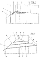
Figur 1 ist die Ablage 1 in Form eines Dreiecks dargestellt. An ihren Außenseiten 3 und 4 ist die Ablage 1 in den Querfugen 13, 14 zwischen den Wandfliesen 10 und 11 bzw. 18 und 19 fixiert. Dabei veranschaulichtFigur 1 bereits eindrucksvoll, wie filigran die erfindungsgemäße Ablage 1 baut und wie leicht sie über die hier nicht erkennbaren Flansche in den Fugen 13, 14 verankert werden kann, so dass sich eine maximale Grundfläche 2 ausbildet, die dann zur Aufnahme von Pflegemitteln und -artikeln optimal genutzt werden kann. Erkennbar ist inFigur 1 an der dritten Außenseite 5 der Ablage 1 eine nach unten ausgebildete Abwinklung 16. - Eine Variante zeigt
Figur 2 in Form eines umlaufenden Rahmens 28, jeweils an den Seiten 3, 4 und 5, bei dem es sich entweder um in Bezug auf die Grundfläche nach oben abgekantete Abwinklungen handelt oder in den Rahmen 28 ist eine als separates Bauteil ausgebildete Platte 29 einzusetzen, die dann die Grundfläche 2 bildet. - Ein solcher Rahmen 29 ist dann in
Figur 3 veranschaulicht, ohne dass eine Grundplatte eingesetzt ist. -
Figur 4 zeigt eine Ablage 1, die aus drei Abschnitten 25, 26 und 27 besteht bzw. zusammengesetzt ist. D. h. ein erster kleiner, dreieckförmiger Abschnitt 25 befindet sich unmittelbar im Eckbereich 30. Dieser Abschnitt 25 ist an den beiden Außenseiten 3 und 4 des Abschnitts 25 in den Fugen 13, 14 fixiert. An diesen ersten Abschnitt 25 schließt sich ein weiterer Abschnitt 26 mit einer trapezförmigen Grundform an, dessen Außenseiten 6, 8 in den Fugen 13, 14 fixiert sind. Schließlich ist ein dritter Abschnitt 27 ausgebildet, ebenfalls in Trapezform und verankert an den Außen- bzw. Stirnseiten 7 und 9. - In Draufsicht zeigt nun
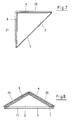
Figur 5 eine Ablage 1 in Form eines Dreiecks mit der Grundfläche 2 und den Außenseiten 3 und 4, die in der Wandung zu verankern sind, während die dritte Seite 5 den Abschluss der Grundfläche 2 bildet. Angedeutet ist im Bereich des Stoßes 15 zwischen den beiden in der Wandung zu verankernden Seiten 3, 4 eine kleine Ausnehmung 16, die z.B. durch Abfasen entstanden ist und die eine Beeinträchtigung der Funktion des dort verlaufenden Dichtbandes verhindert. - In
Figur 6 ist nochmals gut die Abwinklung 17 zu erkennen, die z. B. als weitere Sicherung gegen das Herunterfallen von auf der Grundfläche 2 positionierten Gegenständen dient, insbesondere wenn diese Abwinklung 17 nach oben reicht. - Dargestellt ist in
Figur 7 dann insbesondere der jeweilige Auflagerflansch 20, 21 an den Außenseiten 3, 4, der in etwa parallel zur Grundfläche 2 der Ablage 1 verläuft und somit zu einer denkbar einfachen Installierung der Ablage 1 in einer hier nicht dargestellten Fuge durch entsprechende Verankerung dient. - Hierzu auch noch
Figur 8 mit den abstehenden Flanschen 20, 21 an den Außenseiten 3, 4 und der Abwinklung 17 an der Außenseite 5. - In Form eines nicht gleichschenkligen Dreiecks zeigt
Figur 9 eine erfindungsgemäße Ablage 1 mit den in der Wandung zu verankernden Außenseiten 3, 4 bzw. Flanschen 20, 21. - Eine Öffnung 24 in der Mitte der Grundfläche 2 der Ablage 1 ist zentraler Gegenstand von
Figur 10 . Ergänzend etwa zur geneigten Anordnung solch einer Ablage 1 ist eine Öffnung 24 realisiert, die ein Ablaufen Wasser und ein damit einhergehendes Verschmutzen oder eine sonstige Beeinträchtigung ausschließt. Außerdem kann die Öffnung 24 dazu dienen, andere Utensilien wie Becher etc. aufzunehmen. - Schließlich zeigt
Figur 11 in Draufsicht eine Ablage 1 mit der Grundfläche 2 in Trapezform wobei die an den Außenseiten 6, 8 vorgesehenen Flansche 22, 23 zur Verankerung in den Fugen dienen.
Claims (13)
- Ablage (1) mit einer Grundfläche (2) zur Aufnahme von Gegenständen, wobei die Ablage (1) an mindestens zwei ihrer Außenseiten (3 - 9) in einer zwischen Wandfliesen (10, 11) verlaufenden Querfuge (13, 14) oder einer Nut fixierbar ist.
- Ablage nach Anspruch 1,
dadurch gekennzeichnet,
dass die Ablage (1) ausschließlich in einer zwischen Wandfliesen (10, 11) verlaufenden Querfuge (13, 14) oder einer Nut verankert ist. - Ablage nach Anspruch 1,
dadurch gekennzeichnet,
dass die Ablage (1) an zwei benachbarten Außenseiten (3, 4) in jeweils einer Querfuge (13, 14) oder einer Nut fixierbar ist. - Ablage nach Anspruch 1,
dadurch gekennzeichnet,
dass die Ablage (1) an mindestens zwei einander gegenüber liegenden Außenseiten (6, 8) in jeweils einer Querfuge oder einer Nut fixierbar ist. - Ablage nach Anspruch 1,
dadurch gekennzeichnet,
dass die Ablage (1) an mindestens einer Außenseite (3, 4, 5) eine Abwinklung (17) aufweist. - Ablage nach Anspruch 1,
dadurch gekennzeichnet,
dass die Ablage (1) mindestens einen zur Verankerung der Ablage (1) in einer Querfuge oder einer Nut dienenden Auflagerflansch (20 - 23) aufweist. - Ablage nach Anspruch 6,
dadurch gekennzeichnet,
dass der Auflagerflansch (20 - 23) sich im Wesentlichen in oder parallel zu der Ebene der Ablage (1) erstreckt. - Ablage nach Anspruch 1,
dadurch gekennzeichnet,
dass die Ablage (1) im Bereich des Stoßes (15) der benachbarten Außenseiten (3, 4) eine Abrundung (16) aufweist. - Ablage nach Anspruch 1,
dadurch gekennzeichnet,
dass die Grundfläche (2) mindestens eine Öffnung (24) aufweist. - Ablage nach Anspruch 1,
dadurch gekennzeichnet,
dass die Ablage (1) mehrere parallel zueinander angeordnete Abschnitte (25, 26, 27) aufweist. - Ablage nach Anspruch 10,
dadurch gekennzeichnet,
dass die Ablage (1) einen ersten Abschnitt (25) aufweist, bei dem zwei rechtwinklig aneinander stoßende Außenseiten (3, 4) in einer Querfuge (13, 14) oder einer Nut fixierbar sind. - Ablage nach Anspruch 10 oder 11,
dadurch gekennzeichnet,
dass die Ablage (1) mindestens einen weiteren Abschnitt (26) aufweist, bei dem zwei gegenüber liegende Außenseiten (6, 8) in einer Fuge (13, 14) oder einer Nut fixierbar sind. - Ablage nach Anspruch 1,
dadurch gekennzeichnet,
dass die Ablage (1) als Rahmen (28) zur Aufnahme einer als separates Bauteil ausgebildeten, die Grundfläche (2) aufweisenden Platte (29) ausgebildet ist.
Applications Claiming Priority (1)
| Application Number | Priority Date | Filing Date | Title |
|---|---|---|---|
| DE102014110771.3A DE102014110771A1 (de) | 2014-07-30 | 2014-07-30 | Kompakt bauende Duschablage |
Publications (2)
| Publication Number | Publication Date |
|---|---|
| EP2979597A1 true EP2979597A1 (de) | 2016-02-03 |
| EP2979597B1 EP2979597B1 (de) | 2022-04-27 |
Family
ID=53765121
Family Applications (1)
| Application Number | Title | Priority Date | Filing Date |
|---|---|---|---|
| EP15178837.9A Revoked EP2979597B1 (de) | 2014-07-30 | 2015-07-29 | Kompakt bauende duschablage |
Country Status (2)
| Country | Link |
|---|---|
| EP (1) | EP2979597B1 (de) |
| DE (2) | DE102014110771A1 (de) |
Cited By (5)
| Publication number | Priority date | Publication date | Assignee | Title |
|---|---|---|---|---|
| DE202019101555U1 (de) | 2019-03-19 | 2019-05-09 | Reger & Heidt GbR (vertretungsberechtigte Gesellschafter: Albert Reger, 91413 Neustadt an der Aisch, Eduard Heidt, 91413 Neustadt an der Aisch) | Duschablage |
| DE202018102357U1 (de) * | 2018-04-26 | 2019-07-29 | Schlüter-Systems Kg | Duschablage |
| EP3516990A1 (de) * | 2018-01-30 | 2019-07-31 | Dario Mangili | Ablagevorrichtung sowie system umfassend eine ablagevorrichtung |
| EP3708050A1 (de) | 2019-03-12 | 2020-09-16 | Manuel Groß-Bölting | Profilschiene für duschablagen |
| USD1003631S1 (en) | 2020-01-28 | 2023-11-07 | Schluter Systems L.P. | Shelf |
Families Citing this family (3)
| Publication number | Priority date | Publication date | Assignee | Title |
|---|---|---|---|---|
| DE102016007282A1 (de) * | 2016-06-15 | 2017-12-21 | Karl-Heinz Fiedler | Dekor- und/oder Funktionsteil für den Einbau in einen Eckbereich oder eine Nische, beispielsweise eines zumindest teilweise gefliesten Raumes |
| DE202019104493U1 (de) | 2019-08-15 | 2020-01-21 | M.A.C.'s Holding Gmbh | Montagevorrichtung für Bad- oder Küchenutensilien |
| DE102022100150A1 (de) | 2022-01-04 | 2023-07-06 | F & S Metallverarbeitung GmbH & Co. KG | Wandhalterung sowie Montageverfahren für diese Wandhalterung |
Citations (10)
| Publication number | Priority date | Publication date | Assignee | Title |
|---|---|---|---|---|
| US1599654A (en) | 1925-06-16 | 1926-09-14 | Cranston Arthur | Shelf and similar structure |
| US2522442A (en) | 1947-12-22 | 1950-09-12 | Marian A Garris | Demountable corner shelf |
| JPS644233U (de) * | 1987-06-30 | 1989-01-11 | ||
| US6301725B1 (en) | 1999-01-06 | 2001-10-16 | Brian Harvey | Corner shower seat |
| US20050235410A1 (en) * | 2004-04-22 | 2005-10-27 | Syed Rizvi | Shower tray |
| US20090090683A1 (en) | 2007-10-05 | 2009-04-09 | Alireza Haghayegh | Corner shelf system |
| US20090183306A1 (en) * | 2008-01-22 | 2009-07-23 | Kik Jr Paul | Shower bench |
| US20110167746A1 (en) | 2010-01-14 | 2011-07-14 | Scalise David H | Tiled structures and brackets therefor |
| WO2014023621A1 (de) * | 2012-08-08 | 2014-02-13 | KNOLL SEN., Alexander | Anordnung zur befestigung einer ablagevorrichtung |
| DE202014000851U1 (de) | 2014-01-30 | 2014-02-25 | Manuel Groß-Bölting | Duschablage |
Family Cites Families (3)
| Publication number | Priority date | Publication date | Assignee | Title |
|---|---|---|---|---|
| US2261078A (en) | 1939-10-27 | 1941-10-28 | Franklin P Shockey | Shelf and mounting therefor |
| US6059128A (en) | 1999-09-27 | 2000-05-09 | Wang; Fu-To | Corner shelf device |
| ITMI20120279U1 (it) | 2012-07-24 | 2014-01-25 | Nicola Archilli | Mensola angolare a montaggio facilitato |
-
2014
- 2014-07-30 DE DE102014110771.3A patent/DE102014110771A1/de not_active Withdrawn
-
2015
- 2015-07-29 DE DE202015009398.1U patent/DE202015009398U1/de not_active Expired - Lifetime
- 2015-07-29 EP EP15178837.9A patent/EP2979597B1/de not_active Revoked
Patent Citations (10)
| Publication number | Priority date | Publication date | Assignee | Title |
|---|---|---|---|---|
| US1599654A (en) | 1925-06-16 | 1926-09-14 | Cranston Arthur | Shelf and similar structure |
| US2522442A (en) | 1947-12-22 | 1950-09-12 | Marian A Garris | Demountable corner shelf |
| JPS644233U (de) * | 1987-06-30 | 1989-01-11 | ||
| US6301725B1 (en) | 1999-01-06 | 2001-10-16 | Brian Harvey | Corner shower seat |
| US20050235410A1 (en) * | 2004-04-22 | 2005-10-27 | Syed Rizvi | Shower tray |
| US20090090683A1 (en) | 2007-10-05 | 2009-04-09 | Alireza Haghayegh | Corner shelf system |
| US20090183306A1 (en) * | 2008-01-22 | 2009-07-23 | Kik Jr Paul | Shower bench |
| US20110167746A1 (en) | 2010-01-14 | 2011-07-14 | Scalise David H | Tiled structures and brackets therefor |
| WO2014023621A1 (de) * | 2012-08-08 | 2014-02-13 | KNOLL SEN., Alexander | Anordnung zur befestigung einer ablagevorrichtung |
| DE202014000851U1 (de) | 2014-01-30 | 2014-02-25 | Manuel Groß-Bölting | Duschablage |
Cited By (8)
| Publication number | Priority date | Publication date | Assignee | Title |
|---|---|---|---|---|
| EP3516990A1 (de) * | 2018-01-30 | 2019-07-31 | Dario Mangili | Ablagevorrichtung sowie system umfassend eine ablagevorrichtung |
| DE202018102357U1 (de) * | 2018-04-26 | 2019-07-29 | Schlüter-Systems Kg | Duschablage |
| EP3708050A1 (de) | 2019-03-12 | 2020-09-16 | Manuel Groß-Bölting | Profilschiene für duschablagen |
| DE102019106279A1 (de) * | 2019-03-12 | 2020-09-17 | Manuel Groß-Bölting | Profilschiene für Duschablagen |
| EP3708050B1 (de) * | 2019-03-12 | 2023-04-19 | Manuel Groß-Bölting | Profilschiene für duschablagen |
| DE202019101555U1 (de) | 2019-03-19 | 2019-05-09 | Reger & Heidt GbR (vertretungsberechtigte Gesellschafter: Albert Reger, 91413 Neustadt an der Aisch, Eduard Heidt, 91413 Neustadt an der Aisch) | Duschablage |
| DE102020105490B4 (de) | 2019-03-19 | 2022-03-10 | Reger & Heidt GbR (vertretungsberechtigte Gesellschafter: Albert Reger, 91413 Neustadt an der Aisch, Eduard Heidt, 91413 Neustadt an der Aisch) | Duschablage |
| USD1003631S1 (en) | 2020-01-28 | 2023-11-07 | Schluter Systems L.P. | Shelf |
Also Published As
| Publication number | Publication date |
|---|---|
| EP2979597B1 (de) | 2022-04-27 |
| DE102014110771A1 (de) | 2016-02-04 |
| DE202015009398U1 (de) | 2017-06-12 |
Similar Documents
| Publication | Publication Date | Title |
|---|---|---|
| EP2979597B1 (de) | Kompakt bauende duschablage | |
| EP0477721A2 (de) | Abgehängte Kassettendecke | |
| DE202011051140U1 (de) | Abdeckkasten für ein Duschablaufsystem | |
| DE3326790C2 (de) | ||
| DE202009009407U1 (de) | Fußbodenprofilanordnung | |
| DE102019135414A1 (de) | Ablaufarmatur für eine sanitäre Wanne oder Duschtasse | |
| DE4311468C1 (de) | Haltestange zum Halten und/oder Aussteifen von Trennwänden für Duschkabinen | |
| EP2756137A1 (de) | Ablaufrinne für eine bodengleiche dusche | |
| DE102016115677B4 (de) | Wandablage für Bad- oder Duschutensilien | |
| EP2957685B1 (de) | Verbindung zwischen wandelementen | |
| WO2010141970A1 (de) | Wandverkleidung | |
| DE102020105490A1 (de) | Duschablage | |
| DE202015105784U1 (de) | Regal mit einfacher Verbindungstechnik | |
| DE102009044421A1 (de) | Verstellbare Justierschiene | |
| DE19948468A1 (de) | Kasten für Rolläden oder dergleichen | |
| EP2476816A2 (de) | Treppenkantenprofil | |
| AT11325U1 (de) | Vorbaurollladen | |
| DE102006016022B4 (de) | Vorrichtung zur drehbaren Halterung von zwei Flächenelementen und deren Verwendung | |
| DE3818403A1 (de) | Duschkabine | |
| DE10313391B4 (de) | Duschwanne sowie Herstellungsverfahren und Duschkabine | |
| DE202012101408U1 (de) | Plattenförmiges Bauelement | |
| EP3708050B1 (de) | Profilschiene für duschablagen | |
| EP0783862B1 (de) | Wannenträger für Bade- oder Duschwannen | |
| DE3827574C2 (de) | ||
| DE202010007429U1 (de) | Schubladenwandelement und Schublade |
Legal Events
| Date | Code | Title | Description |
|---|---|---|---|
| PUAI | Public reference made under article 153(3) epc to a published international application that has entered the european phase |
Free format text: ORIGINAL CODE: 0009012 |
|
| AK | Designated contracting states |
Kind code of ref document: A1 Designated state(s): AL AT BE BG CH CY CZ DE DK EE ES FI FR GB GR HR HU IE IS IT LI LT LU LV MC MK MT NL NO PL PT RO RS SE SI SK SM TR |
|
| AX | Request for extension of the european patent |
Extension state: BA ME |
|
| 17P | Request for examination filed |
Effective date: 20160803 |
|
| RBV | Designated contracting states (corrected) |
Designated state(s): AL AT BE BG CH CY CZ DE DK EE ES FI FR GB GR HR HU IE IS IT LI LT LU LV MC MK MT NL NO PL PT RO RS SE SI SK SM TR |
|
| STAA | Information on the status of an ep patent application or granted ep patent |
Free format text: STATUS: EXAMINATION IS IN PROGRESS |
|
| 17Q | First examination report despatched |
Effective date: 20170313 |
|
| TPAC | Observations filed by third parties |
Free format text: ORIGINAL CODE: EPIDOSNTIPA |
|
| REG | Reference to a national code |
Ref country code: DE Ref legal event code: R079 Ref document number: 502015015798 Country of ref document: DE Free format text: PREVIOUS MAIN CLASS: A47K0003280000 Ipc: A47B0096020000 |
|
| GRAP | Despatch of communication of intention to grant a patent |
Free format text: ORIGINAL CODE: EPIDOSNIGR1 |
|
| STAA | Information on the status of an ep patent application or granted ep patent |
Free format text: STATUS: GRANT OF PATENT IS INTENDED |
|
| RIC1 | Information provided on ipc code assigned before grant |
Ipc: A47K 3/28 20060101ALI20211213BHEP Ipc: A47B 96/02 20060101AFI20211213BHEP |
|
| INTG | Intention to grant announced |
Effective date: 20220107 |
|
| GRAS | Grant fee paid |
Free format text: ORIGINAL CODE: EPIDOSNIGR3 |
|
| GRAA | (expected) grant |
Free format text: ORIGINAL CODE: 0009210 |
|
| STAA | Information on the status of an ep patent application or granted ep patent |
Free format text: STATUS: THE PATENT HAS BEEN GRANTED |
|
| AK | Designated contracting states |
Kind code of ref document: B1 Designated state(s): AL AT BE BG CH CY CZ DE DK EE ES FI FR GB GR HR HU IE IS IT LI LT LU LV MC MK MT NL NO PL PT RO RS SE SI SK SM TR |
|
| REG | Reference to a national code |
Ref country code: GB Ref legal event code: FG4D Free format text: NOT ENGLISH |
|
| REG | Reference to a national code |
Ref country code: CH Ref legal event code: EP |
|
| REG | Reference to a national code |
Ref country code: DE Ref legal event code: R096 Ref document number: 502015015798 Country of ref document: DE |
|
| REG | Reference to a national code |
Ref country code: AT Ref legal event code: REF Ref document number: 1486259 Country of ref document: AT Kind code of ref document: T Effective date: 20220515 |
|
| REG | Reference to a national code |
Ref country code: IE Ref legal event code: FG4D Free format text: LANGUAGE OF EP DOCUMENT: GERMAN |
|
| REG | Reference to a national code |
Ref country code: NL Ref legal event code: FP |
|
| REG | Reference to a national code |
Ref country code: LT Ref legal event code: MG9D |
|
| PG25 | Lapsed in a contracting state [announced via postgrant information from national office to epo] |
Ref country code: SE Free format text: LAPSE BECAUSE OF FAILURE TO SUBMIT A TRANSLATION OF THE DESCRIPTION OR TO PAY THE FEE WITHIN THE PRESCRIBED TIME-LIMIT Effective date: 20220427 Ref country code: PT Free format text: LAPSE BECAUSE OF FAILURE TO SUBMIT A TRANSLATION OF THE DESCRIPTION OR TO PAY THE FEE WITHIN THE PRESCRIBED TIME-LIMIT Effective date: 20220829 Ref country code: NO Free format text: LAPSE BECAUSE OF FAILURE TO SUBMIT A TRANSLATION OF THE DESCRIPTION OR TO PAY THE FEE WITHIN THE PRESCRIBED TIME-LIMIT Effective date: 20220727 Ref country code: LT Free format text: LAPSE BECAUSE OF FAILURE TO SUBMIT A TRANSLATION OF THE DESCRIPTION OR TO PAY THE FEE WITHIN THE PRESCRIBED TIME-LIMIT Effective date: 20220427 Ref country code: HR Free format text: LAPSE BECAUSE OF FAILURE TO SUBMIT A TRANSLATION OF THE DESCRIPTION OR TO PAY THE FEE WITHIN THE PRESCRIBED TIME-LIMIT Effective date: 20220427 Ref country code: GR Free format text: LAPSE BECAUSE OF FAILURE TO SUBMIT A TRANSLATION OF THE DESCRIPTION OR TO PAY THE FEE WITHIN THE PRESCRIBED TIME-LIMIT Effective date: 20220728 Ref country code: FI Free format text: LAPSE BECAUSE OF FAILURE TO SUBMIT A TRANSLATION OF THE DESCRIPTION OR TO PAY THE FEE WITHIN THE PRESCRIBED TIME-LIMIT Effective date: 20220427 Ref country code: ES Free format text: LAPSE BECAUSE OF FAILURE TO SUBMIT A TRANSLATION OF THE DESCRIPTION OR TO PAY THE FEE WITHIN THE PRESCRIBED TIME-LIMIT Effective date: 20220427 Ref country code: BG Free format text: LAPSE BECAUSE OF FAILURE TO SUBMIT A TRANSLATION OF THE DESCRIPTION OR TO PAY THE FEE WITHIN THE PRESCRIBED TIME-LIMIT Effective date: 20220727 |
|
| PGFP | Annual fee paid to national office [announced via postgrant information from national office to epo] |
Ref country code: LU Payment date: 20220726 Year of fee payment: 8 |
|
| PG25 | Lapsed in a contracting state [announced via postgrant information from national office to epo] |
Ref country code: RS Free format text: LAPSE BECAUSE OF FAILURE TO SUBMIT A TRANSLATION OF THE DESCRIPTION OR TO PAY THE FEE WITHIN THE PRESCRIBED TIME-LIMIT Effective date: 20220427 Ref country code: PL Free format text: LAPSE BECAUSE OF FAILURE TO SUBMIT A TRANSLATION OF THE DESCRIPTION OR TO PAY THE FEE WITHIN THE PRESCRIBED TIME-LIMIT Effective date: 20220427 Ref country code: LV Free format text: LAPSE BECAUSE OF FAILURE TO SUBMIT A TRANSLATION OF THE DESCRIPTION OR TO PAY THE FEE WITHIN THE PRESCRIBED TIME-LIMIT Effective date: 20220427 Ref country code: IS Free format text: LAPSE BECAUSE OF FAILURE TO SUBMIT A TRANSLATION OF THE DESCRIPTION OR TO PAY THE FEE WITHIN THE PRESCRIBED TIME-LIMIT Effective date: 20220827 |
|
| PGFP | Annual fee paid to national office [announced via postgrant information from national office to epo] |
Ref country code: BE Payment date: 20220726 Year of fee payment: 8 |
|
| PGFP | Annual fee paid to national office [announced via postgrant information from national office to epo] |
Ref country code: CH Payment date: 20220726 Year of fee payment: 8 |
|
| REG | Reference to a national code |
Ref country code: DE Ref legal event code: R026 Ref document number: 502015015798 Country of ref document: DE |
|
| PG25 | Lapsed in a contracting state [announced via postgrant information from national office to epo] |
Ref country code: SM Free format text: LAPSE BECAUSE OF FAILURE TO SUBMIT A TRANSLATION OF THE DESCRIPTION OR TO PAY THE FEE WITHIN THE PRESCRIBED TIME-LIMIT Effective date: 20220427 Ref country code: SK Free format text: LAPSE BECAUSE OF FAILURE TO SUBMIT A TRANSLATION OF THE DESCRIPTION OR TO PAY THE FEE WITHIN THE PRESCRIBED TIME-LIMIT Effective date: 20220427 Ref country code: RO Free format text: LAPSE BECAUSE OF FAILURE TO SUBMIT A TRANSLATION OF THE DESCRIPTION OR TO PAY THE FEE WITHIN THE PRESCRIBED TIME-LIMIT Effective date: 20220427 Ref country code: EE Free format text: LAPSE BECAUSE OF FAILURE TO SUBMIT A TRANSLATION OF THE DESCRIPTION OR TO PAY THE FEE WITHIN THE PRESCRIBED TIME-LIMIT Effective date: 20220427 Ref country code: DK Free format text: LAPSE BECAUSE OF FAILURE TO SUBMIT A TRANSLATION OF THE DESCRIPTION OR TO PAY THE FEE WITHIN THE PRESCRIBED TIME-LIMIT Effective date: 20220427 Ref country code: CZ Free format text: LAPSE BECAUSE OF FAILURE TO SUBMIT A TRANSLATION OF THE DESCRIPTION OR TO PAY THE FEE WITHIN THE PRESCRIBED TIME-LIMIT Effective date: 20220427 |
|
| PLBI | Opposition filed |
Free format text: ORIGINAL CODE: 0009260 |
|
| PLAX | Notice of opposition and request to file observation + time limit sent |
Free format text: ORIGINAL CODE: EPIDOSNOBS2 |
|
| PG25 | Lapsed in a contracting state [announced via postgrant information from national office to epo] |
Ref country code: MC Free format text: LAPSE BECAUSE OF FAILURE TO SUBMIT A TRANSLATION OF THE DESCRIPTION OR TO PAY THE FEE WITHIN THE PRESCRIBED TIME-LIMIT Effective date: 20220427 |
|
| 26 | Opposition filed |
Opponent name: HK-EDELSTAHL-DEKO Effective date: 20230126 |
|
| PG25 | Lapsed in a contracting state [announced via postgrant information from national office to epo] |
Ref country code: AL Free format text: LAPSE BECAUSE OF FAILURE TO SUBMIT A TRANSLATION OF THE DESCRIPTION OR TO PAY THE FEE WITHIN THE PRESCRIBED TIME-LIMIT Effective date: 20220427 |
|
| PG25 | Lapsed in a contracting state [announced via postgrant information from national office to epo] |
Ref country code: FR Free format text: LAPSE BECAUSE OF NON-PAYMENT OF DUE FEES Effective date: 20220731 |
|
| PG25 | Lapsed in a contracting state [announced via postgrant information from national office to epo] |
Ref country code: SI Free format text: LAPSE BECAUSE OF FAILURE TO SUBMIT A TRANSLATION OF THE DESCRIPTION OR TO PAY THE FEE WITHIN THE PRESCRIBED TIME-LIMIT Effective date: 20220427 |
|
| PLBB | Reply of patent proprietor to notice(s) of opposition received |
Free format text: ORIGINAL CODE: EPIDOSNOBS3 |
|
| PG25 | Lapsed in a contracting state [announced via postgrant information from national office to epo] |
Ref country code: IE Free format text: LAPSE BECAUSE OF NON-PAYMENT OF DUE FEES Effective date: 20220729 |
|
| PGFP | Annual fee paid to national office [announced via postgrant information from national office to epo] |
Ref country code: NL Payment date: 20230726 Year of fee payment: 9 |
|
| P01 | Opt-out of the competence of the unified patent court (upc) registered |
Effective date: 20230808 |
|
| PGFP | Annual fee paid to national office [announced via postgrant information from national office to epo] |
Ref country code: GB Payment date: 20230725 Year of fee payment: 9 Ref country code: AT Payment date: 20230718 Year of fee payment: 9 |
|
| PGFP | Annual fee paid to national office [announced via postgrant information from national office to epo] |
Ref country code: DE Payment date: 20230727 Year of fee payment: 9 |
|
| PG25 | Lapsed in a contracting state [announced via postgrant information from national office to epo] |
Ref country code: IT Free format text: LAPSE BECAUSE OF FAILURE TO SUBMIT A TRANSLATION OF THE DESCRIPTION OR TO PAY THE FEE WITHIN THE PRESCRIBED TIME-LIMIT Effective date: 20220427 |
|
| REG | Reference to a national code |
Ref country code: CH Ref legal event code: PL |
|
| REG | Reference to a national code |
Ref country code: BE Ref legal event code: MM Effective date: 20230731 |
|
| PG25 | Lapsed in a contracting state [announced via postgrant information from national office to epo] |
Ref country code: LU Free format text: LAPSE BECAUSE OF NON-PAYMENT OF DUE FEES Effective date: 20230729 |
|
| PG25 | Lapsed in a contracting state [announced via postgrant information from national office to epo] |
Ref country code: LU Free format text: LAPSE BECAUSE OF NON-PAYMENT OF DUE FEES Effective date: 20230729 Ref country code: HU Free format text: LAPSE BECAUSE OF FAILURE TO SUBMIT A TRANSLATION OF THE DESCRIPTION OR TO PAY THE FEE WITHIN THE PRESCRIBED TIME-LIMIT; INVALID AB INITIO Effective date: 20150729 |
|
| PG25 | Lapsed in a contracting state [announced via postgrant information from national office to epo] |
Ref country code: MK Free format text: LAPSE BECAUSE OF FAILURE TO SUBMIT A TRANSLATION OF THE DESCRIPTION OR TO PAY THE FEE WITHIN THE PRESCRIBED TIME-LIMIT Effective date: 20220427 Ref country code: CY Free format text: LAPSE BECAUSE OF FAILURE TO SUBMIT A TRANSLATION OF THE DESCRIPTION OR TO PAY THE FEE WITHIN THE PRESCRIBED TIME-LIMIT Effective date: 20220427 Ref country code: CH Free format text: LAPSE BECAUSE OF NON-PAYMENT OF DUE FEES Effective date: 20230731 |
|
| PG25 | Lapsed in a contracting state [announced via postgrant information from national office to epo] |
Ref country code: BE Free format text: LAPSE BECAUSE OF NON-PAYMENT OF DUE FEES Effective date: 20230731 |
|
| RDAF | Communication despatched that patent is revoked |
Free format text: ORIGINAL CODE: EPIDOSNREV1 |
|
| REG | Reference to a national code |
Ref country code: DE Ref legal event code: R103 Ref document number: 502015015798 Country of ref document: DE Ref country code: DE Ref legal event code: R064 Ref document number: 502015015798 Country of ref document: DE |
|
| RDAG | Patent revoked |
Free format text: ORIGINAL CODE: 0009271 |
|
| STAA | Information on the status of an ep patent application or granted ep patent |
Free format text: STATUS: PATENT REVOKED |
|
| PG25 | Lapsed in a contracting state [announced via postgrant information from national office to epo] |
Ref country code: MT Free format text: LAPSE BECAUSE OF FAILURE TO SUBMIT A TRANSLATION OF THE DESCRIPTION OR TO PAY THE FEE WITHIN THE PRESCRIBED TIME-LIMIT Effective date: 20220427 |
|
| REG | Reference to a national code |
Ref country code: CH Ref legal event code: PL |
|
| 27W | Patent revoked |
Effective date: 20240607 |
|
| GBPR | Gb: patent revoked under art. 102 of the ep convention designating the uk as contracting state |
Effective date: 20240607 |
|
| PG25 | Lapsed in a contracting state [announced via postgrant information from national office to epo] |
Ref country code: BG Free format text: LAPSE BECAUSE OF FAILURE TO SUBMIT A TRANSLATION OF THE DESCRIPTION OR TO PAY THE FEE WITHIN THE PRESCRIBED TIME-LIMIT Effective date: 20220427 |
|
| PG25 | Lapsed in a contracting state [announced via postgrant information from national office to epo] |
Ref country code: BG Free format text: LAPSE BECAUSE OF FAILURE TO SUBMIT A TRANSLATION OF THE DESCRIPTION OR TO PAY THE FEE WITHIN THE PRESCRIBED TIME-LIMIT Effective date: 20220427 |
|
| REG | Reference to a national code |
Ref country code: AT Ref legal event code: MA03 Ref document number: 1486259 Country of ref document: AT Kind code of ref document: T Effective date: 20240607 |
|
| PG25 | Lapsed in a contracting state [announced via postgrant information from national office to epo] |
Ref country code: TR Free format text: LAPSE BECAUSE OF FAILURE TO SUBMIT A TRANSLATION OF THE DESCRIPTION OR TO PAY THE FEE WITHIN THE PRESCRIBED TIME-LIMIT Effective date: 20220427 |